EP4390492A1 - Prism assembly, prism motor, and electronic device - Google Patents
Prism assembly, prism motor, and electronic device Download PDFInfo
- Publication number
- EP4390492A1 EP4390492A1 EP23762668.4A EP23762668A EP4390492A1 EP 4390492 A1 EP4390492 A1 EP 4390492A1 EP 23762668 A EP23762668 A EP 23762668A EP 4390492 A1 EP4390492 A1 EP 4390492A1
- Authority
- EP
- European Patent Office
- Prior art keywords
- prism
- magnet
- assembly
- motor
- support
- Prior art date
- Legal status (The legal status is an assumption and is not a legal conclusion. Google has not performed a legal analysis and makes no representation as to the accuracy of the status listed.)
- Pending
Links
Images



Classifications
-
- G—PHYSICS
- G02—OPTICS
- G02B—OPTICAL ELEMENTS, SYSTEMS OR APPARATUS
- G02B7/00—Mountings, adjusting means, or light-tight connections, for optical elements
- G02B7/18—Mountings, adjusting means, or light-tight connections, for optical elements for prisms; for mirrors
-
- G—PHYSICS
- G02—OPTICS
- G02B—OPTICAL ELEMENTS, SYSTEMS OR APPARATUS
- G02B7/00—Mountings, adjusting means, or light-tight connections, for optical elements
- G02B7/18—Mountings, adjusting means, or light-tight connections, for optical elements for prisms; for mirrors
- G02B7/1805—Mountings, adjusting means, or light-tight connections, for optical elements for prisms; for mirrors for prisms
-
- G—PHYSICS
- G02—OPTICS
- G02B—OPTICAL ELEMENTS, SYSTEMS OR APPARATUS
- G02B26/00—Optical devices or arrangements for the control of light using movable or deformable optical elements
- G02B26/08—Optical devices or arrangements for the control of light using movable or deformable optical elements for controlling the direction of light
- G02B26/0875—Optical devices or arrangements for the control of light using movable or deformable optical elements for controlling the direction of light by means of one or more refracting elements
- G02B26/0883—Optical devices or arrangements for the control of light using movable or deformable optical elements for controlling the direction of light by means of one or more refracting elements the refracting element being a prism
-
- G—PHYSICS
- G03—PHOTOGRAPHY; CINEMATOGRAPHY; ANALOGOUS TECHNIQUES USING WAVES OTHER THAN OPTICAL WAVES; ELECTROGRAPHY; HOLOGRAPHY
- G03B—APPARATUS OR ARRANGEMENTS FOR TAKING PHOTOGRAPHS OR FOR PROJECTING OR VIEWING THEM; APPARATUS OR ARRANGEMENTS EMPLOYING ANALOGOUS TECHNIQUES USING WAVES OTHER THAN OPTICAL WAVES; ACCESSORIES THEREFOR
- G03B17/00—Details of cameras or camera bodies; Accessories therefor
- G03B17/02—Bodies
- G03B17/17—Bodies with reflectors arranged in beam forming the photographic image, e.g. for reducing dimensions of camera
-
- G—PHYSICS
- G03—PHOTOGRAPHY; CINEMATOGRAPHY; ANALOGOUS TECHNIQUES USING WAVES OTHER THAN OPTICAL WAVES; ELECTROGRAPHY; HOLOGRAPHY
- G03B—APPARATUS OR ARRANGEMENTS FOR TAKING PHOTOGRAPHS OR FOR PROJECTING OR VIEWING THEM; APPARATUS OR ARRANGEMENTS EMPLOYING ANALOGOUS TECHNIQUES USING WAVES OTHER THAN OPTICAL WAVES; ACCESSORIES THEREFOR
- G03B30/00—Camera modules comprising integrated lens units and imaging units, specially adapted for being embedded in other devices, e.g. mobile phones or vehicles
-
- H—ELECTRICITY
- H02—GENERATION; CONVERSION OR DISTRIBUTION OF ELECTRIC POWER
- H02K—DYNAMO-ELECTRIC MACHINES
- H02K1/00—Details of the magnetic circuit
- H02K1/06—Details of the magnetic circuit characterised by the shape, form or construction
- H02K1/22—Rotating parts of the magnetic circuit
- H02K1/27—Rotor cores with permanent magnets
- H02K1/2706—Inner rotors
- H02K1/272—Inner rotors the magnetisation axis of the magnets being perpendicular to the rotor axis
- H02K1/274—Inner rotors the magnetisation axis of the magnets being perpendicular to the rotor axis the rotor consisting of two or more circumferentially positioned magnets
- H02K1/2753—Inner rotors the magnetisation axis of the magnets being perpendicular to the rotor axis the rotor consisting of two or more circumferentially positioned magnets the rotor consisting of magnets or groups of magnets arranged with alternating polarity
-
- H—ELECTRICITY
- H02—GENERATION; CONVERSION OR DISTRIBUTION OF ELECTRIC POWER
- H02K—DYNAMO-ELECTRIC MACHINES
- H02K41/00—Propulsion systems in which a rigid body is moved along a path due to dynamo-electric interaction between the body and a magnetic field travelling along the path
- H02K41/02—Linear motors; Sectional motors
- H02K41/035—DC motors; Unipolar motors
- H02K41/0352—Unipolar motors
- H02K41/0354—Lorentz force motors, e.g. voice coil motors
-
- H—ELECTRICITY
- H02—GENERATION; CONVERSION OR DISTRIBUTION OF ELECTRIC POWER
- H02K—DYNAMO-ELECTRIC MACHINES
- H02K2201/00—Specific aspects not provided for in the other groups of this subclass relating to the magnetic circuits
- H02K2201/18—Machines moving with multiple degrees of freedom
Definitions
- This application relates to the field of electronic products, and in particular, to a prism assembly, a prism motor, and an electronic device.
- periscope prism motors are more widely used in imaging systems.
- the periscope prism motor is relatively complex in structure, and jitters, abnormal sounds, and prism assembly errors often occur when the current prism motor is used.
- An embodiment of this application provides a prism motor and an electronic device.
- the prism motor is relatively low in power consumption.
- a prism assembly of a prism motor includes at least a prism and a prism support.
- the prism support has a rotation center rotating relative to a base of a prism motor, the prism assembly is configured so that gravity of the prism assembly is within a theoretical design range relative to torque of the rotation center, and the theoretical design range is zero or a numerical range close to zero.
- a material density of the prism support is less than a material density of the prism.
- the prism assembly further includes a weight component, fixed on a side of the prism support away from the center of gravity of the prism and configured to balance at least partial torque generated by the gravity of the prism.
- the prism support may be made of plastic, and the prism may be made of glass. The purpose that the gravity of the prism assembly is smaller relative to torque of a rotation center line can be realized by additionally adding the weight component on the current prism support, so that improvement costs are lower.
- the center of gravity of the prism assembly coincides with the rotation center.
- the moment generated by the center of gravity of the prism assembly is zero, so that a driving force required by the prism motor is reduced to a great extent, and power consumption is low.
- the prism assembly further includes a magnet assembly fixed on the prism support and configured to be mated with a driving coil of the prism motor to drive the prism assembly to rotate around the rotation center; and the weight component is the magnet assembly.
- the magnet assembly generating the driving force serves as the weight component, so that driving requirements can be met, and the driving force of the prism motor is reduced without adding redundant components.
- the prism motor is compact in volume and low in power consumption.
- the magnet assembly includes a first magnet and a second magnet, a volume of the first magnet is greater than a volume of the second magnet, and the first magnet is located on a side of the second magnet away from a light-emitting surface of the prism.
- the volume of the first magnet increases toward the side away from the prism, and accordingly, a center-of-gravity position of the entire prism assembly approaches the rotation center, so that flexible adjustment is achieved, and a better effect is realized.
- the first magnet and the second magnet are cuboids with a thickness
- the sizes of adjacent sides of the first magnet and the second magnet are the same
- the size of the other side of the first magnet is greater than the size of the other side of the second magnet.
- the prism and the two magnets are simple in structure, and are easy to machine and mount.
- the prism is a triple prism
- the second side surface is perpendicular to a light inlet main axis of the prism
- the first side surface is parallel to an end surface of the prism.
- the two magnet assemblies are respectively defined as a first magnet assembly and a second magnet assembly;
- the base is provided with a first driving coil and a second driving coil;
- the first driving coil is mated with the first magnet assembly to generate a driving force that drives the prism assembly to rotate around the light inlet main axis;
- the second driving coil is mated with the second magnet assembly to generate a driving force that drives the prism assembly to rotate around a second axis perpendicular to a plane that is determined by the light inlet main axis and a light-emitting main axis.
- this application further provides a prism motor, including a base and the prism assembly described in any one of the above.
- this application further provides an electronic device, including the prism motor described in any one of the above.
- the prism motor and the electronic device of this application include the prism assembly, and thus have the above technical effects of the prism assembly.
- this application provides a technical solution, which can eliminate or reduce the probability of the occurrence of the above technical problems.
- FIG. 1 is an overall schematic diagram of an imaging module according to an embodiment of this application.
- FIG. 8 is an exploded view of a main structure in FIG. 1 .
- the electronic device includes an imaging module 100.
- the imaging module 100 includes a prism motor 2, a lens assembly 3, and a lens motor carrier 4.
- the lens assembly 3 (covered by a housing 1) is not shown in FIG. 1 .
- the lens assembly 3 is located in a right-side position of the prism motor 2 in FIG. 1 .
- the prism motor 2 and the lens assembly 3 may be assembled inside the housing 1, and the housing 1 mainly plays a role in protecting components located inside the housing.
- the housing 1 is provided with a light-transmitting hole 1a, and external light first enters the prism motor 2 and then enters the lens assembly 3 after being refracted by the prism motor 2.
- a main light path direction S entering the prism motor 2 and an emergent light path direction S1 after refraction of the prism motor 2 are provided in FIG. 1 , and the light enters the lens assembly in the emergent light path direction S 1.
- S is usually a thickness direction of the electronic device
- S1 is usually a length direction of the electronic device.
- FIG. 2 is a partial three-dimensional schematic diagram of a prism motor in FIG. 1 .
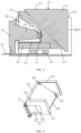
- FIG. 3 is a cross-sectional view in a direction of A-A in FIG. 2 .
- FIG. 4 is a schematic assembling diagram of a prism support, a first magnet assembly, and an elastic piece in FIG. 2 .
- the prism motor 2 further includes a base 20, a first driving coil, a prism 21, and a prism support 22.
- the prism 21 may be a triple prism.
- the triple prism is a prism with a cross section being a right-angled triangle.
- a circumferential surface of the prism includes three surfaces successively connected end to end, which are a light inlet surface 211, a light-emitting surface 212, and a reflected light surface 213.
- the light inlet surface 211 and the light-emitting surface 212 are usually vertical, and the reflected light surface 213 is an inclined surface connected between the light inlet surface 212 and the light-emitting surface 212. Only the light inlet surface 211 is shown in FIG.
- the external light enters the prism 21 via the light inlet surface, and is emitted from the prism 21 by the light-emitting surface after being reflected by the reflected light surface.
- the reflected light surface is usually mounted opposite to an inclined wall 222 of the prism support.
- the prism 21 is not limited to the triple prism described here, and may certainly be other forms of prisms, and a main function of the prism is to change a light propagation path to meet requirements for a mounting position of the lens assembly 5.
- the technical solutions and technical effects are continuously introduced by using the prism 21 being the triple prism as an example.
- the prism support 22 includes a main body 220.
- the main body 220 has two side walls 221.
- a mounting space for mounting the prism 21 is enclosed by the inclined wall 222 and the two side walls 221.
- the mounting space is an angular structure matching the triple prism.
- the reflected light surface of the prism 21 is opposite to the inclined wall 222. From FIG. 3 to FIG.
- the prism 21 may be located in the mounting space that is used for mounting the prism 21 and that is enclosed by the inclined wall 222 and the two side walls 221, and not the entire prism 21 is completely located inside the mounting space, so that the position of the prism 21 is conveniently adjusted.
- the entire prism 21 is completely located inside the mounting space, and the position of the prism 21 is conveniently adjusted by reserving enough space between the prism 21 and the prism support 22, so as to achieve an anti-jitter function of the imaging module.
- the prism 21 is fixed on the prism support 22 to form a prism assembly.
- the prism 21 may be fixed with the prism support 22 through dispensing.
- the two side walls 221 of the prism support 22 are fixed with corresponding side walls of the prism 21 through dispensing.
- fixation between the prism 21 and the prism support 22 is not limited to the description herein, but may be in other ways.
- the prism assembly is rotatably supported on the base 20, and generally, the prism support 22 is rotatably supported on the base 20. That is, the prism support 22 has a rotation center O rotating relative to the base 20 of the prism motor 2.
- the prism assembly in this application is configured so that the gravity of the prism assembly is within a theoretical design range relative to the torque of the rotation center O, and the theoretical design range is zero or a numerical range close to zero.
- the prism 21 is made of glass
- the prism support 22 is made of plastic
- materials of the prism 21 and the prism support 22 are not limited to the description herein.
- a material density of the prism support 22 is less than a material density of the prism 21, so that the center of gravity of the entire assembly formed by assembling the prism 21 and the prism support 22 is biased to the side of the prism 21, and not located in the center of the assembly.
- the rotation center O is generally located in the central position of the prism assembly, to make the center of gravity of the prism assembly as close to the rotation center as possible, the prism assembly of this application is further disposed as follows.
- the prism assembly further includes a weight component, fixed on a side of the prism support 22 away from the center of gravity of the prism 21.
- the distance between a center of gravity O' of the prism assembly formed by the prism 21, the prism support 22, and the weight component and the rotation center O is small or the center of gravity O' coincides with the rotation center O, so that the gravity of the prism assembly formed by the prism, the prism support, and the weight component is smaller relative to the torque of the rotation center.
- the gravity of the prism assembly can be smaller relative to the torque of the rotation center by additionally adding the weight component on the current prism support 22, so that improvement costs are low.
- an ideal state is that the center of gravity O' of the prism assembly coincides with the rotation center O, so that the prism assembly in a static state generates almost no torque to the rotation center O.
- the shape and material of the weight component may be rationally selected according to specific products, and even if structural parameters of the weight component are not disclosed herein, this does not create any obstacle for those skilled in the art to understand and implement the above technical solutions herein.
- the power that the prism assembly rotates relative to the rotation center O may be derived from the magnet assembly and the driving coil.
- One of the magnet assembly and the driving coil is mounted on the prism assembly, and the other one is mounted on the base.
- the magnet assembly may be mounted to the prism support 22 of the prism assembly, and may also be mounted on the base 20.
- the driving coil mated with the magnet assembly may be mounted on the base 20, and may also be mounted on the prism support 22.
- the technical solutions and technical effects are continuously introduced by using an example in which the magnet assembly is fixed on the prism support 22 of the prism assembly.
- the prism assembly further includes the magnet assembly fixed on the prism support 22 and configured to be mated with the driving coil of the prism motor to drive the prism assembly to rotate around the rotation center O.
- the driving coil When the driving coil is energized, a driving force is generated between the driving coil and the magnet assembly, and under the action of the driving force, the prism assembly may rotate relative to the rotation center.
- the direction of the driving force may be changed by changing a direction of a current introduced into the driving coil.
- the driving coil generally includes a first end and a second end that are electrically connected with an external current.
- a current introduced from the first end is defined as a forward current
- a current introduced from the second end is a reverse current
- a first driving force making the prism assembly rotate clockwise is generated by the driving coil and the magnet assembly
- a second driving force making the prism assembly rotate anticlockwise is generated by the driving coil and the magnet assembly.
- the direction of the first driving force is opposite to the direction of the second driving force, and the magnitudes of the first driving force and the second driving force may be controlled by the magnitude of the introduced current.
- the weight component is the magnet assembly.
- the driving coil assembly may include a first driving coil assembly and a second driving coil assembly.
- the first driving coil assembly is configured to drive the prism assembly to rotate around a first axis Z1
- the second driving coil assembly is configured to drive the prism assembly to rotate around a second axis.
- the first driving coil assembly is located on a first side surface 22a of the prism assembly
- the second driving coil assembly is located on a second side surface 22b of the prism assembly.
- the first axis is not parallel to the second axis.
- the prism assembly in this application can rotate around the first axis Z1 and the second axis Z2 under the driving of the first driving coil assembly and the second driving coil assembly, respectively, and the first driving coil assembly and the second driving coil assembly only occupy two side surface spaces of the prism assembly, so that a design space of a motor is saved, the size of the motor is reduced, and the cost and process difficulty of the motor are reduced.
- the first axis Z1 is parallel to the light inlet main axis S of the prism assembly, that is, the prism assembly can rotate around a direction parallel to the light inlet main axis S.
- the first axis Z1 coincides with the light inlet main axis S.
- the first axis Z1 may not coincide with the light inlet main axis S, and under the driving of the first driving coil assembly, the prism assembly can rotate a predetermined angle around the first axis Z1.
- the second axis Z2 is perpendicular to a plane determined by the light inlet main axis S and the light-emitting main axis S1 of the prism assembly, that is, the prism assembly may rotate around a point O in a cross section shown in FIG. 3 .
- the prism assembly may clockwise or anticlockwise rotate, in a pitching manner, the predetermined angle around the point O in the cross section (a vertical plane) shown in FIG. 3 .
- the first driving coil assembly includes a first driving coil 23 and a first magnet assembly 25.
- One of the first driving coil and the first magnet assembly is fixed on the base 20, and the other one is fixed on the prism assembly.
- the first driving coil 23 is fixed on the base 20 (the base is not shown, but those skilled in the art are not prevented from understanding the technical solutions herein), and the first magnet assembly 25 is fixed on the prism support 22 are shown.
- the first driving coil 23 is also fixed on the prism support 22, and the first magnet assembly 25 is fixed on the base 20.
- FIG. 2 shows a rough direction of a driving force F generated by a current introduced by the first driving coil 23.
- the first magnet assembly 25 may include a magnet, and may certainly have two or more magnets, and a specific example of including two magnets is provided below.
- the first magnet assembly 25 includes a first magnet 251 and a second magnet 252, and the volume of the first magnet 251 is greater than the volume of the second magnet 252, so that the weight of the first magnet 251 is greater than the weight of the second magnet 252. Because the first magnet 251 is located on a side of the second magnet 252 away from the light-emitting surface 22 of the prism 21, in combination with FIG. 3 for understanding, for the triple prism, the light inlet surface 211 is perpendicular to the light-emitting surface 212, the refracting surface 213 is an inclined surface, and the refracting surface 213 is mounted and positioned opposite to a protruding portion 223 of the prism support 22. From FIG.
- a protruding portion 223 (the protruding portion at a left lower corner is not shown) is disposed on each of four corners of the inclined wall 222 of the prism support 22, the refracting surface 213 of the prism 21 is partially attached to and fixed with the protruding portion 223, and there are gaps between other positions of the refracting surface 213 of the prism 21 and the inclined wall, as shown in FIG. 3 .
- Torque generated by the first magnet 251 and the second magnet 252 relative to the rotation center O and the torque of the gravity of the prism support 22 and the prism 21 relative to the rotation center O are same in magnitude, and different in direction.
- the first magnet 251 and the second magnet 252 are generally cuboids; the first magnet 251 and the second magnet 252 are the cuboids with a thickness; and the sizes of adj acent sides of the first magnet 251 and the second magnet 252 are the same, and the size of the other side of the first magnet 251 is greater than the size of the other side of the second magnet 252. That is to say, when the thicknesses of the first magnet 251 and the second magnet 252 are the same, the sizes of the sides are the same, and different sizes may be realized by configuring the sizes of the other sides.
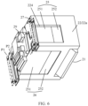
- FIG. 5 is a schematic assembling diagram of some components in FIG. 2 ; and FIG. 6 is a schematic diagram in which the driving coil in FIG. 5 is deleted.
- first sides of the first magnet 251 and the second magnet 252 in an S direction and thicknesses and sizes along S2 are the same, and the difference only lies in that the sizes of second sides in an S 1 direction are different.
- the sizes of the first sides of the first magnet 251 and the second magnet 252 in the second magnet assembly 26 in an S2 direction are the same, thicknesses in the S direction are the same, and the difference lies in that the sizes of the second sides of the first magnet and the second magnet in the S1 direction are different.
- first magnet 251 and the second magnet 252 may also be in other shapes, as long as the above technical effects can be realized.
- the magnet assembly serves as the weight component, so that the above technical problems in the prior art may be solved without adding redundant components.
- the prism is the triple prism; there are two magnet assemblies, which are respectively located on a first side surface and a second side surface of the prism support that are perpendicular to each other.
- the first driving coil is mated with the first magnet assembly to generate a driving force making the prism assembly rotate around the light inlet main axis;
- the second driving coil is mated with the second magnet assembly to generate a driving force making the prism assembly rotate around the second axis perpendicular to the plane that is determined by the light inlet main axis and the light-emitting main axis;
- the second side surface is perpendicular to the light inlet main axis of the prism; and the first side surface is parallel to an end surface of the prism.
- the first driving coil 23 may generate an acting force with the first magnet assembly 25 after being energized, so as to make the prism support 22 rotate around the first axis Z1.
- what is mated with the first driving coil 23 to generate the acting force is not limited to magnets, and may also be other magnetic field components that can generate a magnetic field.
- the second driving coil assembly includes a second driving coil 24 and a second magnet assembly 26; and one of the second driving coil and the second magnet assembly is fixed on the base, and the other one is fixed on the prism assembly.
- the second driving coil is fixed on the base and the second magnet assembly is fixed on the prism support are shown in FIG. 3 , and definitely, the second driving coil is also fixed on the prism support, and the second magnet assembly is fixed on the base.
- the second magnet assembly includes a first magnet and a second magnet, and the two magnets may be same in size, and may also be different in size, definitely.
- the second driving coil 24 may generate an acting force with the second magnet assembly 26 after being energized, so as to make the prism support 22 rotate around the second axis Z2.
- the first side surface 22a and the second side surface 22b of the prism support may be two surfaces perpendicular to each other; and the first side surface 22a and the second side surface 22b may be respectively provided with a first groove 224 and a second groove, which are respectively configured to mount the first magnet assembly and the second magnet assembly.
- what is mated with the second driving coil 24 to generate the acting force is not limited to magnets, and may also be other magnetic field components that can generate a magnetic field.
- the prism support 22 and the base 20 are spherically supported, and the prism support 22 rotates around a spherical support position.
- the prism assembly further includes a support body 29 fixedly connected to the base 20; the support body 29 is provided with an extension portion 291 parallel to the light-emitting main axis S1 of the prism; and the extension portion 291 at least partially extends into the prism support 22 and is spherically supported with the prism support 22.
- the extending of the above extension portion 291 parallel to the light-emitting main axis S1 only indicates a rough direction of the length of the extension portion S1, and is not absolutely parallel to the light-emitting main axis S1.
- the prism support 22 may be provided with a cavity 226 with an opening towards the extension portion; and the extension portion 291 is inserted into the cavity 226 from the opening and is in spherical contact with an inner wall of the cavity 226. Specifically, a right end portion of the extension portion 291 spherically bears against the corresponding inner wall of the cavity 226, so that the support body 29 may relatively rotate around a spherical contact position of the prism support 22.
- one of the end portion of the extension portion 291 and the inner wall of the cavity 226 may be provided with a sphere portion 2-1, and the other one is provided with a concave portion mated with the sphere portion 2-1.
- FIG. 3 shows a specific implementation of the extension portion 291 provided with the sphere portion 2-1.
- the fixation mode is relatively simple in structure, and is easy to implement.
- the sphere 2-1 may also be fixed on the inner wall of the cavity 226.
- the prism assembly further includes an elastic tensioning member; and the elastic tensioning member is tensioned between the base 20 and the prism support 22, so as to make the prism support 22 bear against the support body 29.
- the elastic tensioning member includes an elastic piece. Two ends of the elastic piece are fixedly connected with two side walls of the prism support, and a middle region is fixedly connected with the prism support.
- FIG. 6 shows the position of the elastic piece when being at a P1 position and a P2 position; and only partial structure, which is connected with the base, of the elastic piece at the P1 position is shown. The partial structure of the elastic piece 27 at the P1 position in FIG. 4 to FIG.
- the elastic piece 27 may be made of a material having an elastic deformation capacity, such as a leaf spring, as long as an elastic force meeting use requirements can be provided.
- the prism motor further includes a PCB 30 electrically connected with the first driving coil 23 and the second driving coil 24.
- an abrasion-resistant lining plate 2-2 may also be added between the support body 29 and the prism support 22.
- the lining plate 2-2 is fixed in the cavity 226, and the extension portion 291 is in spherical contact with the lining plate 2-2. In this way, abrasions of the extension portion to the prism support 22 may be reduced as much as possible.
- the lining plate 2-2 may be fixed in the cavity 226 through bonding.
- Positions that the support body 29 may be in contact with the prism support 22 during rotation may all be provided with the lining plates 2-2, so as to reduce the abrasions to the prism support 22 as much as possible; a specific structure of the lining plate 2-2 may be specifically determined according to products; and the understanding and implementation of the technical solutions by those skilled in the art are not affected without disclosing the shape of the lining plate 2-2 herein.
- FIG. 3 shows that the lining plate 2-2 is roughly of an L-shaped structure, and the sphere 2-1 mounted on a right end of the extension portion 291 is spherically mated with a vertical wall of the lining plate 2-2.
- this application further provides a prism motor, including a base and the prism assembly described in any one of the above.
- this application further provides an electronic device, including the prism motor described in any one of the above.
- the prism motor and the electronic device of this application include the prism assembly, and thus have the above technical effects of the prism assembly.
- the electronic device of the embodiments may include, but is not limited to, a mobile phone, and may also be other electronic devices, as long as the electronic device has a need for photographic functions, which may all use the solution.
- the electronic device may include a notebook computer, and may also include mobile terminals such as a wearable device, a vehicle device, an augmented reality (augmented reality, AR)/virtual reality (virtual reality, VR) device, an ultra-mobile personal computer (ultra-mobile personal computer, UMPC), a Netbook, a personal digital assistant (personal digital assistant, PDA), or may also include professional photographing devices such as a digital camera, a single lens reflective camera/mirrorless camera, a motion camera, a gimbal camera, an unmanned aerial vehicle, etc.
- mobile terminals such as a wearable device, a vehicle device, an augmented reality (augmented reality, AR)/virtual reality (virtual reality, VR) device, an ultra-mobile personal computer (ultra-mobile personal computer, UMPC),
Landscapes
- Physics & Mathematics (AREA)
- General Physics & Mathematics (AREA)
- Optics & Photonics (AREA)
- Engineering & Computer Science (AREA)
- Power Engineering (AREA)
- Chemical & Material Sciences (AREA)
- Combustion & Propulsion (AREA)
- Electromagnetism (AREA)
- Lens Barrels (AREA)
- Studio Devices (AREA)
- Optical Elements Other Than Lenses (AREA)
- Mechanical Light Control Or Optical Switches (AREA)
Abstract
Description
- This application claims priority to
Chinese Patent Application No. 202210209454.4, entitled "PRISM ASSEMBLY, PRISM MOTOR, AND ELECTRONIC DEVICE" and filed with the China National Intellectual Property Administration on March 3, 2022 Chinese Patent Application No. 202210570009.0, entitled "PRISM ASSEMBLY, PRISM MOTOR, AND ELECTRONIC DEVICE" and filed with the China National Intellectual Property Administration on May 24, 2022 - This application relates to the field of electronic products, and in particular, to a prism assembly, a prism motor, and an electronic device.
- In order to meet requirements for ultra-thin and high-pixel electronic products, periscope prism motors are more widely used in imaging systems. However, the periscope prism motor is relatively complex in structure, and jitters, abnormal sounds, and prism assembly errors often occur when the current prism motor is used.
- An embodiment of this application provides a prism motor and an electronic device. The prism motor is relatively low in power consumption.
- In a specific implementation, a prism assembly of a prism motor includes at least a prism and a prism support. The prism support has a rotation center rotating relative to a base of a prism motor, the prism assembly is configured so that gravity of the prism assembly is within a theoretical design range relative to torque of the rotation center, and the theoretical design range is zero or a numerical range close to zero.
- In this application, by making the gravity of the prism assembly within the theoretical design range relative to the torque of the rotation center, a static pose difference of the prism motor may be guaranteed, risks of impact noise are reduced, and prism assembling precision is improved; and through rational configuration, a moment generated by the center of gravity of the prism assembly may be reduced to almost zero, so that a driving force required by the prism motor is effectively reduced, thus achieving reduction in power consumption.
- In an example, a material density of the prism support is less than a material density of the prism. The prism assembly further includes a weight component, fixed on a side of the prism support away from the center of gravity of the prism and configured to balance at least partial torque generated by the gravity of the prism. In a specific example, the prism support may be made of plastic, and the prism may be made of glass. The purpose that the gravity of the prism assembly is smaller relative to torque of a rotation center line can be realized by additionally adding the weight component on the current prism support, so that improvement costs are lower.
- In an example, the center of gravity of the prism assembly coincides with the rotation center. In this example, the moment generated by the center of gravity of the prism assembly is zero, so that a driving force required by the prism motor is reduced to a great extent, and power consumption is low.
- In an example, the prism assembly further includes a magnet assembly fixed on the prism support and configured to be mated with a driving coil of the prism motor to drive the prism assembly to rotate around the rotation center; and the weight component is the magnet assembly. In this example, the magnet assembly generating the driving force serves as the weight component, so that driving requirements can be met, and the driving force of the prism motor is reduced without adding redundant components. The prism motor is compact in volume and low in power consumption.
- In an example, the magnet assembly includes a first magnet and a second magnet, a volume of the first magnet is greater than a volume of the second magnet, and the first magnet is located on a side of the second magnet away from a light-emitting surface of the prism. In this way, the volume of the first magnet increases toward the side away from the prism, and accordingly, a center-of-gravity position of the entire prism assembly approaches the rotation center, so that flexible adjustment is achieved, and a better effect is realized.
- In an example, the first magnet and the second magnet are cuboids with a thickness, the sizes of adjacent sides of the first magnet and the second magnet are the same, and the size of the other side of the first magnet is greater than the size of the other side of the second magnet. In this example, the prism and the two magnets are simple in structure, and are easy to machine and mount.
- In an example, there are two magnet assemblies, respectively located on a first side surface and a second side surface of the prism support that are perpendicular to each other, the prism is a triple prism, the second side surface is perpendicular to a light inlet main axis of the prism, and the first side surface is parallel to an end surface of the prism. The two magnet assemblies are respectively defined as a first magnet assembly and a second magnet assembly; the base is provided with a first driving coil and a second driving coil; the first driving coil is mated with the first magnet assembly to generate a driving force that drives the prism assembly to rotate around the light inlet main axis; and the second driving coil is mated with the second magnet assembly to generate a driving force that drives the prism assembly to rotate around a second axis perpendicular to a plane that is determined by the light inlet main axis and a light-emitting main axis.
- According to a second aspect, this application further provides a prism motor, including a base and the prism assembly described in any one of the above.
- According to a third aspect, this application further provides an electronic device, including the prism motor described in any one of the above.
- The prism motor and the electronic device of this application include the prism assembly, and thus have the above technical effects of the prism assembly.
-
-
FIG. 1 is an overall schematic diagram of an imaging module according to an embodiment of this application; -
FIG. 2 is a partial three-dimensional schematic diagram of a prism motor inFIG. 1 ; -
FIG. 3 is a cross-sectional view in a direction of A-A inFIG. 2 ; -
FIG. 4 is a schematic assembling diagram of a prism support, a first magnet assembly, and an elastic piece inFIG. 2 ; -
FIG. 5 is a schematic assembling diagram of some components inFIG. 2 ; -
FIG. 6 is a schematic diagram of another view of the structure shown inFIG. 5 ; -
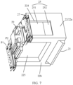
FIG. 7 is a schematic assembling diagram of components other than a second magnet assembly inFIG. 6 ; and -
FIG. 8 is an exploded view of a main structure inFIG. 1 . - A corresponding relationship among drawing signs in
FIG. 1 to FIG. 8 and component names is shown as follows. - 100 Imaging module; 1 Housing; 1a Light-transmitting hole; 3 Lens assembly; 4 Lens motor carrier;
- 2 Prism motor; 20 Base; 21 Prism; 211 Light inlet surface; 212 Light-emitting surface; 213 Reflected light surface; 22 Prism support; 220 Main body; 221 Side wall; 222 Inclined wall; 223 Protruding portion; 224 First groove; 225 Second groove; 226 Cavity; 22a First side surface; 22b Second side surface; 23 First driving coil; 24 Second driving coil; 25 First magnet assembly; 251 First magnet; 252 Second magnet; 26 Second magnet assembly; 27 Elastic piece; 28 Fixing frame; 29 Support body; 291 Extension portion; 30 PCB board; 2-1 Sphere portion; and 2-2 Lining plate.
- In view of technical problems of easy occurrence of jitters, abnormal sounds, and prism assembly errors in a current prism motor during use, intensive studies are performed in this application, and the studies have found that, since a current prism and a prism support fixing the prism are made of different materials, the material of the prism is denser in density, and the prism support is lighter in density, so that the weight of the prism is often greater than the weight of the prism support where the prism is located, causing the overall center of gravity of rotation to tilt to a side of the prism after the prism and the prism support are assembled, then a rotation center is located on the prism support side, the center of gravity does not coincide with the rotation center, and the gravity induces a rotation moment to cause the prism motor to tilt without being energized, easily leading to jitters, abnormal sounds, and prism assembly errors. Meanwhile, the moment of the center of gravity generates a reacting force on a driving force, so that power consumption of the prism motor is increased.
- Based on the above findings, this application provides a technical solution, which can eliminate or reduce the probability of the occurrence of the above technical problems.
- Refer to
FIG. 1 andFIG. 8 .FIG. 1 is an overall schematic diagram of an imaging module according to an embodiment of this application.FIG. 8 is an exploded view of a main structure inFIG. 1 . - An embodiment of this application provides an electronic device. The electronic device includes an
imaging module 100. Theimaging module 100 includes aprism motor 2, alens assembly 3, and a lens motor carrier 4. The lens assembly 3 (covered by a housing 1) is not shown inFIG. 1 . Thelens assembly 3 is located in a right-side position of theprism motor 2 inFIG. 1 . Theprism motor 2 and thelens assembly 3 may be assembled inside thehousing 1, and thehousing 1 mainly plays a role in protecting components located inside the housing. Thehousing 1 is provided with a light-transmitting hole 1a, and external light first enters theprism motor 2 and then enters thelens assembly 3 after being refracted by theprism motor 2. A main light path direction S entering theprism motor 2 and an emergent light path direction S1 after refraction of theprism motor 2 are provided inFIG. 1 , and the light enters the lens assembly in the emergent lightpath direction S 1. For the electronic device, S is usually a thickness direction of the electronic device, and S1 is usually a length direction of the electronic device. - Refer to
FIG. 2 to FIG. 4 .FIG. 2 is a partial three-dimensional schematic diagram of a prism motor inFIG. 1 .FIG. 3 is a cross-sectional view in a direction of A-A inFIG. 2 .FIG. 4 is a schematic assembling diagram of a prism support, a first magnet assembly, and an elastic piece inFIG. 2 . - The
prism motor 2 further includes a base 20, a first driving coil, aprism 21, and aprism support 22. Refer toFIG. 3 . Theprism 21 may be a triple prism. The triple prism is a prism with a cross section being a right-angled triangle. A circumferential surface of the prism includes three surfaces successively connected end to end, which are alight inlet surface 211, a light-emittingsurface 212, and a reflectedlight surface 213. Thelight inlet surface 211 and the light-emittingsurface 212 are usually vertical, and the reflectedlight surface 213 is an inclined surface connected between thelight inlet surface 212 and the light-emittingsurface 212. Only thelight inlet surface 211 is shown inFIG. 2 , and other light surfaces may be understood in combination withFIG. 3 . The fact that three-dimensional structures of other light surfaces are not shown does not prevent a person skilled in the art from understanding the technical solutions herein. The external light enters theprism 21 via the light inlet surface, and is emitted from theprism 21 by the light-emitting surface after being reflected by the reflected light surface. The reflected light surface is usually mounted opposite to aninclined wall 222 of the prism support. Theprism 21 is not limited to the triple prism described here, and may certainly be other forms of prisms, and a main function of the prism is to change a light propagation path to meet requirements for a mounting position of thelens assembly 5. Herein, the technical solutions and technical effects are continuously introduced by using theprism 21 being the triple prism as an example. - Refer to
FIG. 4 . In a specific example, theprism support 22 includes amain body 220. Themain body 220 has twoside walls 221. There is aninclined wall 222 between the twoside walls 221. A mounting space for mounting theprism 21 is enclosed by theinclined wall 222 and the twoside walls 221. For the triple prism, the mounting space is an angular structure matching the triple prism. The reflected light surface of theprism 21 is opposite to theinclined wall 222. FromFIG. 3 to FIG. 6 , it can be seen that most of the structure of theprism 21 may be located in the mounting space that is used for mounting theprism 21 and that is enclosed by theinclined wall 222 and the twoside walls 221, and not theentire prism 21 is completely located inside the mounting space, so that the position of theprism 21 is conveniently adjusted. Definitely, it is not excluded that theentire prism 21 is completely located inside the mounting space, and the position of theprism 21 is conveniently adjusted by reserving enough space between theprism 21 and theprism support 22, so as to achieve an anti-jitter function of the imaging module. - The
prism 21 is fixed on theprism support 22 to form a prism assembly. Theprism 21 may be fixed with theprism support 22 through dispensing. For example, the twoside walls 221 of theprism support 22 are fixed with corresponding side walls of theprism 21 through dispensing. Definitely, fixation between theprism 21 and theprism support 22 is not limited to the description herein, but may be in other ways. - The prism assembly is rotatably supported on the base 20, and generally, the
prism support 22 is rotatably supported on the base 20. That is, theprism support 22 has a rotation center O rotating relative to the base 20 of theprism motor 2. - The prism assembly in this application is configured so that the gravity of the prism assembly is within a theoretical design range relative to the torque of the rotation center O, and the theoretical design range is zero or a numerical range close to zero.
- In this application, by making the gravity of the prism assembly within the theoretical design range relative to the torque of the rotation center O, a static pose difference of the prism motor may be guaranteed, risks of resonance and wobbly impact noise are reduced, and prism assembling precision is improved. Through rational configuration, a moment generated by the center of gravity of the prism assembly may be reduced to almost zero or zero, so that a driving force required by the prism motor is effectively reduced, thus achieving reduction in power consumption.
- In this application, the
prism 21 is made of glass, and theprism support 22 is made of plastic. Definitely, materials of theprism 21 and theprism support 22 are not limited to the description herein. Generally, a material density of theprism support 22 is less than a material density of theprism 21, so that the center of gravity of the entire assembly formed by assembling theprism 21 and theprism support 22 is biased to the side of theprism 21, and not located in the center of the assembly. While the rotation center O is generally located in the central position of the prism assembly, to make the center of gravity of the prism assembly as close to the rotation center as possible, the prism assembly of this application is further disposed as follows. - In an example, the prism assembly further includes a weight component, fixed on a side of the
prism support 22 away from the center of gravity of theprism 21. In this embodiment, the distance between a center of gravity O' of the prism assembly formed by theprism 21, theprism support 22, and the weight component and the rotation center O is small or the center of gravity O' coincides with the rotation center O, so that the gravity of the prism assembly formed by the prism, the prism support, and the weight component is smaller relative to the torque of the rotation center. - In this way, the gravity of the prism assembly can be smaller relative to the torque of the rotation center by additionally adding the weight component on the
current prism support 22, so that improvement costs are low. - Definitely, an ideal state is that the center of gravity O' of the prism assembly coincides with the rotation center O, so that the prism assembly in a static state generates almost no torque to the rotation center O.
- The shape and material of the weight component may be rationally selected according to specific products, and even if structural parameters of the weight component are not disclosed herein, this does not create any obstacle for those skilled in the art to understand and implement the above technical solutions herein. When an anti-jitter function operation is performed on the imaging module, the power that the prism assembly rotates relative to the rotation center O may be derived from the magnet assembly and the driving coil. One of the magnet assembly and the driving coil is mounted on the prism assembly, and the other one is mounted on the base. In other words, the magnet assembly may be mounted to the
prism support 22 of the prism assembly, and may also be mounted on the base 20. Accordingly, the driving coil mated with the magnet assembly may be mounted on the base 20, and may also be mounted on theprism support 22. Herein, the technical solutions and technical effects are continuously introduced by using an example in which the magnet assembly is fixed on theprism support 22 of the prism assembly. - In an embodiment, the prism assembly further includes the magnet assembly fixed on the
prism support 22 and configured to be mated with the driving coil of the prism motor to drive the prism assembly to rotate around the rotation center O. When the driving coil is energized, a driving force is generated between the driving coil and the magnet assembly, and under the action of the driving force, the prism assembly may rotate relative to the rotation center. The direction of the driving force may be changed by changing a direction of a current introduced into the driving coil. The driving coil generally includes a first end and a second end that are electrically connected with an external current. If a current introduced from the first end is defined as a forward current, and a current introduced from the second end is a reverse current, when the forward current is introduced into the driving coil, a first driving force making the prism assembly rotate clockwise is generated by the driving coil and the magnet assembly, and when the reverse current is introduced into the driving coil, a second driving force making the prism assembly rotate anticlockwise is generated by the driving coil and the magnet assembly. The direction of the first driving force is opposite to the direction of the second driving force, and the magnitudes of the first driving force and the second driving force may be controlled by the magnitude of the introduced current. - In this embodiment, the weight component is the magnet assembly.
- There may be more than one group of the driving coils and the magnet assemblies, and an assembly formed by the driving coil and the magnet assembly is defined as a driving coil assembly herein. According to different mounting positions, the driving coil assembly may include a first driving coil assembly and a second driving coil assembly. The first driving coil assembly is configured to drive the prism assembly to rotate around a first axis Z1, and the second driving coil assembly is configured to drive the prism assembly to rotate around a second axis. The first driving coil assembly is located on a
first side surface 22a of the prism assembly, and the second driving coil assembly is located on asecond side surface 22b of the prism assembly. The first axis is not parallel to the second axis. - The prism assembly in this application can rotate around the first axis Z1 and the second axis Z2 under the driving of the first driving coil assembly and the second driving coil assembly, respectively, and the first driving coil assembly and the second driving coil assembly only occupy two side surface spaces of the prism assembly, so that a design space of a motor is saved, the size of the motor is reduced, and the cost and process difficulty of the motor are reduced.
- Refer to
FIG. 3 . In this application, the first axis Z1 is parallel to the light inlet main axis S of the prism assembly, that is, the prism assembly can rotate around a direction parallel to the light inlet main axis S. In the ideal state, the first axis Z1 coincides with the light inlet main axis S. Considering privacy such as assembling errors, the first axis Z1 may not coincide with the light inlet main axis S, and under the driving of the first driving coil assembly, the prism assembly can rotate a predetermined angle around the first axis Z1. - In this application, the second axis Z2 is perpendicular to a plane determined by the light inlet main axis S and the light-emitting main axis S1 of the prism assembly, that is, the prism assembly may rotate around a point O in a cross section shown in
FIG. 3 . In other words, under the driving of the second driving coil assembly, the prism assembly may clockwise or anticlockwise rotate, in a pitching manner, the predetermined angle around the point O in the cross section (a vertical plane) shown inFIG. 3 . - In an example, the first driving coil assembly includes a
first driving coil 23 and afirst magnet assembly 25. One of the first driving coil and the first magnet assembly is fixed on the base 20, and the other one is fixed on the prism assembly. In the drawings, specific implementations that thefirst driving coil 23 is fixed on the base 20 (the base is not shown, but those skilled in the art are not prevented from understanding the technical solutions herein), and thefirst magnet assembly 25 is fixed on theprism support 22 are shown. Definitely, thefirst driving coil 23 is also fixed on theprism support 22, and thefirst magnet assembly 25 is fixed on the base 20.FIG. 2 shows a rough direction of a driving force F generated by a current introduced by thefirst driving coil 23. Thefirst magnet assembly 25 may include a magnet, and may certainly have two or more magnets, and a specific example of including two magnets is provided below. - In an example, the
first magnet assembly 25 includes afirst magnet 251 and asecond magnet 252, and the volume of thefirst magnet 251 is greater than the volume of thesecond magnet 252, so that the weight of thefirst magnet 251 is greater than the weight of thesecond magnet 252. Because thefirst magnet 251 is located on a side of thesecond magnet 252 away from the light-emittingsurface 22 of theprism 21, in combination withFIG. 3 for understanding, for the triple prism, thelight inlet surface 211 is perpendicular to the light-emittingsurface 212, the refractingsurface 213 is an inclined surface, and the refractingsurface 213 is mounted and positioned opposite to a protrudingportion 223 of theprism support 22. FromFIG. 4 , it can be seen that a protruding portion 223 (the protruding portion at a left lower corner is not shown) is disposed on each of four corners of theinclined wall 222 of theprism support 22, the refractingsurface 213 of theprism 21 is partially attached to and fixed with the protrudingportion 223, and there are gaps between other positions of the refractingsurface 213 of theprism 21 and the inclined wall, as shown inFIG. 3 . Torque generated by thefirst magnet 251 and thesecond magnet 252 relative to the rotation center O and the torque of the gravity of theprism support 22 and theprism 21 relative to the rotation center O are same in magnitude, and different in direction. - The
first magnet 251 and thesecond magnet 252 are generally cuboids; thefirst magnet 251 and thesecond magnet 252 are the cuboids with a thickness; and the sizes of adj acent sides of thefirst magnet 251 and thesecond magnet 252 are the same, and the size of the other side of thefirst magnet 251 is greater than the size of the other side of thesecond magnet 252. That is to say, when the thicknesses of thefirst magnet 251 and thesecond magnet 252 are the same, the sizes of the sides are the same, and different sizes may be realized by configuring the sizes of the other sides. - Understanding in combination with
FIG. 5 andFIG. 6 ,FIG. 5 is a schematic assembling diagram of some components inFIG. 2 ; andFIG. 6 is a schematic diagram in which the driving coil inFIG. 5 is deleted. For thefirst magnet assembly 25 mounted on thefirst side surface 22a, first sides of thefirst magnet 251 and thesecond magnet 252 in an S direction and thicknesses and sizes along S2 are the same, and the difference only lies in that the sizes of second sides in anS 1 direction are different. Likewise, the sizes of the first sides of thefirst magnet 251 and thesecond magnet 252 in thesecond magnet assembly 26 in an S2 direction are the same, thicknesses in the S direction are the same, and the difference lies in that the sizes of the second sides of the first magnet and the second magnet in the S1 direction are different. - Definitely, the
first magnet 251 and thesecond magnet 252 may also be in other shapes, as long as the above technical effects can be realized. - In this embodiment, the magnet assembly serves as the weight component, so that the above technical problems in the prior art may be solved without adding redundant components.
- The prism is the triple prism; there are two magnet assemblies, which are respectively located on a first side surface and a second side surface of the prism support that are perpendicular to each other. The first driving coil is mated with the first magnet assembly to generate a driving force making the prism assembly rotate around the light inlet main axis; the second driving coil is mated with the second magnet assembly to generate a driving force making the prism assembly rotate around the second axis perpendicular to the plane that is determined by the light inlet main axis and the light-emitting main axis; the second side surface is perpendicular to the light inlet main axis of the prism; and the first side surface is parallel to an end surface of the prism.
- The
first driving coil 23 may generate an acting force with thefirst magnet assembly 25 after being energized, so as to make theprism support 22 rotate around the first axis Z1. - Definitely, what is mated with the
first driving coil 23 to generate the acting force is not limited to magnets, and may also be other magnetic field components that can generate a magnetic field. - In this application, the second driving coil assembly includes a
second driving coil 24 and asecond magnet assembly 26; and one of the second driving coil and the second magnet assembly is fixed on the base, and the other one is fixed on the prism assembly. Specific implementations that the second driving coil is fixed on the base and the second magnet assembly is fixed on the prism support are shown inFIG. 3 , and definitely, the second driving coil is also fixed on the prism support, and the second magnet assembly is fixed on the base. In an example, the second magnet assembly includes a first magnet and a second magnet, and the two magnets may be same in size, and may also be different in size, definitely. - The
second driving coil 24 may generate an acting force with thesecond magnet assembly 26 after being energized, so as to make theprism support 22 rotate around the second axis Z2. - Refer to
FIG. 7 . Thefirst side surface 22a and thesecond side surface 22b of the prism support may be two surfaces perpendicular to each other; and thefirst side surface 22a and thesecond side surface 22b may be respectively provided with afirst groove 224 and a second groove, which are respectively configured to mount the first magnet assembly and the second magnet assembly. - Definitely, what is mated with the
second driving coil 24 to generate the acting force is not limited to magnets, and may also be other magnetic field components that can generate a magnetic field. - In this application, the
prism support 22 and the base 20 are spherically supported, and theprism support 22 rotates around a spherical support position. - Further refer to
FIG. 3 . In an example, the prism assembly further includes asupport body 29 fixedly connected to the base 20; thesupport body 29 is provided with anextension portion 291 parallel to the light-emitting main axis S1 of the prism; and theextension portion 291 at least partially extends into theprism support 22 and is spherically supported with theprism support 22. It is to be noted that, the extending of theabove extension portion 291 parallel to the light-emitting main axis S1 only indicates a rough direction of the length of the extension portion S1, and is not absolutely parallel to the light-emitting main axis S1. Specifically, theprism support 22 may be provided with acavity 226 with an opening towards the extension portion; and theextension portion 291 is inserted into thecavity 226 from the opening and is in spherical contact with an inner wall of thecavity 226. Specifically, a right end portion of theextension portion 291 spherically bears against the corresponding inner wall of thecavity 226, so that thesupport body 29 may relatively rotate around a spherical contact position of theprism support 22. - Specifically, one of the end portion of the
extension portion 291 and the inner wall of thecavity 226 may be provided with a sphere portion 2-1, and the other one is provided with a concave portion mated with the sphere portion 2-1.FIG. 3 shows a specific implementation of theextension portion 291 provided with the sphere portion 2-1. The fixation mode is relatively simple in structure, and is easy to implement. Definitely, the sphere 2-1 may also be fixed on the inner wall of thecavity 226. - In order to improve the stability of the positioning of the prism assembly, the prism assembly further includes an elastic tensioning member; and the elastic tensioning member is tensioned between the base 20 and the
prism support 22, so as to make theprism support 22 bear against thesupport body 29. Specifically, the elastic tensioning member includes an elastic piece. Two ends of the elastic piece are fixedly connected with two side walls of the prism support, and a middle region is fixedly connected with the prism support.FIG. 6 shows the position of the elastic piece when being at a P1 position and a P2 position; and only partial structure, which is connected with the base, of the elastic piece at the P1 position is shown. The partial structure of theelastic piece 27 at the P1 position inFIG. 4 to FIG. 7 is shown with dashed lines; and showing the partial structure of theelastic piece 27 at the P1 position is mainly based on clear identifiers of the entire view, and the showing of two positions of the elastic piece does not affect the marking of the entire structure of the view, facilitating the understanding of the technical solutions by those skilled in the art. - The
elastic piece 27 may be made of a material having an elastic deformation capacity, such as a leaf spring, as long as an elastic force meeting use requirements can be provided. - In addition, the prism motor further includes a
PCB 30 electrically connected with thefirst driving coil 23 and thesecond driving coil 24. - In addition, an abrasion-resistant lining plate 2-2 may also be added between the
support body 29 and theprism support 22. The lining plate 2-2 is fixed in thecavity 226, and theextension portion 291 is in spherical contact with the lining plate 2-2. In this way, abrasions of the extension portion to theprism support 22 may be reduced as much as possible. The lining plate 2-2 may be fixed in thecavity 226 through bonding. Positions that thesupport body 29 may be in contact with theprism support 22 during rotation may all be provided with the lining plates 2-2, so as to reduce the abrasions to theprism support 22 as much as possible; a specific structure of the lining plate 2-2 may be specifically determined according to products; and the understanding and implementation of the technical solutions by those skilled in the art are not affected without disclosing the shape of the lining plate 2-2 herein. -
FIG. 3 shows that the lining plate 2-2 is roughly of an L-shaped structure, and the sphere 2-1 mounted on a right end of theextension portion 291 is spherically mated with a vertical wall of the lining plate 2-2. - According to a second aspect, this application further provides a prism motor, including a base and the prism assembly described in any one of the above.
- According to a third aspect, this application further provides an electronic device, including the prism motor described in any one of the above.
- The prism motor and the electronic device of this application include the prism assembly, and thus have the above technical effects of the prism assembly.
- The electronic device of the embodiments may include, but is not limited to, a mobile phone, and may also be other electronic devices, as long as the electronic device has a need for photographic functions, which may all use the solution. For example, the electronic device may include a notebook computer, and may also include mobile terminals such as a wearable device, a vehicle device, an augmented reality (augmented reality, AR)/virtual reality (virtual reality, VR) device, an ultra-mobile personal computer (ultra-mobile personal computer, UMPC), a Netbook, a personal digital assistant (personal digital assistant, PDA), or may also include professional photographing devices such as a digital camera, a single lens reflective camera/mirrorless camera, a motion camera, a gimbal camera, an unmanned aerial vehicle, etc.
- The principle and implementations of this application are described herein through specific examples. The descriptions of the foregoing embodiments are merely used for helping understand the method and core ideas of this application. It should be noted that a person of ordinary skill in the art may further make several improvements and modifications to this application without departing from the principle of this application. These improvements and modifications also fall within the protection scope of the claims of this application.
Claims (10)
- A prism assembly of a prism motor, comprising at least a prism and a prism support, wherein the prism support has a rotation center rotating relative to a base of a prism motor, the prism assembly is configured so that gravity of the prism assembly is within a theoretical design range relative to torque of the rotation center, and the theoretical design range is zero or a numerical range close to zero.
- The prism assembly according to claim 1, wherein a center of gravity of the prism assembly coincides with the rotation center.
- The prism assembly according to claim 1 or 2, wherein a material density of the prism support is less than a material density of the prism, and the prism assembly further comprises a weight component fixed on a side of the prism support away from the center of gravity of the prism.
- The prism assembly according to claim 2, wherein the prism assembly further comprises a magnet assembly fixed on the prism support and configured to be mated with a driving coil of the prism motor to drive the prism assembly to rotate around the rotation center; and the weight component is the magnet assembly.
- The prism assembly according to claim 4, wherein the magnet assembly comprises a first magnet and a second magnet, the volume of the first magnet is greater than the volume of the second magnet, and the first magnet is located on a side of the second magnet away from a light-emitting surface of the prism.
- The prism assembly according to claim 5, wherein the first magnet and the second magnet are cuboids with a thickness, the sizes of adjacent sides of the first magnet and the second magnet are the same, and the size of the other side of the first magnet is greater than the size of the other side of the second magnet.
- The prism assembly according to any one of claims 4 to 6, wherein there are two magnet assemblies, respectively located on a first side surface and a second side surface of the prism support that are perpendicular to each other, the prism is a triple prism, the second side surface is perpendicular to a light inlet main axis of the prism, and the first side surface is parallel to an end surface of the prism.
- The prism assembly according to any one of claims 1 to 7, wherein the prism is made of glass, and the prism support is made of plastic.
- A prism motor, comprising a base, and the prism assembly according to any one of claims 1 to 8.
- An electronic device, comprising the prism motor according to claim 9.
Applications Claiming Priority (3)
| Application Number | Priority Date | Filing Date | Title |
|---|---|---|---|
| CN202210209454 | 2022-03-03 | ||
| CN202210570009.0A CN116736474B (en) | 2022-03-03 | 2022-05-24 | A prism assembly, a prism motor and an electronic device |
| PCT/CN2023/071276 WO2023165267A1 (en) | 2022-03-03 | 2023-01-09 | Prism assembly, prism motor, and electronic device |
Publications (2)
| Publication Number | Publication Date |
|---|---|
| EP4390492A1 true EP4390492A1 (en) | 2024-06-26 |
| EP4390492A4 EP4390492A4 (en) | 2025-01-29 |
Family
ID=87883021
Family Applications (1)
| Application Number | Title | Priority Date | Filing Date |
|---|---|---|---|
| EP23762668.4A Pending EP4390492A4 (en) | 2022-03-03 | 2023-01-09 | Prism assembly, prism motor, and electronic device |
Country Status (3)
| Country | Link |
|---|---|
| EP (1) | EP4390492A4 (en) |
| CN (4) | CN118829923B (en) |
| WO (1) | WO2023165267A1 (en) |
Cited By (1)
| Publication number | Priority date | Publication date | Assignee | Title |
|---|---|---|---|---|
| EP4535058A4 (en) * | 2022-05-31 | 2025-10-15 | Shanghai B L Electronics Co Ltd | PERISCOPE LENS DRIVE DEVICE, CAMERA DEVICE AND MOBILE TERMINAL |
Family Cites Families (13)
| Publication number | Priority date | Publication date | Assignee | Title |
|---|---|---|---|---|
| JP3193668B2 (en) * | 1997-06-17 | 2001-07-30 | 旭光学工業株式会社 | Transmission type optical deflection device |
| JP2006113297A (en) * | 2004-10-14 | 2006-04-27 | Seiko Epson Corp | Optical scanning device and projector |
| US7974009B2 (en) * | 2007-09-19 | 2011-07-05 | Victor Company Of Japan, Limited | Image fluctuation correcting apparatus |
| KR102581599B1 (en) * | 2018-05-11 | 2023-09-25 | 엘지전자 주식회사 | Prism module, camera, and image display apparatus including the same |
| EP4249969A3 (en) * | 2018-12-27 | 2024-01-10 | Tdk Taiwan Corp. | Optical member driving mechanism |
| WO2020243856A1 (en) * | 2019-06-01 | 2020-12-10 | 瑞声光学解决方案私人有限公司 | Prism module and periscope camera |
| CN110764217A (en) * | 2019-11-07 | 2020-02-07 | 河南皓泽电子股份有限公司 | Prism driving device and prism assembly |
| CN110967803A (en) * | 2019-12-31 | 2020-04-07 | 上海比路电子股份有限公司 | Prism motor and imaging system |
| CN113194216B (en) * | 2020-01-14 | 2023-12-15 | 华为机器有限公司 | Voice coil motor, lens module and electronic equipment |
| CN211741798U (en) * | 2020-03-13 | 2020-10-23 | 北京可利尔福科技有限公司 | Elastic element and mounting structure thereof |
| CN115918098A (en) * | 2020-07-21 | 2023-04-04 | Lg伊诺特有限公司 | Camera actuator and camera module including the same |
| CN113467042B (en) * | 2021-07-18 | 2023-07-18 | 新思考电机有限公司 | Anti-shake mechanism, prism drive, camera device and electronic equipment |
| CN116736474B (en) * | 2022-03-03 | 2024-08-09 | 荣耀终端有限公司 | A prism assembly, a prism motor and an electronic device |
-
2023
- 2023-01-09 CN CN202380025334.1A patent/CN118829923B/en active Active
- 2023-01-09 CN CN202510934573.XA patent/CN121028321A/en active Pending
- 2023-01-09 EP EP23762668.4A patent/EP4390492A4/en active Pending
- 2023-01-09 CN CN202510934133.4A patent/CN120722533A/en active Pending
- 2023-01-09 CN CN202510165220.8A patent/CN120161584A/en active Pending
- 2023-01-09 WO PCT/CN2023/071276 patent/WO2023165267A1/en not_active Ceased
Cited By (1)
| Publication number | Priority date | Publication date | Assignee | Title |
|---|---|---|---|---|
| EP4535058A4 (en) * | 2022-05-31 | 2025-10-15 | Shanghai B L Electronics Co Ltd | PERISCOPE LENS DRIVE DEVICE, CAMERA DEVICE AND MOBILE TERMINAL |
Also Published As
| Publication number | Publication date |
|---|---|
| WO2023165267A1 (en) | 2023-09-07 |
| CN118829923B (en) | 2025-07-29 |
| CN118829923A (en) | 2024-10-22 |
| CN120161584A (en) | 2025-06-17 |
| EP4390492A4 (en) | 2025-01-29 |
| CN120722533A (en) | 2025-09-30 |
| CN121028321A (en) | 2025-11-28 |
Similar Documents
| Publication | Publication Date | Title |
|---|---|---|
| CN112887456B (en) | Imaging module, camera assembly and electronic device | |
| CN114114588B (en) | Reflex module and camera module for optical image stabilization | |
| CN109274877B (en) | Imaging module, camera assembly and electronic device | |
| CN112532816B (en) | Periscopic camera module and electronic equipment | |
| CN215642016U (en) | Optical element driving mechanism | |
| CN112578608A (en) | Optical anti-shake module and camera module including the same | |
| CN108769493A (en) | CCD camera assembly and electronic device | |
| US20210124145A1 (en) | Camera Module, Camera Assembly, and Electronic Device | |
| CN110062071B (en) | Periscopic lens, imaging module, camera assembly and electronic device | |
| CN108769325A (en) | Electronic device | |
| CN111308643A (en) | Camera module, periscope camera module, camera assembly and electronic device | |
| EP4390492A1 (en) | Prism assembly, prism motor, and electronic device | |
| CN209151242U (en) | Imaging module, camera assembly and electronic device | |
| CN117134571B (en) | Driving motor, camera module and electronic equipment | |
| CN108769492A (en) | CCD camera assembly and electronic device | |
| EP4350411A1 (en) | Optical lens, photographing module and electronic device | |
| CN110062141B (en) | Light conversion device, imaging module, camera assembly and electronic device | |
| CN108777761B (en) | Imaging modules and electronic devices | |
| CN116736474B (en) | A prism assembly, a prism motor and an electronic device | |
| CN209151241U (en) | Imaging module, camera assembly and electronic device | |
| CN218383444U (en) | Prism motor and electronic equipment | |
| CN109167908B (en) | Imaging module, camera assembly and electronic device | |
| WO2021023067A1 (en) | Imaging apparatus and electronic device | |
| CN113114823A (en) | Imaging module, camera assembly and electronic device | |
| CN109639939A (en) | Electronic device |
Legal Events
| Date | Code | Title | Description |
|---|---|---|---|
| STAA | Information on the status of an ep patent application or granted ep patent |
Free format text: STATUS: THE INTERNATIONAL PUBLICATION HAS BEEN MADE |
|
| PUAI | Public reference made under article 153(3) epc to a published international application that has entered the european phase |
Free format text: ORIGINAL CODE: 0009012 |
|
| STAA | Information on the status of an ep patent application or granted ep patent |
Free format text: STATUS: REQUEST FOR EXAMINATION WAS MADE |
|
| 17P | Request for examination filed |
Effective date: 20240321 |
|
| AK | Designated contracting states |
Kind code of ref document: A1 Designated state(s): AL AT BE BG CH CY CZ DE DK EE ES FI FR GB GR HR HU IE IS IT LI LT LU LV MC ME MK MT NL NO PL PT RO RS SE SI SK SM TR |
|
| A4 | Supplementary search report drawn up and despatched |
Effective date: 20250108 |
|
| RIC1 | Information provided on ipc code assigned before grant |
Ipc: H02K 41/035 20060101ALI20241223BHEP Ipc: G02B 26/08 20060101ALI20241223BHEP Ipc: G02B 7/18 20210101AFI20241223BHEP |
|
| DAV | Request for validation of the european patent (deleted) | ||
| DAX | Request for extension of the european patent (deleted) | ||
| STAA | Information on the status of an ep patent application or granted ep patent |
Free format text: STATUS: EXAMINATION IS IN PROGRESS |
|
| GRAP | Despatch of communication of intention to grant a patent |
Free format text: ORIGINAL CODE: EPIDOSNIGR1 |
|
| STAA | Information on the status of an ep patent application or granted ep patent |
Free format text: STATUS: GRANT OF PATENT IS INTENDED |
|
| 17Q | First examination report despatched |
Effective date: 20250916 |
|
| GRAJ | Information related to disapproval of communication of intention to grant by the applicant or resumption of examination proceedings by the epo deleted |
Free format text: ORIGINAL CODE: EPIDOSDIGR1 |
|
| STAA | Information on the status of an ep patent application or granted ep patent |
Free format text: STATUS: EXAMINATION IS IN PROGRESS |
|
| INTG | Intention to grant announced |
Effective date: 20251029 |
|
| GRAP | Despatch of communication of intention to grant a patent |
Free format text: ORIGINAL CODE: EPIDOSNIGR1 |
|
| STAA | Information on the status of an ep patent application or granted ep patent |
Free format text: STATUS: GRANT OF PATENT IS INTENDED |
|
| INTC | Intention to grant announced (deleted) | ||
| GRAJ | Information related to disapproval of communication of intention to grant by the applicant or resumption of examination proceedings by the epo deleted |
Free format text: ORIGINAL CODE: EPIDOSDIGR1 |
|
| STAA | Information on the status of an ep patent application or granted ep patent |
Free format text: STATUS: EXAMINATION IS IN PROGRESS |
|
| INTG | Intention to grant announced |
Effective date: 20251216 |
|
| GRAP | Despatch of communication of intention to grant a patent |
Free format text: ORIGINAL CODE: EPIDOSNIGR1 |
|
| STAA | Information on the status of an ep patent application or granted ep patent |
Free format text: STATUS: GRANT OF PATENT IS INTENDED |
|
| INTC | Intention to grant announced (deleted) | ||
| INTG | Intention to grant announced |
Effective date: 20260129 |