EP4390419A1 - Battery capacity estimation method and apparatus, and computer storage medium - Google Patents
Battery capacity estimation method and apparatus, and computer storage medium Download PDFInfo
- Publication number
- EP4390419A1 EP4390419A1 EP22897312.9A EP22897312A EP4390419A1 EP 4390419 A1 EP4390419 A1 EP 4390419A1 EP 22897312 A EP22897312 A EP 22897312A EP 4390419 A1 EP4390419 A1 EP 4390419A1
- Authority
- EP
- European Patent Office
- Prior art keywords
- battery
- capacity
- voltage
- curve
- charging
- Prior art date
- Legal status (The legal status is an assumption and is not a legal conclusion. Google has not performed a legal analysis and makes no representation as to the accuracy of the status listed.)
- Granted
Links
Images
Classifications
-
- H—ELECTRICITY
- H01—ELECTRIC ELEMENTS
- H01M—PROCESSES OR MEANS, e.g. BATTERIES, FOR THE DIRECT CONVERSION OF CHEMICAL ENERGY INTO ELECTRICAL ENERGY
- H01M10/00—Secondary cells; Manufacture thereof
- H01M10/05—Accumulators with non-aqueous electrolyte
- H01M10/052—Li-accumulators
-
- G—PHYSICS
- G01—MEASURING; TESTING
- G01R—MEASURING ELECTRIC VARIABLES; MEASURING MAGNETIC VARIABLES
- G01R31/00—Arrangements for testing electric properties; Arrangements for locating electric faults; Arrangements for electrical testing characterised by what is being tested not provided for elsewhere
- G01R31/36—Arrangements for testing, measuring or monitoring the electrical condition of accumulators or electric batteries, e.g. capacity or state of charge [SoC]
- G01R31/382—Arrangements for monitoring battery or accumulator variables, e.g. SoC
- G01R31/3835—Arrangements for monitoring battery or accumulator variables, e.g. SoC involving only voltage measurements
-
- G—PHYSICS
- G01—MEASURING; TESTING
- G01R—MEASURING ELECTRIC VARIABLES; MEASURING MAGNETIC VARIABLES
- G01R19/00—Arrangements for measuring currents or voltages or for indicating presence or sign thereof
- G01R19/165—Indicating that current or voltage is either above or below a predetermined value or within or outside a predetermined range of values
- G01R19/16528—Indicating that current or voltage is either above or below a predetermined value or within or outside a predetermined range of values using digital techniques or performing arithmetic operations
-
- G—PHYSICS
- G01—MEASURING; TESTING
- G01R—MEASURING ELECTRIC VARIABLES; MEASURING MAGNETIC VARIABLES
- G01R19/00—Arrangements for measuring currents or voltages or for indicating presence or sign thereof
- G01R19/165—Indicating that current or voltage is either above or below a predetermined value or within or outside a predetermined range of values
- G01R19/16533—Indicating that current or voltage is either above or below a predetermined value or within or outside a predetermined range of values characterised by the application
- G01R19/16538—Indicating that current or voltage is either above or below a predetermined value or within or outside a predetermined range of values characterised by the application in AC or DC supplies
- G01R19/16542—Indicating that current or voltage is either above or below a predetermined value or within or outside a predetermined range of values characterised by the application in AC or DC supplies for batteries
-
- G—PHYSICS
- G01—MEASURING; TESTING
- G01R—MEASURING ELECTRIC VARIABLES; MEASURING MAGNETIC VARIABLES
- G01R31/00—Arrangements for testing electric properties; Arrangements for locating electric faults; Arrangements for electrical testing characterised by what is being tested not provided for elsewhere
- G01R31/36—Arrangements for testing, measuring or monitoring the electrical condition of accumulators or electric batteries, e.g. capacity or state of charge [SoC]
- G01R31/367—Software therefor, e.g. for battery testing using modelling or look-up tables
-
- G—PHYSICS
- G01—MEASURING; TESTING
- G01R—MEASURING ELECTRIC VARIABLES; MEASURING MAGNETIC VARIABLES
- G01R31/00—Arrangements for testing electric properties; Arrangements for locating electric faults; Arrangements for electrical testing characterised by what is being tested not provided for elsewhere
- G01R31/36—Arrangements for testing, measuring or monitoring the electrical condition of accumulators or electric batteries, e.g. capacity or state of charge [SoC]
- G01R31/374—Arrangements for testing, measuring or monitoring the electrical condition of accumulators or electric batteries, e.g. capacity or state of charge [SoC] with means for correcting the measurement for temperature or ageing
-
- G—PHYSICS
- G01—MEASURING; TESTING
- G01R—MEASURING ELECTRIC VARIABLES; MEASURING MAGNETIC VARIABLES
- G01R31/00—Arrangements for testing electric properties; Arrangements for locating electric faults; Arrangements for electrical testing characterised by what is being tested not provided for elsewhere
- G01R31/36—Arrangements for testing, measuring or monitoring the electrical condition of accumulators or electric batteries, e.g. capacity or state of charge [SoC]
- G01R31/378—Arrangements for testing, measuring or monitoring the electrical condition of accumulators or electric batteries, e.g. capacity or state of charge [SoC] specially adapted for the type of battery or accumulator
-
- G—PHYSICS
- G01—MEASURING; TESTING
- G01R—MEASURING ELECTRIC VARIABLES; MEASURING MAGNETIC VARIABLES
- G01R31/00—Arrangements for testing electric properties; Arrangements for locating electric faults; Arrangements for electrical testing characterised by what is being tested not provided for elsewhere
- G01R31/36—Arrangements for testing, measuring or monitoring the electrical condition of accumulators or electric batteries, e.g. capacity or state of charge [SoC]
- G01R31/382—Arrangements for monitoring battery or accumulator variables, e.g. SoC
- G01R31/3842—Arrangements for monitoring battery or accumulator variables, e.g. SoC combining voltage and current measurements
-
- G—PHYSICS
- G01—MEASURING; TESTING
- G01R—MEASURING ELECTRIC VARIABLES; MEASURING MAGNETIC VARIABLES
- G01R31/00—Arrangements for testing electric properties; Arrangements for locating electric faults; Arrangements for electrical testing characterised by what is being tested not provided for elsewhere
- G01R31/36—Arrangements for testing, measuring or monitoring the electrical condition of accumulators or electric batteries, e.g. capacity or state of charge [SoC]
- G01R31/385—Arrangements for measuring battery or accumulator variables
- G01R31/387—Determining ampere-hour charge capacity or SoC
- G01R31/388—Determining ampere-hour charge capacity or SoC involving voltage measurements
-
- G—PHYSICS
- G01—MEASURING; TESTING
- G01R—MEASURING ELECTRIC VARIABLES; MEASURING MAGNETIC VARIABLES
- G01R31/00—Arrangements for testing electric properties; Arrangements for locating electric faults; Arrangements for electrical testing characterised by what is being tested not provided for elsewhere
- G01R31/36—Arrangements for testing, measuring or monitoring the electrical condition of accumulators or electric batteries, e.g. capacity or state of charge [SoC]
- G01R31/392—Determining battery ageing or deterioration, e.g. state of health
-
- H—ELECTRICITY
- H01—ELECTRIC ELEMENTS
- H01M—PROCESSES OR MEANS, e.g. BATTERIES, FOR THE DIRECT CONVERSION OF CHEMICAL ENERGY INTO ELECTRICAL ENERGY
- H01M10/00—Secondary cells; Manufacture thereof
- H01M10/42—Methods or arrangements for servicing or maintenance of secondary cells or secondary half-cells
- H01M10/44—Methods for charging or discharging
-
- H—ELECTRICITY
- H02—GENERATION; CONVERSION OR DISTRIBUTION OF ELECTRIC POWER
- H02J—ELECTRIC POWER NETWORKS; CIRCUIT ARRANGEMENTS OR SYSTEMS FOR SUPPLYING OR DISTRIBUTING ELECTRIC POWER; SYSTEMS FOR STORING ELECTRIC ENERGY
- H02J7/00—Circuit arrangements for charging or discharging batteries or for supplying loads from batteries
- H02J7/80—Circuit arrangements for charging or discharging batteries or for supplying loads from batteries including monitoring or indicating arrangements
- H02J7/82—Control of state of charge [SOC]
- H02J7/825—Detection of fully charged condition
-
- H—ELECTRICITY
- H02—GENERATION; CONVERSION OR DISTRIBUTION OF ELECTRIC POWER
- H02J—ELECTRIC POWER NETWORKS; CIRCUIT ARRANGEMENTS OR SYSTEMS FOR SUPPLYING OR DISTRIBUTING ELECTRIC POWER; SYSTEMS FOR STORING ELECTRIC ENERGY
- H02J7/00—Circuit arrangements for charging or discharging batteries or for supplying loads from batteries
- H02J7/80—Circuit arrangements for charging or discharging batteries or for supplying loads from batteries including monitoring or indicating arrangements
- H02J7/84—Control of state of health [SOH]
-
- H—ELECTRICITY
- H01—ELECTRIC ELEMENTS
- H01M—PROCESSES OR MEANS, e.g. BATTERIES, FOR THE DIRECT CONVERSION OF CHEMICAL ENERGY INTO ELECTRICAL ENERGY
- H01M10/00—Secondary cells; Manufacture thereof
- H01M10/05—Accumulators with non-aqueous electrolyte
- H01M10/052—Li-accumulators
- H01M10/0525—Rocking-chair batteries, i.e. batteries with lithium insertion or intercalation in both electrodes; Lithium-ion batteries
-
- H—ELECTRICITY
- H01—ELECTRIC ELEMENTS
- H01M—PROCESSES OR MEANS, e.g. BATTERIES, FOR THE DIRECT CONVERSION OF CHEMICAL ENERGY INTO ELECTRICAL ENERGY
- H01M2220/00—Batteries for particular applications
- H01M2220/20—Batteries in motive systems, e.g. vehicle, ship, plane
-
- Y—GENERAL TAGGING OF NEW TECHNOLOGICAL DEVELOPMENTS; GENERAL TAGGING OF CROSS-SECTIONAL TECHNOLOGIES SPANNING OVER SEVERAL SECTIONS OF THE IPC; TECHNICAL SUBJECTS COVERED BY FORMER USPC CROSS-REFERENCE ART COLLECTIONS [XRACs] AND DIGESTS
- Y02—TECHNOLOGIES OR APPLICATIONS FOR MITIGATION OR ADAPTATION AGAINST CLIMATE CHANGE
- Y02E—REDUCTION OF GREENHOUSE GAS [GHG] EMISSIONS, RELATED TO ENERGY GENERATION, TRANSMISSION OR DISTRIBUTION
- Y02E60/00—Enabling technologies; Technologies with a potential or indirect contribution to GHG emissions mitigation
- Y02E60/10—Energy storage using batteries
Definitions
- the present disclosure relates to the technical field of battery management, and more specifically to a battery capacity estimation method and apparatus, and a computer storage medium.
- SOH State Of Health
- the main method is implemented by calculating the total electric quantity during the charging or discharging stage by fully charging and discharging the battery, or by charging and discharging within a certain State of Charge (SOC) range of the battery, and calculating the total battery capacity based on the charging or discharging electric quantity and the corresponding SOC range.
- SOC State of Charge
- the estimation accuracy in this method depends entirely on the accuracy of SOC. If there is a significant error in SOC estimation, it will affect the battery capacity estimation accuracy Especially for lithium iron phosphate batteries, the cumulative error of SOC will affect the accuracy of battery capacity. However, the error of the battery capacity can in turn affect the accuracy of SOC, leading to cross effects and ultimately rendering the estimation of battery capacity completely ineffective.
- the capacity of the battery is estimated according to the voltage knee point on the voltage-capacity curve in the battery charging process, the estimation accuracy of the battery capacity may be improved, the battery does not need to be emptied, and the using habit of a user is met.
- the method before the performing differentiation on the voltage-capacity curve, the method further includes performing smoothing filtering on the voltage-capacity curve.
- the method further includes: a state of health of the battery is estimated according to the actual capacity and a pre-calibrated initial capacity of the battery.
- the battery is a lithium iron phosphate battery.
- the initial capacity of the battery is determined by the following mode: the electric quantity of the battery is emptied and then constant-current charging is performed until reaching the full-charge state; and the initial capacity of the battery is recorded.
- an embodiment of the present disclosure provides a battery capacity estimation apparatus, including a memory and a processor.
- a computer program operated with the processor is stored in the memory, and the computer program executes the battery capacity estimation method when being operated with the processor.
- the capacity of the battery is estimated according to the voltage knee point on the voltage-capacity curve in the battery charging process, and the absolute value of SOC is not involved. Therefore, the estimation accuracy of the battery capacity may be improved, the battery does not need to be emptied, and the using habit of the user is met.
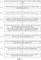
- FIG. 1 is a schematic flowchart of a battery capacity estimation method according to an embodiment of the present disclosure. As shown in FIG. 1 , the battery capacity estimation method includes:
- S110 A voltage-capacity curve of a battery is acquired in real time in a battery charging process.
- S140 A first height and a first width between each wave crest and an adjacent wave trough on the left, and a second height and a second width between each wave crest and an adjacent wave trough on the right are calculated.
- a voltage knee point in the voltage-capacity curve is determined according to a wave crest with a minimum determination index.
- S170 A pre-calibrated reference capacity value corresponding to the voltage knee point in the voltage-capacity curve is acquired.
- the voltage-battery capacity curve is detected in real time in the battery charging process, curve characteristics are analyzed, the voltage knee point is identified, and then the actual capacity of the battery is estimated according to the voltage knee point.
- the actual capacity of the battery is intelligently estimated according to the characteristic attributes of materials in the battery charging process, deep discharging does not need to be carried out on the battery, and the actual capacity of the battery may be accurately calculated under a condition that the initial SOC state of the battery is unknown.
- the calculation process does not involve the absolute value of the SOC, so cross influence with the calculation of the SOC is avoided.
- the test cost of a laboratory can be greatly reduced, and the calculation efficiency and accuracy of the battery capacity may be remarkably improved.
- the capacity of the battery is estimated according to the voltage knee point on the voltage-capacity curve in the battery charging process, the estimation accuracy of the battery capacity may be improved, the battery does not need to be emptied, and the using habit of the user is met.
- the voltage-capacity curve of the battery is acquired in real time, and the voltage knee point is determined in the voltage-capacity curve.
- the battery includes a lithium ion battery, and specifically can be a lithium iron phosphate battery.
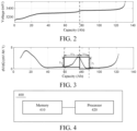
- the voltage knee point is one of multiple points with the fastest voltage change along with the capacity. The features of the voltage-capacity curve and the voltage knee point are described below with reference to FIG. 2 and FIG. 3 .
- FIG. 2 shows a voltage-capacity curve of a lithium ion battery.
- voltage platform areas There are three intervals where the voltage changes slowly with capacity in the voltage-capacity curve of lithium-ion battery, which are called voltage platform areas.
- the voltage knee point used for estimating the SOH of the battery is between the second voltage platform area and the third voltage platform area, which is the point with the fastest voltage change along with the capacity in the interval.
- the battery can be subjected to constant-current charge to reach the full-charge state after the electric quantity of the battery is emptied, and the initial capacity (recorded as Q new ) of the battery is recorded.
- the actual capacity of the battery is calculated according to the characteristics of the voltage knee point, and the calculation of the actual capacity of the battery according to the SOC is avoided, so that the problems that the estimation accuracy of the SOH is influenced by the error accumulation of the SOC and the precision of the SOC is influenced by the error of the SOH are avoided.
- the battery capacity in the voltage-capacity curve is calculated by a battery management system according to the SOC.
- the actual capacity of thee battery is calculated through the pre-calibrated reference capacity value corresponding to the voltage knee point in this embodiment of the present disclosure.
- the electric quantity of the battery is emptied, and then the battery is subjected to constant-current charging to reach the full-charge state.
- the voltage-capacity curve is recorded in the battery charging process.
- the reference capacity value corresponding to thee voltage knee point is determined through offline calibration by analyzing the characteristics of the voltage-capacity curve.
- the charging electric quantity between the voltage knee point and the full-charge state is calculated, the time for reaching the voltage knee point and the time for reaching the full-charge state can be recorded. Calculation is carried out according to the actual charging current and the time for charging the battery from the voltage knee point to the full-charge state. Because the reference capacity value corresponding to the voltage knee point is an accurate value, the charging electric quantity is also an accurate value, and the accurate actual capacity of the battery may be obtained by summing the reference capacity value and the charging electric quantity.
- the SOC absolute value is not involved in the process of estimating the actual capacity of the battery, so that the defect that the SOC estimation accuracy is excessively depended when the actual capacity of the battery is calculated in a traditional mode may be avoided.
- the battery does not need to be emptied, and the using habit of a common user is met. Experiments prove that the actual capacity of the battery can be accurately calculated when charging may be started with the SOC lower than 60%.
- the feature peak is identified according to the ratio of the perimeter to the area of each wave crest, and the voltage knee point determined according to the feature peak is the voltage knee point meeting the constant capacity characteristic.
- the multiple wave crests are identified in the voltage differential-capacity curve, and the first height and the first width between each wave crest and the adjacent wave trough on the left, and the second height and the second width between each wave crest and the adjacent wave trough on the right are calculated.
- the first height is a difference value of the voltage differential between each wave crest and the adjacent wave trough on the left
- the first width is a difference value of the capacity between each wave crest and the adjacent wave trough on the left
- the second height is an absolute value of the difference value of the voltage differential between each wave crest and the adjacent wave trough on the right
- the second width is an absolute value of the difference value of the capacity between each wave crest and the adjacent wave trough on the right.
- the determination index for each wave crest is calculated according to the first height, the first width, the second height, and the second width.
- a sum of the ratios of the perimeters to the areas of the left and right half-edge peaks of each wave crest is taken the determination index.
- the method further includes performing smoothing filtering on the voltage-capacity curve. After the voltage knee point is determined, the actual capacity of the battery can be estimated according to the mode described above.
- the voltage-capacity curve is detected and analyzed in real time in the battery charging process, the battery does not need to be subjected to deep discharge, the using habit of the user is met, and the method has great technical advantages and market value.
- the initial SOC of the battery does not need to be determined, the absolute value of the SOC is not involved, and the actual capacity of the battery can be calculated only by identifying the voltage knee point in the charging process, so that the estimation accuracy of the actual capacity of the battery is improved.
- the SOH of the battery can be obtained, and the estimation accuracy and speed of the SOH are improved.
- the voltage knee point is identified, automatic identification is realized by using the perimeter/area feature, and threshold setting does not need to be manually carried out according to different vehicle types and different aging degrees, so that the universality is improved.
- FIG. 4 is a schematic block diagram of a battery capacity estimation apparatus 400 according to an embodiment of the present disclosure.
- the battery capacity estimation apparatus 400 includes a memory 410, a processor 420, and a computer program stored in the memory 410 and operated with the processor 420.
- the processor 420 can implement the battery capacity estimation method as described above when executing the computer program.
- An embodiment of the present disclosure further provides a computer storage medium, a computer program is stored in the computer storage medium, and the computer program can be executed to implement the battery capacity estimation method according to this embodiment of the present disclosure.
- the battery capacity estimation apparatus 400 and the computer storage medium are configured to achieve the above mentioned battery capacity estimation method, and therefore the battery capacity estimation device and the computer storage medium also have similar advantages.
- the disclosed device and method may be implemented in other manners.
- the described device embodiment is merely an example.
- the unit division is merely a logical function division and may be other division during actual implementation.
- multiple units or components may be combined or integrated into another system, or some features may be ignored or not performed.
- All component embodiments of the present disclosure can be implemented through hardware, or software modules running on one or more processors, or a combination thereof. Those skilled in the art should understand that some or all of the functions of some modules according to embodiments of the present disclosure can be implemented in practice using the microprocessor or the DSP.
- the present disclosure can also be implemented as an apparatus program (e.g., a computer program and a computer program product) for executing a part or all of the methods described herein.
- Such a program implementing the present disclosure can be stored in the computer readable medium, or can be in a form of one or more signals. Such signals can be downloaded from an Internet website, or provided on a carrier signal, or provided in any other form.
Landscapes
- General Physics & Mathematics (AREA)
- Physics & Mathematics (AREA)
- Engineering & Computer Science (AREA)
- General Chemical & Material Sciences (AREA)
- Chemical Kinetics & Catalysis (AREA)
- Electrochemistry (AREA)
- Chemical & Material Sciences (AREA)
- Manufacturing & Machinery (AREA)
- Power Engineering (AREA)
- Charge And Discharge Circuits For Batteries Or The Like (AREA)
- Secondary Cells (AREA)
- Health & Medical Sciences (AREA)
- General Health & Medical Sciences (AREA)
- Medical Informatics (AREA)
- Tests Of Electric Status Of Batteries (AREA)
Abstract
Description
- The present disclosure claims priority to and benefits of
Chinese Patent Application No. 202111422355.6, entitled "BATTERY CAPACITY ESTIMATION METHOD AND APPARATUS, AND COMPUTER STORAGE MEDIUM" filed on November 26, 2021 - The present disclosure relates to the technical field of battery management, and more specifically to a battery capacity estimation method and apparatus, and a computer storage medium.
- The strong demand of people for new renewable energy solutions, such as electric vehicles, electric aircraft, and electric ships, has led to the rapid development of lithium-ion batteries. The batteries applied in the above systems will face more severe working conditions: higher power and energy demands, as well as greater temperature changes, all of which accelerate battery aging. Therefore, it is necessary to track the State Of Health (SOH) of the battery and determine when to terminate its lifespan. SOH is usually defined as the ratio between the actual capacity of the battery and the initial capacity of the battery within a given time.
- At present, when calculating the battery capacity, the main method is implemented by calculating the total electric quantity during the charging or discharging stage by fully charging and discharging the battery, or by charging and discharging within a certain State of Charge (SOC) range of the battery, and calculating the total battery capacity based on the charging or discharging electric quantity and the corresponding SOC range. The estimation accuracy in this method depends entirely on the accuracy of SOC. If there is a significant error in SOC estimation, it will affect the battery capacity estimation accuracy Especially for lithium iron phosphate batteries, the cumulative error of SOC will affect the accuracy of battery capacity. However, the error of the battery capacity can in turn affect the accuracy of SOC, leading to cross effects and ultimately rendering the estimation of battery capacity completely ineffective.
- If laboratory benchmarking methods are adopted, there are two drawbacks: 1: laboratory testing is very time-consuming, labor-intensive, and expensive, and cannot cover all working conditions; and 2: benchmarking against laboratory data in practical use would be too dogmatic and unable to estimate the actual battery capacity.
- The SUMMAR introduces a series of concepts in a simplified form that are further described in detail in the specific embodiments. The SUMMARY of the present disclosure is not intended to limit the key features and necessary technical features of the claimed technical solution, nor is it intended to determine the protection scope of the claimed technical solution.
- In order to solve the above technical problem, in a first aspect, an embodiment of the present disclosure provides a battery capacity estimation method, including: a voltage-capacity curve of a battery is acquired in real time in a battery charging process; differentiation is performed on the voltage-capacity curve to obtain a voltage differential-capacity curve; multiple wave crests are identified in the voltage differential-capacity curve; a first height and a first width between each wave crest and an adjacent wave trough on the left, and a second height and a second width between each wave crest and an adjacent wave trough on the right are calculated; a determination index is calculated according to the first height, the first width, the second height, and the second width, where p=2(h1+w1)/(h1·w1)+2(h2+w2)/(h2·w2), p represents the determination index, h1 represents the first height, w1 represents the first width, h2 represents the second height, and w2 represents the second width; a voltage knee point in the voltage-capacity curve is determined according to a wave crest with a minimum determination index; a pre-calibrated reference capacity value corresponding to the voltage knee point in the voltage-capacity curve is acquired; after the battery reaches a full-charge state, charging electric quantity of the battery from the voltage knee point to the full-charge state is acquired; and an actual capacity of the battery is obtained based on a sum of the reference capacity value and the charging electric quantity.
- According to the present disclosure, the capacity of the battery is estimated according to the voltage knee point on the voltage-capacity curve in the battery charging process, the estimation accuracy of the battery capacity may be improved, the battery does not need to be emptied, and the using habit of a user is met.
- In an embodiment, before the performing differentiation on the voltage-capacity curve, the method further includes performing smoothing filtering on the voltage-capacity curve.
- In an embodiment, the reference capacity value is calibrated by the following mode: the electric quantity of the battery is emptied, then constant-current charging is performed until reaching a full-charge state, the reference voltage-capacity curve of the battery in the constant-current charging process is recorded, and the reference capacity value is calibrated according to the voltage-capacity curve of the battery in the constant-current charging process.
- In an embodiment, the acquiring charging electric quantity of the battery from the voltage knee point to the full-charge state includes: time for charging the battery from the voltage knee point to the full-charge state is recorded; and the charging electric quantity is calculated according to the charging time and a charging current.
- In an embodiment, the method further includes: a state of health of the battery is estimated according to the actual capacity and a pre-calibrated initial capacity of the battery.
- In an embodiment, the battery is a lithium iron phosphate battery.
- In an embodiment, the initial capacity of the battery is determined by the following mode: the electric quantity of the battery is emptied and then constant-current charging is performed until reaching the full-charge state; and the initial capacity of the battery is recorded.
- In an embodiment, the estimating a state of health of the battery according to the actual capacity and a pre-calibrated initial capacity of the battery includes: SOH= Q/Qnew*100%, the actual capacity is represented with Q, the initial capacity is represented with Qnew, and the state of health of the battery is represented with SOH.
- In a second aspect, an embodiment of the present disclosure provides a battery capacity estimation apparatus, including a memory and a processor. A computer program operated with the processor is stored in the memory, and the computer program executes the battery capacity estimation method when being operated with the processor.
- In a third aspect, an embodiment of the present disclosure provides a computer storage medium. The computer program is stored in the computer storage medium. The computer program executes the abovementioned battery capacity estimation method when being executed.
- According to the battery capacity estimation method and apparatus provided by this embodiment of the present disclosure, the capacity of the battery is estimated according to the voltage knee point on the voltage-capacity curve in the battery charging process, and the absolute value of SOC is not involved. Therefore, the estimation accuracy of the battery capacity may be improved, the battery does not need to be emptied, and the using habit of the user is met.
- The above and other objects, features and advantages of the present disclosure will become more apparent through a more detailed description of the embodiments of the present disclosure in conjunction with the accompanying drawings. The accompanying drawings are used for providing further understanding of the embodiments of the present disclosure, and constitute a part of the description. They are used for explaining the present disclosure together with the embodiments of the present disclosure, and do not constitute a limitation of the present disclosure. In the accompanying drawings, same reference numerals generally represent same components or steps.
-
FIG. 1 is a schematic flowchart of a battery capacity estimation method according to an embodiment of the present disclosure; -
FIG. 2 is a schematic diagram of a voltage-capacity curve according to an embodiment of the present disclosure; -
FIG. 3 is a schematic diagram of a voltage differential-capacity curve according to an embodiment of the present disclosure; and -
FIG. 4 is a schematic block diagram of a battery capacity estimation apparatus according to an embodiment of the present disclosure. - In order to make the purpose, technical solution, and advantages of the present disclosure more obvious, the following will refer to the accompanying drawings to describe in detail the exemplary embodiments according to the present disclosure. Apparently, the described embodiments are merely some but not all of the embodiments of the present disclosure. It should be understood that, the present disclosure is not limited by the exemplary embodiments described herein. Based on the embodiments in the present disclosure, all the other embodiments obtained by those skilled in the art without making any creative work fall within the scope of protection of the present disclosure.
- In the following description, numerous specific details are given to facilitate a more thorough understanding of the present disclosure. However, it is obvious to those skilled in the art that the present disclosure can be implemented without one or more of these details. In other examples, to avoid confusion with the present disclosure, some technical features known in the art are not described.
- It is to be understood that the present disclosure can be implemented in different forms and should not be construed as being limited to the embodiments presented herein. Conversely, these embodiments are provided for the purpose of making the disclosure thorough and complete, and conveying the scope of the present disclosure fully to those skilled in the art.
- The terms are used herein merely for purpose of describing specific embodiments and not as a limitation of the present disclosure. When used herein, the singular forms "a", "an" and "the" are also meant to include the plural form, unless otherwise clearly indicated. It should also be understood that the terms "consisting of" and/or "including", when used in this specification, confirm the existence of the described features, integers, steps, operations, elements and/or components, but do not exclude the existence or addition of one or more other features, integers, steps, operations, elements, components and/or groups. As used herein, the term "and/or" includes any and all combinations of related listed items.
- For the purpose of thoroughly understanding the present disclosure, a detailed structure will be presented in the following description to explain the technical solution proposed in the present disclosure. Optional embodiments of the present disclosure are described in detail as follows. However, besides these detailed descriptions, the present disclosure may also have other implementations.
- A battery capacity estimation method and a battery capacity estimation apparatus provided in the embodiments of the present disclosure will be described below with reference to the accompanying drawings. Referring to
FIG. 1 first,FIG. 1 is a schematic flowchart of a battery capacity estimation method according to an embodiment of the present disclosure. As shown inFIG. 1 , the battery capacity estimation method includes: - S110: A voltage-capacity curve of a battery is acquired in real time in a battery charging process.
- S120: Differentiation is performed on the voltage-capacity curve to obtain a voltage differential-capacity curve.
- S130: Multiple wave crests are identified in the voltage differential-capacity curve.
- S140: A first height and a first width between each wave crest and an adjacent wave trough on the left, and a second height and a second width between each wave crest and an adjacent wave trough on the right are calculated.
- S150: A determination index is calculated according to the first height, the first width, the second height, and the second width, where p=2(h1+w1)/(h1·w1)+2(h2+w2)/(h2·w2), p represents the determination index, h1 represents the first height, w1 represents the first width, h2 represents the second height, and w2 represents the second width.
- S160: A voltage knee point in the voltage-capacity curve is determined according to a wave crest with a minimum determination index.
- S170: A pre-calibrated reference capacity value corresponding to the voltage knee point in the voltage-capacity curve is acquired.
- S180: After the battery reaches a full-charge state, charging electric quantity of the battery from the voltage knee point to the full-charge state is acquired.
- S190: An actual capacity of the battery is obtained based on a sum of the reference capacity value and the charging electric quantity
- According to the battery capacity estimation method in this embodiment of the present disclosure, the voltage-battery capacity curve is detected in real time in the battery charging process, curve characteristics are analyzed, the voltage knee point is identified, and then the actual capacity of the battery is estimated according to the voltage knee point. According to the method, the actual capacity of the battery is intelligently estimated according to the characteristic attributes of materials in the battery charging process, deep discharging does not need to be carried out on the battery, and the actual capacity of the battery may be accurately calculated under a condition that the initial SOC state of the battery is unknown. Moreover, the calculation process does not involve the absolute value of the SOC, so cross influence with the calculation of the SOC is avoided. According to the battery capacity estimation method in this embodiment of the present disclosure, the test cost of a laboratory can be greatly reduced, and the calculation efficiency and accuracy of the battery capacity may be remarkably improved. According to the present disclosure, the capacity of the battery is estimated according to the voltage knee point on the voltage-capacity curve in the battery charging process, the estimation accuracy of the battery capacity may be improved, the battery does not need to be emptied, and the using habit of the user is met.
- Specifically, in the battery charging process, the voltage-capacity curve of the battery is acquired in real time, and the voltage knee point is determined in the voltage-capacity curve. The battery includes a lithium ion battery, and specifically can be a lithium iron phosphate battery. The voltage knee point is one of multiple points with the fastest voltage change along with the capacity. The features of the voltage-capacity curve and the voltage knee point are described below with reference to
FIG. 2 and FIG. 3 . - Referring to
FIG. 2 first,FIG. 2 shows a voltage-capacity curve of a lithium ion battery. Generally, there are three intervals where the voltage changes slowly with capacity in the voltage-capacity curve of lithium-ion battery, which are called voltage platform areas. There is an area where the voltage changes fast along with the capacity between every two adjacent voltage platform areas, and the point with the fastest voltage change in the area is called the voltage knee point. According to this embodiment of the present disclosure, the voltage knee point used for estimating the SOH of the battery is between the second voltage platform area and the third voltage platform area, which is the point with the fastest voltage change along with the capacity in the interval. - Research shows that along with aging of the lithium ion battery, the capacity difference value between the battery capacity value corresponding to the voltage knee point and the battery capacity value corresponding to SOC=0 (namely the capacity value is 0) is kept unchanged. According to this embodiment of the present disclosure, the actual capacity of the battery is estimated according to this characteristic of the voltage knee point. After the actual capacity of the battery is estimated, the state of health (SOH) of the battery can be calculated according to the actual capacity of the battery, the SOH of the battery is the ratio of the actual capacity of the battery to the initial capacity of the battery, and the initial capacity of the battery can be obtained through calibration before delivery. Specifically, the battery can be subjected to constant-current charge to reach the full-charge state after the electric quantity of the battery is emptied, and the initial capacity (recorded as Qnew) of the battery is recorded. According to this embodiment of the present disclosure, the actual capacity of the battery is calculated according to the characteristics of the voltage knee point, and the calculation of the actual capacity of the battery according to the SOC is avoided, so that the problems that the estimation accuracy of the SOH is influenced by the error accumulation of the SOC and the precision of the SOC is influenced by the error of the SOH are avoided.
- Specifically, as mentioned above, as the battery capacity value corresponding to the voltage knee point remains unchanged, after the voltage knee point is identified according to the voltage-capacity curve in this embodiment of the present disclosure, the charging electric quantity (recorded as QHVP) of the battery in the interval from the voltage knee point to full-charge state of the battery is calculated, and the charging electric quantity and the capacity value (recorded as QHVTP) corresponding to the voltage knee point are summed, so that the actual capacity Q of the battery can be obtained, and Q=QHVP+QHVTP. The SOH of the battery is calculated according to the actual capacity Q of the battery and a pre-calibrated initial capacity Qnew, and SOH=Q/Qnew*100%.
- The battery capacity in the voltage-capacity curve is calculated by a battery management system according to the SOC. In order to avoid the introduction of SOC errors, the actual capacity of thee battery is calculated through the pre-calibrated reference capacity value corresponding to the voltage knee point in this embodiment of the present disclosure. Exemplarily, before the battery leaves a factory, the electric quantity of the battery is emptied, and then the battery is subjected to constant-current charging to reach the full-charge state. The voltage-capacity curve is recorded in the battery charging process. The reference capacity value corresponding to thee voltage knee point is determined through offline calibration by analyzing the characteristics of the voltage-capacity curve. When the charging electric quantity between the voltage knee point and the full-charge state is calculated, the time for reaching the voltage knee point and the time for reaching the full-charge state can be recorded. Calculation is carried out according to the actual charging current and the time for charging the battery from the voltage knee point to the full-charge state. Because the reference capacity value corresponding to the voltage knee point is an accurate value, the charging electric quantity is also an accurate value, and the accurate actual capacity of the battery may be obtained by summing the reference capacity value and the charging electric quantity.
- According to this embodiment of the present disclosure, the SOC absolute value is not involved in the process of estimating the actual capacity of the battery, so that the defect that the SOC estimation accuracy is excessively depended when the actual capacity of the battery is calculated in a traditional mode may be avoided. Moreover, according to this embodiment of the present disclosure, the battery does not need to be emptied, and the using habit of a common user is met. Experiments prove that the actual capacity of the battery can be accurately calculated when charging may be started with the SOC lower than 60%.
- Exemplarily, the voltage knee point is the point with the fastest voltage change along with the capacity, so that the voltage knee point can be determined according to the voltage differential-capacity curve, and the voltage knee point corresponds to the wave crest of the voltage differential-capacity curve. Specifically, the voltage-capacity curve is subjected to differentiation to obtain a voltage differential-capacity (dV/dQ-Q) curve, and the capacity value corresponding to the voltage knee point is determined according to the wave crest of the voltage differential-capacity curve.
- There are multiple wave crests generally in the voltage differential-capacity curve. In order to determine the voltage knee point, it is needed to determine a feature peak in the voltage differential-capacity curve, namely the wave crest corresponding to the voltage knee point. According to this embodiment of the present disclosure, the feature peak is identified according to the ratio of the perimeter to the area of each wave crest, and the voltage knee point determined according to the feature peak is the voltage knee point meeting the constant capacity characteristic.
- Specifically, referring to
FIG. 3 , the multiple wave crests are identified in the voltage differential-capacity curve, and the first height and the first width between each wave crest and the adjacent wave trough on the left, and the second height and the second width between each wave crest and the adjacent wave trough on the right are calculated. The first height is a difference value of the voltage differential between each wave crest and the adjacent wave trough on the left, and the first width is a difference value of the capacity between each wave crest and the adjacent wave trough on the left. The second height is an absolute value of the difference value of the voltage differential between each wave crest and the adjacent wave trough on the right, and the second width is an absolute value of the difference value of the capacity between each wave crest and the adjacent wave trough on the right. - Then, the determination index for each wave crest is calculated according to the first height, the first width, the second height, and the second width. A sum of the ratios of the perimeters to the areas of the left and right half-edge peaks of each wave crest is taken the determination index. Specifically, the determination index is shown as p=2(h1+w1)/(h1·w1)+2(h2+w2)/(h2·w2), h1 represents the first height, w1 represents the first width, h2 represents the second height, and w2 represents the second width. After the determination index is calculated for each wave crest, a wave crest with a minimum determination index is used as the feature peak and is used for determining the voltage knee point.
- In some embodiments, in order to reduce the errors, before the voltage-capacity curve is subjected to differentiation, the method further includes performing smoothing filtering on the voltage-capacity curve. After the voltage knee point is determined, the actual capacity of the battery can be estimated according to the mode described above.
- According to this embodiment of the present disclosure, the voltage-capacity curve is detected and analyzed in real time in the battery charging process, the battery does not need to be subjected to deep discharge, the using habit of the user is met, and the method has great technical advantages and market value. In the calculation process, the initial SOC of the battery does not need to be determined, the absolute value of the SOC is not involved, and the actual capacity of the battery can be calculated only by identifying the voltage knee point in the charging process, so that the estimation accuracy of the actual capacity of the battery is improved. Further, the SOH of the battery can be obtained, and the estimation accuracy and speed of the SOH are improved. Moreover, when the voltage knee point is identified, automatic identification is realized by using the perimeter/area feature, and threshold setting does not need to be manually carried out according to different vehicle types and different aging degrees, so that the universality is improved.
- An embodiment of the present disclosure further provides a battery capacity estimation apparatus. The apparatus can be configured to implement the abovementioned battery capacity estimation method. Referring to
FIG. 4, FIG. 4 is a schematic block diagram of a batterycapacity estimation apparatus 400 according to an embodiment of the present disclosure. - As shown in
FIG. 4 , the batterycapacity estimation apparatus 400 includes amemory 410, aprocessor 420, and a computer program stored in thememory 410 and operated with theprocessor 420. Theprocessor 420 can implement the battery capacity estimation method as described above when executing the computer program. Theprocessor 420 can be implemented by software, hardware, firmware or a combination thereof, and can utilize at least one of a circuit, a single or multiple Application Specific Integrated Circuits (ASIC), a Digital Signal Processor (DSP), a Digital Signal Processing Device (DSPD), a Programmable Logic Device (PLD), a Field Programmable Gate Array (FPGA), a Central Processing Unit (CPU), a controller, a microcontroller, and a microprocessor, so that the apparatus can execute part or all of the steps or any combination of the steps of the battery capacity estimation method in each embodiment of the present disclosure. - An embodiment of the present disclosure further provides a computer storage medium, a computer program is stored in the computer storage medium, and the computer program can be executed to implement the battery capacity estimation method according to this embodiment of the present disclosure.
- According to this embodiment of the present disclosure, the battery
capacity estimation apparatus 400 and the computer storage medium are configured to achieve the above mentioned battery capacity estimation method, and therefore the battery capacity estimation device and the computer storage medium also have similar advantages. - Although exemplary embodiments have been described with reference to accompanying drawings, it should be understood that the above exemplary embodiments are only illustrative, and not intended to limit the scope of the present disclosure thereto. Various changes and modifications can be made by a person of ordinary skill in the art without departing from the scope and spirit of the present disclosure. All these changes and modifications are intended to be embraced in the scope of the present disclosure as defined in the appended claims.
- A person of ordinary skill in the art may notice that the exemplary units and algorithm steps described with reference to the embodiments disclosed in this specification can be implemented in electronic hardware, or a combination of computer software and electronic hardware. Whether the functions are executed in a mode of hardware or software depends on particular applications and design constraint conditions of the technical solutions. A person skilled in the art can use different methods to implement the described functions for each particular application, but it should not be considered that the implementation goes beyond the scope of the embodiments of the present disclosure.
- In the several embodiments provided in the present disclosure, it should be understood that the disclosed device and method may be implemented in other manners. For example, the described device embodiment is merely an example. For example, the unit division is merely a logical function division and may be other division during actual implementation. For example, multiple units or components may be combined or integrated into another system, or some features may be ignored or not performed.
- Numerous specific details are set forth in the specification provided herein. However, it can be understood that, the embodiments of the present disclosure may be practiced without the specific details. In some examples, known methods, structures, and technologies are not disclosed in detail, so as not to mix up understanding on the specification.
- Similarly, it should be understood that to simplify the present disclosure and help to understand one or more of disclosure aspects, in the descriptions of the exemplary embodiments of the present disclosure, features of the present disclosure are sometimes grouped into a single embodiment or figure, or descriptions thereof. However, the method of the present disclosure should not be interpreted as reflecting the following intent: The present disclosure requires more features to be protected than those explicitly stated in each claim. More definitely, as reflected in the corresponding claims, the inventiveness of the disclosure lies in resolving the corresponding technical problem using features less than all features of a single embodiment disclosed above. Therefore, the claims following the specific implementation are hereby expressly incorporated into the specific implementation, with each claim standing on its own as a separate embodiment of the present disclosure.
- A person skilled in the art may understand that, all features disclosed in this specification (including the accompanying claims, abstract and drawings), and all processes or units of any method or device disclosed herein may be combined in any combination, unless features are mutually exclusive. Unless otherwise explicitly stated, each feature disclosed in this specification (including the accompanying claims, abstract and drawings) may be replaced with an alternative feature serving the same, equivalent or similar purpose.
- In addition, a person skilled in the art can understand that, although some embodiments herein include some but not other features included in other embodiments, combinations of features of different embodiments are meant to be within the scope of the present disclosure and to form different embodiments. For example, in the claims, any one of the claimed embodiments may be used in any combination.
- All component embodiments of the present disclosure can be implemented through hardware, or software modules running on one or more processors, or a combination thereof. Those skilled in the art should understand that some or all of the functions of some modules according to embodiments of the present disclosure can be implemented in practice using the microprocessor or the DSP. The present disclosure can also be implemented as an apparatus program (e.g., a computer program and a computer program product) for executing a part or all of the methods described herein. Such a program implementing the present disclosure can be stored in the computer readable medium, or can be in a form of one or more signals. Such signals can be downloaded from an Internet website, or provided on a carrier signal, or provided in any other form.
- It is be noted that the above-mentioned embodiments illustrate rather than limit the present disclosure, and those skilled in the art may devise alternative embodiments without departing from the scope of the appended claims. In the claims, any reference signs placed between parentheses shall not be construed as limiting the claims. The present disclosure can be implemented by way of hardware including several different elements and an appropriately programmed computer. In the unit claims enumerating several apparatuses, several of these apparatuses can be specifically embodied by the same item of hardware. The use of the words such as "first", "second", "third", and the like does not denote any order. These words can be interpreted as names.
- The foregoing descriptions are merely a specific implementation of the present disclosure, but are not intended to limit the protection scope of the present disclosure. Any variation or replacement readily figured out by those skilled in the art within the technical scope disclosed in the present disclosure shall fall within the protection scope of the present disclosure. Therefore, the protection scope of the present disclosure shall be subject to the protection scope of the claims.
Claims (20)
- A battery capacity estimation method, comprising:S110: acquiring a voltage-capacity curve of a battery in real time in a battery charging process;S 120: performing differentiation on the voltage-capacity curve to obtain a voltage differential-capacity curve;S130: identifying a plurality of wave crests in the voltage differential-capacity curve;S140: calculating a first height and a first width between each wave crest and an adjacent wave trough on the left, and a second height and a second width between each wave crest and an adjacent wave trough on the right;S150: calculating a determination index according to the first height, the first width, the second height, and the second width, wherein p=2(h1+w1)(h1·w1)+2(h2+w2)/(h2·w2), p represents the determination index, h1 represents the first height, w1 represents the first width, h2 represents the second height, and w2 represents the second width;S160: determining a voltage knee point in the voltage-capacity curve according to a wave crest with a minimum determination index;S170: acquiring a pre-calibrated reference capacity value corresponding to the voltage knee point in the voltage-capacity curve;S180: after the battery reaches a full-charge state, acquiring charging electric quantity of the battery from the voltage knee point to the full-charge state; andS190: obtaining an actual capacity of the battery based on a sum of the reference capacity value and the charging electric quantity.
- The battery capacity estimation method according to claim 1, before the performing differentiation on the voltage-capacity curve, the method further comprising performing smoothing filtering on the voltage-capacity curve.
- The battery capacity estimation method according to any one of claims 1 to 2, wherein the reference capacity value is calibrated by the following mode:
emptying the electric quantity of the battery, then performing constant-current charging until reaching the full-charge state, recording the voltage-capacity curve of the battery in the constant-current charging process, and calibrating the reference capacity value according to the voltage-capacity curve of the battery in the constant-current charging process. - The battery capacity estimation method according to any one of claims 1 to 3, wherein the acquiring charging electric quantity of the battery from the voltage knee point to the full-charge state comprises:recording time for charging the battery from the voltage knee point to the full-charge state; andcalculating the charging electric quantity according to the charging time and a charging current.
- The battery capacity estimation method according to any one of claims 1 to 4, further comprising:
estimating a state of health of the battery according to the actual capacity and a pre-calibrated initial capacity of the battery. - The battery capacity estimation method according to any one of claims 1 to 5, wherein the battery is a lithium iron phosphate battery.
- The battery capacity estimation method according to claim 5, wherein the initial capacity of the battery is determined by the following mode:emptying the electric quantity of the battery and then performing constant-current charging until reaching the full-charge state; andrecording the initial capacity of the battery.
- The battery capacity estimation method according to any one of claims 5 to 7, wherein the estimating a state of health of the battery according to the actual capacity and a pre-calibrated initial capacity of the battery comprises:
SOH= Q/Qnew*100%, wherein the actual capacity is represented with Q, the initial capacity is represented with Qnew, and the state of health of the battery is represented with SOH. - A battery capacity estimation apparatus (400), comprising a memory (410) and a processor (420), a computer program operated with the processor (420) being stored in the memory (410), and the computer program executing the following steps when being operated with the processor (420):acquiring a voltage-capacity curve of a battery in real time in a battery charging process;performing differentiation on the voltage-capacity curve to obtain a voltage differential-capacity curve;identifying a plurality of wave crests in the voltage differential-capacity curve;calculating a first height and a first width between each wave crest and an adjacent wave trough on the left, and a second height and a second width between each wave crest and an adjacent wave trough on the right;calculating a determination index according to the first height, the first width, the second height, and the second width, wherein p=2(h1+w1)/(h1·w1)+2(h2+w2)/(h2·w2), p represents the determination index, h1 represents the first height, w1 represents the first width, h2 represents the second height, and w2 represents the second width;determining a voltage knee point in the voltage-capacity curve according to a wave crest with a minimum determination index;acquiring a pre-calibrated reference capacity value corresponding to the voltage knee point in the voltage-capacity curve;after the battery reaches a full-charge state, acquiring charging electric quantity of the battery from the voltage knee point to the full-charge state; andobtaining an actual capacity of the battery based on a sum of the reference capacity value and the charging electric quantity.
- The battery capacity estimation apparatus (400) according to claim 9, wherein before the performing differentiation on the voltage-capacity curve, the computer program further executes: performing smoothing filtering on the voltage-capacity curve.
- The battery capacity estimation apparatus (400) according to any one of claims 9 to 10, wherein the reference capacity value is calibrated by the following mode:
emptying the electric quantity of the battery, then performing constant-current charging until reaching the full-charge state, recording the voltage-capacity curve of the battery in the constant-current charging process, and calibrating the reference capacity value according to the voltage-capacity curve of the battery in the constant-current charging process. - The battery capacity estimation apparatus (400) according to any one of claims 9 to 11, wherein the acquiring charging electric quantity of the battery from the voltage knee point to the full-charge state comprises:recording time for charging the battery from the voltage knee point to the full-charge state; andcalculating the charging electric quantity according to the charging time and a charging current.
- The battery capacity estimation apparatus (400) according to any one of claims 9 to 12, wherein the computer program further executes:
estimating a state of health of the battery according to the actual capacity and a pre-calibrated initial capacity of the battery. - The battery capacity estimation apparatus (400) according to claim 9 to 13, wherein the battery is a lithium iron phosphate battery.
- A computer storage medium, storing a computer program, wherein the computer program implements the following steps when being executed:acquiring a voltage-capacity curve of a battery in real time in a battery charging process;performing differentiation on the voltage-capacity curve to obtain a voltage differential-capacity curve;identifying a plurality of wave crests in the voltage differential-capacity curve;calculating a first height and a first width between each wave crest and an adjacent wave trough on the left, and a second height and a second width between each wave crest and an adjacent wave trough on the right;calculating a determination index according to the first height, the first width, the second height, and the second width, wherein p=2(h1+w1)/(h1·w1)+2(h2+w2)/(h2·w2), p represents the determination index, h1 represents the first height, w1 represents the first width, h2 represents the second height, and w2 represents the second width;determining a voltage knee point in the voltage-capacity curve according to a wave crest with a minimum determination index;acquiring a pre-calibrated reference capacity value corresponding to the voltage knee point in the voltage-capacity curve;after the battery reaches a full-charge state, acquiring charging electric quantity of the battery from the voltage knee point to the full-charge state; andobtaining an actual capacity of the battery based on a sum of the reference capacity value and the charging electric quantity.
- The computer storage medium according to claim 15, wherein before the performing differentiation on the voltage-capacity curve, the computer program further implements: performing smoothing filtering on the voltage-capacity curve.
- The computer storage medium according to any one of claims 15 to 16, wherein the reference capacity value is calibrated by the following mode:
emptying the electric quantity of the battery, then performing constant-current charging until reaching the full-charge state, recording the voltage-capacity curve of the battery in the constant-current charging process, and calibrating the reference capacity value according to the voltage-capacity curve of the battery in the constant-current charging process. - The computer storage medium according to any one of claims 15 to 17, wherein the acquiring charging electric quantity of the battery from the voltage knee point to the full-charge state comprises:recording time for charging the battery from the voltage knee point to the full-charge state; andcalculating the charging electric quantity according to the charging time and a charging current.
- The computer storage medium according to any one of claims 15 to 18, wherein the computer program further implements:
estimating a state of health of the battery according to the actual capacity and a pre-calibrated initial capacity of the battery. - The computer storage medium according to claim 15 to 19, wherein the battery is a lithium iron phosphate battery.
Applications Claiming Priority (2)
| Application Number | Priority Date | Filing Date | Title |
|---|---|---|---|
| CN202111422355.6A CN116184222B (en) | 2021-11-26 | 2021-11-26 | Method, apparatus and computer storage medium for estimating battery capacity |
| PCT/CN2022/118754 WO2023093225A1 (en) | 2021-11-26 | 2022-09-14 | Battery capacity estimation method and apparatus, and computer storage medium |
Publications (3)
| Publication Number | Publication Date |
|---|---|
| EP4390419A1 true EP4390419A1 (en) | 2024-06-26 |
| EP4390419A4 EP4390419A4 (en) | 2024-12-25 |
| EP4390419B1 EP4390419B1 (en) | 2025-10-29 |
Family
ID=86444804
Family Applications (1)
| Application Number | Title | Priority Date | Filing Date |
|---|---|---|---|
| EP22897312.9A Active EP4390419B1 (en) | 2021-11-26 | 2022-09-14 | Battery capacity estimation method and apparatus, and computer storage medium |
Country Status (13)
| Country | Link |
|---|---|
| US (1) | US12578393B2 (en) |
| EP (1) | EP4390419B1 (en) |
| JP (1) | JP7738168B2 (en) |
| KR (1) | KR102925653B1 (en) |
| CN (1) | CN116184222B (en) |
| AU (1) | AU2022397745B2 (en) |
| CA (1) | CA3232287A1 (en) |
| CL (1) | CL2024001154A1 (en) |
| ES (1) | ES3054284T3 (en) |
| IL (1) | IL311584A (en) |
| MX (1) | MX2024004339A (en) |
| PL (1) | PL4390419T3 (en) |
| WO (1) | WO2023093225A1 (en) |
Families Citing this family (5)
| Publication number | Priority date | Publication date | Assignee | Title |
|---|---|---|---|---|
| CN116430242B (en) * | 2023-05-31 | 2025-07-11 | 深蓝汽车科技有限公司 | Battery cell capacity estimation method, device, server and storage medium |
| CN119846493A (en) * | 2023-12-15 | 2025-04-18 | 重庆弗迪电池研究院有限公司 | Method for determining battery capacity and method for determining battery health status |
| CN119881686A (en) * | 2024-12-12 | 2025-04-25 | 比亚迪股份有限公司 | Calibration method, calibration device, computer device, electronic equipment, medium and product |
| CN120199928B (en) * | 2025-05-23 | 2025-09-16 | 比亚迪股份有限公司 | Voltage inflection point determination method, equalization method, device, equipment and medium |
| CN121142348B (en) * | 2025-11-19 | 2026-04-21 | 宁德时代新能源科技股份有限公司 | Battery capacity calculation method, OCV curve correction device, medium and product |
Family Cites Families (24)
| Publication number | Priority date | Publication date | Assignee | Title |
|---|---|---|---|---|
| JPH06342044A (en) * | 1993-05-31 | 1994-12-13 | Omron Corp | Battery measuring apparatus |
| CN100517930C (en) * | 2005-03-15 | 2009-07-22 | 三菱电机株式会社 | Converter |
| JP4561859B2 (en) * | 2008-04-01 | 2010-10-13 | トヨタ自動車株式会社 | Secondary battery system |
| JP5282789B2 (en) * | 2011-01-11 | 2013-09-04 | 株式会社デンソー | Battery capacity detection device for lithium ion secondary battery |
| EP2610629B1 (en) * | 2011-12-29 | 2015-06-10 | BlackBerry Limited | Power pack remaining capacity level detection |
| JP5940145B2 (en) | 2012-04-20 | 2016-06-29 | 日立オートモティブシステムズ株式会社 | Secondary battery system, secondary battery deterioration state judgment method |
| JP2013247003A (en) * | 2012-05-28 | 2013-12-09 | Sony Corp | Charge control device for secondary battery, charge control method for secondary battery, charged state estimation device for secondary battery, charged state estimation method for secondary battery, deterioration degree estimation device for secondary battery, deterioration degree estimation method for secondary battery, and secondary battery device |
| KR102080632B1 (en) * | 2013-10-28 | 2020-04-14 | 현대모비스 주식회사 | Battery management system and its operating method |
| CN104931882B (en) * | 2014-03-21 | 2018-04-20 | 比亚迪股份有限公司 | The method and apparatus of power battery cubage correction |
| CN108226783B (en) | 2016-12-21 | 2019-12-10 | 比亚迪股份有限公司 | SOC estimation method and SOC estimation device, and electric vehicle |
| JP2019056595A (en) * | 2017-09-20 | 2019-04-11 | 三菱自動車工業株式会社 | Secondary battery system |
| JP6301048B1 (en) | 2017-10-05 | 2018-03-28 | 三菱電機株式会社 | Battery management device and battery pack system |
| KR102206606B1 (en) * | 2017-11-16 | 2021-01-21 | 주식회사 엘지화학 | Apparatus for estimating remain capacity |
| KR101930646B1 (en) * | 2017-11-22 | 2019-03-11 | 주식회사 포스코아이씨티 | Apparatus and Method for Estimating Capacity of Battery Using Second Order Differential Voltage Curve |
| CN108008183B (en) | 2017-11-28 | 2021-01-15 | 深圳市路畅科技股份有限公司 | Electric quantity measuring method, system, equipment and computer storage medium |
| CN110320477B (en) | 2018-03-30 | 2021-09-03 | 比亚迪股份有限公司 | SOC (State of Charge) calculation method and device of power battery pack and electric automobile |
| CN110549909B (en) * | 2018-03-30 | 2021-06-18 | 比亚迪股份有限公司 | SOH calculation method, device and electric vehicle of power battery pack |
| WO2020026058A1 (en) * | 2018-07-31 | 2020-02-06 | 株式会社半導体エネルギー研究所 | Power storage system and method for operating power storage system |
| KR102677986B1 (en) * | 2018-12-21 | 2024-06-21 | 주식회사 엘지에너지솔루션 | Apparatus and method for diagnosing battery |
| KR20200093228A (en) * | 2019-01-28 | 2020-08-05 | 세방전지(주) | Apparatus and method for calculating the state of charge of a lfp battery |
| KR102768486B1 (en) * | 2019-02-22 | 2025-02-19 | 주식회사 엘지에너지솔루션 | Apparatus and method for estimating state of battery |
| CN112578296B (en) * | 2019-09-27 | 2022-03-15 | 比亚迪股份有限公司 | Battery capacity estimation method and device and computer storage medium |
| JP2021150076A (en) | 2020-03-17 | 2021-09-27 | 株式会社豊田自動織機 | Power storage device |
| CN111551868B (en) * | 2020-05-08 | 2022-04-12 | 浙江吉利控股集团有限公司 | A Consistency Analysis Method of LiFePO4 Battery System |
-
2021
- 2021-11-26 CN CN202111422355.6A patent/CN116184222B/en active Active
-
2022
- 2022-09-14 PL PL22897312.9T patent/PL4390419T3/en unknown
- 2022-09-14 CA CA3232287A patent/CA3232287A1/en active Pending
- 2022-09-14 AU AU2022397745A patent/AU2022397745B2/en active Active
- 2022-09-14 JP JP2024510620A patent/JP7738168B2/en active Active
- 2022-09-14 IL IL311584A patent/IL311584A/en unknown
- 2022-09-14 MX MX2024004339A patent/MX2024004339A/en unknown
- 2022-09-14 ES ES22897312T patent/ES3054284T3/en active Active
- 2022-09-14 EP EP22897312.9A patent/EP4390419B1/en active Active
- 2022-09-14 WO PCT/CN2022/118754 patent/WO2023093225A1/en not_active Ceased
- 2022-09-14 KR KR1020247008537A patent/KR102925653B1/en active Active
-
2024
- 2024-03-20 US US18/610,753 patent/US12578393B2/en active Active
- 2024-04-12 CL CL2024001154A patent/CL2024001154A1/en unknown
Also Published As
| Publication number | Publication date |
|---|---|
| MX2024004339A (en) | 2024-04-24 |
| IL311584A (en) | 2024-05-01 |
| PL4390419T3 (en) | 2026-03-23 |
| CL2024001154A1 (en) | 2024-08-16 |
| JP7738168B2 (en) | 2025-09-11 |
| AU2022397745B2 (en) | 2025-10-02 |
| KR102925653B1 (en) | 2026-02-11 |
| JP2024541168A (en) | 2024-11-08 |
| KR20240049310A (en) | 2024-04-16 |
| AU2022397745A1 (en) | 2024-04-04 |
| WO2023093225A1 (en) | 2023-06-01 |
| US12578393B2 (en) | 2026-03-17 |
| CA3232287A1 (en) | 2023-06-01 |
| EP4390419A4 (en) | 2024-12-25 |
| CN116184222B (en) | 2025-01-14 |
| ES3054284T3 (en) | 2026-02-02 |
| US20240230771A1 (en) | 2024-07-11 |
| CN116184222A (en) | 2023-05-30 |
| EP4390419B1 (en) | 2025-10-29 |
Similar Documents
| Publication | Publication Date | Title |
|---|---|---|
| EP4390419A1 (en) | Battery capacity estimation method and apparatus, and computer storage medium | |
| CN108828461B (en) | Power battery SOH value estimation method and system | |
| CN110988690B (en) | Battery state of health correction method, device, management system and storage medium | |
| JP6844683B2 (en) | Power storage element management device, SOC reset method, power storage element module, power storage element management program and mobile | |
| CN107402353B (en) | Method and system for carrying out filtering estimation on state of charge of lithium ion battery | |
| CN106249171B (en) | A kind of electrokinetic cell system identification and method for estimating state for the wide sampling interval | |
| EP1688754B1 (en) | Battery management apparatus | |
| CN107167743B (en) | Electric vehicle-based state of charge estimation method and device | |
| CN112986842B (en) | Method, device and device for estimating battery state of charge | |
| JP6509725B2 (en) | Estimating the state of charge of the battery | |
| CN105021996A (en) | Battery SOH (section of health) estimation method of energy storage power station BMS (battery management system) | |
| CN112858924A (en) | Method and device for estimating residual energy of power battery, vehicle and storage medium | |
| CN113447821A (en) | Method for estimating state of charge of battery | |
| CN108931732A (en) | Method for estimating the electric current and state-of-charge of battery pack or battery unit | |
| CN109061482B (en) | Battery health degree prediction method and device | |
| CN114778946B (en) | A battery impedance measurement method, device, equipment and medium | |
| CN115219918A (en) | A Lithium-ion Battery Life Prediction Method Based on Capacity Decay Combination Model | |
| CN115236527A (en) | Electronic circuit for determining the state of charge of a battery cell | |
| CN113296010A (en) | Battery health state online evaluation method based on differential voltage analysis | |
| CN112394290B (en) | Battery pack SOH estimation method, device, computer equipment and storage medium | |
| CN108519557B (en) | A kind of power battery parameter identification method suitable for sparse data | |
| CN117277459A (en) | Battery charging control method and device | |
| CN115389945B (en) | Determination method and device for SOH of retired battery, electronic equipment and storage medium | |
| CN114578229A (en) | Power battery state of health determination method, device and readable storage medium | |
| CN121899683A (en) | Battery health state estimation method, device, equipment and storage medium |
Legal Events
| Date | Code | Title | Description |
|---|---|---|---|
| STAA | Information on the status of an ep patent application or granted ep patent |
Free format text: STATUS: THE INTERNATIONAL PUBLICATION HAS BEEN MADE |
|
| PUAI | Public reference made under article 153(3) epc to a published international application that has entered the european phase |
Free format text: ORIGINAL CODE: 0009012 |
|
| STAA | Information on the status of an ep patent application or granted ep patent |
Free format text: STATUS: REQUEST FOR EXAMINATION WAS MADE |
|
| 17P | Request for examination filed |
Effective date: 20240318 |
|
| AK | Designated contracting states |
Kind code of ref document: A1 Designated state(s): AL AT BE BG CH CY CZ DE DK EE ES FI FR GB GR HR HU IE IS IT LI LT LU LV MC MK MT NL NO PL PT RO RS SE SI SK SM TR |
|
| A4 | Supplementary search report drawn up and despatched |
Effective date: 20241125 |
|
| RIC1 | Information provided on ipc code assigned before grant |
Ipc: G01R 31/396 20190101ALI20241119BHEP Ipc: G01R 31/388 20190101AFI20241119BHEP |
|
| DAV | Request for validation of the european patent (deleted) | ||
| DAX | Request for extension of the european patent (deleted) | ||
| GRAP | Despatch of communication of intention to grant a patent |
Free format text: ORIGINAL CODE: EPIDOSNIGR1 |
|
| STAA | Information on the status of an ep patent application or granted ep patent |
Free format text: STATUS: GRANT OF PATENT IS INTENDED |
|
| RIC1 | Information provided on ipc code assigned before grant |
Ipc: H01M 10/052 20100101ALI20250516BHEP Ipc: G01R 31/388 20190101AFI20250516BHEP |
|
| INTG | Intention to grant announced |
Effective date: 20250528 |
|
| GRAS | Grant fee paid |
Free format text: ORIGINAL CODE: EPIDOSNIGR3 |
|
| P01 | Opt-out of the competence of the unified patent court (upc) registered |
Free format text: CASE NUMBER: UPC_APP_2195_4390419/2025 Effective date: 20250801 |
|
| GRAA | (expected) grant |
Free format text: ORIGINAL CODE: 0009210 |
|
| STAA | Information on the status of an ep patent application or granted ep patent |
Free format text: STATUS: THE PATENT HAS BEEN GRANTED |
|
| AK | Designated contracting states |
Kind code of ref document: B1 Designated state(s): AL AT BE BG CH CY CZ DE DK EE ES FI FR GB GR HR HU IE IS IT LI LT LU LV MC MK MT NL NO PL PT RO RS SE SI SK SM TR |
|
| REG | Reference to a national code |
Ref country code: CH Ref legal event code: F10 Free format text: ST27 STATUS EVENT CODE: U-0-0-F10-F00 (AS PROVIDED BY THE NATIONAL OFFICE) Effective date: 20251029 Ref country code: GB Ref legal event code: FG4D |
|
| REG | Reference to a national code |
Ref country code: NL Ref legal event code: FP |
|
| REG | Reference to a national code |
Ref country code: DE Ref legal event code: R096 Ref document number: 602022024200 Country of ref document: DE |
|
| REG | Reference to a national code |
Ref country code: IE Ref legal event code: FG4D |
|
| REG | Reference to a national code |
Ref country code: ES Ref legal event code: FG2A Ref document number: 3054284 Country of ref document: ES Kind code of ref document: T3 Effective date: 20260202 |
|
| REG | Reference to a national code |
Ref country code: LT Ref legal event code: MG9D |
|
| PG25 | Lapsed in a contracting state [announced via postgrant information from national office to epo] |
Ref country code: NO Free format text: LAPSE BECAUSE OF FAILURE TO SUBMIT A TRANSLATION OF THE DESCRIPTION OR TO PAY THE FEE WITHIN THE PRESCRIBED TIME-LIMIT Effective date: 20260129 |
|
| PG25 | Lapsed in a contracting state [announced via postgrant information from national office to epo] |
Ref country code: FI Free format text: LAPSE BECAUSE OF FAILURE TO SUBMIT A TRANSLATION OF THE DESCRIPTION OR TO PAY THE FEE WITHIN THE PRESCRIBED TIME-LIMIT Effective date: 20251029 Ref country code: HR Free format text: LAPSE BECAUSE OF FAILURE TO SUBMIT A TRANSLATION OF THE DESCRIPTION OR TO PAY THE FEE WITHIN THE PRESCRIBED TIME-LIMIT Effective date: 20251029 |
|
| PG25 | Lapsed in a contracting state [announced via postgrant information from national office to epo] |
Ref country code: RS Free format text: LAPSE BECAUSE OF FAILURE TO SUBMIT A TRANSLATION OF THE DESCRIPTION OR TO PAY THE FEE WITHIN THE PRESCRIBED TIME-LIMIT Effective date: 20260129 |
|
| PG25 | Lapsed in a contracting state [announced via postgrant information from national office to epo] |
Ref country code: IS Free format text: LAPSE BECAUSE OF FAILURE TO SUBMIT A TRANSLATION OF THE DESCRIPTION OR TO PAY THE FEE WITHIN THE PRESCRIBED TIME-LIMIT Effective date: 20260228 |
|
| PG25 | Lapsed in a contracting state [announced via postgrant information from national office to epo] |
Ref country code: PT Free format text: LAPSE BECAUSE OF FAILURE TO SUBMIT A TRANSLATION OF THE DESCRIPTION OR TO PAY THE FEE WITHIN THE PRESCRIBED TIME-LIMIT Effective date: 20260302 |
|
| PG25 | Lapsed in a contracting state [announced via postgrant information from national office to epo] |
Ref country code: LV Free format text: LAPSE BECAUSE OF FAILURE TO SUBMIT A TRANSLATION OF THE DESCRIPTION OR TO PAY THE FEE WITHIN THE PRESCRIBED TIME-LIMIT Effective date: 20251029 |