EP4390203A1 - Air brake tube - Google Patents
Air brake tube Download PDFInfo
- Publication number
- EP4390203A1 EP4390203A1 EP22858189.8A EP22858189A EP4390203A1 EP 4390203 A1 EP4390203 A1 EP 4390203A1 EP 22858189 A EP22858189 A EP 22858189A EP 4390203 A1 EP4390203 A1 EP 4390203A1
- Authority
- EP
- European Patent Office
- Prior art keywords
- polyamide
- layer
- inner layer
- plasticized
- unplasticized
- Prior art date
- Legal status (The legal status is an assumption and is not a legal conclusion. Google has not performed a legal analysis and makes no representation as to the accuracy of the status listed.)
- Pending
Links
Images

Classifications
-
- F—MECHANICAL ENGINEERING; LIGHTING; HEATING; WEAPONS; BLASTING
- F16—ENGINEERING ELEMENTS AND UNITS; GENERAL MEASURES FOR PRODUCING AND MAINTAINING EFFECTIVE FUNCTIONING OF MACHINES OR INSTALLATIONS; THERMAL INSULATION IN GENERAL
- F16L—PIPES; JOINTS OR FITTINGS FOR PIPES; SUPPORTS FOR PIPES, CABLES OR PROTECTIVE TUBING; MEANS FOR THERMAL INSULATION IN GENERAL
- F16L9/00—Rigid pipes
- F16L9/12—Rigid pipes of plastics with or without reinforcement
- F16L9/133—Rigid pipes of plastics with or without reinforcement the walls consisting of two layers
-
- F—MECHANICAL ENGINEERING; LIGHTING; HEATING; WEAPONS; BLASTING
- F16—ENGINEERING ELEMENTS AND UNITS; GENERAL MEASURES FOR PRODUCING AND MAINTAINING EFFECTIVE FUNCTIONING OF MACHINES OR INSTALLATIONS; THERMAL INSULATION IN GENERAL
- F16L—PIPES; JOINTS OR FITTINGS FOR PIPES; SUPPORTS FOR PIPES, CABLES OR PROTECTIVE TUBING; MEANS FOR THERMAL INSULATION IN GENERAL
- F16L11/00—Hoses, i.e. flexible pipes
- F16L11/04—Hoses, i.e. flexible pipes made of rubber or flexible plastics
-
- B—PERFORMING OPERATIONS; TRANSPORTING
- B32—LAYERED PRODUCTS
- B32B—LAYERED PRODUCTS, i.e. PRODUCTS BUILT-UP OF STRATA OF FLAT OR NON-FLAT, e.g. CELLULAR OR HONEYCOMB, FORM
- B32B1/00—Layered products having a non-planar shape
- B32B1/08—Tubular products
-
- B—PERFORMING OPERATIONS; TRANSPORTING
- B32—LAYERED PRODUCTS
- B32B—LAYERED PRODUCTS, i.e. PRODUCTS BUILT-UP OF STRATA OF FLAT OR NON-FLAT, e.g. CELLULAR OR HONEYCOMB, FORM
- B32B27/00—Layered products comprising a layer of synthetic resin
- B32B27/06—Layered products comprising a layer of synthetic resin as the main or only constituent of a layer, which is next to another layer of the same or of a different material
- B32B27/08—Layered products comprising a layer of synthetic resin as the main or only constituent of a layer, which is next to another layer of the same or of a different material of synthetic resin
-
- B—PERFORMING OPERATIONS; TRANSPORTING
- B32—LAYERED PRODUCTS
- B32B—LAYERED PRODUCTS, i.e. PRODUCTS BUILT-UP OF STRATA OF FLAT OR NON-FLAT, e.g. CELLULAR OR HONEYCOMB, FORM
- B32B27/00—Layered products comprising a layer of synthetic resin
- B32B27/18—Layered products comprising a layer of synthetic resin characterised by the use of special additives
- B32B27/22—Layered products comprising a layer of synthetic resin characterised by the use of special additives using plasticisers
-
- B—PERFORMING OPERATIONS; TRANSPORTING
- B32—LAYERED PRODUCTS
- B32B—LAYERED PRODUCTS, i.e. PRODUCTS BUILT-UP OF STRATA OF FLAT OR NON-FLAT, e.g. CELLULAR OR HONEYCOMB, FORM
- B32B27/00—Layered products comprising a layer of synthetic resin
- B32B27/34—Layered products comprising a layer of synthetic resin comprising polyamides
-
- B—PERFORMING OPERATIONS; TRANSPORTING
- B32—LAYERED PRODUCTS
- B32B—LAYERED PRODUCTS, i.e. PRODUCTS BUILT-UP OF STRATA OF FLAT OR NON-FLAT, e.g. CELLULAR OR HONEYCOMB, FORM
- B32B7/00—Layered products characterised by the relation between layers; Layered products characterised by the relative orientation of features between layers, or by the relative values of a measurable parameter between layers, i.e. products comprising layers having different physical, chemical or physicochemical properties; Layered products characterised by the interconnection of layers
- B32B7/02—Physical, chemical or physicochemical properties
-
- B—PERFORMING OPERATIONS; TRANSPORTING
- B60—VEHICLES IN GENERAL
- B60T—VEHICLE BRAKE CONTROL SYSTEMS OR PARTS THEREOF; BRAKE CONTROL SYSTEMS OR PARTS THEREOF, IN GENERAL; ARRANGEMENT OF BRAKING ELEMENTS ON VEHICLES IN GENERAL; PORTABLE DEVICES FOR PREVENTING UNWANTED MOVEMENT OF VEHICLES; VEHICLE MODIFICATIONS TO FACILITATE COOLING OF BRAKES
- B60T17/00—Component parts, details, or accessories of power brake systems not covered by groups B60T8/00, B60T13/00 or B60T15/00, or presenting other characteristic features
- B60T17/04—Arrangements of piping, valves in the piping, e.g. cut-off valves, couplings or air hoses
- B60T17/043—Brake line couplings, air hoses and stopcocks
-
- B—PERFORMING OPERATIONS; TRANSPORTING
- B32—LAYERED PRODUCTS
- B32B—LAYERED PRODUCTS, i.e. PRODUCTS BUILT-UP OF STRATA OF FLAT OR NON-FLAT, e.g. CELLULAR OR HONEYCOMB, FORM
- B32B2250/00—Layers arrangement
- B32B2250/02—2 layers
-
- B—PERFORMING OPERATIONS; TRANSPORTING
- B32—LAYERED PRODUCTS
- B32B—LAYERED PRODUCTS, i.e. PRODUCTS BUILT-UP OF STRATA OF FLAT OR NON-FLAT, e.g. CELLULAR OR HONEYCOMB, FORM
- B32B2250/00—Layers arrangement
- B32B2250/03—3 layers
-
- B—PERFORMING OPERATIONS; TRANSPORTING
- B32—LAYERED PRODUCTS
- B32B—LAYERED PRODUCTS, i.e. PRODUCTS BUILT-UP OF STRATA OF FLAT OR NON-FLAT, e.g. CELLULAR OR HONEYCOMB, FORM
- B32B2250/00—Layers arrangement
- B32B2250/24—All layers being polymeric
-
- B—PERFORMING OPERATIONS; TRANSPORTING
- B32—LAYERED PRODUCTS
- B32B—LAYERED PRODUCTS, i.e. PRODUCTS BUILT-UP OF STRATA OF FLAT OR NON-FLAT, e.g. CELLULAR OR HONEYCOMB, FORM
- B32B2307/00—Properties of the layers or laminate
- B32B2307/50—Properties of the layers or laminate having particular mechanical properties
- B32B2307/54—Yield strength; Tensile strength
-
- B—PERFORMING OPERATIONS; TRANSPORTING
- B32—LAYERED PRODUCTS
- B32B—LAYERED PRODUCTS, i.e. PRODUCTS BUILT-UP OF STRATA OF FLAT OR NON-FLAT, e.g. CELLULAR OR HONEYCOMB, FORM
- B32B2307/00—Properties of the layers or laminate
- B32B2307/50—Properties of the layers or laminate having particular mechanical properties
- B32B2307/546—Flexural strength; Flexion stiffness
-
- B—PERFORMING OPERATIONS; TRANSPORTING
- B32—LAYERED PRODUCTS
- B32B—LAYERED PRODUCTS, i.e. PRODUCTS BUILT-UP OF STRATA OF FLAT OR NON-FLAT, e.g. CELLULAR OR HONEYCOMB, FORM
- B32B2307/00—Properties of the layers or laminate
- B32B2307/70—Other properties
- B32B2307/732—Dimensional properties
- B32B2307/737—Dimensions, e.g. volume or area
- B32B2307/7375—Linear, e.g. length, distance or width
- B32B2307/7376—Thickness
-
- B—PERFORMING OPERATIONS; TRANSPORTING
- B32—LAYERED PRODUCTS
- B32B—LAYERED PRODUCTS, i.e. PRODUCTS BUILT-UP OF STRATA OF FLAT OR NON-FLAT, e.g. CELLULAR OR HONEYCOMB, FORM
- B32B2597/00—Tubular articles, e.g. hoses, pipes
-
- B—PERFORMING OPERATIONS; TRANSPORTING
- B32—LAYERED PRODUCTS
- B32B—LAYERED PRODUCTS, i.e. PRODUCTS BUILT-UP OF STRATA OF FLAT OR NON-FLAT, e.g. CELLULAR OR HONEYCOMB, FORM
- B32B2605/00—Vehicles
- B32B2605/08—Cars
-
- F—MECHANICAL ENGINEERING; LIGHTING; HEATING; WEAPONS; BLASTING
- F16—ENGINEERING ELEMENTS AND UNITS; GENERAL MEASURES FOR PRODUCING AND MAINTAINING EFFECTIVE FUNCTIONING OF MACHINES OR INSTALLATIONS; THERMAL INSULATION IN GENERAL
- F16L—PIPES; JOINTS OR FITTINGS FOR PIPES; SUPPORTS FOR PIPES, CABLES OR PROTECTIVE TUBING; MEANS FOR THERMAL INSULATION IN GENERAL
- F16L9/00—Rigid pipes
- F16L9/12—Rigid pipes of plastics with or without reinforcement
-
- F—MECHANICAL ENGINEERING; LIGHTING; HEATING; WEAPONS; BLASTING
- F16—ENGINEERING ELEMENTS AND UNITS; GENERAL MEASURES FOR PRODUCING AND MAINTAINING EFFECTIVE FUNCTIONING OF MACHINES OR INSTALLATIONS; THERMAL INSULATION IN GENERAL
- F16L—PIPES; JOINTS OR FITTINGS FOR PIPES; SUPPORTS FOR PIPES, CABLES OR PROTECTIVE TUBING; MEANS FOR THERMAL INSULATION IN GENERAL
- F16L9/00—Rigid pipes
- F16L9/12—Rigid pipes of plastics with or without reinforcement
- F16L9/121—Rigid pipes of plastics with or without reinforcement with three layers
Definitions
- the present invention relates to an air brake tube.
- a metal pipe or a polyamide-based resin tube is used in an air brake system used for a truck, a bus, or the like. From the viewpoint of weight reduction and ease of a routing work, the use of the polyamide-based resin tube is increasing.
- An air brake tube is used for flow of high-pressure air in a high temperature environment, and is thus required to have heat resistance and pressure resistance.
- DIN 74324 which is a German industry standard
- ISO 7628 which is an international industrial standard
- a maximum operating temperature of 125°C and a maximum operating pressure of 1,250 kPa is a standard for a higher temperature environment.
- Patent Literature 1 In order to improve pressure resistance at the maximum operating temperature defined in ISO 7628, a multilayer tube including an innermost layer made of a polyamide-based resin, an outer layer made of a polyester-based elastomer, and an adhesive layer provided between the innermost layer and the outer layer has been proposed (Patent Literature 1).
- Patent Literature 1 by using, for the outer layer, the polyester-based elastomer which has a melting point higher than that of a polyamide-based resin defined as a material for a tube in DIN 74324, the pressure resistance in a high temperature environment is improved.
- Patent Literature 1 JPH08-247344A
- the polyester-based elastomer disclosed in Patent Literature 1 has rigidity higher than that of a polyamide-based resin generally used as an air brake tube. Therefore, as disclosed in Patent Literature 1, the multilayer tube including the layer made of the polyester-based elastomer has flexibility lower than that of a single-layer tube made of a polyamide-based resin. As a result, it is extremely difficult to perform a routing work in a vehicle such as a truck and a bus.
- a single-layer tube made of a polyamide-based resin in accordance with DIN 74324, which is generally applied as the air brake tube cannot satisfy pressure resistance strength in an environment of 125°C defined in category 3 in accordance with ISO 7628.
- An object of the present invention is to provide an air brake tube capable of achieving both pressure resistance in a high temperature environment and workability of routing in a vehicle.
- An air brake tube according to the present invention has a multilayer structure, and has a hoop stress of more than 9.72 MPa in an environment of 125°C and a tensile modulus of less than 650 MPa in an environment of 23°C.
- the air brake tube since the hoop stress in an environment of 125°C is more than 9.72 MPa, the air brake tube has pressure resistance in an environment of 125°C higher than pressure resistance in an environment of 125°C for a single-layer tube made of a polyamide-based resin in accordance with DIN 74324. Further, since the tensile modulus in an environment of 23°C is less than 650 MPa, the air brake tube has flexibility in an environment of 23°C higher than flexibility in an environment of 23°C for a single-layer tube made of a highly rigid polyamide-based resin that can satisfy the pressure resistance strength in an environment of 125°C defined in category 3 in accordance with ISO 7628. Therefore, it is possible to achieve both pressure resistance in a high temperature environment and workability of routing in a vehicle.
- FIG. 1 shows a cross-sectional view of an air brake tube 10A according to a first embodiment.
- the air brake tube 10A has a multilayer structure.
- the multilayer structure includes a hollow inner layer 12 and an outer layer 14A provided on an outer side of the inner layer 12.
- Materials of the inner layer 12 and the outer layer 14A are selected such that a hoop stress of the air brake tube 10A in an environment of 125°C is larger than 9.72 MPa and a tensile modulus of the air brake tube 10A in an environment of 23°C is less than 650 MPa.
- the index of the pressure resistance is determined based on a burst pressure in accordance with ISO 7628 determined as a standard compatible with a higher temperature environment.
- the burst pressure in an environment of 125°C defined as a maximum operating temperature is defined as 2.5 MPa.
- the burst pressure of 2.5 MPa is converted into the hoop stress using a hoop stress conversion equation defined in DIN 73378.
- the hoop stress obtained by conversion is the index of the pressure resistance.
- the tube outer diameter, the tube wall thickness, and dimensional tolerances thereof are determined for each nominal tube diameter.
- the hoop stress ⁇ is determined using the hoop stress conversion equation in DIN 73378 based on the tube outer diameter and tube wall thickness, which are conditions that are most likely to cause burst within a dimensional tolerance, for a commonly used nominal tube diameter, the hoop stress corresponding to the burst pressure of 2.5 MPa is 9.72 MPa. That is, the hoop stress of 9.72 MPa is a reference value for determining whether the pressure resistance is satisfied.
- the tensile modulus which indicates difficulty of deformation, is used as the index of the flexibility.
- a measurement result of the tensile modulus of a single-layer tube made of a polyamide 1010 (PA1010) resin that satisfies the pressure resistance defined as PHLY in DIN 74324 is used.
- a sample of the single-layer tube made of the polyamide 1010 resin that satisfies the pressure resistance defined as PHLY in DIN 74324 and cut into a length of 170 mm is left to stand in an environment of 23°C/50% RH for 24 hours or longer, and then set in a tensile testing device defined in Japan industrial standard JIS K7161-1 such that a distance between grips is 115 mm.
- a tensile test is started at a test speed of 1 mm/min in accordance with JIS K7161-1 in an environment of 23°C/50% RH, and a tensile load and an amount of increase in distance between grips are measured.
- the single-layer tube made of the polyamide 1010 resin that satisfies the pressure resistance defined as PHLY in DIN 74324 has a tensile modulus of 650 MPa in an environment of 23°C/50% RH. That is, the tensile modulus of 650 MPa is a reference value for determining whether the flexibility is satisfied.
- the reference value of the pressure resistance is the hoop stress of 9.72 MPa
- the reference value of the flexibility is the tensile modulus of 650 MPa.
- the materials of the inner layer 12 and the outer layer 14A of the air brake tube 10A are selected such that the hoop stress of the air brake tube 10A in an environment of 125°C is larger than 9.72 MPa and the tensile modulus of the air brake tube 10A in an environment of 23°C is less than 650 MPa.
- the inner layer 12 is made of an unplasticized polyamide-based resin
- the outer layer 14A is made of a plasticized polyamide-based resin.
- the inner layer 12 is made of the unplasticized polyamide-based resin
- a wall thickness of the inner layer 12 is thinner and pressure resistance thereof is higher than those in the case in which the outer layer 14A is made of the unplasticized polyamide-based resin. Therefore, the wall thickness of the plasticized polyamide-based resin of the outer layer 14A can be increased, and a supplementary effect of the plasticized polyamide-based resin on flexibility can be enhanced.
- a proportion of the wall thickness of the inner layer 12 to a total wall thickness of the inner layer 12 and the outer layer 14A (hereinafter also simply referred to as "a proportion of the wall thickness of the inner layer 12") is too large, the flexibility of the unplasticized polyamide-based resin of the inner layer 12 is not supplemented by the plasticized polyamide-based resin of the outer layer 14A, and the flexibility cannot be satisfied. Therefore, the proportion of the wall thickness of the inner layer 12 is set such that the flexibility of the unplasticized polyamide-based resin of the inner layer 12 is supplemented by the plasticized polyamide-based resin of the outer layer 14A.
- the proportion of the wall thickness of the inner layer 12 is less than 5%, it is difficult to stably mold the inner layer 12, and thus the proportion of the wall thickness of the inner layer 12 is preferably 5% or more.
- the plasticized polyamide-based resin of the outer layer 14A cannot fully supplement the flexibility of the unplasticized polyamide-based resin of the inner layer 12, and the flexibility cannot be satisfied.
- the plasticized polyamide-based resin of the outer layer 14A has an excessively large hoop stress at 125°C when made into a single-layer tube, the plasticized polyamide-based resin of the outer layer 14A cannot fully supplement the flexibility of the unplasticized polyamide-based resin of the inner layer 12, and the flexibility cannot be satisfied.
- the unplasticized polyamide-based resin of the inner layer 12 has an excessively small hoop stress at 125°C when made into a single-layer tube
- the unplasticized polyamide-based resin of the inner layer 12 cannot supplement the pressure resistance of the plasticized polyamide-based resin of the outer layer 14A, and the pressure resistance cannot be satisfied. Therefore, the hoop stresses at 125°C when the resins are made into a single-layer tube are separately set such that the flexibility of the unplasticized polyamide-based resin of the inner layer 12 is supplemented by the plasticized polyamide-based resin of the outer layer 14A and the pressure resistance of the plasticized polyamide-based resin of the outer layer 14A is supplemented by the unplasticized polyamide-based resin of the inner layer 12.
- a decrease in stress from room temperature to a high temperature depends on a melting point or a deflection temperature under load. Specifically, the lower the melting point or the deflection temperature under load, the larger the decrease in stress from room temperature to a high temperature. Therefore, when the melting point or the deflection temperature under load of the polyamide-based resin used for each of the inner layer 12 and the outer layer 14A is too low, the pressure resistance under a high temperature environment cannot be satisfied due to a decrease in stress from 23°C to 125°C. Therefore, the melting point or the deflection temperature under load is set such that the decrease in stress of each of the inner layer 12 and the outer layer 14A from 23°C to 125°C is small.
- a deflection temperature under load defined in ISO 75 can be used as the deflection temperature under load.
- ISO 75 is one of test methods for evaluating heat resistance of a synthetic resin.
- the deflection temperature under load is defined as a temperature at which an increase in bending strain is 0.2% after a bending stress of 1.80 MPa is applied to a test piece and a temperature is raised at a rate of 120°C/hr.
- the proportion of the wall thickness of the inner layer 12 made of the unplasticized polyamide-based resin is 5% or more and 40% or less
- the inner layer 12 is made of an unplasticized polyamide-based resin that has a hoop stress of more than 9.72 MPa and 25 MPa or less at 125°C when made into a single-layer tube
- the outer layer 14A is made of a plasticized polyamide-based resin that has a hoop stress of 9.72 MPa or less at 125°C when made into a single-layer tube
- the unplasticized polyamide-based resin of the inner layer 12 and the plasticized polyamide-based resin of the outer layer 14A are made to have a melting point of 190°C or higher, or a deflection temperature under load when a bending stress of 1.80 MPa is applied in accordance with ISO 75 of 50°C or higher.
- the hoop stress of the air brake tube 10A in an environment of 125°C is larger than 9.72 MPa, and the tensile modulus of the air brake tube 10A in an environment of 23°C is less than 650 MPa. Therefore, it is possible to achieve both pressure resistance in a high temperature environment and workability of routing in a vehicle.
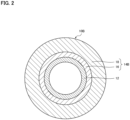
- FIG. 2 shows a cross-sectional view of an air brake tube 10B according to a second embodiment.
- the air brake tube 10B is different from the air brake tube 10A (see FIG. 1 ) in that an outer layer 14B includes a first outer layer 16 provided on the outer side of the inner layer 12 and a second outer layer 18 provided on an outer side of the first outer layer 16.
- the air brake tube 10B has a three-layer structure including the inner layer 12, the first outer layer 16, and the second outer layer 18.
- materials of the inner layer 12, the first outer layer 16, and the second outer layer 18 are also selected such that a hoop stress of the air brake tube 10B in an environment of 125°C is larger than 9.72 MPa and a tensile modulus of the air brake tube 10B in an environment of 23°C is less than 650 MPa.
- a proportion of a wall thickness of the inner layer 12 made of an unplasticized polyamide-based resin is 5% or more and 40% or less
- the inner layer 12 is made of an unplasticized polyamide-based resin that has a hoop stress of more than 9.72 MPa and 25 MPa or less at 125°C when made into a single-layer tube
- the outer layer 14B is made of a plasticized polyamide-based resin that has a hoop stress of 9.72 MPa or less at 125°C when made into a single-layer tube
- the unplasticized polyamide-based resin of the inner layer 12 and the plasticized polyamide-based resin of the outer layer 14B are made to have a melting point of 190°C or higher, or a deflection temperature under load when a bending stress of 1.80 MPa is applied in accordance with ISO 75 of 50°C or higher.
- the hoop stress of the air brake tube 10B in an environment of 125°C is larger than 9.72 MPa, and the tensile modulus of the air brake tube 10B in an environment of 23°C is less than 650 MPa. Therefore, it is possible to achieve both pressure resistance in a high temperature environment and workability of routing in a vehicle.
- the first outer layer 16 can be made of, for example, an inexpensive plasticized polyamide-based resin that is inferior in chemical resistance, wear resistance, and the like
- the second outer layer 18 can be made of a plasticized polyamide-based resin that is superior in chemical resistance, wear resistance, and the like to the first outer layer 16.
- a degree of freedom of selection of the plasticized polyamide-based resin used for the outer layer 14B is increased, and thus a wide range of design is possible.
- a tube sample is left to stand in an environment of 23°C/50% RH for 1 hour or longer and is then placed in oil at 125°C for 10 minutes to start a burst test.
- the tube sample is broken in 30 seconds to 60 seconds, and a maximum burst pressure is measured. Based on the measured maximum burst pressure, the hoop stress under an environment of 125°C is obtained using the hoop stress conversion equation (see Equation 1) defined in DIN 73378.
- the obtained hoop stress is the pressure resistance under an environment of 125°C.
- the obtained hoop stress is evaluated as " ⁇ "
- the obtained hoop stress is 9.72 MPa or less
- the obtained hoop stress is evaluated as "x”.
- a tube sample cut into a length of 170 mm is left to stand for 24 hours or longer in an environment of 23°C/50% RH, and is then set in the tensile testing device defined in JIS K7161-1 such that the distance between grips is 115 mm.
- the tensile test is started at a test speed of 1 mm/min in accordance with JIS K7161-1 in an environment of 23°C/50% RH, and the tensile load and the amount of increase in distance between grips are measured.
- the tensile stress is determined using the tensile stress calculation equation (see Equation 2) defined in JIS K7161-1. Further, based on the measured amount of increase in distance between grips and the initial distance between grips, a nominal strain is determined using the nominal strain calculation equation (see Equation 3) defined in JIS K7161-1. Based on the obtained tensile stress and nominal strain, the tensile modulus is determined using the tensile modulus calculation equation (see Equation 4) defined in JIS K7161-1.
- the obtained tensile modulus is the flexibility in an environment of 23°C.
- the obtained tensile modulus is evaluated as " ⁇ "
- the obtained tensile modulus is evaluated as " ⁇ "
- Examples I and Comparative Examples I air brake tubes each having an outer diameter of 8 mm and a wall thickness of 1 mm were molded, and the pressure resistance in an environment of 125°C and the flexibility in an environment of 23°C were evaluated.
- "-A", "-B", and "-C" were respectively added to ends of numbers of polyamide resins. The same applies to Examples II, Comparative Examples II, Examples III, Comparative Examples III, and Reference Examples to be described later.
- Example I-1 is an air brake tube having a two-layer structure in which an inner layer is made of an unplasticized polyamide 612 resin, an outer layer is made of a plasticized polyamide 612-A resin, and the inner layer and the outer layer respectively have wall thicknesses of 0.25 mm and 0.75 mm (a proportion of the wall thickness of the inner layer is 250).
- Example I-2 is an air brake tube having a two-layer structure in which an inner layer is made of an unplasticized polyamide 6-A resin, an outer layer is made of a plasticized polyamide 612-A resin, and the inner layer and the outer layer respectively have wall thicknesses of 0.4 mm and 0.6 mm (a proportion of the wall thickness of the inner layer is 40%).
- Example I-3 is an air brake tube having a three-layer structure in which an inner layer is made of an unplasticized polyamide 612 resin, a first outer layer is made of a plasticized polyamide 612-B resin, a second outer layer is made of a plasticized polyamide 612-A resin, and the inner layer, the first outer layer, and the second outer layer respectively have wall thicknesses of 0.2 mm, 0.2 mm, and 0.6 mm (a proportion of the wall thickness of the inner layer is 20%).
- Example I-4 is an air brake tube having a two-layer structure in which an inner layer is made of an unplasticized polyamide 66-A resin, an outer layer is made of a plasticized polyamide 612-A resin, and the inner layer and the outer layer respectively have wall thicknesses of 0.1 mm and 0.9 mm (a proportion of the wall thickness of the inner layer is 10%).
- Comparative Example I-1 is an air brake tube having a two-layer structure in which an inner layer is made of an unplasticized polyamide 612 resin, an outer layer is made of a plasticized polyamide 612-A resin, and the inner layer and the outer layer respectively have wall thicknesses of 0.5 mm and 0.5 mm (a proportion of the wall thickness of the inner layer is 50%).
- Comparative Example I-2 is an air brake tube having a two-layer structure in which an inner layer is made of an unplasticized polyamide 66-B resin, an outer layer is made of a plasticized polyamide 612-A resin, and the inner layer and the outer layer respectively have wall thicknesses of 0.1 mm and 0.9 mm (a proportion of the wall thickness of the inner layer is 10%).
- Comparative Example I-3 is an air brake tube having a two-layer structure in which an inner layer is made of an unplasticized polyamide 6-B resin, an outer layer is made of a plasticized polyamide 610-A resin, and the inner layer and the outer layer respectively have wall thicknesses of 0.4 mm and 0.6 mm (a proportion of the wall thickness of the inner layer is 40%).
- Comparative Example I-4 is a single-layer air brake tube made of a polyamide 1010 resin that satisfies the pressure resistance defined as PHLY in DIN 74324.
- Comparative Example I-5 is a single-layer air brake tube made of a plasticized polyamide 612-A resin.
- Comparative Example I-6 is an air brake tube having a two-layer structure in which an inner layer is made of an unplasticized polyamide 6-C resin, an outer layer is made of a plasticized polyamide 12 resin, and the inner layer and the outer layer respectively have wall thicknesses of 0.4 mm and 0.6 mm (a proportion of the wall thickness of the inner layer is 40%).
- Comparative Example I-7 is a single-layer air brake tube made of a plasticized polyamide 12 resin defined as PHLY in DIN 74324.
- Table 1 shows evaluation results of the pressure resistance and the flexibility of each of the air brake tubes in Examples I and Comparative Examples I.
- hoop stresses shown in columns of the inner layer and the outer layer are hoop stresses in an environment of 125°C when each material is made into a single-layer tube having an outer diameter of 8 mm and a wall thickness of 1 mm. Since the hoop stress is a characteristic that does not depend on a tube size and is determined only by the material, the same applies to Tables 2, 3, and 4, which will be described later.
- the deflection temperature under load is a deflection temperature under load when a bending stress of 1.80 MPa is applied in accordance with ISO 75.
- Example II-1 is an air brake tube having a two-layer structure in which an inner layer is made of an unplasticized polyamide 612 resin, an outer layer is made of a plasticized polyamide 612-A resin, and the inner layer and the outer layer respectively have wall thicknesses of 0.31 mm and 0.94 mm (a proportion of the wall thickness of the inner layer is 25%).
- Example II-2 is an air brake tube having a two-layer structure in which an inner layer is made of an unplasticized polyamide 6-A resin, an outer layer is made of a plasticized polyamide 612-A resin, and the inner layer and the outer layer respectively have wall thicknesses of 0.5 mm and 0.75 mm (a proportion of the wall thickness of the inner layer is 40%).
- Example II-3 is an air brake tube having a three-layer structure in which an inner layer is made of an unplasticized polyamide 612 resin, a first outer layer is made of a plasticized polyamide 612-B resin, a second outer layer is made of a plasticized polyamide 612-A resin, and the inner layer, the first outer layer, and the second outer layer respectively have wall thicknesses of 0.25 mm, 0.25 mm, and 0.75 mm (a proportion of the wall thickness of the inner layer is 20%).
- Example II-4 is an air brake tube having a two-layer structure in which an inner layer is made of an unplasticized polyamide 66-A resin, an outer layer is made of a plasticized polyamide 612-A resin, and the inner layer and the outer layer respectively have wall thicknesses of 0.12 mm and 1.13 mm (a proportion of the wall thickness of the inner layer is 10%).
- Comparative Example II-1 is an air brake tube having a two-layer structure in which an inner layer is made of an unplasticized polyamide 612 resin, an outer layer is made of a plasticized polyamide 612-A resin, and the inner layer and the outer layer respectively have wall thicknesses of 0.62 mm and 0.63 mm (a proportion of the wall thickness of the inner layer is 50%).
- Comparative Example II-2 is an air brake tube having a two-layer structure in which an inner layer is made of an unplasticized polyamide 66-B resin, an outer layer is made of a plasticized polyamide 612-A resin, and the inner layer and the outer layer respectively have wall thicknesses of 0.12 mm and 1.13 mm (a proportion of the wall thickness of the inner layer is 10%).
- Comparative Example II-3 is an air brake tube having a two-layer structure in which an inner layer is made of an unplasticized polyamide 6-B resin, an outer layer is made of a plasticized polyamide 610-A resin, and the inner layer and the outer layer respectively have wall thicknesses of 0.5 mm and 0.75 mm (a proportion of the wall thickness of the inner layer is 40%).
- Comparative Example II-4 is a single-layer air brake tube made of a polyamide 1010 resin that satisfies the pressure resistance defined as PHLY in DIN 74324.
- Comparative Example II-5 is a single-layer air brake tube made of a plasticized polyamide 612-A resin.
- Comparative Example II-6 is an air brake tube having a two-layer structure in which an inner layer is made of an unplasticized polyamide 6-C resin, an outer layer is made of a plasticized polyamide 12 resin, and the inner layer and the outer layer respectively have wall thicknesses of 0.5 mm and 0.75 mm (a proportion of the wall thickness of the inner layer is 40%).
- Comparative Example II-7 is a single-layer air brake tube made of a plasticized polyamide 12 resin defined as PHLY in DIN 74324.
- Table 2 shows evaluation results of the pressure resistance and the flexibility of each of the air brake tubes in Examples II and Comparative Examples II.
- Example III-1 is an air brake tube having a two-layer structure in which an inner layer is made of an unplasticized polyamide 612 resin, an outer layer is made of a plasticized polyamide 612-A resin, and the inner layer and the outer layer respectively have wall thicknesses of 0.38 mm and 1.12 mm (a proportion of the wall thickness of the inner layer is 250).
- Example III-2 is an air brake tube having a two-layer structure in which an inner layer is made of an unplasticized polyamide 6-A resin, an outer layer is made of a plasticized polyamide 612-A resin, and the inner layer and the outer layer respectively have wall thicknesses of 0.6 mm and 0.9 mm (a proportion of the wall thickness of the inner layer is 40%).
- Example III-3 is an air brake tube having a three-layer structure in which an inner layer is made of an unplasticized polyamide 612 resin, a first outer layer is made of a plasticized polyamide 612-B resin, a second outer layer is made of a plasticized polyamide 612-A resin, and the inner layer, the first outer layer, and the second outer layer respectively have wall thicknesses of 0.3 mm, 0.3 mm, and 0.9 mm (a proportion of the wall thickness of the inner layer is 200).
- Example III-4 is an air brake tube having a two-layer structure in which an inner layer is made of an unplasticized polyamide 66-A resin, an outer layer is made of a plasticized polyamide 612-A resin, and the inner layer and the outer layer respectively have wall thicknesses of 0.15 mm and 1.35 mm (a proportion of the wall thickness of the inner layer is 10%).
- Comparative Example III-1 is an air brake tube having a two-layer structure in which an inner layer is made of an unplasticized polyamide 612 resin, an outer layer is made of a plasticized polyamide 612-A resin, and the inner layer and the outer layer respectively have wall thicknesses of 0.75 mm and 0.75 mm (a proportion of the wall thickness of the inner layer is 50%).
- Comparative Example III-2 is an air brake tube having a two-layer structure in which an inner layer is made of an unplasticized polyamide 66-B resin, an outer layer is made of a plasticized polyamide 612-A resin, and the inner layer and the outer layer respectively have wall thicknesses of 0.15 mm and 1.35 mm (a proportion of the wall thickness of the inner layer is 10%).
- Comparative Example III-3 is an air brake tube having a two-layer structure in which an inner layer is made of an unplasticized polyamide 6-B resin, an outer layer is made of a plasticized polyamide 610-A resin, and the inner layer and the outer layer respectively have wall thicknesses of 0.6 mm and 0.9 mm (a proportion of the wall thickness of the inner layer is 40%).
- Comparative Example III-4 is a single-layer air brake tube made of a polyamide 1010 resin that satisfies the pressure resistance defined as PHLY in DIN 74324.
- Comparative Example III-5 is a single-layer air brake tube made of a plasticized polyamide 612-A resin.
- Comparative Example III-6 is an air brake tube having a two-layer structure in which an inner layer is made of an unplasticized polyamide 6-C resin, an outer layer is made of a plasticized polyamide 12 resin, and the inner layer and the outer layer respectively have wall thicknesses of 0.6 mm and 0.9 mm (a proportion of the wall thickness of the inner layer is 40%).
- Comparative Example III-7 is a single-layer air brake tube made of a plasticized polyamide 12 resin defined as PHLY in DIN 74324.
- Table 3 shows evaluation results of the pressure resistance and the flexibility of each of the air brake tubes in Examples III and Comparative Examples III.
- the unplasticized polyamide 66-B resin of the inner layer has a hoop stress of 28.5 MPa at 125°C when made into a single-layer tube, which is more than 25 MPa. Therefore, the flexibility of the unplasticized polyamide-based resin of the inner layer cannot be fully supplemented by the plasticized polyamide-based resin of the outer layer, and the flexibility cannot be satisfied.
- the plasticized polyamide 610-A resin of the outer layer has a hoop stress of 11.25 MPa at 125°C when made into a single-layer tube, which is more than 9.72 MPa. Therefore, the plasticized polyamide-based resin of the outer layer cannot supplement the flexibility of the unplasticized polyamide-based resin of the inner layer, and the flexibility cannot be satisfied.
- the unplasticized polyamide 6-C resin of the inner layer has a deflection temperature under load when a bending stress of 1.80 MPa is applied in accordance with ISO 75 of lower than 50°C
- the plasticized polyamide 12 resin of the outer layer has a melting point of lower than 190°C and a deflection temperature under load when a bending stress of 1.80 MPa is applied in accordance with ISO 75 of lower than 50°C.
- a resin having a low melting point or a low deflection temperature under load has a large decrease in stress from room temperature to a high temperature as compared with a resin having a high melting point or a high deflection temperature under load. Therefore, the pressure resistance cannot be satisfied.
- the air brake tube is a single layer.
- the plasticized polyamide 12 resin defined as PHLY in DIN 74324 has a hoop stress of 9.72 MPa or less at 125°C when made into a single-layer tube, a melting point of lower than 190°C, and a deflection temperature under load when a bending stress of 1.80 MPa is applied in accordance with ISO 75 of lower than 50°C. Therefore, the pressure resistance cannot be satisfied.
- the inner layer is made of the unplasticized polyamide-based resin
- the outer layer is made of the plasticized polyamide-based resin
- the proportion of the wall thickness of the inner layer to a total wall thickness of the tube is 5% or more and 40% or less
- the unplasticized polyamide-based resin has a hoop stress of more than 9.72 MPa and 25 MPa or less at 125°C when made into a single-layer tube
- the plasticized polyamide-based resin has a hoop stress of 9.72 MPa or less at 125°C when made into a single-layer tube
- the unplasticized polyamide-based resin and the plasticized polyamide-based resin have a melting point of 190°C or higher or a deflection temperature under load when a bending stress of 1.80 MPa is applied in accordance with ISO 75 of 50°C or higher. Therefore, it is possible to satisfy both the pressure resistance and the flexibility, and it is possible to achieve both the pressure resistance in a high temperature environment and the workability of routing in accordance with ISO 75
Landscapes
- Engineering & Computer Science (AREA)
- Mechanical Engineering (AREA)
- General Engineering & Computer Science (AREA)
- Transportation (AREA)
- Laminated Bodies (AREA)
- Rigid Pipes And Flexible Pipes (AREA)
Abstract
Description
- The present invention relates to an air brake tube.
- In an air brake system used for a truck, a bus, or the like, a metal pipe or a polyamide-based resin tube is used. From the viewpoint of weight reduction and ease of a routing work, the use of the polyamide-based resin tube is increasing.
- An air brake tube is used for flow of high-pressure air in a high temperature environment, and is thus required to have heat resistance and pressure resistance. As standards for the highest heat and pressure resistance requirements, DIN 74324, which is a German industry standard, defines a maximum operating temperature of 100°C and a maximum operating pressure of 1,250 kPa. In recent years, a temperature in the vicinity of the air brake tube has been increased, and as a standard for a higher temperature environment, ISO 7628, which is an international industrial standard, defines a maximum operating temperature of 125°C and a maximum operating pressure of 1,250 kPa.
- In order to improve pressure resistance at the maximum operating temperature defined in ISO 7628, a multilayer tube including an innermost layer made of a polyamide-based resin, an outer layer made of a polyester-based elastomer, and an adhesive layer provided between the innermost layer and the outer layer has been proposed (Patent Literature 1). In Patent Literature 1, by using, for the outer layer, the polyester-based elastomer which has a melting point higher than that of a polyamide-based resin defined as a material for a tube in DIN 74324, the pressure resistance in a high temperature environment is improved.
- Patent Literature 1:
JPH08-247344A - The polyester-based elastomer disclosed in Patent Literature 1 has rigidity higher than that of a polyamide-based resin generally used as an air brake tube. Therefore, as disclosed in Patent Literature 1, the multilayer tube including the layer made of the polyester-based elastomer has flexibility lower than that of a single-layer tube made of a polyamide-based resin. As a result, it is extremely difficult to perform a routing work in a vehicle such as a truck and a bus. In the related art, a single-layer tube made of a polyamide-based resin in accordance with DIN 74324, which is generally applied as the air brake tube, cannot satisfy pressure resistance strength in an environment of 125°C defined in category 3 in accordance with ISO 7628. On the other hand, by applying a polyamide-based resin having rigidity higher than that of the polyamide-based resin in accordance with DIN 74324, it is possible to satisfy the pressure resistance strength in an environment of 125°C defined in category 3 in accordance with ISO 7628, but in this case, since the polyamide-based resin having higher rigidity is used, it is extremely difficult to perform a routing work in the vehicle.
- An object of the present invention is to provide an air brake tube capable of achieving both pressure resistance in a high temperature environment and workability of routing in a vehicle.
- An air brake tube according to the present invention has a multilayer structure, and has a hoop stress of more than 9.72 MPa in an environment of 125°C and a tensile modulus of less than 650 MPa in an environment of 23°C.
- According to the present invention, since the hoop stress in an environment of 125°C is more than 9.72 MPa, the air brake tube has pressure resistance in an environment of 125°C higher than pressure resistance in an environment of 125°C for a single-layer tube made of a polyamide-based resin in accordance with DIN 74324. Further, since the tensile modulus in an environment of 23°C is less than 650 MPa, the air brake tube has flexibility in an environment of 23°C higher than flexibility in an environment of 23°C for a single-layer tube made of a highly rigid polyamide-based resin that can satisfy the pressure resistance strength in an environment of 125°C defined in category 3 in accordance with ISO 7628. Therefore, it is possible to achieve both pressure resistance in a high temperature environment and workability of routing in a vehicle.
-
- [
FIG. 1] FIG. 1 is a cross-sectional view showing an air brake tube according to a first embodiment. - [
FIG. 2] FIG. 2 is a cross-sectional view showing an air brake tube according to a second embodiment. - Hereinafter, embodiments of the present invention will be described in detail with reference to the drawings. The embodiments to be described below are examples of the present invention, and the present invention is not limited thereto. In the following description relating to each embodiment, similar components will be denoted by the same reference numerals, and the description will be omitted as appropriate.
-
FIG. 1 shows a cross-sectional view of anair brake tube 10A according to a first embodiment. Theair brake tube 10A has a multilayer structure. The multilayer structure includes a hollowinner layer 12 and anouter layer 14A provided on an outer side of theinner layer 12. - Materials of the
inner layer 12 and theouter layer 14A are selected such that a hoop stress of theair brake tube 10A in an environment of 125°C is larger than 9.72 MPa and a tensile modulus of theair brake tube 10A in an environment of 23°C is less than 650 MPa. - Here, indexes of pressure resistance and flexibility are described in detail.
- The index of the pressure resistance is determined based on a burst pressure in accordance with ISO 7628 determined as a standard compatible with a higher temperature environment. In category 3 in accordance with ISO 7628, the burst pressure in an environment of 125°C defined as a maximum operating temperature is defined as 2.5 MPa. The burst pressure of 2.5 MPa is converted into the hoop stress using a hoop stress conversion equation defined in DIN 73378. The hoop stress obtained by conversion is the index of the pressure resistance.
- In DIN 73378, the hoop stress conversion equation is defined as follows.

- σ: hoop stress (MPa)
- p: burst pressure (MPa)
- d: tube outer diameter (mm)
- s: tube wall thickness (mm)
- In ISO 7628 and DIN 74324, the tube outer diameter, the tube wall thickness, and dimensional tolerances thereof are determined for each nominal tube diameter. When the hoop stress σ is determined using the hoop stress conversion equation in DIN 73378 based on the tube outer diameter and tube wall thickness, which are conditions that are most likely to cause burst within a dimensional tolerance, for a commonly used nominal tube diameter, the hoop stress corresponding to the burst pressure of 2.5 MPa is 9.72 MPa. That is, the hoop stress of 9.72 MPa is a reference value for determining whether the pressure resistance is satisfied.
- The tensile modulus, which indicates difficulty of deformation, is used as the index of the flexibility. The lower the tensile modulus, the higher the flexibility. For the tensile modulus serving as a reference value for determining whether the flexibility is satisfied, a measurement result of the tensile modulus of a single-layer tube made of a polyamide 1010 (PA1010) resin that satisfies the pressure resistance defined as PHLY in DIN 74324 is used.
- In measurement of the tensile modulus, a sample of the single-layer tube made of the polyamide 1010 resin that satisfies the pressure resistance defined as PHLY in DIN 74324 and cut into a length of 170 mm is left to stand in an environment of 23°C/50% RH for 24 hours or longer, and then set in a tensile testing device defined in Japan industrial standard JIS K7161-1 such that a distance between grips is 115 mm. A tensile test is started at a test speed of 1 mm/min in accordance with JIS K7161-1 in an environment of 23°C/50% RH, and a tensile load and an amount of increase in distance between grips are measured.
- Based on the measured tensile load and an initial cross-sectional area of the tube sample, a tensile stress is determined using the following tensile stress calculation equation defined in JIS K7161-1.

- σ: tensile stress (MPa)
- F: tension load (N)
- A: initial cross-sectional area (mm2) of tube sample
- Based on the measured amount of increase in distance between grips and an initial distance between grips, a nominal strain is determined using the following nominal strain calculation equation defined in JIS K7161-1.

- εt: nominal strain (dimensionless)
- L: initial distance between grips (mm)
- Lt: amount of increase in distance between grips (mm)
- Based on the obtained tensile stress and nominal strain, the tensile modulus is determined using the following tensile modulus calculation equation defined in JIS K7161-1.

- Et: tensile modulus (MPa)
- σ1: tensile stress (MPa) at nominal strain ε1 of 0.0005
- σ2: tensile stress (MPa) at nominal strain ε2 of 0.0025
- The single-layer tube made of the polyamide 1010 resin that satisfies the pressure resistance defined as PHLY in DIN 74324 has a tensile modulus of 650 MPa in an environment of 23°C/50% RH. That is, the tensile modulus of 650 MPa is a reference value for determining whether the flexibility is satisfied.
- As described above, the reference value of the pressure resistance is the hoop stress of 9.72 MPa, and the reference value of the flexibility is the tensile modulus of 650 MPa. The materials of the
inner layer 12 and theouter layer 14A of theair brake tube 10A are selected such that the hoop stress of theair brake tube 10A in an environment of 125°C is larger than 9.72 MPa and the tensile modulus of theair brake tube 10A in an environment of 23°C is less than 650 MPa. - In the present embodiment, the
inner layer 12 is made of an unplasticized polyamide-based resin, and theouter layer 14A is made of a plasticized polyamide-based resin. With this structure, pressure resistance of theouter layer 14A made of the plasticized polyamide-based resin is supplemented by the unplasticized polyamide-based resin of theinner layer 12, and flexibility of theinner layer 12 made of the unplasticized polyamide-based resin is supplemented by the plasticized polyamide-based resin of theouter layer 14A. - When the
inner layer 12 is made of the unplasticized polyamide-based resin, a wall thickness of theinner layer 12 is thinner and pressure resistance thereof is higher than those in the case in which theouter layer 14A is made of the unplasticized polyamide-based resin. Therefore, the wall thickness of the plasticized polyamide-based resin of theouter layer 14A can be increased, and a supplementary effect of the plasticized polyamide-based resin on flexibility can be enhanced. - When a proportion of the wall thickness of the
inner layer 12 to a total wall thickness of theinner layer 12 and theouter layer 14A (hereinafter also simply referred to as "a proportion of the wall thickness of theinner layer 12") is too large, the flexibility of the unplasticized polyamide-based resin of theinner layer 12 is not supplemented by the plasticized polyamide-based resin of theouter layer 14A, and the flexibility cannot be satisfied. Therefore, the proportion of the wall thickness of theinner layer 12 is set such that the flexibility of the unplasticized polyamide-based resin of theinner layer 12 is supplemented by the plasticized polyamide-based resin of theouter layer 14A. When the proportion of the wall thickness of theinner layer 12 is less than 5%, it is difficult to stably mold theinner layer 12, and thus the proportion of the wall thickness of theinner layer 12 is preferably 5% or more. - In the case in which the unplasticized polyamide-based resin of the
inner layer 12 has an excessively large hoop stress at 125°C when made into a single-layer tube, the plasticized polyamide-based resin of theouter layer 14A cannot fully supplement the flexibility of the unplasticized polyamide-based resin of theinner layer 12, and the flexibility cannot be satisfied. Similarly, in the case in which the plasticized polyamide-based resin of theouter layer 14A has an excessively large hoop stress at 125°C when made into a single-layer tube, the plasticized polyamide-based resin of theouter layer 14A cannot fully supplement the flexibility of the unplasticized polyamide-based resin of theinner layer 12, and the flexibility cannot be satisfied. Further, in the case in which the unplasticized polyamide-based resin of theinner layer 12 has an excessively small hoop stress at 125°C when made into a single-layer tube, the unplasticized polyamide-based resin of theinner layer 12 cannot supplement the pressure resistance of the plasticized polyamide-based resin of theouter layer 14A, and the pressure resistance cannot be satisfied. Therefore, the hoop stresses at 125°C when the resins are made into a single-layer tube are separately set such that the flexibility of the unplasticized polyamide-based resin of theinner layer 12 is supplemented by the plasticized polyamide-based resin of theouter layer 14A and the pressure resistance of the plasticized polyamide-based resin of theouter layer 14A is supplemented by the unplasticized polyamide-based resin of theinner layer 12. - In a polyamide-based resin, a decrease in stress from room temperature to a high temperature depends on a melting point or a deflection temperature under load. Specifically, the lower the melting point or the deflection temperature under load, the larger the decrease in stress from room temperature to a high temperature. Therefore, when the melting point or the deflection temperature under load of the polyamide-based resin used for each of the
inner layer 12 and theouter layer 14A is too low, the pressure resistance under a high temperature environment cannot be satisfied due to a decrease in stress from 23°C to 125°C. Therefore, the melting point or the deflection temperature under load is set such that the decrease in stress of each of theinner layer 12 and theouter layer 14A from 23°C to 125°C is small. - A deflection temperature under load defined in ISO 75 can be used as the deflection temperature under load. ISO 75 is one of test methods for evaluating heat resistance of a synthetic resin. In ISO 75, the deflection temperature under load is defined as a temperature at which an increase in bending strain is 0.2% after a bending stress of 1.80 MPa is applied to a test piece and a temperature is raised at a rate of 120°C/hr.
- In the
air brake tube 10A, the proportion of the wall thickness of theinner layer 12 made of the unplasticized polyamide-based resin is 5% or more and 40% or less, theinner layer 12 is made of an unplasticized polyamide-based resin that has a hoop stress of more than 9.72 MPa and 25 MPa or less at 125°C when made into a single-layer tube, theouter layer 14A is made of a plasticized polyamide-based resin that has a hoop stress of 9.72 MPa or less at 125°C when made into a single-layer tube, and the unplasticized polyamide-based resin of theinner layer 12 and the plasticized polyamide-based resin of theouter layer 14A are made to have a melting point of 190°C or higher, or a deflection temperature under load when a bending stress of 1.80 MPa is applied in accordance with ISO 75 of 50°C or higher. Therefore, the hoop stress of theair brake tube 10A in an environment of 125°C is larger than 9.72 MPa, and the tensile modulus of theair brake tube 10A in an environment of 23°C is less than 650 MPa. Therefore, it is possible to achieve both pressure resistance in a high temperature environment and workability of routing in a vehicle. -
FIG. 2 shows a cross-sectional view of anair brake tube 10B according to a second embodiment. Theair brake tube 10B is different from theair brake tube 10A (seeFIG. 1 ) in that anouter layer 14B includes a firstouter layer 16 provided on the outer side of theinner layer 12 and a secondouter layer 18 provided on an outer side of the firstouter layer 16. In other words, theair brake tube 10B has a three-layer structure including theinner layer 12, the firstouter layer 16, and the secondouter layer 18. - In the
air brake tube 10B, materials of theinner layer 12, the firstouter layer 16, and the secondouter layer 18 are also selected such that a hoop stress of theair brake tube 10B in an environment of 125°C is larger than 9.72 MPa and a tensile modulus of theair brake tube 10B in an environment of 23°C is less than 650 MPa. - Similarly, in the
air brake tube 10B, a proportion of a wall thickness of theinner layer 12 made of an unplasticized polyamide-based resin is 5% or more and 40% or less, theinner layer 12 is made of an unplasticized polyamide-based resin that has a hoop stress of more than 9.72 MPa and 25 MPa or less at 125°C when made into a single-layer tube, theouter layer 14B is made of a plasticized polyamide-based resin that has a hoop stress of 9.72 MPa or less at 125°C when made into a single-layer tube, and the unplasticized polyamide-based resin of theinner layer 12 and the plasticized polyamide-based resin of theouter layer 14B are made to have a melting point of 190°C or higher, or a deflection temperature under load when a bending stress of 1.80 MPa is applied in accordance with ISO 75 of 50°C or higher. Therefore, the hoop stress of theair brake tube 10B in an environment of 125°C is larger than 9.72 MPa, and the tensile modulus of theair brake tube 10B in an environment of 23°C is less than 650 MPa. Therefore, it is possible to achieve both pressure resistance in a high temperature environment and workability of routing in a vehicle. - The first
outer layer 16 can be made of, for example, an inexpensive plasticized polyamide-based resin that is inferior in chemical resistance, wear resistance, and the like, and the secondouter layer 18 can be made of a plasticized polyamide-based resin that is superior in chemical resistance, wear resistance, and the like to the firstouter layer 16. In this case, it is possible to improve chemical resistance, wear resistance, and the like while reducing a cost of theair brake tube 10B. In this way, in theair brake tube 10B, a degree of freedom of selection of the plasticized polyamide-based resin used for theouter layer 14B is increased, and thus a wide range of design is possible. - Hereinafter, the present invention will be described in detail based on Examples. Evaluation methods for pressure resistance and flexibility of air brake tubes obtained in the following Examples and Comparative Examples are as follows.
- A tube sample is left to stand in an environment of 23°C/50% RH for 1 hour or longer and is then placed in oil at 125°C for 10 minutes to start a burst test. In the burst test, the tube sample is broken in 30 seconds to 60 seconds, and a maximum burst pressure is measured. Based on the measured maximum burst pressure, the hoop stress under an environment of 125°C is obtained using the hoop stress conversion equation (see Equation 1) defined in DIN 73378.
- The obtained hoop stress is the pressure resistance under an environment of 125°C. When the obtained hoop stress is more than 9.72 MPa, the obtained hoop stress is evaluated as "∘", and when the obtained hoop stress is 9.72 MPa or less, the obtained hoop stress is evaluated as "x".
- A tube sample cut into a length of 170 mm is left to stand for 24 hours or longer in an environment of 23°C/50% RH, and is then set in the tensile testing device defined in JIS K7161-1 such that the distance between grips is 115 mm. The tensile test is started at a test speed of 1 mm/min in accordance with JIS K7161-1 in an environment of 23°C/50% RH, and the tensile load and the amount of increase in distance between grips are measured.
- Based on the measured tensile load and the initial cross-sectional area of the tube sample, the tensile stress is determined using the tensile stress calculation equation (see Equation 2) defined in JIS K7161-1. Further, based on the measured amount of increase in distance between grips and the initial distance between grips, a nominal strain is determined using the nominal strain calculation equation (see Equation 3) defined in JIS K7161-1. Based on the obtained tensile stress and nominal strain, the tensile modulus is determined using the tensile modulus calculation equation (see Equation 4) defined in JIS K7161-1.
- The obtained tensile modulus is the flexibility in an environment of 23°C. When the obtained tensile modulus is less than 650 MPa, the obtained tensile modulus is evaluated as "∘", and when the obtained tensile modulus is 650 MPa or more, the obtained tensile modulus is evaluated as "×".
- In Examples I and Comparative Examples I, air brake tubes each having an outer diameter of 8 mm and a wall thickness of 1 mm were molded, and the pressure resistance in an environment of 125°C and the flexibility in an environment of 23°C were evaluated. In order to identify resin materials of the same polyamide type having different hoop stresses at 125°C, "-A", "-B", and "-C" were respectively added to ends of numbers of polyamide resins. The same applies to Examples II, Comparative Examples II, Examples III, Comparative Examples III, and Reference Examples to be described later.
- Example I-1 is an air brake tube having a two-layer structure in which an inner layer is made of an unplasticized polyamide 612 resin, an outer layer is made of a plasticized polyamide 612-A resin, and the inner layer and the outer layer respectively have wall thicknesses of 0.25 mm and 0.75 mm (a proportion of the wall thickness of the inner layer is 250). Example I-2 is an air brake tube having a two-layer structure in which an inner layer is made of an unplasticized polyamide 6-A resin, an outer layer is made of a plasticized polyamide 612-A resin, and the inner layer and the outer layer respectively have wall thicknesses of 0.4 mm and 0.6 mm (a proportion of the wall thickness of the inner layer is 40%). Example I-3 is an air brake tube having a three-layer structure in which an inner layer is made of an unplasticized polyamide 612 resin, a first outer layer is made of a plasticized polyamide 612-B resin, a second outer layer is made of a plasticized polyamide 612-A resin, and the inner layer, the first outer layer, and the second outer layer respectively have wall thicknesses of 0.2 mm, 0.2 mm, and 0.6 mm (a proportion of the wall thickness of the inner layer is 20%). Example I-4 is an air brake tube having a two-layer structure in which an inner layer is made of an unplasticized polyamide 66-A resin, an outer layer is made of a plasticized polyamide 612-A resin, and the inner layer and the outer layer respectively have wall thicknesses of 0.1 mm and 0.9 mm (a proportion of the wall thickness of the inner layer is 10%).
- Comparative Example I-1 is an air brake tube having a two-layer structure in which an inner layer is made of an unplasticized polyamide 612 resin, an outer layer is made of a plasticized polyamide 612-A resin, and the inner layer and the outer layer respectively have wall thicknesses of 0.5 mm and 0.5 mm (a proportion of the wall thickness of the inner layer is 50%). Comparative Example I-2 is an air brake tube having a two-layer structure in which an inner layer is made of an unplasticized polyamide 66-B resin, an outer layer is made of a plasticized polyamide 612-A resin, and the inner layer and the outer layer respectively have wall thicknesses of 0.1 mm and 0.9 mm (a proportion of the wall thickness of the inner layer is 10%). Comparative Example I-3 is an air brake tube having a two-layer structure in which an inner layer is made of an unplasticized polyamide 6-B resin, an outer layer is made of a plasticized polyamide 610-A resin, and the inner layer and the outer layer respectively have wall thicknesses of 0.4 mm and 0.6 mm (a proportion of the wall thickness of the inner layer is 40%). Comparative Example I-4 is a single-layer air brake tube made of a polyamide 1010 resin that satisfies the pressure resistance defined as PHLY in DIN 74324. Comparative Example I-5 is a single-layer air brake tube made of a plasticized polyamide 612-A resin. Comparative Example I-6 is an air brake tube having a two-layer structure in which an inner layer is made of an unplasticized polyamide 6-C resin, an outer layer is made of a
plasticized polyamide 12 resin, and the inner layer and the outer layer respectively have wall thicknesses of 0.4 mm and 0.6 mm (a proportion of the wall thickness of the inner layer is 40%). Comparative Example I-7 is a single-layer air brake tube made of aplasticized polyamide 12 resin defined as PHLY in DIN 74324. - Table 1 shows evaluation results of the pressure resistance and the flexibility of each of the air brake tubes in Examples I and Comparative Examples I. In Table 1, hoop stresses shown in columns of the inner layer and the outer layer (the first outer layer and the second outer layer) are hoop stresses in an environment of 125°C when each material is made into a single-layer tube having an outer diameter of 8 mm and a wall thickness of 1 mm. Since the hoop stress is a characteristic that does not depend on a tube size and is determined only by the material, the same applies to Tables 2, 3, and 4, which will be described later. The deflection temperature under load is a deflection temperature under load when a bending stress of 1.80 MPa is applied in accordance with ISO 75. The same applies to Tables 2, 3, and 4, which will be described later.
[Table 1] Inner layer/single layer Outer layer Proportion % of wall thickness of inner layer Flexibility Pressure resistance Material Wall thickness mm Hoop stress MPa Melting point/deflection temperature under load °C Outer layer type Material Wall thickness mm Hoop stress MPa Melting point/deflecti on temperature under load °C Example I 1 Unplasticized PA612 0.25 16.20 190 or higher/50 or higher - Plasticized PA612-A 0.75 7.40 190 or higher/50 or higher 25 ○ ○ 2 Unplasticized PA6-A 0.4 12.80 190 or higher/50 or higher - Plasticized PA612-A 0.6 7.40 190 or higher/50 or higher 40 ○ ○ 3 Unplasticized PA612 0.2 16.20 190 or higher/50 or higher First Plasticized PA612-B 0.2 8.75 190 or higher/50 or higher 20 ○ ○ Second Plasticized PA612-A 0.6 7.40 190 or higher/50 or higher 4 Unplasticized PA66-A 0.1 25.00 190 or higher/50 or higher - Plasticized PA612-A 0.9 7.40 190 or higher/50 or higher 10 ○ ○ Comparati ve Example I 1 Unplasticized PA612 0.5 16.20 190 or higher/50 or higher - Plasticized PA612-A 0.5 7.40 190 or higher/50 or higher 50 × ○ 2 Unplasticized PA66-B 0.1 28.50 190 or higher/50 or higher - Plasticized PA612-A 0.9 7.40 190 or higher/50 or higher 10 × ○ 3 Unplasticized PA6-B 0.4 9.80 190 or higher/50 or higher - Plasticized PA610-A 0.6 11.25 190 or higher/50 or higher 40 × ○ 4 PA1010 1 10.15 190 or higher/50 or higher - - - - - 100 × ○ 5 Plasticized PA612-A 1 7.40 190 or higher/50 or higher - - - - - 100 ○ × 6 Unplasticized PA6-C 0.4 9.75 190 or higher/lower than 50 - Plasticized PA12 0.6 7.30 Lower than 190/lower than 50 40 ○ × 7 Plasticized PA12 1 7.30 Lower than 190/lower than 50 - - - - - 100 ○ × - In Examples II and Comparative Examples II, air brake tubes each having an outer diameter of 10 mm and a wall thickness of 1.25 mm were molded, and the pressure resistance under an environment of 125°C and the flexibility under an environment of 23°C were evaluated.
- Example II-1 is an air brake tube having a two-layer structure in which an inner layer is made of an unplasticized polyamide 612 resin, an outer layer is made of a plasticized polyamide 612-A resin, and the inner layer and the outer layer respectively have wall thicknesses of 0.31 mm and 0.94 mm (a proportion of the wall thickness of the inner layer is 25%). Example II-2 is an air brake tube having a two-layer structure in which an inner layer is made of an unplasticized polyamide 6-A resin, an outer layer is made of a plasticized polyamide 612-A resin, and the inner layer and the outer layer respectively have wall thicknesses of 0.5 mm and 0.75 mm (a proportion of the wall thickness of the inner layer is 40%). Example II-3 is an air brake tube having a three-layer structure in which an inner layer is made of an unplasticized polyamide 612 resin, a first outer layer is made of a plasticized polyamide 612-B resin, a second outer layer is made of a plasticized polyamide 612-A resin, and the inner layer, the first outer layer, and the second outer layer respectively have wall thicknesses of 0.25 mm, 0.25 mm, and 0.75 mm (a proportion of the wall thickness of the inner layer is 20%). Example II-4 is an air brake tube having a two-layer structure in which an inner layer is made of an unplasticized polyamide 66-A resin, an outer layer is made of a plasticized polyamide 612-A resin, and the inner layer and the outer layer respectively have wall thicknesses of 0.12 mm and 1.13 mm (a proportion of the wall thickness of the inner layer is 10%).
- Comparative Example II-1 is an air brake tube having a two-layer structure in which an inner layer is made of an unplasticized polyamide 612 resin, an outer layer is made of a plasticized polyamide 612-A resin, and the inner layer and the outer layer respectively have wall thicknesses of 0.62 mm and 0.63 mm (a proportion of the wall thickness of the inner layer is 50%). Comparative Example II-2 is an air brake tube having a two-layer structure in which an inner layer is made of an unplasticized polyamide 66-B resin, an outer layer is made of a plasticized polyamide 612-A resin, and the inner layer and the outer layer respectively have wall thicknesses of 0.12 mm and 1.13 mm (a proportion of the wall thickness of the inner layer is 10%). Comparative Example II-3 is an air brake tube having a two-layer structure in which an inner layer is made of an unplasticized polyamide 6-B resin, an outer layer is made of a plasticized polyamide 610-A resin, and the inner layer and the outer layer respectively have wall thicknesses of 0.5 mm and 0.75 mm (a proportion of the wall thickness of the inner layer is 40%). Comparative Example II-4 is a single-layer air brake tube made of a polyamide 1010 resin that satisfies the pressure resistance defined as PHLY in DIN 74324. Comparative Example II-5 is a single-layer air brake tube made of a plasticized polyamide 612-A resin. Comparative Example II-6 is an air brake tube having a two-layer structure in which an inner layer is made of an unplasticized polyamide 6-C resin, an outer layer is made of a
plasticized polyamide 12 resin, and the inner layer and the outer layer respectively have wall thicknesses of 0.5 mm and 0.75 mm (a proportion of the wall thickness of the inner layer is 40%). Comparative Example II-7 is a single-layer air brake tube made of aplasticized polyamide 12 resin defined as PHLY in DIN 74324. - Table 2 shows evaluation results of the pressure resistance and the flexibility of each of the air brake tubes in Examples II and Comparative Examples II.
[Table 2] Inner layer/single layer Outer layer Proportion % of wall thickness of inner layer Flexibility Pressure resistance Material Wall thickness mm Hoop stress MPa Melting point/deflecti on temperature under load °C Outer layer type Material Wall thickness mm Hoop stress MPa Melting point/deflection temperature under load °C Example II 1 Unplasticized PA612 0.31 16.20 190 or higher/50 or higher - Plasticized PA612-A 0.94 7.40 190 or higher/50 or higher 25 ○ ○ 2 Unplasticized PA6-A 0.5 12.80 190 or higher/50 or higher - Plasticized PA612-A 0.75 7.40 190 or higher/50 or higher 40 ○ ○ 3 Unplasticized PA612 0.25 16.20 190 or higher/50 or higher First Plasticized PA612-B 0.25 8.75 190 or higher/50 or higher 20 ○ ○ Second Plasticized PA612-A 0.75 7.40 190 or higher/50 or higher 4 Unplasticized PA66-A 0.12 25.00 190 or higher/50 or higher - Plasticized PA612-A 1.13 7.40 190 or higher/50 or higher 10 ○ ○ Comparati ve Example II 1 Unplasticized PA612 0.62 16.20 190 or higher/50 or higher - Plasticized PA612-A 0.63 7.40 190 or higher/50 or higher 50 × ○ 2 Unplasticized PA66-B 0.12 28.50 190 or higher/50 or higher - Plasticized PA612-A 1.13 7.40 190 or higher/50 or higher 10 × ○ 3 Unplasticized PA6-B 0.5 9.80 190 or higher/50 or higher - Plasticized PA610-A 0.75 11.25 190 or higher/50 or higher 40 × ○ 4 PA1010 1.25 10.15 190 or higher/50 or higher - - - - - 100 × ○ 5 Plasticized PA612-A 1.25 7.40 190 or higher/50 or higher - - - - - 100 ○ × 6 Unplasticized PA6-C 0.5 9.75 190 or higher/lower than 50 - Plasticized PA12 0.75 7.30 Lower than 190/lower than 50 40 ○ × 7 Plasticized PA12 1.25 7.30 Lower than 190/lower than 50 - - - - - 100 ○ × - In Examples III and Comparative Examples III, air brake tubes each having an outer diameter of 12 mm and a wall thickness of 1.5 mm were molded, and the pressure resistance under an environment of 125°C and the flexibility under an environment of 23°C were evaluated.
- Example III-1 is an air brake tube having a two-layer structure in which an inner layer is made of an unplasticized polyamide 612 resin, an outer layer is made of a plasticized polyamide 612-A resin, and the inner layer and the outer layer respectively have wall thicknesses of 0.38 mm and 1.12 mm (a proportion of the wall thickness of the inner layer is 250). Example III-2 is an air brake tube having a two-layer structure in which an inner layer is made of an unplasticized polyamide 6-A resin, an outer layer is made of a plasticized polyamide 612-A resin, and the inner layer and the outer layer respectively have wall thicknesses of 0.6 mm and 0.9 mm (a proportion of the wall thickness of the inner layer is 40%). Example III-3 is an air brake tube having a three-layer structure in which an inner layer is made of an unplasticized polyamide 612 resin, a first outer layer is made of a plasticized polyamide 612-B resin, a second outer layer is made of a plasticized polyamide 612-A resin, and the inner layer, the first outer layer, and the second outer layer respectively have wall thicknesses of 0.3 mm, 0.3 mm, and 0.9 mm (a proportion of the wall thickness of the inner layer is 200). Example III-4 is an air brake tube having a two-layer structure in which an inner layer is made of an unplasticized polyamide 66-A resin, an outer layer is made of a plasticized polyamide 612-A resin, and the inner layer and the outer layer respectively have wall thicknesses of 0.15 mm and 1.35 mm (a proportion of the wall thickness of the inner layer is 10%).
- Comparative Example III-1 is an air brake tube having a two-layer structure in which an inner layer is made of an unplasticized polyamide 612 resin, an outer layer is made of a plasticized polyamide 612-A resin, and the inner layer and the outer layer respectively have wall thicknesses of 0.75 mm and 0.75 mm (a proportion of the wall thickness of the inner layer is 50%). Comparative Example III-2 is an air brake tube having a two-layer structure in which an inner layer is made of an unplasticized polyamide 66-B resin, an outer layer is made of a plasticized polyamide 612-A resin, and the inner layer and the outer layer respectively have wall thicknesses of 0.15 mm and 1.35 mm (a proportion of the wall thickness of the inner layer is 10%). Comparative Example III-3 is an air brake tube having a two-layer structure in which an inner layer is made of an unplasticized polyamide 6-B resin, an outer layer is made of a plasticized polyamide 610-A resin, and the inner layer and the outer layer respectively have wall thicknesses of 0.6 mm and 0.9 mm (a proportion of the wall thickness of the inner layer is 40%). Comparative Example III-4 is a single-layer air brake tube made of a polyamide 1010 resin that satisfies the pressure resistance defined as PHLY in DIN 74324. Comparative Example III-5 is a single-layer air brake tube made of a plasticized polyamide 612-A resin. Comparative Example III-6 is an air brake tube having a two-layer structure in which an inner layer is made of an unplasticized polyamide 6-C resin, an outer layer is made of a
plasticized polyamide 12 resin, and the inner layer and the outer layer respectively have wall thicknesses of 0.6 mm and 0.9 mm (a proportion of the wall thickness of the inner layer is 40%). Comparative Example III-7 is a single-layer air brake tube made of aplasticized polyamide 12 resin defined as PHLY in DIN 74324. - Table 3 shows evaluation results of the pressure resistance and the flexibility of each of the air brake tubes in Examples III and Comparative Examples III.
[Table 3] Inner layer/single layer Outer layer Proportion % of wall thickness of inner layer Flexibility Pressure resistance Material Wall thickness mm Hoop stress MPa Melting point/deflection temperature under load °C Outer layer type Material Wall thickness mm Hoop stress MPa Melting point/deflection temperature under load °C Example III 1 Unplasticized PA612 0.38 16.20 190 or higher/50 or higher - Plasticized PA612-A 1.12 7.40 190 or higher/50 or higher 25 ○ ○ 2 Unplasticized PA6-A 0.6 12.80 190 or higher/50 or higher - Plasticized PA612-A 0.9 7.40 190 or higher/50 or higher 40 ○ ○ 3 Unplasticized PA612 0.3 16.20 190 or higher/50 or higher First Plasticized PA612-B 0.3 8.75 190 or higher/50 or higher 20 ○ ○ Second Plasticized PA612-A 0.9 7.40 190 or higher/50 or higher 4 Unplasticized PA66-A 0.15 25.00 190 or higher/50 or higher - Plasticized PA612-A 1.35 7.40 190 or higher/50 or higher 10 ○ ○ Comparati ve Example III 1 Unplasticized PA612 0.75 16.20 190 or higher/50 or higher - Plasticized PA612-A 0.75 7.40 190 or higher/50 or higher 50 × ○ 2 Unplasticized PA66-B 0.15 28.50 190 or higher/50 or higher - Plasticized PA612-A 1.35 7.40 190 or higher/50 or higher 10 × ○ 3 Unplasticized PA6-B 0.6 9.80 190 or higher/50 or higher - Plasticized PA610-A 0.9 11.25 190 or higher/50 or higher 40 × ○ 4 PA1010 1.5 10.15 190 or higher/50 or higher - - - - - 100 × ○ 5 Plasticized PA612-A 1.5 7.40 190 or higher/50 or higher - - - - - 100 ○ × 6 Unplasticized PA6-C 0.6 9.75 190 or higher/lower than 50 - Plasticized PA12 0.9 7.30 Lower than 190/lower than 50 40 ○ × 7 Plasticized PA12 1.5 7.30 Lower than 190/lower than 50 - - - - - 100 ○ × - As is clear from Table 1, Table 2, and Table 3, Examples I, II, and III all satisfy the pressure resistance and the flexibility. On the other hand, Comparative Examples I, II, and III satisfy only one of the flexibility and the pressure resistance.
- In Comparative Examples I-1, II-1, and III-1, the proportion of the wall thickness of the inner layer is 50%, which exceeds 40%. Therefore, the flexibility of the unplasticized polyamide-based resin of the inner layer is not supplemented by the plasticized polyamide-based resin of the outer layer, and the flexibility cannot be satisfied.
- In Comparative Examples I-2, II-2, and III-2, the unplasticized polyamide 66-B resin of the inner layer has a hoop stress of 28.5 MPa at 125°C when made into a single-layer tube, which is more than 25 MPa. Therefore, the flexibility of the unplasticized polyamide-based resin of the inner layer cannot be fully supplemented by the plasticized polyamide-based resin of the outer layer, and the flexibility cannot be satisfied.
- In Comparative Examples I-3, II-3, and III-3, the plasticized polyamide 610-A resin of the outer layer has a hoop stress of 11.25 MPa at 125°C when made into a single-layer tube, which is more than 9.72 MPa. Therefore, the plasticized polyamide-based resin of the outer layer cannot supplement the flexibility of the unplasticized polyamide-based resin of the inner layer, and the flexibility cannot be satisfied.
- In Comparative Examples 1-4, II-4, and III-4, since there is no outer layer made of the plasticized polyamide-based resin, there is no supplement of the flexibility by the outer layer, and the flexibility cannot be satisfied.
- In Comparative Examples 1-5, II-5, and III-5, since there is no inner layer made of the unplasticized polyamide-based resin, there is no supplement of the pressure resistance by the inner layer, and the pressure resistance cannot be satisfied.
- In Comparative Examples I-6, II-6, and III-6, the unplasticized polyamide 6-C resin of the inner layer has a deflection temperature under load when a bending stress of 1.80 MPa is applied in accordance with ISO 75 of lower than 50°C, and the
plasticized polyamide 12 resin of the outer layer has a melting point of lower than 190°C and a deflection temperature under load when a bending stress of 1.80 MPa is applied in accordance with ISO 75 of lower than 50°C. A resin having a low melting point or a low deflection temperature under load has a large decrease in stress from room temperature to a high temperature as compared with a resin having a high melting point or a high deflection temperature under load. Therefore, the pressure resistance cannot be satisfied. - In Comparative Examples I-7, II-7, and III-7, the air brake tube is a single layer. Further, the
plasticized polyamide 12 resin defined as PHLY in DIN 74324 has a hoop stress of 9.72 MPa or less at 125°C when made into a single-layer tube, a melting point of lower than 190°C, and a deflection temperature under load when a bending stress of 1.80 MPa is applied in accordance with ISO 75 of lower than 50°C. Therefore, the pressure resistance cannot be satisfied. - In Examples I, II, and III, the inner layer is made of the unplasticized polyamide-based resin, the outer layer is made of the plasticized polyamide-based resin, the proportion of the wall thickness of the inner layer to a total wall thickness of the tube is 5% or more and 40% or less, the unplasticized polyamide-based resin has a hoop stress of more than 9.72 MPa and 25 MPa or less at 125°C when made into a single-layer tube, the plasticized polyamide-based resin has a hoop stress of 9.72 MPa or less at 125°C when made into a single-layer tube, and the unplasticized polyamide-based resin and the plasticized polyamide-based resin have a melting point of 190°C or higher or a deflection temperature under load when a bending stress of 1.80 MPa is applied in accordance with ISO 75 of 50°C or higher. Therefore, it is possible to satisfy both the pressure resistance and the flexibility, and it is possible to achieve both the pressure resistance in a high temperature environment and the workability of routing in a vehicle.
- In Reference Examples 1 and 2 shown in Table 4, both the flexibility and the pressure resistance were satisfied. In Reference Example 1, an air brake tube having an outer diameter of 8 mm and a wall thickness of 1 mm is molded, and the pressure resistance in an environment of 125°C and the flexibility in an environment of 23°C are evaluated. In Reference Example 2, an air brake tube having an outer diameter of 12 mm and a wall thickness of 1.5 mm is molded, and the pressure resistance in an environment of 125°C and the flexibility in an environment of 23°C are evaluated.
[Table 4] Inner layer Outer layer Proportion % of wall thickness of inner layer Flexibility Pressure resistance Material Wall thickness mm Hoop stress MPa Melting point/deflection temperature under load °C Material Wall thickness mm Hoop stress MPa Melting point/deflection temperature under load °C Referenc e Example 1 Unplasticized PA6-B 0.4 9.80 190 or higher/50 or higher Plasticized PA610-B 0.6 9.72 190 or higher/50 or higher 40 ○ ○ 2 Unplasticized PA6-B 0.6 9.80 190 or higher/50 or higher Plasticized PA610-B 0.9 9.72 190 or higher/50 or higher 40 ○ ○ - Although the embodiments and Examples of the present invention have been described above, the present invention is not limited to the above-described embodiments and Examples, and can be appropriately modified within the scope of the gist of the present invention.
-
- 10A, 10B air brake tube
- 12 inner layer
- 14A, 14B outer layer
Claims (2)
- An air brake tube comprising:a multilayer structure, whereina hoop stress at 125°C is more than 9.72 MPa and a tensile modulus at 23°C is less than 650 MPa.
- The air brake tube according to claim 1, whereinthe multilayer structure includes an inner layer made of an unplasticized polyamide-based resin and an outer layer made of a plasticized polyamide-based resin provided on an outer side of the inner layer,a proportion of a wall thickness of the inner layer to a total wall thickness of the inner layer and the outer layer is 5% or more and 40% or less,the unplasticized polyamide-based resin has a hoop stress at 125°C of more than 9.72 MPa and 25 MPa or less when made into a single-layer tube,the plasticized polyamide-based resin has a hoop stress at 125°C of 9.72 MPa or less when made into a single-layer tube, andthe unplasticized polyamide-based resin and the plasticized polyamide-based resin have a melting point of 190°C or higher or a deflection temperature under load when a bending stress of 1.80 MPa is applied in accordance with ISO 75 of 50°C or higher.
Applications Claiming Priority (2)
| Application Number | Priority Date | Filing Date | Title |
|---|---|---|---|
| JP2021134309A JP7765215B2 (en) | 2021-08-19 | 2021-08-19 | Air brake tubes |
| PCT/JP2022/026574 WO2023021866A1 (en) | 2021-08-19 | 2022-07-04 | Air brake tube |
Publications (2)
| Publication Number | Publication Date |
|---|---|
| EP4390203A1 true EP4390203A1 (en) | 2024-06-26 |
| EP4390203A4 EP4390203A4 (en) | 2025-08-27 |
Family
ID=85240529
Family Applications (1)
| Application Number | Title | Priority Date | Filing Date |
|---|---|---|---|
| EP22858189.8A Pending EP4390203A4 (en) | 2021-08-19 | 2022-07-04 | AIR BRAKE PIPE |
Country Status (6)
| Country | Link |
|---|---|
| US (1) | US20240344640A1 (en) |
| EP (1) | EP4390203A4 (en) |
| JP (1) | JP7765215B2 (en) |
| KR (1) | KR20240051073A (en) |
| CN (1) | CN117716156A (en) |
| WO (1) | WO2023021866A1 (en) |
Family Cites Families (11)
| Publication number | Priority date | Publication date | Assignee | Title |
|---|---|---|---|---|
| JPH08247344A (en) | 1995-03-08 | 1996-09-27 | Nitta Moore Co Ltd | Air brake tube |
| JP2003253113A (en) * | 2002-02-27 | 2003-09-10 | Ube Ind Ltd | Polyamide resin composition and tube using the same |
| FR2841630B1 (en) * | 2002-07-01 | 2004-08-06 | Atofina | FLEXIBLE POLYAMIDE PIPES FOR COMPRESSED AIR |
| US20040096615A1 (en) * | 2002-11-18 | 2004-05-20 | Saint-Gobain Performance Plastics Corp. | Hose comprising modified nylon 6,12 material |
| JP4461326B2 (en) * | 2004-05-17 | 2010-05-12 | ニッタ・ムアー株式会社 | Automotive fuel tank piping connector |
| CN101636266B (en) * | 2007-03-13 | 2013-09-18 | 帝斯曼知识产权资产管理有限公司 | Plastic tube for use in automotive air brake systems |
| US20090017244A1 (en) * | 2007-07-10 | 2009-01-15 | Nicola Martino | Nylon tubing constructions |
| US20130011595A1 (en) * | 2010-04-29 | 2013-01-10 | Parker-Hannifin Corporation | Nylon airbrake tubing constructions |
| DE102013209126A1 (en) * | 2013-05-16 | 2014-11-20 | Evonik Industries Ag | Air-brake line |
| US11104798B2 (en) * | 2014-10-03 | 2021-08-31 | Dupont Polymers, Inc. | Thermoplastic polymer composition having improved mechanical properties |
| WO2020225176A1 (en) * | 2019-05-08 | 2020-11-12 | Basf Se | A polyamide composition and a tubular or pipe multilayer structure comprising the same |
-
2021
- 2021-08-19 JP JP2021134309A patent/JP7765215B2/en active Active
-
2022
- 2022-07-04 EP EP22858189.8A patent/EP4390203A4/en active Pending
- 2022-07-04 CN CN202280052447.6A patent/CN117716156A/en active Pending
- 2022-07-04 US US18/294,987 patent/US20240344640A1/en active Pending
- 2022-07-04 KR KR1020237040407A patent/KR20240051073A/en active Pending
- 2022-07-04 WO PCT/JP2022/026574 patent/WO2023021866A1/en not_active Ceased
Also Published As
| Publication number | Publication date |
|---|---|
| WO2023021866A1 (en) | 2023-02-23 |
| JP7765215B2 (en) | 2025-11-06 |
| EP4390203A4 (en) | 2025-08-27 |
| CN117716156A (en) | 2024-03-15 |
| KR20240051073A (en) | 2024-04-19 |
| US20240344640A1 (en) | 2024-10-17 |
| JP2023028547A (en) | 2023-03-03 |
Similar Documents
| Publication | Publication Date | Title |
|---|---|---|
| EP2293929B1 (en) | Compound tubes | |
| JP4062862B2 (en) | Metal composite corrugated hose and manufacturing method thereof | |
| JP6103088B2 (en) | Hydrogen filling hose | |
| JPH07205328A (en) | Method of using synthetic resin pipe as fuel conduit for car | |
| EP2607071B1 (en) | Fuel inlet pipe made of resin, and method for producing same | |
| KR20190016582A (en) | Sleeves for temperature sensor covers, temperature measuring devices including sleeves of this type, methods of joining sleeves of this type to temperature measuring devices, and applications of alloys | |
| WO2016199643A1 (en) | Hydrogen-dispensing hose | |
| US8101255B2 (en) | Multi-layer tube for conducting fuel in a motor vehicle | |
| US20240344640A1 (en) | Air brake tube | |
| JP3905225B2 (en) | Carbon dioxide refrigerant transport hose | |
| EP1867961B1 (en) | Air flow rate measuring device and passage | |
| JP5352863B2 (en) | Plastic tubes for use in automotive air brake systems | |
| US10724659B2 (en) | Multilayer tube for guiding fuel fluid and method of manufacturing same | |
| CN117940698B (en) | Fluid transport hose | |
| JP5761804B2 (en) | Automotive fuel tank | |
| JP4013243B2 (en) | Vibration-resistant fluid impermeable layer structure and impermeable hose | |
| JP2021006723A (en) | tube | |
| EP2674291A1 (en) | Tube | |
| JP2002340077A (en) | Design and manufacturing method of brace damper | |
| KR20220060603A (en) | Aluminum extruding type Assist Arm and manufacturing method thereof | |
| JP5883322B2 (en) | Resin fuel tube | |
| US20250216006A1 (en) | Hose and method of manufacturing thereof | |
| JP4013244B2 (en) | Vibration-resistant laminate film and impermeable hose | |
| JP2011202960A (en) | Temperature sensor integrated type semiconductor pressure sensor | |
| JP2020023127A (en) | Multi-layer pipe and multi-layer pipe connector |
Legal Events
| Date | Code | Title | Description |
|---|---|---|---|
| STAA | Information on the status of an ep patent application or granted ep patent |
Free format text: STATUS: THE INTERNATIONAL PUBLICATION HAS BEEN MADE |
|
| PUAI | Public reference made under article 153(3) epc to a published international application that has entered the european phase |
Free format text: ORIGINAL CODE: 0009012 |
|
| STAA | Information on the status of an ep patent application or granted ep patent |
Free format text: STATUS: REQUEST FOR EXAMINATION WAS MADE |
|
| 17P | Request for examination filed |
Effective date: 20240207 |
|
| AK | Designated contracting states |
Kind code of ref document: A1 Designated state(s): AL AT BE BG CH CY CZ DE DK EE ES FI FR GB GR HR HU IE IS IT LI LT LU LV MC MK MT NL NO PL PT RO RS SE SI SK SM TR |
|
| DAV | Request for validation of the european patent (deleted) | ||
| DAX | Request for extension of the european patent (deleted) | ||
| A4 | Supplementary search report drawn up and despatched |
Effective date: 20250725 |
|
| RIC1 | Information provided on ipc code assigned before grant |
Ipc: F16L 11/04 20060101AFI20250721BHEP Ipc: B32B 1/08 20060101ALI20250721BHEP Ipc: B32B 27/34 20060101ALI20250721BHEP Ipc: B32B 27/22 20060101ALI20250721BHEP Ipc: B32B 27/08 20060101ALI20250721BHEP |