EP4390129A1 - Compressor unit and refrigeration device - Google Patents
Compressor unit and refrigeration device Download PDFInfo
- Publication number
- EP4390129A1 EP4390129A1 EP22875601.1A EP22875601A EP4390129A1 EP 4390129 A1 EP4390129 A1 EP 4390129A1 EP 22875601 A EP22875601 A EP 22875601A EP 4390129 A1 EP4390129 A1 EP 4390129A1
- Authority
- EP
- European Patent Office
- Prior art keywords
- frequency
- accumulator
- compressor body
- compressor
- cylinder
- Prior art date
- Legal status (The legal status is an assumption and is not a legal conclusion. Google has not performed a legal analysis and makes no representation as to the accuracy of the status listed.)
- Pending
Links
Images



Classifications
-
- F—MECHANICAL ENGINEERING; LIGHTING; HEATING; WEAPONS; BLASTING
- F04—POSITIVE - DISPLACEMENT MACHINES FOR LIQUIDS; PUMPS FOR LIQUIDS OR ELASTIC FLUIDS
- F04C—ROTARY-PISTON, OR OSCILLATING-PISTON, POSITIVE-DISPLACEMENT MACHINES FOR LIQUIDS; ROTARY-PISTON, OR OSCILLATING-PISTON, POSITIVE-DISPLACEMENT PUMPS
- F04C29/00—Component parts, details or accessories of pumps or pumping installations, not provided for in groups F04C18/00 - F04C28/00
- F04C29/06—Silencing
-
- F—MECHANICAL ENGINEERING; LIGHTING; HEATING; WEAPONS; BLASTING
- F04—POSITIVE - DISPLACEMENT MACHINES FOR LIQUIDS; PUMPS FOR LIQUIDS OR ELASTIC FLUIDS
- F04C—ROTARY-PISTON, OR OSCILLATING-PISTON, POSITIVE-DISPLACEMENT MACHINES FOR LIQUIDS; ROTARY-PISTON, OR OSCILLATING-PISTON, POSITIVE-DISPLACEMENT PUMPS
- F04C18/00—Rotary-piston pumps specially adapted for elastic fluids
- F04C18/30—Rotary-piston pumps specially adapted for elastic fluids having the characteristics covered by two or more of groups F04C18/02, F04C18/08, F04C18/22, F04C18/24, F04C18/48, or having the characteristics covered by one of these groups together with some other type of movement between co-operating members
- F04C18/34—Rotary-piston pumps specially adapted for elastic fluids having the characteristics covered by two or more of groups F04C18/02, F04C18/08, F04C18/22, F04C18/24, F04C18/48, or having the characteristics covered by one of these groups together with some other type of movement between co-operating members having the movement defined in group F04C18/08 or F04C18/22 and relative reciprocation between the co-operating members
- F04C18/356—Rotary-piston pumps specially adapted for elastic fluids having the characteristics covered by two or more of groups F04C18/02, F04C18/08, F04C18/22, F04C18/24, F04C18/48, or having the characteristics covered by one of these groups together with some other type of movement between co-operating members having the movement defined in group F04C18/08 or F04C18/22 and relative reciprocation between the co-operating members with vanes reciprocating with respect to the outer member
-
- F—MECHANICAL ENGINEERING; LIGHTING; HEATING; WEAPONS; BLASTING
- F04—POSITIVE - DISPLACEMENT MACHINES FOR LIQUIDS; PUMPS FOR LIQUIDS OR ELASTIC FLUIDS
- F04C—ROTARY-PISTON, OR OSCILLATING-PISTON, POSITIVE-DISPLACEMENT MACHINES FOR LIQUIDS; ROTARY-PISTON, OR OSCILLATING-PISTON, POSITIVE-DISPLACEMENT PUMPS
- F04C18/00—Rotary-piston pumps specially adapted for elastic fluids
- F04C18/30—Rotary-piston pumps specially adapted for elastic fluids having the characteristics covered by two or more of groups F04C18/02, F04C18/08, F04C18/22, F04C18/24, F04C18/48, or having the characteristics covered by one of these groups together with some other type of movement between co-operating members
- F04C18/34—Rotary-piston pumps specially adapted for elastic fluids having the characteristics covered by two or more of groups F04C18/02, F04C18/08, F04C18/22, F04C18/24, F04C18/48, or having the characteristics covered by one of these groups together with some other type of movement between co-operating members having the movement defined in group F04C18/08 or F04C18/22 and relative reciprocation between the co-operating members
- F04C18/356—Rotary-piston pumps specially adapted for elastic fluids having the characteristics covered by two or more of groups F04C18/02, F04C18/08, F04C18/22, F04C18/24, F04C18/48, or having the characteristics covered by one of these groups together with some other type of movement between co-operating members having the movement defined in group F04C18/08 or F04C18/22 and relative reciprocation between the co-operating members with vanes reciprocating with respect to the outer member
- F04C18/3562—Rotary-piston pumps specially adapted for elastic fluids having the characteristics covered by two or more of groups F04C18/02, F04C18/08, F04C18/22, F04C18/24, F04C18/48, or having the characteristics covered by one of these groups together with some other type of movement between co-operating members having the movement defined in group F04C18/08 or F04C18/22 and relative reciprocation between the co-operating members with vanes reciprocating with respect to the outer member the inner and outer member being in contact along one line or continuous surfaces substantially parallel to the axis of rotation
- F04C18/3564—Rotary-piston pumps specially adapted for elastic fluids having the characteristics covered by two or more of groups F04C18/02, F04C18/08, F04C18/22, F04C18/24, F04C18/48, or having the characteristics covered by one of these groups together with some other type of movement between co-operating members having the movement defined in group F04C18/08 or F04C18/22 and relative reciprocation between the co-operating members with vanes reciprocating with respect to the outer member the inner and outer member being in contact along one line or continuous surfaces substantially parallel to the axis of rotation the surfaces of the inner and outer member, forming the working space, being surfaces of revolution
-
- F—MECHANICAL ENGINEERING; LIGHTING; HEATING; WEAPONS; BLASTING
- F04—POSITIVE - DISPLACEMENT MACHINES FOR LIQUIDS; PUMPS FOR LIQUIDS OR ELASTIC FLUIDS
- F04C—ROTARY-PISTON, OR OSCILLATING-PISTON, POSITIVE-DISPLACEMENT MACHINES FOR LIQUIDS; ROTARY-PISTON, OR OSCILLATING-PISTON, POSITIVE-DISPLACEMENT PUMPS
- F04C23/00—Combinations of two or more pumps, each being of rotary-piston or oscillating-piston type, specially adapted for elastic fluids; Pumping installations specially adapted for elastic fluids; Multi-stage pumps specially adapted for elastic fluids
- F04C23/008—Hermetic pumps
-
- F—MECHANICAL ENGINEERING; LIGHTING; HEATING; WEAPONS; BLASTING
- F04—POSITIVE - DISPLACEMENT MACHINES FOR LIQUIDS; PUMPS FOR LIQUIDS OR ELASTIC FLUIDS
- F04C—ROTARY-PISTON, OR OSCILLATING-PISTON, POSITIVE-DISPLACEMENT MACHINES FOR LIQUIDS; ROTARY-PISTON, OR OSCILLATING-PISTON, POSITIVE-DISPLACEMENT PUMPS
- F04C2240/00—Components
- F04C2240/80—Other components
- F04C2240/804—Accumulators for refrigerant circuits
-
- F—MECHANICAL ENGINEERING; LIGHTING; HEATING; WEAPONS; BLASTING
- F04—POSITIVE - DISPLACEMENT MACHINES FOR LIQUIDS; PUMPS FOR LIQUIDS OR ELASTIC FLUIDS
- F04C—ROTARY-PISTON, OR OSCILLATING-PISTON, POSITIVE-DISPLACEMENT MACHINES FOR LIQUIDS; ROTARY-PISTON, OR OSCILLATING-PISTON, POSITIVE-DISPLACEMENT PUMPS
- F04C2270/00—Control; Monitoring or safety arrangements
- F04C2270/12—Vibration
-
- F—MECHANICAL ENGINEERING; LIGHTING; HEATING; WEAPONS; BLASTING
- F04—POSITIVE - DISPLACEMENT MACHINES FOR LIQUIDS; PUMPS FOR LIQUIDS OR ELASTIC FLUIDS
- F04C—ROTARY-PISTON, OR OSCILLATING-PISTON, POSITIVE-DISPLACEMENT MACHINES FOR LIQUIDS; ROTARY-PISTON, OR OSCILLATING-PISTON, POSITIVE-DISPLACEMENT PUMPS
- F04C2270/00—Control; Monitoring or safety arrangements
- F04C2270/15—Resonance
Definitions
- the present disclosure relates to a compressor unit and a refrigeration apparatus.
- Patent Document 1 discloses a vertical compressor configured to reduce vibrations transmitted to an accumulator through adjustment of the position of a bracket to which the accumulator is attached, such that the natural frequency of the accumulator is higher than the operation frequency of the compressor during operation of the compressor.
- Patent Document 1 Japanese Unexamined Patent Publication No. 2001-317479
- the inventors of this application have focused not only on the resonance of the accumulator, but also on the difference in vibration transmissibility characteristics between a frequency that is one time the operation frequency (1n frequency) of a compressor body and a frequency that is three times the operation frequency (3n frequency) of the compressor body.
- a first aspect of the present disclosure is directed to a compressor unit including: a compressor body (11) including a compression mechanism (50); and an accumulator (40) connected to the compressor body (11), the compression mechanism (50) including: a cylinder (51); a piston (54) configured to rotate eccentrically in the cylinder (51); and a blade (57) partitioning an interior of a compression chamber (55) of the cylinder (51) into a low-pressure chamber (55a) and a high-pressure chamber (55b), a frequency that is one time an operation frequency n of the compressor body (11) and a frequency that is three times the operation frequency n of the compressor body (11) being referred to as a 1n frequency and a 3n frequency, respectively, a phase difference ⁇ between a phase of a transfer function of the 1n frequency of the accumulator (40) and a phase of a transfer function of the 3n frequency of the accumulator (40) being set to be -20° ⁇ ⁇ ⁇ -60° with respect to a peak of the
- the phase difference ⁇ between the phase of the transfer function of the 1n frequency of the accumulator (40) and the phase of the transfer function of the 3n frequency of the accumulator (40) is set to be -20° ⁇ ⁇ ⁇ -60° at a maximum number of revolutions of the compressor body (11).
- phase difference ⁇ is -60° ⁇ 30 ⁇ -180° with respect to a peak of the 3n frequency, and the phase of the transfer function of the 3n frequency of the accumulator (40) needs to lead the phase of the transfer function of the 1n frequency of the accumulator (40) by 60° to 180° at the maximum number of revolutions of the compressor body (11).
- the peak vibration at the 1n frequency and the peak vibration at the 3n frequency are shifted from each other without overlapping each other.
- the peak-to-peak value of the vibration of the accumulator (40) thus becomes smaller, so that it is possible to substantially prevent an increase in the vibration transmitted from the compressor body (11) to the accumulator (40).
- a second aspect of the present disclosure is the compressor unit of the first aspect.
- the compressor unit of the second aspect further includes: a drive mechanism (20) configured to drive the compression mechanism (50), wherein the drive mechanism (20) includes a drive shaft (25) and a motor (21) configured to rotate the drive shaft (25), the compressor body (11) includes a casing (12) and a vibration isolating member (14) configured to support the casing (12), a frequency at which the vibration isolating member (14) resonates is referred to as a first resonance frequency, a lower one of a frequency at which the drive shaft (25) resonates or a frequency at which the accumulator (40) resonates is referred to as a second resonance frequency, an antiresonance frequency at which antiresonance occurs in the accumulator (40) is included between the first resonance frequency and the second resonance frequency, and the 1n frequency is set to be equal to or higher than the first resonance frequency and equal to or lower than the antiresonance frequency at the maximum number of revolutions of the compressor body (11), and the 3
- the 1n frequency is set to be equal to or higher than the first resonance frequency and equal to or lower than the antiresonance frequency at the maximum number of revolutions of the compressor body (11), and the 3n frequency is set to be equal to or higher than the antiresonance frequency at the maximum number of revolutions of the compressor body (11).
- the phase can be advanced by utilizing antiresonance so that the exciting force at the 3n frequency resulting from the rotation of the piston (54) will not be transmitted to the accumulator (40) later than the exciting force at the 1n frequency.
- a third aspect of the present disclosure is the compressor unit of the first or second aspect.
- the maximum number of revolutions of the compressor body (11) is equal to or higher than 118 rps.
- the third aspect it is possible to improve the compressor performance and keep the vibrations of the accumulator (40) from increasing in a high rotational speed range as well, by increasing the maximum number of revolutions of the compressor body (11).
- a fourth aspect of the present disclosure is the compressor unit of any one of the first to third aspects.
- the compressor body (11) is a one-cylinder compressor including the single cylinder (51).
- the fourth aspect it is possible to keep the vibrations of the accumulator (40) from increasing in the case of a one-cylinder compressor body (11) as well, in which a problem of vibrations is particularly significant in a high rotational speed range.
- a fifth aspect of the present disclosure is directed to a refrigeration apparatus.
- the refrigeration apparatus includes: the compressor unit (10) of any one of the first to fourth aspects; and a refrigerant circuit (1a) through which a refrigerant compressed by the compressor unit (10) flows.
- the refrigeration apparatus including the compressor unit (10).
- a sixth aspect of the present disclosure is the refrigeration apparatus of the fifth aspect.
- the refrigeration apparatus (1) is a cooling-only apparatus, and a rated capacity P [kW] of the refrigeration apparatus (1) and a volume V [cc] of the cylinder (51) satisfy the following condition: P/V ⁇ 1.9
- the sixth aspect it is possible to reduce the volume of the cylinder (51) per unit capacity in providing the compressor body (11) smaller in size and higher in speed.
- a seventh aspect of the present disclosure is the refrigeration apparatus of the fifth aspect.
- the refrigeration apparatus (1) is a cooling and heating machine configured to switch between cooling and heating, and a rated capacity P [kW] of the refrigeration apparatus (1) during a cooling operation and a volume V [cc] of the cylinder (51) satisfy the following condition: P/V ⁇ 2.6
- the seventh aspect it is possible to reduce the volume of the cylinder (51) per unit capacity in providing the compressor body (11) smaller in size and higher in speed.
- a compressor unit (10) is provided in a refrigeration apparatus (1).
- the refrigeration apparatus (1) includes a refrigerant circuit (1a) filled with a refrigerant.
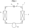
- the refrigerant circuit (1a) includes a compressor unit (10), a radiator (3), a decompression mechanism (4), and an evaporator (5).
- the decompression mechanism (4) is, for example, an expansion valve.
- the refrigerant circuit (1a) performs a vapor compression refrigeration cycle.
- the refrigerant compressed by the compressor unit (10) dissipates heat to the air in the radiator (3).
- the refrigerant which has dissipated heat is decompressed by the decompression mechanism (4) and evaporates in the evaporator (5).
- the evaporated refrigerant is sucked into the compressor unit (10).
- the refrigeration apparatus (1) is an air conditioner.
- the air conditioner may be any of a cooling-only apparatus, a heating-only apparatus, or an air conditioner switchable between cooling and heating.
- the air conditioner has a switching mechanism (e.g., a four-way switching valve) configured to switch the direction of circulation of the refrigerant.
- the refrigeration apparatus (1) may be a water heater, a chiller unit, or a cooling apparatus configured to cool air in an internal space.
- the cooling apparatus cools the air in an internal space of a refrigerator, a freezer, a container, or the like.
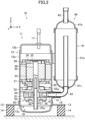
- the compressor unit (10) includes a compressor body (11) and an accumulator (40).
- the accumulator (40) is connected to the compressor body (11).
- the compressor body (11) includes a casing (12), a drive mechanism (20), and a compression mechanism (50).
- the lateral direction in which the compressor body (11) and the accumulator (40) are arranged will be referred to as the "X-axis direction,” the depth direction of the sheet orthogonal to the X-axis direction as the “Y-axis direction,” and the vertical direction along which the compressor body (11) stands as the "Z-axis direction.”
- the casing (12) is configured as a vertically long cylindrical closed container.
- the casing (12) includes a barrel (12a), an upper cup (12b), and a lower cup (12c).
- the barrel (12a) is in the shape of a cylinder extending in the vertical direction, with both axial ends open.
- the upper cup (12b) is fixed to the upper end of the barrel (12a) to close the upper opening of the barrel (12a).
- the lower cup (12c) is fixed to the lower end of the barrel (12a) to close the lower opening of the barrel (12a).
- a suction pipe (16) passes through, and is fixed to, the barrel (12a).
- a discharge pipe (17) passes through, and is fixed to, the upper cup (12b).
- the barrel (12a) of the casing (12) is provided with a plurality of support legs (13) spaced apart from one another in the circumferential direction.
- a vibration isolating member (14) is provided below each support leg (13).
- the vibration isolating member (14) is made of, for example, a rubber material.
- the casing (12) is supported by the vibration isolating members (14) via the support legs (13).
- the casing (12) has, at its bottom, an oil reservoir (18).
- the oil reservoir (18) is formed by the inner wall of a lower portion of the barrel (12a) and the lower cup (12c).
- the oil reservoir (18) stores a lubricant.
- the lubricant lubricates sliding portions of the compression mechanism (50) and a drive shaft (25).
- the drive mechanism (20) is housed in the casing (12).
- the drive mechanism (20) includes a motor (21), the drive shaft (25), and balance weights (30).
- the motor (21) is disposed above the compression mechanism (50).
- the motor (21) includes a stator (22) and a rotor (23).
- the balance weights (30) are provided at both axial ends of the rotor (23).
- the stator (22) is fixed to the inner peripheral surface of the barrel (12a) of the casing (12).
- the rotor (23) passes through the stator (22) in the vertical direction.
- the drive shaft (25) is placed in the axis of the rotor (23) and fixed thereto. The drive shaft (25) is driven to rotate together with the rotor (23) when the motor (21) is energized.
- the drive shaft (25) is located on the axis of the barrel (12a) of the casing (12).
- An oil supply passage (25a) is formed inside the drive shaft (25).
- the lower end of the drive shaft (25) is immersed in the oil reservoir (18).
- the lubricant stored in the oil reservoir (18) is supplied to the sliding portions of the compression mechanism (50) and the drive shaft (25) through the oil supply passage (25a) inside the drive shaft (25).
- the drive shaft (25) has a main shaft portion (26) and an eccentric portion (27).
- An upper portion of the main shaft portion (26) is fixed to the rotor (23) of the motor (21).
- the eccentric portion (27) has an axis decentered by a predetermined distance with respect to the axis of the main shaft portion (26).
- a portion of the main shaft portion (26) above the eccentric portion (27) is rotatably supported by a boss portion (52b) of a front head (52) to be described later.
- a portion of the main shaft portion (26) below the eccentric portion (27) is rotatably supported by a rear head (53) to be described later.
- the compression mechanism (50) is housed in the casing (12).
- the compression mechanism (50) is disposed below the motor (21).
- the compression mechanism (50) includes a cylinder (51), the front head (52), the rear head (53), a piston (54), and a blade (57).
- the cylinder (51) is configured as a flat and substantially annular member.
- the cylinder (51) has a circular compression chamber (55) at its center.
- the cylinder (51) has a suction passage (56) extending in a radial direction.
- the downstream end of the suction passage (56) communicates with the compression chamber (55).
- the suction pipe (16) is connected to the upstream end of the suction passage (56).
- the barrel (12a) of the casing (12) has a through hole (15) at a position facing the suction passage (56).
- a joint pipe (19) is connected to the through hole (15) of the casing (12).
- the joint pipe (19) is made of a cylindrical member made of a metal material.
- the joint pipe (19) is joined to the barrel (12a) of the casing (12) while being fitted in the through hole (15).
- the joint pipe (19) extends from the barrel (12a) of the casing (12) toward the outside of the casing (12).
- the suction pipe (16) is connected to the suction passage (56) of the cylinder (51) and extends through the inside of the joint pipe (19) to the outside of the casing (12).
- the outer peripheral surface of the suction pipe (16) is brazed to the inner peripheral surface of the joint pipe (19).
- the front head (52) is disposed on an upper portion of the cylinder (51).
- the front head (52) covers the internal space of the cylinder (51) from above.
- the front head (52) includes an annular plate portion (52a) and the boss portion (52b).
- the annular plate portion (52a) is made of a flat annular member and is stacked on an upper end portion of the cylinder (51).
- the annular plate portion (52a) is fixed to the inner peripheral surface of the barrel (12a) of the casing (12).
- the boss portion (52b) is made of a tubular member extending upward from a radially central portion of the annular plate portion (52a).
- the boss portion (52b) rotatably supports the main shaft portion (26) of the drive shaft (25).
- the front head (52) has a discharge passage (not shown) passing through the annular plate portion (52a) in the axial direction.
- the rear head (53) is disposed on a lower portion of the cylinder (51).
- the rear head (53) covers the internal space of the cylinder (51) from below.
- the rear head (53) rotatably supports the main shaft portion (26) of the drive shaft (25).
- the piston (54) is housed in the cylinder (51).
- the blade (57) is integrated with the piston (54).
- the compression chamber (55) is defined by the cylinder (51) and the piston (54).
- the piston (54) has a perfect circular annular shape.
- the eccentric portion (27) of the drive shaft (25) is fitted in the piston (54).
- the interior of the compression chamber (55) is partitioned into a low-pressure chamber (55a) and a high-pressure chamber (55b) by the blade (57).
- the blade (57) is supported by a pair of bushes (58), which allow oscillation of the blade (57).
- the piston (54) rotates eccentrically in the cylinder (51) when the drive shaft (25) is driven to rotate.
- the refrigerant flowing through the suction pipe (16) is sucked into the low-pressure chamber (55a) through the suction passage (56) as the volume of the low-pressure chamber (55a) is gradually increased by the eccentric rotation of the piston (54).
- the low-pressure chamber (55a) is isolated from the suction passage (56), and the isolated space forms the high-pressure chamber (55b).
- the internal pressure of the high-pressure chamber (55b) increases as the volume of the high-pressure chamber (55b) gradually decreases.
- the refrigerant in the high-pressure chamber (55b) flows out of the compression mechanism (50) through a discharge passage (59).
- This high-pressure refrigerant flows upward in the internal space of the casing (12) and passes through core cuts (not shown) or other portions of the motor (21).
- the high-pressure refrigerant that has flowed upward of the motor (21) is transferred to the refrigerant circuit through the discharge pipe (17).
- the accumulator (40) is connected to the upstream side of the compressor body (11).
- the accumulator (40) temporarily stores the refrigerant before suction into the compressor body (11) and provides gas-liquid separation of a liquid refrigerant and refrigerating machine oil which are contained in a refrigerant gas.
- the accumulator (40) includes a container body (41), an inlet pipe (42), and an outlet pipe (43).
- the inlet pipe (42) allows the refrigerant to flow into the container body (41).
- the outlet pipe (43) allows the refrigerant to flow out of the container body (41).
- the container body (41) is configured as a vertically long cylindrical member.
- the container body (41) includes a barrel (41a), an upper housing (41b), and a lower housing (41c).
- the barrel (41a) is in the shape of a cylinder extending in the vertical direction with both axial ends open.
- the upper housing (41b) is fixed to the upper end of the barrel (41a) to close the upper opening of the barrel (41a).
- the lower housing (41c) is fixed to the lower end of the barrel (41a) to close the lower opening of the barrel (41a).
- the inlet pipe (42) is connected to an upper portion of the upper housing (41b). A lower end portion of the inlet pipe (42) is open near an upper portion of the internal space of the container body (41).
- the outlet pipe (43) is connected to a lower portion of the lower housing (41c). An upper end portion of the outlet pipe (43) extends upward in the container body (41) and is open near the upper portion of the internal space of the container body (41).
- a lower end portion of the outlet pipe (43) extends downward from the lower end of the container body (41) and is then bent toward the suction pipe (16) of the compressor body (11) so as to be connected to the suction pipe (16).
- the inventors of this application have focused on the difference in vibration transmissibility characteristics between the 1n frequency that is one time the operation frequency n of the compressor body (11) and the 3n frequency that is three times the operation frequency n of the compressor body (11), as a factor that increases the vibration of the accumulator (40).
- the exciting force at the 1n frequency torque and the centrifugal forces of the piston (54) and the rotor (23) are great.
- torque is great.
- the timing at which the exciting force is transmitted as the accumulator vibration differs depending on the frequencies. In other words, the vibration transmission phase differs between the 1n frequency and the 3n frequency.
- the peak vibrations at the 1n frequency and at the 3n frequency overlap each other, raising the peak-to-peak value of accumulator vibration.
- the optimum phase difference between the 1n frequency and the 3n frequency will be studied so that an increase in the vibration transmitted from the compressor body (11) to the accumulator (40) can be substantially prevented even if the number of revolutions of the compressor body (11) is increased.
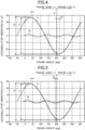
- FIG. 4 is a graph showing the relation between the crank angle and accumulator vibration in a situation where the phase difference is 0°.
- the maximum number of revolutions of the compressor body (11) is equal to or greater than 118 rps, specifically 120 rps.
- the discharge pressure is 3.5 MPa, and the suction pressure is 1.1 MPa.
- the phase lag is positive, and the phase lead is negative.
- the phase of the 3n frequency is at a position that leads the phase of the 1n frequency by about 11° to 19° in advance.
- the peak vibration at the 1n frequency and the peak vibration at the 3n frequency overlap each other.
- the peak-to-peak value v2 of a synthesis of the waveform of the 1n frequency and the waveform of the 3n frequency (the dotted waveform referred to as "sum" in FIG. 4 ) is greater than the peak-to-peak value v1 of the waveform of the 1n frequency, resulting in an increase in the vibrations transmitted from the compressor body (11) to the accumulator (40).
- the peak vibration at the 1n frequency and the peak vibration at the 3n frequency overlap each other.
- the peak-to-peak value v2 of a synthesis of the waveform of the 1n frequency and the waveform of the 3n frequency is greater than the peak-to-peak value v1 of the waveform of the 1n frequency, resulting in an increase in the vibrations transmitted from the compressor body (11) to the accumulator (40).
- the peak vibration at the 1n frequency and the peak vibration at the 3n frequency are shifted from each other.
- the peak-to-peak value v1 of the waveform of the 1n frequency and the peak-to-peak value v2 of a synthesis of the waveform of the 1n frequency and the waveform of the 3n frequency are substantially the same, so that it is possible to substantially prevent an increase in the vibration transmitted from the compressor body (11) to the accumulator (40).
- the peak vibration at the 1n frequency and the peak vibration at the 3n frequency are shifted from each other, and the crest and the trough overlap each other.
- the peak-to-peak value v2 of a synthesis of the waveform of the 1n frequency and the waveform of the 3n frequency is smaller than the peak-to-peak value v1 of the waveform of the 1n frequency, so that it is possible to substantially prevent an increase in the vibration transmitted from the compressor body (11) to the accumulator (40) more.
- the peak vibration at the 1n frequency and the peak vibration at the 3n frequency are shifted from each other.
- the peak-to-peak value v1 of the waveform of the 1n frequency and the peak-to-peak value v2 of a synthesis of the waveform of the 1n frequency and the waveform of the 3n frequency are substantially the same, so that it is possible to substantially prevent an increase in the vibration transmitted from the compressor body (11) to the accumulator (40).
- the peak vibration at the 1n frequency and the peak vibration at the 3n frequency partially overlap each other, as compared to the case when the phase difference is 60°.
- the peak-to-peak value v2 of a synthesis of the waveform of the 1n frequency and the waveform of the 3n frequency is slightly greater than, or substantially equal to, the peak-to-peak value v1 of the waveform of the 1n frequency, which is less effective in substantially preventing an increase in the vibration transmitted from the compressor body (11) to the accumulator (40).
- the peak vibration at the 1n frequency and the peak vibration at the 3n frequency overlap each other.
- the peak-to-peak value v2 of a synthesis of the waveform of the 1n frequency and the waveform of the 3n frequency is greater than the peak-to-peak value v1 of the waveform of the 1n frequency, resulting in an increase in the vibrations transmitted from the compressor body (11) to the accumulator (40).
- the phase difference ⁇ between the phase of the transfer function of the 1n frequency of the accumulator (40) and the phase of the transfer function of the 3n frequency of the accumulator (40) is set to be -20° ⁇ ⁇ ⁇ -60° with respect to the peak of the 1n frequency where the phase lag is positive, at a maximum number of revolutions of the compressor body (11).
- the peak vibration at the 1n frequency and the peak vibration at the 3n frequency are shifted from each other without overlapping each other.
- the peak-to-peak value of the vibration of the accumulator (40) thus becomes smaller, so that it is possible to substantially prevent an increase in the vibration transmitted from the compressor body (11) to the accumulator (40).
- FIG. 11 is a graph showing the relation between the number of revolutions of the compressor body and the peak-to-peak value of the accumulator vibration.
- the present embodiment in which the consideration is given to the phase difference ⁇ between the 1n frequency and the 3n frequency is indicated by the solid line, and a comparative example in which no consideration is given to the phase difference ⁇ between the 1n frequency and the 3n frequency is indicated by the phantom line.
- the exciting force at the 1n frequency is determined such that torque and centrifugal force are equal to each other when the number of revolutions of the compressor body (11) is 100 rps, considering the whirling of the piston (54).
- the transmissibility characteristics of the 1n frequency and the 3n frequency are both assumed to be one.
- the peak-to-peak value of the comparative example is smaller than the peak-to-peak value of this embodiment in a range where the number of revolutions of the compressor body (11) is small.
- the peak-to-peak value of this embodiment is smaller than the peak-to-peak value of the comparative example, when the number of revolutions of the compressor body (11) reaches 118 rps or more.
- the graph of FIG. 11 shows that the vibrations of the accumulator (40) can be reduced more in the compressor unit (10) according to this embodiment than in the comparative example in a high rotational speed range of the piston (54).
- the maximum number of revolutions of the compressor body (11) is set to be equal to or greater than 118 rps.
- the maximum number of revolutions of the compressor body (11) is preferably equal to or greater than 130 rps.
- rubber foot resonance (see FIG. 12 ), shaft resonance (see FIG. 13 ), and accumulator resonance (see FIG. 14 ) are factors that vibrate the accumulator (40).
- the rubber foot resonance refers to the vibration of the accumulator (40) caused by elastic deformation of the rubber material as the vibration isolating member (14).
- the compressor body (11) is inclined leftward, and the accumulator (40) is inclined leftward.
- Resonance design for the resonance frequency of the rubber foot resonance can be achieved by changing the stiffness of the vibration isolating member (14) and the weight of the compressor body (11) as appropriate.
- the shaft resonance refers to the vibration of the accumulator (40) caused by elastic deformation of the drive shaft (25) inside the casing (12) of the compressor body (11).
- the compressor body (11) remains supported by the vibration isolating members (14) and is not inclined, whereas the drive shaft (25) bends leftward inside the casing (12), and the accumulator (40) is inclined rightward.
- Resonance design for the resonance frequency of the shaft resonance can be achieved by changing the stiffness of the drive shaft (25), the weight of the rotor (23), the support stiffness of the accumulator (40), and the weight of the accumulator (40) as appropriate.
- the accumulator resonance refers to the vibration of the accumulator (40) caused by the inclinations of the accumulator (40) and the compressor body (11) in opposite directions.
- the compressor body (11) is inclined rightward
- the accumulator (40) is inclined leftward.
- Resonance design for the resonance frequency of the accumulator resonance can be achieved by changing the weight of the compressor body (11), the support stiffness of the accumulator (40), and the weight of the accumulator (40) as appropriate.
- the phase is advanced by utilizing antiresonance so that the exciting force at the 3n frequency will not be transmitted to the accumulator (40) later than the exciting force at the 1n frequency.
- the antiresonance occurs when the vibrations of the rubber foot resonance and the shaft resonance overlap (see FIG. 15 ) and when the vibrations of the shaft resonance and the accumulator resonance overlap (see FIG. 16 ).
- the compressor body (11) is inclined leftward and the drive shaft (25) is bent leftward inside the casing (12).
- the accumulator (40) is not inclined at this moment, making it possible to reduce vibrations transmitted to the accumulator (40).
- the drive shaft (25) is bent leftward inside the casing (12) and the compressor body (11) is inclined rightward.
- the accumulator (40) is not inclined at this moment, making it possible to reduce vibrations transmitted to the accumulator (40).
- the phase of the 3n frequency at the maximum number of revolutions has a phase lead characteristic that leads the phase of the 1n at the maximum number of revolutions by about 80°.
- the frequency of the rubber foot resonance in which the vibration isolating member (14) resonates is lower than the frequency of the shaft resonance in which the drive shaft (25) resonates.
- the frequency of the antiresonance that occurs when the vibrations of the rubber foot resonance and the shaft resonance overlap is included between the frequency of the rubber foot resonance and the frequency of the shaft resonance.
- the frequency of the shaft resonance in which the drive shaft (25) resonates is lower than the frequency of the accumulator resonance in which the accumulator (40) resonates.
- the frequency of the antiresonance that occurs when the vibrations of the shaft resonance and the accumulator resonance overlap is included between the frequency of the shaft resonance and the frequency of the accumulator resonance.
- the frequency at which the vibration isolating member (14) resonates is referred to as the "first resonance frequency.”
- a lower one of the frequency at which the drive shaft (25) resonates or the frequency at which the accumulator (40) resonates is referred to as the "second resonance frequency.”
- the frequency at which the drive shaft (25) resonates is lower than the frequency at which the accumulator (40) resonates.
- the frequency at which the drive shaft (25) resonates is the second resonance frequency. If the frequency at which the accumulator (40) resonates is lower than the frequency at which the drive shaft (25) resonates, the frequency at which the accumulator (40) resonates is the second resonance frequency.
- the antiresonance frequency at which antiresonance occurs in the accumulator (40) is included between the first resonance frequency and the second resonance frequency.
- the frequency of the antiresonance that occurs when the vibrations of the rubber foot resonance and the shaft resonance overlap is the antiresonance frequency.
- the 1n frequency is set to be equal to or higher than the first resonance frequency and equal to or lower than the antiresonance frequency at the maximum number of revolutions of the compressor body (11).
- the 3n frequency is set to be equal to or higher than the antiresonance frequency at the maximum number of revolutions of the compressor body (11).
- the phase can be advanced by utilizing antiresonance so that the exciting force at the 3n frequency resulting from the rotation of the piston will not be transmitted to the accumulator (40) later than the exciting force at the 1n frequency.
- the refrigeration apparatus (1) is a cooling-only apparatus, and the rated capacity P [kW] of the refrigeration apparatus (1) and the volume V [cc] of the cylinder (51) satisfy the condition P/V ⁇ 1.9.
- the refrigeration apparatus (1) may be a cooling and heating machine configured to switch between cooling and heating.
- the rated capacity P [kW] of the refrigeration apparatus (1) during a cooling operation and the volume V [cc] of the cylinder (51) need to satisfy the condition P/V ⁇ 2.6.
- a frequency that is one time the operation frequency n of the compressor body (11) and a frequency that is three times the operation frequency n of the compressor body (11) are referred to as the 1n frequency and the 3n frequency, respectively.
- the phase difference ⁇ between the phase of the transfer function of the 1n frequency of the accumulator (40) and the phase of the transfer function of the 3n frequency of the accumulator (40) is set to be -20° ⁇ ⁇ ⁇ -60° with respect to the peak of the 1n frequency where the phase lag is positive, at a maximum number of revolutions of the compressor body (11).
- the peak vibration at the 1n frequency and the peak vibration at the 3n frequency are shifted from each other without overlapping each other.
- the peak-to-peak value of the vibration of the accumulator (40) thus becomes smaller, so that it is possible to substantially prevent an increase in the vibration transmitted from the compressor body (11) to the accumulator (40).
- the frequency at which the vibration isolating member (14) resonates is referred to as the first resonance frequency
- a lower one of the frequency at which the drive shaft (25) resonates or the frequency at which the accumulator (40) resonates is referred to as the second resonance frequency.
- the antiresonance frequency at which antiresonance occurs in the accumulator (40) is included between the first resonance frequency and the second resonance frequency.
- the 1n frequency is set to be equal to or higher than the first resonance frequency and equal to or lower than the antiresonance frequency at the maximum number of revolutions of the compressor body (11), and the 3n frequency is set to be equal to or higher than the antiresonance frequency at the maximum number of revolutions of the compressor body (11).
- the phase can be advanced by utilizing antiresonance so that the exciting force at the 3n frequency resulting from the rotation of the piston (54) will not be transmitted to the accumulator (40) later than the exciting force at the 1n frequency.
- the compressor performance it is possible to improve the compressor performance and keep the vibrations of the accumulator (40) from increasing in a high rotational speed range as well, by increasing the maximum number of revolutions of the compressor body (11) to 118 rps or more.
- the maximum number of revolutions of the compressor body (11) is preferably equal to or greater than 130 rps.
- a refrigeration apparatus includes the compressor unit (10) and the refrigerant circuit (1a) through which the refrigerant compressed by the compressor unit (10) flows. It is therefore possible to provide the refrigeration apparatus including the compressor unit (10).
- the refrigeration apparatus (1) is a cooling-only apparatus, and the rated capacity P [kW] of the refrigeration apparatus (1) and the volume V [cc] of the cylinder (51) satisfy the condition P/V ⁇ 1.9. It is thus possible to reduce the volume of the cylinder (51) per unit capacity in providing the compressor body (11) smaller in size and higher in speed.
- the refrigeration apparatus (1) is a cooling and heating machine configured to switch between cooling and heating, and the rated capacity P [kW] of the refrigeration apparatus (1) during the cooling operation and the volume V [cc] of the cylinder (51) satisfy the condition P/V ⁇ 2.6. It is thus possible to reduce the volume of the cylinder (51) per unit capacity in providing the compressor body (11) smaller in size and higher in speed.
- an oscillating piston compressor including the piston (54) and the blade (57) integrated together has been described.
- a rolling piston rotary compressor including the piston (54) and the blade (57) separate from each other may be used.
- the present disclosure is useful for a compressor unit and a refrigeration apparatus.
Landscapes
- Engineering & Computer Science (AREA)
- Mechanical Engineering (AREA)
- General Engineering & Computer Science (AREA)
- Applications Or Details Of Rotary Compressors (AREA)
- Compressor (AREA)
- Physics & Mathematics (AREA)
- Thermal Sciences (AREA)
- Fluid Mechanics (AREA)
Abstract
Description
- The present disclosure relates to a compressor unit and a refrigeration apparatus.
-
Patent Document 1 discloses a vertical compressor configured to reduce vibrations transmitted to an accumulator through adjustment of the position of a bracket to which the accumulator is attached, such that the natural frequency of the accumulator is higher than the operation frequency of the compressor during operation of the compressor. - Patent Document 1:
Japanese Unexamined Patent Publication No. 2001-317479 - As factors that increase the accumulator vibration, the inventors of this application have focused not only on the resonance of the accumulator, but also on the difference in vibration transmissibility characteristics between a frequency that is one time the operation frequency (1n frequency) of a compressor body and a frequency that is three times the operation frequency (3n frequency) of the compressor body.
- Specifically, the inventors of this application have found a phenomenon in which the peak vibrations at the 1n frequency and the 3n frequency overlap each other, raising the peak-to-peak value of the accumulator vibration. However, according to the invention of
Patent Document 1, no consideration is given to the difference in vibration transmissibility characteristics between the 1n frequency and the 3n frequency. - It is an object of the present disclosure to substantially prevent an increase in the vibration transmitted from a compressor body to an accumulator.
- A first aspect of the present disclosure is directed to a compressor unit including: a compressor body (11) including a compression mechanism (50); and an accumulator (40) connected to the compressor body (11), the compression mechanism (50) including: a cylinder (51); a piston (54) configured to rotate eccentrically in the cylinder (51); and a blade (57) partitioning an interior of a compression chamber (55) of the cylinder (51) into a low-pressure chamber (55a) and a high-pressure chamber (55b), a frequency that is one time an operation frequency n of the compressor body (11) and a frequency that is three times the operation frequency n of the compressor body (11) being referred to as a 1n frequency and a 3n frequency, respectively, a phase difference θ between a phase of a transfer function of the 1n frequency of the accumulator (40) and a phase of a transfer function of the 3n frequency of the accumulator (40) being set to be -20° ≥ θ ≥ -60° with respect to a peak of the 1n frequency where the phase lag is positive, at a maximum number of revolutions of the compressor body (11).
- According to the first aspect, the phase difference θ between the phase of the transfer function of the 1n frequency of the accumulator (40) and the phase of the transfer function of the 3n frequency of the accumulator (40) is set to be -20° ≥ θ ≥ -60° at a maximum number of revolutions of the compressor body (11).
- The phase difference θ is -60° ≥ 30 ≥ -180° with respect to a peak of the 3n frequency, and the phase of the transfer function of the 3n frequency of the accumulator (40) needs to lead the phase of the transfer function of the 1n frequency of the accumulator (40) by 60° to 180° at the maximum number of revolutions of the compressor body (11).
- By this setting, the peak vibration at the 1n frequency and the peak vibration at the 3n frequency are shifted from each other without overlapping each other. The peak-to-peak value of the vibration of the accumulator (40) thus becomes smaller, so that it is possible to substantially prevent an increase in the vibration transmitted from the compressor body (11) to the accumulator (40).
- A second aspect of the present disclosure is the compressor unit of the first aspect. The compressor unit of the second aspect further includes: a drive mechanism (20) configured to drive the compression mechanism (50), wherein the drive mechanism (20) includes a drive shaft (25) and a motor (21) configured to rotate the drive shaft (25), the compressor body (11) includes a casing (12) and a vibration isolating member (14) configured to support the casing (12), a frequency at which the vibration isolating member (14) resonates is referred to as a first resonance frequency, a lower one of a frequency at which the drive shaft (25) resonates or a frequency at which the accumulator (40) resonates is referred to as a second resonance frequency, an antiresonance frequency at which antiresonance occurs in the accumulator (40) is included between the first resonance frequency and the second resonance frequency, and the 1n frequency is set to be equal to or higher than the first resonance frequency and equal to or lower than the antiresonance frequency at the maximum number of revolutions of the compressor body (11), and the 3n frequency is set to be equal to or higher than the antiresonance frequency at the maximum number of revolutions of the compressor body (11).
- According to the second aspect, the 1n frequency is set to be equal to or higher than the first resonance frequency and equal to or lower than the antiresonance frequency at the maximum number of revolutions of the compressor body (11), and the 3n frequency is set to be equal to or higher than the antiresonance frequency at the maximum number of revolutions of the compressor body (11).
- Thus, the phase can be advanced by utilizing antiresonance so that the exciting force at the 3n frequency resulting from the rotation of the piston (54) will not be transmitted to the accumulator (40) later than the exciting force at the 1n frequency.
- A third aspect of the present disclosure is the compressor unit of the first or second aspect. In the third aspect, the maximum number of revolutions of the compressor body (11) is equal to or higher than 118 rps.
- According to the third aspect, it is possible to improve the compressor performance and keep the vibrations of the accumulator (40) from increasing in a high rotational speed range as well, by increasing the maximum number of revolutions of the compressor body (11).
- A fourth aspect of the present disclosure is the compressor unit of any one of the first to third aspects. In the fourth aspect, the compressor body (11) is a one-cylinder compressor including the single cylinder (51).
- According to the fourth aspect, it is possible to keep the vibrations of the accumulator (40) from increasing in the case of a one-cylinder compressor body (11) as well, in which a problem of vibrations is particularly significant in a high rotational speed range.
- A fifth aspect of the present disclosure is directed to a refrigeration apparatus. The refrigeration apparatus includes: the compressor unit (10) of any one of the first to fourth aspects; and a refrigerant circuit (1a) through which a refrigerant compressed by the compressor unit (10) flows.
- According to the fifth aspect, it is possible to provide the refrigeration apparatus including the compressor unit (10).
- A sixth aspect of the present disclosure is the refrigeration apparatus of the fifth aspect. In the sixth aspect, the refrigeration apparatus (1) is a cooling-only apparatus, and a rated capacity P [kW] of the refrigeration apparatus (1) and a volume V [cc] of the cylinder (51) satisfy the following condition: P/V < 1.9
- According to the sixth aspect, it is possible to reduce the volume of the cylinder (51) per unit capacity in providing the compressor body (11) smaller in size and higher in speed.
- A seventh aspect of the present disclosure is the refrigeration apparatus of the fifth aspect. In the seventh aspect, the refrigeration apparatus (1) is a cooling and heating machine configured to switch between cooling and heating, and a rated capacity P [kW] of the refrigeration apparatus (1) during a cooling operation and a volume V [cc] of the cylinder (51) satisfy the following condition: P/V < 2.6
- According to the seventh aspect, it is possible to reduce the volume of the cylinder (51) per unit capacity in providing the compressor body (11) smaller in size and higher in speed.
-
-
FIG. 1 is a refrigerant circuit diagram showing a configuration of a refrigeration apparatus according to an embodiment. -
FIG. 2 is a longitudinal sectional view illustrating a configuration of a compressor unit. -
FIG. 3 is a plan sectional view illustrating a configuration of a compression mechanism. -
FIG. 4 is a graph showing the relation between the crank angle and accumulator vibration in a situation where the phase difference is 0°. -
FIG. 5 is a graph showing the relation between the crank angle and accumulator vibration in a situation where the phase difference is 10°. -
FIG. 6 is a graph showing the relation between the crank angle and accumulator vibration in a situation where the phase difference is 20°. -
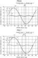
FIG. 7 is a graph showing the relation between the crank angle and accumulator vibration in a situation where the phase difference is 40°. -
FIG. 8 is a graph showing the relation between the crank angle and accumulator vibration in a situation where the phase difference is 60°. -
FIG. 9 is a graph showing the relation between the crank angle and accumulator vibration in a situation where the phase difference is 70°. -
FIG. 10 is a graph showing the relation between the crank angle and accumulator vibration in a situation where the phase difference is 80°. -
FIG. 11 is a graph showing the relation between the number of revolutions of a compressor body and the peak-to-peak value of accumulator vibration. -
FIG. 12 is a diagram illustrating rubber foot resonance. -
FIG. 13 is a diagram illustrating shaft resonance. -
FIG. 14 is a diagram illustrating accumulator resonance. -
FIG. 15 is a diagram illustrating antiresonance that occurs when vibrations of rubber foot resonance and shaft resonance overlap. -
FIG. 16 is a diagram illustrating antiresonance that occurs when vibrations of shaft resonance and accumulator resonance overlap. -
FIG. 17 illustrates graphs of the operation frequency of the compressor body and the transfer functions of the amplitude and phase of the accumulator. - As illustrated in
FIG. 1 , a compressor unit (10) is provided in a refrigeration apparatus (1). The refrigeration apparatus (1) includes a refrigerant circuit (1a) filled with a refrigerant. The refrigerant circuit (1a) includes a compressor unit (10), a radiator (3), a decompression mechanism (4), and an evaporator (5). The decompression mechanism (4) is, for example, an expansion valve. The refrigerant circuit (1a) performs a vapor compression refrigeration cycle. - In the refrigeration cycle, the refrigerant compressed by the compressor unit (10) dissipates heat to the air in the radiator (3). The refrigerant which has dissipated heat is decompressed by the decompression mechanism (4) and evaporates in the evaporator (5). The evaporated refrigerant is sucked into the compressor unit (10).
- The refrigeration apparatus (1) is an air conditioner. The air conditioner may be any of a cooling-only apparatus, a heating-only apparatus, or an air conditioner switchable between cooling and heating. In this case, the air conditioner has a switching mechanism (e.g., a four-way switching valve) configured to switch the direction of circulation of the refrigerant. The refrigeration apparatus (1) may be a water heater, a chiller unit, or a cooling apparatus configured to cool air in an internal space. The cooling apparatus cools the air in an internal space of a refrigerator, a freezer, a container, or the like.
- As illustrated in
FIG. 2 , the compressor unit (10) includes a compressor body (11) and an accumulator (40). The accumulator (40) is connected to the compressor body (11). The compressor body (11) includes a casing (12), a drive mechanism (20), and a compression mechanism (50). - In
FIG. 2 , the lateral direction in which the compressor body (11) and the accumulator (40) are arranged will be referred to as the "X-axis direction," the depth direction of the sheet orthogonal to the X-axis direction as the "Y-axis direction," and the vertical direction along which the compressor body (11) stands as the "Z-axis direction." - The casing (12) is configured as a vertically long cylindrical closed container. The casing (12) includes a barrel (12a), an upper cup (12b), and a lower cup (12c). The barrel (12a) is in the shape of a cylinder extending in the vertical direction, with both axial ends open. The upper cup (12b) is fixed to the upper end of the barrel (12a) to close the upper opening of the barrel (12a). The lower cup (12c) is fixed to the lower end of the barrel (12a) to close the lower opening of the barrel (12a). A suction pipe (16) passes through, and is fixed to, the barrel (12a). A discharge pipe (17) passes through, and is fixed to, the upper cup (12b).
- The barrel (12a) of the casing (12) is provided with a plurality of support legs (13) spaced apart from one another in the circumferential direction. A vibration isolating member (14) is provided below each support leg (13). The vibration isolating member (14) is made of, for example, a rubber material. The casing (12) is supported by the vibration isolating members (14) via the support legs (13).
- The casing (12) has, at its bottom, an oil reservoir (18). The oil reservoir (18) is formed by the inner wall of a lower portion of the barrel (12a) and the lower cup (12c). The oil reservoir (18) stores a lubricant. The lubricant lubricates sliding portions of the compression mechanism (50) and a drive shaft (25).
- The drive mechanism (20) is housed in the casing (12). The drive mechanism (20) includes a motor (21), the drive shaft (25), and balance weights (30). The motor (21) is disposed above the compression mechanism (50). The motor (21) includes a stator (22) and a rotor (23). The balance weights (30) are provided at both axial ends of the rotor (23).
- The stator (22) is fixed to the inner peripheral surface of the barrel (12a) of the casing (12). The rotor (23) passes through the stator (22) in the vertical direction. The drive shaft (25) is placed in the axis of the rotor (23) and fixed thereto. The drive shaft (25) is driven to rotate together with the rotor (23) when the motor (21) is energized.
- The drive shaft (25) is located on the axis of the barrel (12a) of the casing (12). An oil supply passage (25a) is formed inside the drive shaft (25). The lower end of the drive shaft (25) is immersed in the oil reservoir (18). The lubricant stored in the oil reservoir (18) is supplied to the sliding portions of the compression mechanism (50) and the drive shaft (25) through the oil supply passage (25a) inside the drive shaft (25).
- The drive shaft (25) has a main shaft portion (26) and an eccentric portion (27). An upper portion of the main shaft portion (26) is fixed to the rotor (23) of the motor (21). The eccentric portion (27) has an axis decentered by a predetermined distance with respect to the axis of the main shaft portion (26).
- A portion of the main shaft portion (26) above the eccentric portion (27) is rotatably supported by a boss portion (52b) of a front head (52) to be described later. A portion of the main shaft portion (26) below the eccentric portion (27) is rotatably supported by a rear head (53) to be described later.
- The compression mechanism (50) is housed in the casing (12). The compression mechanism (50) is disposed below the motor (21). The compression mechanism (50) includes a cylinder (51), the front head (52), the rear head (53), a piston (54), and a blade (57).
- The cylinder (51) is configured as a flat and substantially annular member. The cylinder (51) has a circular compression chamber (55) at its center. The cylinder (51) has a suction passage (56) extending in a radial direction. The downstream end of the suction passage (56) communicates with the compression chamber (55). The suction pipe (16) is connected to the upstream end of the suction passage (56).
- The barrel (12a) of the casing (12) has a through hole (15) at a position facing the suction passage (56). A joint pipe (19) is connected to the through hole (15) of the casing (12). The joint pipe (19) is made of a cylindrical member made of a metal material. The joint pipe (19) is joined to the barrel (12a) of the casing (12) while being fitted in the through hole (15). The joint pipe (19) extends from the barrel (12a) of the casing (12) toward the outside of the casing (12).
- The suction pipe (16) is connected to the suction passage (56) of the cylinder (51) and extends through the inside of the joint pipe (19) to the outside of the casing (12). The outer peripheral surface of the suction pipe (16) is brazed to the inner peripheral surface of the joint pipe (19).
- The front head (52) is disposed on an upper portion of the cylinder (51). The front head (52) covers the internal space of the cylinder (51) from above. The front head (52) includes an annular plate portion (52a) and the boss portion (52b).
- The annular plate portion (52a) is made of a flat annular member and is stacked on an upper end portion of the cylinder (51). The annular plate portion (52a) is fixed to the inner peripheral surface of the barrel (12a) of the casing (12). The boss portion (52b) is made of a tubular member extending upward from a radially central portion of the annular plate portion (52a). The boss portion (52b) rotatably supports the main shaft portion (26) of the drive shaft (25). The front head (52) has a discharge passage (not shown) passing through the annular plate portion (52a) in the axial direction.
- The rear head (53) is disposed on a lower portion of the cylinder (51). The rear head (53) covers the internal space of the cylinder (51) from below. The rear head (53) rotatably supports the main shaft portion (26) of the drive shaft (25).
- As illustrated also in
FIG. 3 , the piston (54) is housed in the cylinder (51). The blade (57) is integrated with the piston (54). The compression chamber (55) is defined by the cylinder (51) and the piston (54). The piston (54) has a perfect circular annular shape. The eccentric portion (27) of the drive shaft (25) is fitted in the piston (54). The interior of the compression chamber (55) is partitioned into a low-pressure chamber (55a) and a high-pressure chamber (55b) by the blade (57). The blade (57) is supported by a pair of bushes (58), which allow oscillation of the blade (57). - The piston (54) rotates eccentrically in the cylinder (51) when the drive shaft (25) is driven to rotate. The refrigerant flowing through the suction pipe (16) is sucked into the low-pressure chamber (55a) through the suction passage (56) as the volume of the low-pressure chamber (55a) is gradually increased by the eccentric rotation of the piston (54).
- Next, the low-pressure chamber (55a) is isolated from the suction passage (56), and the isolated space forms the high-pressure chamber (55b). The internal pressure of the high-pressure chamber (55b) increases as the volume of the high-pressure chamber (55b) gradually decreases. When the internal pressure of the high-pressure chamber (55b) exceeds a predetermined pressure, the refrigerant in the high-pressure chamber (55b) flows out of the compression mechanism (50) through a discharge passage (59). This high-pressure refrigerant flows upward in the internal space of the casing (12) and passes through core cuts (not shown) or other portions of the motor (21). The high-pressure refrigerant that has flowed upward of the motor (21) is transferred to the refrigerant circuit through the discharge pipe (17).
- The accumulator (40) is connected to the upstream side of the compressor body (11). The accumulator (40) temporarily stores the refrigerant before suction into the compressor body (11) and provides gas-liquid separation of a liquid refrigerant and refrigerating machine oil which are contained in a refrigerant gas.
- The accumulator (40) includes a container body (41), an inlet pipe (42), and an outlet pipe (43). The inlet pipe (42) allows the refrigerant to flow into the container body (41). The outlet pipe (43) allows the refrigerant to flow out of the container body (41).
- The container body (41) is configured as a vertically long cylindrical member. The container body (41) includes a barrel (41a), an upper housing (41b), and a lower housing (41c). The barrel (41a) is in the shape of a cylinder extending in the vertical direction with both axial ends open. The upper housing (41b) is fixed to the upper end of the barrel (41a) to close the upper opening of the barrel (41a). The lower housing (41c) is fixed to the lower end of the barrel (41a) to close the lower opening of the barrel (41a).
- The inlet pipe (42) is connected to an upper portion of the upper housing (41b). A lower end portion of the inlet pipe (42) is open near an upper portion of the internal space of the container body (41). The outlet pipe (43) is connected to a lower portion of the lower housing (41c). An upper end portion of the outlet pipe (43) extends upward in the container body (41) and is open near the upper portion of the internal space of the container body (41).
- A lower end portion of the outlet pipe (43) extends downward from the lower end of the container body (41) and is then bent toward the suction pipe (16) of the compressor body (11) so as to be connected to the suction pipe (16).
- There has been a request to increase the number of revolutions of the compressor body (11) to further improve the compressor capacity. Unfortunately, an increase in the number of revolutions of the compressor body (11) increases vibrations transmitted from the compressor body (11) to the accumulator (40), which propagate to an entire outdoor unit via the inlet pipe (42), resulting in higher piping stress and greater noise generated in the product.
- To address this, the inventors of this application have focused on the difference in vibration transmissibility characteristics between the 1n frequency that is one time the operation frequency n of the compressor body (11) and the 3n frequency that is three times the operation frequency n of the compressor body (11), as a factor that increases the vibration of the accumulator (40).
- Specifically, in the exciting force at the 1n frequency, torque and the centrifugal forces of the piston (54) and the rotor (23) are great. In contrast, in the exciting force at the 3n frequency, torque is great. The timing at which the exciting force is transmitted as the accumulator vibration differs depending on the frequencies. In other words, the vibration transmission phase differs between the 1n frequency and the 3n frequency.
- Depending on the phase difference between the 1n frequency and the 3n frequency, the following phenomenon may occur: the peak vibrations at the 1n frequency and at the 3n frequency overlap each other, raising the peak-to-peak value of accumulator vibration.
- To address this, in this embodiment, the optimum phase difference between the 1n frequency and the 3n frequency will be studied so that an increase in the vibration transmitted from the compressor body (11) to the accumulator (40) can be substantially prevented even if the number of revolutions of the compressor body (11) is increased.
-
FIG. 4 is a graph showing the relation between the crank angle and accumulator vibration in a situation where the phase difference is 0°. In the example shown inFIG. 4 , the maximum number of revolutions of the compressor body (11) is equal to or greater than 118 rps, specifically 120 rps. The discharge pressure is 3.5 MPa, and the suction pressure is 1.1 MPa. The phase lag is positive, and the phase lead is negative. - Here, due to the conditions of the discharge temperature and suction temperature of the refrigerant, the phase of the 3n frequency is at a position that leads the phase of the 1n frequency by about 11° to 19° in advance. In the example shown in
FIG. 4 , the position where the phase of the transfer function of the 3n frequency of the accumulator (40) is shifted by 18° to the phase lead side from the phase of the transfer function of the 1n frequency is assumed to be the phase difference θ = 0° with respect to the peak of the 1n frequency. - As shown in
FIG. 4 , when the phase difference θ is 0°, the peak vibration at the 1n frequency and the peak vibration at the 3n frequency overlap each other. Thus, the peak-to-peak value v2 of a synthesis of the waveform of the 1n frequency and the waveform of the 3n frequency (the dotted waveform referred to as "sum" inFIG. 4 ) is greater than the peak-to-peak value v1 of the waveform of the 1n frequency, resulting in an increase in the vibrations transmitted from the compressor body (11) to the accumulator (40). - As shown in
FIG. 5 , when the phase difference is 10°, the peak vibration at the 1n frequency and the peak vibration at the 3n frequency overlap each other. Thus, the peak-to-peak value v2 of a synthesis of the waveform of the 1n frequency and the waveform of the 3n frequency is greater than the peak-to-peak value v1 of the waveform of the 1n frequency, resulting in an increase in the vibrations transmitted from the compressor body (11) to the accumulator (40). - As shown in
FIG. 6 , when the phase difference is 20°, the peak vibration at the 1n frequency and the peak vibration at the 3n frequency are shifted from each other. Thus, the peak-to-peak value v1 of the waveform of the 1n frequency and the peak-to-peak value v2 of a synthesis of the waveform of the 1n frequency and the waveform of the 3n frequency are substantially the same, so that it is possible to substantially prevent an increase in the vibration transmitted from the compressor body (11) to the accumulator (40). - As shown in
FIG. 7 , when the phase difference is 40°, the peak vibration at the 1n frequency and the peak vibration at the 3n frequency are shifted from each other, and the crest and the trough overlap each other. Thus, the peak-to-peak value v2 of a synthesis of the waveform of the 1n frequency and the waveform of the 3n frequency is smaller than the peak-to-peak value v1 of the waveform of the 1n frequency, so that it is possible to substantially prevent an increase in the vibration transmitted from the compressor body (11) to the accumulator (40) more. - As shown in
FIG. 8 , when the phase difference is 60°, the peak vibration at the 1n frequency and the peak vibration at the 3n frequency are shifted from each other. Thus, the peak-to-peak value v1 of the waveform of the 1n frequency and the peak-to-peak value v2 of a synthesis of the waveform of the 1n frequency and the waveform of the 3n frequency are substantially the same, so that it is possible to substantially prevent an increase in the vibration transmitted from the compressor body (11) to the accumulator (40). - As shown in
FIG. 9 , when the phase difference is 70°, the peak vibration at the 1n frequency and the peak vibration at the 3n frequency partially overlap each other, as compared to the case when the phase difference is 60°. Thus, the peak-to-peak value v2 of a synthesis of the waveform of the 1n frequency and the waveform of the 3n frequency is slightly greater than, or substantially equal to, the peak-to-peak value v1 of the waveform of the 1n frequency, which is less effective in substantially preventing an increase in the vibration transmitted from the compressor body (11) to the accumulator (40). - As shown in
FIG. 10 , when the phase difference is 80°, the peak vibration at the 1n frequency and the peak vibration at the 3n frequency overlap each other. Thus, the peak-to-peak value v2 of a synthesis of the waveform of the 1n frequency and the waveform of the 3n frequency is greater than the peak-to-peak value v1 of the waveform of the 1n frequency, resulting in an increase in the vibrations transmitted from the compressor body (11) to the accumulator (40). - According to this embodiment, based on the results of the studies shown in
FIGS. 4 to 10 as described above, the phase difference θ between the phase of the transfer function of the 1n frequency of the accumulator (40) and the phase of the transfer function of the 3n frequency of the accumulator (40) is set to be -20° ≥ θ ≥ -60° with respect to the peak of the 1n frequency where the phase lag is positive, at a maximum number of revolutions of the compressor body (11). - By this setting, the peak vibration at the 1n frequency and the peak vibration at the 3n frequency are shifted from each other without overlapping each other. The peak-to-peak value of the vibration of the accumulator (40) thus becomes smaller, so that it is possible to substantially prevent an increase in the vibration transmitted from the compressor body (11) to the accumulator (40).
-
FIG. 11 is a graph showing the relation between the number of revolutions of the compressor body and the peak-to-peak value of the accumulator vibration. InFIG. 11 , the present embodiment in which the consideration is given to the phase difference θ between the 1n frequency and the 3n frequency is indicated by the solid line, and a comparative example in which no consideration is given to the phase difference θ between the 1n frequency and the 3n frequency is indicated by the phantom line. - In the example shown in
FIG. 11 , the exciting force at the 1n frequency is determined such that torque and centrifugal force are equal to each other when the number of revolutions of the compressor body (11) is 100 rps, considering the whirling of the piston (54). The transmissibility characteristics of the 1n frequency and the 3n frequency are both assumed to be one. Here, the exciting force F_1n at the 1n frequency and the exciting force F_3n at the 3n frequency are expressed by the following formulae, where R represents the maximum number of revolutions of the compressor body (11):


- As shown in
FIG. 11 , the peak-to-peak value of the comparative example is smaller than the peak-to-peak value of this embodiment in a range where the number of revolutions of the compressor body (11) is small. However, the peak-to-peak value of this embodiment is smaller than the peak-to-peak value of the comparative example, when the number of revolutions of the compressor body (11) reaches 118 rps or more. The graph ofFIG. 11 shows that the vibrations of the accumulator (40) can be reduced more in the compressor unit (10) according to this embodiment than in the comparative example in a high rotational speed range of the piston (54). - Accordingly, in this embodiment, the maximum number of revolutions of the compressor body (11) is set to be equal to or greater than 118 rps. The maximum number of revolutions of the compressor body (11) is preferably equal to or greater than 130 rps.
- Next, optimum ranges of the 1n frequency and 3n frequency for setting the phase difference θ to be in the above-described range will be studied. In the following description, vibrations of an upper portion of the accumulator (40) in the Y-axis direction will be studied.
- First, rubber foot resonance (see
FIG. 12 ), shaft resonance (seeFIG. 13 ), and accumulator resonance (seeFIG. 14 ) are factors that vibrate the accumulator (40). - As illustrated in
FIG. 12 , the rubber foot resonance refers to the vibration of the accumulator (40) caused by elastic deformation of the rubber material as the vibration isolating member (14). In the example illustrated inFIG. 12 , the compressor body (11) is inclined leftward, and the accumulator (40) is inclined leftward. Resonance design for the resonance frequency of the rubber foot resonance can be achieved by changing the stiffness of the vibration isolating member (14) and the weight of the compressor body (11) as appropriate. - As illustrated in
FIG. 13 , the shaft resonance refers to the vibration of the accumulator (40) caused by elastic deformation of the drive shaft (25) inside the casing (12) of the compressor body (11). In the example illustrated inFIG. 13 , the compressor body (11) remains supported by the vibration isolating members (14) and is not inclined, whereas the drive shaft (25) bends leftward inside the casing (12), and the accumulator (40) is inclined rightward. Resonance design for the resonance frequency of the shaft resonance can be achieved by changing the stiffness of the drive shaft (25), the weight of the rotor (23), the support stiffness of the accumulator (40), and the weight of the accumulator (40) as appropriate. - As illustrated in
FIG. 14 , the accumulator resonance refers to the vibration of the accumulator (40) caused by the inclinations of the accumulator (40) and the compressor body (11) in opposite directions. In the example illustrated inFIG. 14 , the compressor body (11) is inclined rightward, and the accumulator (40) is inclined leftward. Resonance design for the resonance frequency of the accumulator resonance can be achieved by changing the weight of the compressor body (11), the support stiffness of the accumulator (40), and the weight of the accumulator (40) as appropriate. - In this embodiment, the phase is advanced by utilizing antiresonance so that the exciting force at the 3n frequency will not be transmitted to the accumulator (40) later than the exciting force at the 1n frequency.
- The antiresonance occurs when the vibrations of the rubber foot resonance and the shaft resonance overlap (see
FIG. 15 ) and when the vibrations of the shaft resonance and the accumulator resonance overlap (seeFIG. 16 ). - As illustrated in
FIG. 15 , in the antiresonance that occurs when the vibrations of the rubber foot resonance and the shaft resonance overlap, the compressor body (11) is inclined leftward and the drive shaft (25) is bent leftward inside the casing (12). The accumulator (40) is not inclined at this moment, making it possible to reduce vibrations transmitted to the accumulator (40). - As illustrated in
FIG. 16 , in the antiresonance that occurs when the vibrations of the shaft resonance and the accumulator resonance overlap, the drive shaft (25) is bent leftward inside the casing (12) and the compressor body (11) is inclined rightward. The accumulator (40) is not inclined at this moment, making it possible to reduce vibrations transmitted to the accumulator (40). - As shown in
FIG. 17 , the phase of the 3n frequency at the maximum number of revolutions has a phase lead characteristic that leads the phase of the 1n at the maximum number of revolutions by about 80°. A phase lead of about 80° at the 3n frequency corresponds to about -27° (= -80/3) when viewed with reference to the time-series waveforms shown inFIGS. 4 to 10 . Due to the phase lead characteristic of about 80°, the peak vibrations at the 1n frequency and at the 3n frequency are shifted so as not to overlap each other, thereby lowering the peak-to-peak value of vibration of the accumulator (40). - As shown in
FIG. 17 , the frequency of the rubber foot resonance in which the vibration isolating member (14) resonates is lower than the frequency of the shaft resonance in which the drive shaft (25) resonates. The frequency of the antiresonance that occurs when the vibrations of the rubber foot resonance and the shaft resonance overlap is included between the frequency of the rubber foot resonance and the frequency of the shaft resonance. - In the example shown in
FIG. 17 , the frequency of the shaft resonance in which the drive shaft (25) resonates is lower than the frequency of the accumulator resonance in which the accumulator (40) resonates. The frequency of the antiresonance that occurs when the vibrations of the shaft resonance and the accumulator resonance overlap is included between the frequency of the shaft resonance and the frequency of the accumulator resonance. - In this embodiment, the frequency at which the vibration isolating member (14) resonates is referred to as the "first resonance frequency." A lower one of the frequency at which the drive shaft (25) resonates or the frequency at which the accumulator (40) resonates is referred to as the "second resonance frequency."
- In the example shown in
FIG. 17 , the frequency at which the drive shaft (25) resonates is lower than the frequency at which the accumulator (40) resonates. Thus, the frequency at which the drive shaft (25) resonates is the second resonance frequency. If the frequency at which the accumulator (40) resonates is lower than the frequency at which the drive shaft (25) resonates, the frequency at which the accumulator (40) resonates is the second resonance frequency. - The antiresonance frequency at which antiresonance occurs in the accumulator (40) is included between the first resonance frequency and the second resonance frequency. In the example shown in
FIG. 17 , the frequency of the antiresonance that occurs when the vibrations of the rubber foot resonance and the shaft resonance overlap is the antiresonance frequency. - The 1n frequency is set to be equal to or higher than the first resonance frequency and equal to or lower than the antiresonance frequency at the maximum number of revolutions of the compressor body (11). The 3n frequency is set to be equal to or higher than the antiresonance frequency at the maximum number of revolutions of the compressor body (11).
- Thus, the phase can be advanced by utilizing antiresonance so that the exciting force at the 3n frequency resulting from the rotation of the piston will not be transmitted to the accumulator (40) later than the exciting force at the 1n frequency.
- The refrigeration apparatus (1) according to this embodiment is a cooling-only apparatus, and the rated capacity P [kW] of the refrigeration apparatus (1) and the volume V [cc] of the cylinder (51) satisfy the condition P/V < 1.9.
- It is thus possible to reduce the volume of the cylinder (51) per unit capacity in providing the compressor body (11) smaller in size and higher in speed.
- The refrigeration apparatus (1) may be a cooling and heating machine configured to switch between cooling and heating. In this case, the rated capacity P [kW] of the refrigeration apparatus (1) during a cooling operation and the volume V [cc] of the cylinder (51) need to satisfy the condition P/V < 2.6.
- According to a feature of this embodiment, a frequency that is one time the operation frequency n of the compressor body (11) and a frequency that is three times the operation frequency n of the compressor body (11) are referred to as the 1n frequency and the 3n frequency, respectively. The phase difference θ between the phase of the transfer function of the 1n frequency of the accumulator (40) and the phase of the transfer function of the 3n frequency of the accumulator (40) is set to be -20° ≥ θ ≥ -60° with respect to the peak of the 1n frequency where the phase lag is positive, at a maximum number of revolutions of the compressor body (11).
- By this setting, the peak vibration at the 1n frequency and the peak vibration at the 3n frequency are shifted from each other without overlapping each other. The peak-to-peak value of the vibration of the accumulator (40) thus becomes smaller, so that it is possible to substantially prevent an increase in the vibration transmitted from the compressor body (11) to the accumulator (40).
- According to a feature of this embodiment, the frequency at which the vibration isolating member (14) resonates is referred to as the first resonance frequency, and a lower one of the frequency at which the drive shaft (25) resonates or the frequency at which the accumulator (40) resonates is referred to as the second resonance frequency. The antiresonance frequency at which antiresonance occurs in the accumulator (40) is included between the first resonance frequency and the second resonance frequency. The 1n frequency is set to be equal to or higher than the first resonance frequency and equal to or lower than the antiresonance frequency at the maximum number of revolutions of the compressor body (11), and the 3n frequency is set to be equal to or higher than the antiresonance frequency at the maximum number of revolutions of the compressor body (11).
- Thus, the phase can be advanced by utilizing antiresonance so that the exciting force at the 3n frequency resulting from the rotation of the piston (54) will not be transmitted to the accumulator (40) later than the exciting force at the 1n frequency.
- According to a feature of this embodiment, it is possible to improve the compressor performance and keep the vibrations of the accumulator (40) from increasing in a high rotational speed range as well, by increasing the maximum number of revolutions of the compressor body (11) to 118 rps or more. The maximum number of revolutions of the compressor body (11) is preferably equal to or greater than 130 rps.
- According to a feature of this embodiment, it is possible to keep the vibrations of the accumulator (40) from increasing in the case of a one-cylinder compressor body (11) as well, in which a problem of vibrations is particularly significant in a high rotational speed range.
- According to a feature of this embodiment, a refrigeration apparatus includes the compressor unit (10) and the refrigerant circuit (1a) through which the refrigerant compressed by the compressor unit (10) flows. It is therefore possible to provide the refrigeration apparatus including the compressor unit (10).
- According to a feature of this embodiment, the refrigeration apparatus (1) is a cooling-only apparatus, and the rated capacity P [kW] of the refrigeration apparatus (1) and the volume V [cc] of the cylinder (51) satisfy the condition P/V < 1.9. It is thus possible to reduce the volume of the cylinder (51) per unit capacity in providing the compressor body (11) smaller in size and higher in speed.
- According to a feature of this embodiment, the refrigeration apparatus (1) is a cooling and heating machine configured to switch between cooling and heating, and the rated capacity P [kW] of the refrigeration apparatus (1) during the cooling operation and the volume V [cc] of the cylinder (51) satisfy the condition P/V < 2.6. It is thus possible to reduce the volume of the cylinder (51) per unit capacity in providing the compressor body (11) smaller in size and higher in speed.
- In this embodiment, an oscillating piston compressor including the piston (54) and the blade (57) integrated together has been described. However, a rolling piston rotary compressor including the piston (54) and the blade (57) separate from each other may be used.
- While the embodiments have been described above, it will be understood that various changes in form and details can be made without departing from the spirit and scope of the claims. The embodiments described above may be appropriately combined or modified by replacing the elements thereof, as long as the functions of the subject matters of the present disclosure are not impaired. In addition, the expressions of "first," "second," "third," ... , in the specification and claims are used to distinguish the terms to which these expressions are given, and do not limit the number and order of the terms.
- As can be seen from the foregoing description, the present disclosure is useful for a compressor unit and a refrigeration apparatus.
-
- 1
- Refrigeration Apparatus
- 1a
- Refrigerant Circuit
- 10
- Compressor Unit
- 11
- Compressor Body
- 12
- Casing
- 14
- Vibration Isolating Member
- 20
- Drive Mechanism
- 21
- Motor
- 25
- Drive Shaft
- 40
- Accumulator
- 50
- Compression Mechanism
- 51
- Cylinder
- 54
- Piston
Claims (7)
- A compressor unit comprising: a compressor body (11) including a compression mechanism (50); and an accumulator (40) connected to the compressor body (11),the compression mechanism (50) including: a cylinder (51); a piston (54) configured to rotate eccentrically in the cylinder (51); and a blade (57) partitioning an interior of a compression chamber (55) of the cylinder (51) into a low-pressure chamber (55a) and a high-pressure chamber (55b),a frequency that is one time an operation frequency n of the compressor body (11) and a frequency that is three times the operation frequency n of the compressor body (11) being referred to as a 1n frequency and a 3n frequency, respectively,a phase difference θ between a phase of a transfer function of the 1n frequency of the accumulator (40) and a phase of a transfer function of the 3n frequency of the accumulator (40) being set to be -20° ≥ θ ≥ -60° with respect to a peak of the 1n frequency where the phase lag is positive, at a maximum number of revolutions of the compressor body (11).
- The compressor unit of claim 1 further comprising:a drive mechanism (20) configured to drive the compression mechanism (50), whereinthe drive mechanism (20) includes a drive shaft (25) and a motor (21) configured to rotate the drive shaft (25),the compressor body (11) includes a casing (12) and a vibration isolating member (14) configured to support the casing (12),a frequency at which the vibration isolating member (14) resonates is referred to as a first resonance frequency,a lower one of a frequency at which the drive shaft (25) resonates or a frequency at which the accumulator (40) resonates is referred to as a second resonance frequency,an antiresonance frequency at which antiresonance occurs in the accumulator (40) is included between the first resonance frequency and the second resonance frequency, andthe 1n frequency is set to be equal to or higher than the first resonance frequency and equal to or lower than the antiresonance frequency at the maximum number of revolutions of the compressor body (11), and the 3n frequency is set to be equal to or higher than the antiresonance frequency at the maximum number of revolutions of the compressor body (11).
- The compressor unit of claim 1 or 2, wherein
the maximum number of revolutions of the compressor body (11) is equal to or higher than 118 rps. - The compressor unit of any one of claims 1 to 3, wherein
the compressor body (11) is a one-cylinder compressor including the single cylinder (51). - A refrigeration apparatus comprising:the compressor unit (10) of any one of claims 1 to 4; anda refrigerant circuit (1a) through which a refrigerant compressed by the compressor unit (10) flows.
- The refrigeration apparatus of claim 5, whereinthe refrigeration apparatus (1) is a cooling-only apparatus, anda rated capacity P [kW] of the refrigeration apparatus (1) and a volume V [cc] of the cylinder (51) satisfy the following condition:

- The refrigeration apparatus of claim 5, whereinthe refrigeration apparatus (1) is a cooling and heating machine configured to switch between cooling and heating, anda rated capacity P [kW] of the refrigeration apparatus (1) during a cooling operation and a volume V [cc] of the cylinder (51) satisfy the following condition:

Applications Claiming Priority (2)
| Application Number | Priority Date | Filing Date | Title |
|---|---|---|---|
| JP2021161444A JP7256421B1 (en) | 2021-09-30 | 2021-09-30 | Compressor unit and refrigeration equipment |
| PCT/JP2022/030262 WO2023053725A1 (en) | 2021-09-30 | 2022-08-08 | Compressor unit and refrigeration device |
Publications (2)
| Publication Number | Publication Date |
|---|---|
| EP4390129A1 true EP4390129A1 (en) | 2024-06-26 |
| EP4390129A4 EP4390129A4 (en) | 2025-03-26 |
Family
ID=85782292
Family Applications (1)
| Application Number | Title | Priority Date | Filing Date |
|---|---|---|---|
| EP22875601.1A Pending EP4390129A4 (en) | 2021-09-30 | 2022-08-08 | Compressor unit and refrigeration device |
Country Status (5)
| Country | Link |
|---|---|
| US (1) | US12565891B2 (en) |
| EP (1) | EP4390129A4 (en) |
| JP (1) | JP7256421B1 (en) |
| CN (1) | CN117999412A (en) |
| WO (1) | WO2023053725A1 (en) |
Families Citing this family (4)
| Publication number | Priority date | Publication date | Assignee | Title |
|---|---|---|---|---|
| JP7143496B1 (en) * | 2021-09-30 | 2022-09-28 | ダイキン工業株式会社 | compressor unit |
| CN116624984B (en) * | 2023-05-29 | 2025-12-16 | 天津大学 | Economic and responsive double-objective optimization model predictive control method for ice storage air conditioning system |
| JP2025181232A (en) * | 2024-05-31 | 2025-12-11 | 三菱重工サーマルシステムズ株式会社 | External unit, transport refrigeration machine, and transport refrigeration vehicle |
| JP2026060605A (en) * | 2024-09-27 | 2026-04-08 | ダイキン工業株式会社 | Refrigerant compressors, refrigeration equipment, and air conditioning systems |
Family Cites Families (6)
| Publication number | Priority date | Publication date | Assignee | Title |
|---|---|---|---|---|
| JPH0267473A (en) * | 1988-08-31 | 1990-03-07 | Toshiba Corp | Compressor |
| JP2001317479A (en) | 2000-05-11 | 2001-11-16 | Matsushita Electric Ind Co Ltd | Vertical compressor |
| US7604466B2 (en) * | 2005-01-31 | 2009-10-20 | Tecumseh Products Company | Discharge muffler system for a rotary compressor |
| JP5321551B2 (en) | 2010-08-04 | 2013-10-23 | 株式会社富士通ゼネラル | Rotary compressor |
| JP6645845B2 (en) * | 2016-01-26 | 2020-02-14 | 三菱重工サーマルシステムズ株式会社 | Accumulator and compressor with multiple pipes |
| JP6377104B2 (en) * | 2016-07-15 | 2018-08-22 | 三菱重工業株式会社 | Motor and motor-equipped equipment |
-
2021
- 2021-09-30 JP JP2021161444A patent/JP7256421B1/en active Active
-
2022
- 2022-08-08 EP EP22875601.1A patent/EP4390129A4/en active Pending
- 2022-08-08 WO PCT/JP2022/030262 patent/WO2023053725A1/en not_active Ceased
- 2022-08-08 CN CN202280064420.9A patent/CN117999412A/en active Pending
-
2024
- 2024-03-21 US US18/612,559 patent/US12565891B2/en active Active
Also Published As
| Publication number | Publication date |
|---|---|
| EP4390129A4 (en) | 2025-03-26 |
| JP7256421B1 (en) | 2023-04-12 |
| WO2023053725A1 (en) | 2023-04-06 |
| CN117999412A (en) | 2024-05-07 |
| US12565891B2 (en) | 2026-03-03 |
| JP2023056556A (en) | 2023-04-20 |
| US20240263631A1 (en) | 2024-08-08 |
Similar Documents
| Publication | Publication Date | Title |
|---|---|---|
| US12565891B2 (en) | Compressor unit and refrigeration apparatus with reduced vibrations | |
| US12448971B2 (en) | Compact low noise rotary compressor | |
| US9828997B2 (en) | Scroll compressor with a resonator | |
| US9748815B2 (en) | Rotary compressor with the balance weight formed with a recess for receiving the head of a rivet | |
| US12429055B2 (en) | Compressor unit | |
| CN110662902B (en) | Hermetic refrigeration compressors and refrigeration units | |
| WO2023170869A1 (en) | Compressor and refrigeration cycle device | |
| JP2018105229A (en) | Variable inertia and rotary compressor | |
| KR101718037B1 (en) | Enclosed compressor | |
| JP6057535B2 (en) | Refrigerant compressor | |
| EP4390133A1 (en) | Compressor unit and refrigeration device | |
| JP7288237B1 (en) | Compressors and refrigeration equipment | |
| JP6841272B2 (en) | Rotary compressor | |
| US20250347278A1 (en) | Rotary compressor and refrigeration apparatus including the same | |
| WO2026069827A1 (en) | Refrigerant compressor, refrigeration device, and air-conditioning system | |
| EP4729783A1 (en) | Rotary compressor and refrigeration apparatus | |
| JP2026020868A (en) | Compressor Unit | |
| WO2022145048A1 (en) | Compressor and refrigeration cycle device using same |
Legal Events
| Date | Code | Title | Description |
|---|---|---|---|
| STAA | Information on the status of an ep patent application or granted ep patent |
Free format text: STATUS: THE INTERNATIONAL PUBLICATION HAS BEEN MADE |
|
| PUAI | Public reference made under article 153(3) epc to a published international application that has entered the european phase |
Free format text: ORIGINAL CODE: 0009012 |
|
| STAA | Information on the status of an ep patent application or granted ep patent |
Free format text: STATUS: REQUEST FOR EXAMINATION WAS MADE |
|
| 17P | Request for examination filed |
Effective date: 20240318 |
|
| AK | Designated contracting states |
Kind code of ref document: A1 Designated state(s): AL AT BE BG CH CY CZ DE DK EE ES FI FR GB GR HR HU IE IS IT LI LT LU LV MC MK MT NL NO PL PT RO RS SE SI SK SM TR |
|
| DAV | Request for validation of the european patent (deleted) | ||
| DAX | Request for extension of the european patent (deleted) | ||
| P01 | Opt-out of the competence of the unified patent court (upc) registered |
Free format text: CASE NUMBER: APP_1098/2025 Effective date: 20250108 |
|
| A4 | Supplementary search report drawn up and despatched |
Effective date: 20250226 |
|
| RIC1 | Information provided on ipc code assigned before grant |
Ipc: F04C 18/356 20060101ALI20250220BHEP Ipc: F04C 23/00 20060101ALI20250220BHEP Ipc: F04C 29/06 20060101ALI20250220BHEP Ipc: F04B 39/00 20060101AFI20250220BHEP |
|
| STAA | Information on the status of an ep patent application or granted ep patent |
Free format text: STATUS: EXAMINATION IS IN PROGRESS |
|
| 17Q | First examination report despatched |
Effective date: 20260220 |