EP4390023A1 - Hinge and opening and closing device - Google Patents
Hinge and opening and closing device Download PDFInfo
- Publication number
- EP4390023A1 EP4390023A1 EP23203663.2A EP23203663A EP4390023A1 EP 4390023 A1 EP4390023 A1 EP 4390023A1 EP 23203663 A EP23203663 A EP 23203663A EP 4390023 A1 EP4390023 A1 EP 4390023A1
- Authority
- EP
- European Patent Office
- Prior art keywords
- hinge
- opening
- hinge seat
- lock plate
- matching
- Prior art date
- Legal status (The legal status is an assumption and is not a legal conclusion. Google has not performed a legal analysis and makes no representation as to the accuracy of the status listed.)
- Pending
Links
Images



Classifications
-
- E—FIXED CONSTRUCTIONS
- E05—LOCKS; KEYS; WINDOW OR DOOR FITTINGS; SAFES
- E05F—DEVICES FOR MOVING WINGS INTO OPEN OR CLOSED POSITION; CHECKS FOR WINGS; WING FITTINGS NOT OTHERWISE PROVIDED FOR, CONCERNED WITH THE FUNCTIONING OF THE WING
- E05F1/00—Closers or openers for wings, not otherwise provided for in this subclass
- E05F1/08—Closers or openers for wings, not otherwise provided for in this subclass spring-actuated, e.g. for horizontally sliding wings
- E05F1/10—Closers or openers for wings, not otherwise provided for in this subclass spring-actuated, e.g. for horizontally sliding wings for swinging wings, e.g. counterbalance
- E05F1/12—Mechanisms in the shape of hinges or pivots, operated by springs
- E05F1/1207—Mechanisms in the shape of hinges or pivots, operated by springs with a coil spring parallel with the pivot axis
- E05F1/1223—Mechanisms in the shape of hinges or pivots, operated by springs with a coil spring parallel with the pivot axis with a compression or traction spring
-
- E—FIXED CONSTRUCTIONS
- E05—LOCKS; KEYS; WINDOW OR DOOR FITTINGS; SAFES
- E05D—HINGES OR SUSPENSION DEVICES FOR DOORS, WINDOWS OR WINGS
- E05D3/00—Hinges with pins
- E05D3/02—Hinges with pins with one pin
-
- E—FIXED CONSTRUCTIONS
- E05—LOCKS; KEYS; WINDOW OR DOOR FITTINGS; SAFES
- E05D—HINGES OR SUSPENSION DEVICES FOR DOORS, WINDOWS OR WINGS
- E05D11/00—Additional features or accessories of hinges
- E05D11/06—Devices for limiting the opening movement of hinges
-
- E—FIXED CONSTRUCTIONS
- E05—LOCKS; KEYS; WINDOW OR DOOR FITTINGS; SAFES
- E05D—HINGES OR SUSPENSION DEVICES FOR DOORS, WINDOWS OR WINGS
- E05D5/00—Construction of single parts, e.g. the parts for attachment
- E05D5/02—Parts for attachment, e.g. flaps
-
- E—FIXED CONSTRUCTIONS
- E05—LOCKS; KEYS; WINDOW OR DOOR FITTINGS; SAFES
- E05D—HINGES OR SUSPENSION DEVICES FOR DOORS, WINDOWS OR WINGS
- E05D7/00—Hinges or pivots of special construction
- E05D7/04—Hinges adjustable relative to the wing or the frame
-
- E—FIXED CONSTRUCTIONS
- E05—LOCKS; KEYS; WINDOW OR DOOR FITTINGS; SAFES
- E05F—DEVICES FOR MOVING WINGS INTO OPEN OR CLOSED POSITION; CHECKS FOR WINGS; WING FITTINGS NOT OTHERWISE PROVIDED FOR, CONCERNED WITH THE FUNCTIONING OF THE WING
- E05F3/00—Closers or openers with braking devices, e.g. checks; Construction of pneumatic or liquid braking devices
- E05F3/18—Closers or openers with braking devices, e.g. checks; Construction of pneumatic or liquid braking devices with counteracting springs
-
- E—FIXED CONSTRUCTIONS
- E05—LOCKS; KEYS; WINDOW OR DOOR FITTINGS; SAFES
- E05F—DEVICES FOR MOVING WINGS INTO OPEN OR CLOSED POSITION; CHECKS FOR WINGS; WING FITTINGS NOT OTHERWISE PROVIDED FOR, CONCERNED WITH THE FUNCTIONING OF THE WING
- E05F3/00—Closers or openers with braking devices, e.g. checks; Construction of pneumatic or liquid braking devices
- E05F3/20—Closers or openers with braking devices, e.g. checks; Construction of pneumatic or liquid braking devices in hinges
-
- E—FIXED CONSTRUCTIONS
- E05—LOCKS; KEYS; WINDOW OR DOOR FITTINGS; SAFES
- E05F—DEVICES FOR MOVING WINGS INTO OPEN OR CLOSED POSITION; CHECKS FOR WINGS; WING FITTINGS NOT OTHERWISE PROVIDED FOR, CONCERNED WITH THE FUNCTIONING OF THE WING
- E05F5/00—Braking devices, e.g. checks; Stops; Buffers
- E05F5/06—Buffers or stops limiting opening of swinging wings, e.g. floor or wall stops
- E05F5/08—Buffers or stops limiting opening of swinging wings, e.g. floor or wall stops with springs
-
- F—MECHANICAL ENGINEERING; LIGHTING; HEATING; WEAPONS; BLASTING
- F25—REFRIGERATION OR COOLING; COMBINED HEATING AND REFRIGERATION SYSTEMS; HEAT PUMP SYSTEMS; MANUFACTURE OR STORAGE OF ICE; LIQUEFACTION SOLIDIFICATION OF GASES
- F25D—REFRIGERATORS; COLD ROOMS; ICE-BOXES; COOLING OR FREEZING APPARATUS NOT OTHERWISE PROVIDED FOR
- F25D23/00—General constructional features
- F25D23/02—Doors; Covers
- F25D23/028—Details
-
- E—FIXED CONSTRUCTIONS
- E05—LOCKS; KEYS; WINDOW OR DOOR FITTINGS; SAFES
- E05Y—INDEXING SCHEME ASSOCIATED WITH SUBCLASSES E05D AND E05F, RELATING TO CONSTRUCTION ELEMENTS, ELECTRIC CONTROL, POWER SUPPLY, POWER SIGNAL OR TRANSMISSION, USER INTERFACES, MOUNTING OR COUPLING, DETAILS, ACCESSORIES, AUXILIARY OPERATIONS NOT OTHERWISE PROVIDED FOR, APPLICATION THEREOF
- E05Y2201/00—Constructional elements; Accessories therefor
- E05Y2201/60—Suspension or transmission members; Accessories therefor
- E05Y2201/622—Suspension or transmission members elements
- E05Y2201/638—Cams; Ramps
-
- E—FIXED CONSTRUCTIONS
- E05—LOCKS; KEYS; WINDOW OR DOOR FITTINGS; SAFES
- E05Y—INDEXING SCHEME ASSOCIATED WITH SUBCLASSES E05D AND E05F, RELATING TO CONSTRUCTION ELEMENTS, ELECTRIC CONTROL, POWER SUPPLY, POWER SIGNAL OR TRANSMISSION, USER INTERFACES, MOUNTING OR COUPLING, DETAILS, ACCESSORIES, AUXILIARY OPERATIONS NOT OTHERWISE PROVIDED FOR, APPLICATION THEREOF
- E05Y2201/00—Constructional elements; Accessories therefor
- E05Y2201/60—Suspension or transmission members; Accessories therefor
- E05Y2201/622—Suspension or transmission members elements
- E05Y2201/696—Screw mechanisms
-
- E—FIXED CONSTRUCTIONS
- E05—LOCKS; KEYS; WINDOW OR DOOR FITTINGS; SAFES
- E05Y—INDEXING SCHEME ASSOCIATED WITH SUBCLASSES E05D AND E05F, RELATING TO CONSTRUCTION ELEMENTS, ELECTRIC CONTROL, POWER SUPPLY, POWER SIGNAL OR TRANSMISSION, USER INTERFACES, MOUNTING OR COUPLING, DETAILS, ACCESSORIES, AUXILIARY OPERATIONS NOT OTHERWISE PROVIDED FOR, APPLICATION THEREOF
- E05Y2600/00—Mounting or coupling arrangements for elements provided for in this subclass
- E05Y2600/50—Mounting methods; Positioning
- E05Y2600/56—Positioning, e.g. re-positioning, or pre-mounting
-
- E—FIXED CONSTRUCTIONS
- E05—LOCKS; KEYS; WINDOW OR DOOR FITTINGS; SAFES
- E05Y—INDEXING SCHEME ASSOCIATED WITH SUBCLASSES E05D AND E05F, RELATING TO CONSTRUCTION ELEMENTS, ELECTRIC CONTROL, POWER SUPPLY, POWER SIGNAL OR TRANSMISSION, USER INTERFACES, MOUNTING OR COUPLING, DETAILS, ACCESSORIES, AUXILIARY OPERATIONS NOT OTHERWISE PROVIDED FOR, APPLICATION THEREOF
- E05Y2800/00—Details, accessories and auxiliary operations not otherwise provided for
- E05Y2800/10—Additional functions
- E05Y2800/12—Sealing
-
- E—FIXED CONSTRUCTIONS
- E05—LOCKS; KEYS; WINDOW OR DOOR FITTINGS; SAFES
- E05Y—INDEXING SCHEME ASSOCIATED WITH SUBCLASSES E05D AND E05F, RELATING TO CONSTRUCTION ELEMENTS, ELECTRIC CONTROL, POWER SUPPLY, POWER SIGNAL OR TRANSMISSION, USER INTERFACES, MOUNTING OR COUPLING, DETAILS, ACCESSORIES, AUXILIARY OPERATIONS NOT OTHERWISE PROVIDED FOR, APPLICATION THEREOF
- E05Y2800/00—Details, accessories and auxiliary operations not otherwise provided for
- E05Y2800/26—Form or shape
- E05Y2800/33—Form or shape having protrusions
-
- E—FIXED CONSTRUCTIONS
- E05—LOCKS; KEYS; WINDOW OR DOOR FITTINGS; SAFES
- E05Y—INDEXING SCHEME ASSOCIATED WITH SUBCLASSES E05D AND E05F, RELATING TO CONSTRUCTION ELEMENTS, ELECTRIC CONTROL, POWER SUPPLY, POWER SIGNAL OR TRANSMISSION, USER INTERFACES, MOUNTING OR COUPLING, DETAILS, ACCESSORIES, AUXILIARY OPERATIONS NOT OTHERWISE PROVIDED FOR, APPLICATION THEREOF
- E05Y2800/00—Details, accessories and auxiliary operations not otherwise provided for
- E05Y2800/69—Permanence of use
- E05Y2800/692—Temporary use, e.g. removable tools
-
- E—FIXED CONSTRUCTIONS
- E05—LOCKS; KEYS; WINDOW OR DOOR FITTINGS; SAFES
- E05Y—INDEXING SCHEME ASSOCIATED WITH SUBCLASSES E05D AND E05F, RELATING TO CONSTRUCTION ELEMENTS, ELECTRIC CONTROL, POWER SUPPLY, POWER SIGNAL OR TRANSMISSION, USER INTERFACES, MOUNTING OR COUPLING, DETAILS, ACCESSORIES, AUXILIARY OPERATIONS NOT OTHERWISE PROVIDED FOR, APPLICATION THEREOF
- E05Y2900/00—Application of doors, windows, wings or fittings thereof
- E05Y2900/30—Application of doors, windows, wings or fittings thereof for domestic appliances
- E05Y2900/306—Application of doors, windows, wings or fittings thereof for domestic appliances for freezers
-
- F—MECHANICAL ENGINEERING; LIGHTING; HEATING; WEAPONS; BLASTING
- F25—REFRIGERATION OR COOLING; COMBINED HEATING AND REFRIGERATION SYSTEMS; HEAT PUMP SYSTEMS; MANUFACTURE OR STORAGE OF ICE; LIQUEFACTION SOLIDIFICATION OF GASES
- F25D—REFRIGERATORS; COLD ROOMS; ICE-BOXES; COOLING OR FREEZING APPARATUS NOT OTHERWISE PROVIDED FOR
- F25D2323/00—General constructional features not provided for in other groups of this subclass
- F25D2323/02—Details of doors or covers not otherwise covered
- F25D2323/024—Door hinges
Definitions
- the present application relates to the field of household appliances, in particular to a hinge and an opening and closing device.
- a freezer is a common type of opening and closing device, and it is generally provided with an upward opening door structure.
- a door body of the freezer When a door body of the freezer is opened, it is necessary to overcome the gravity of the door body, which makes it laborious to open the door body.
- the door body of the freezer When the door body of the freezer is closed, the door body may fall fast due to gravity, causing a severe collision between the door body and a cabinet body of the freezer, affecting the user's experience.
- providing an auxiliary structure on a hinge may provide some assistance during a door opening process and alleviate the problem of rapid dropping of the door body due to gravity and inertia during a door closing process.
- the providing of the auxiliary structure makes the hinge structure complex and occupy a large space, resulting in more labor in hinge assembly.
- due to the increase in space occupied by the hinge the size of the entire freezer will increase. When transporting the freezer, the increase in space occupied by the freezer reduces the number of freezers that may be loaded by transport and
- the purpose of the present application is to at least solve the problem of a complex hinge structure and large space occupation.
- the purpose of the present application is achieved through the following solution.
- a hinge according to the embodiments of the present application comprises:
- the hinge may be connected between the cabinet and the door body of an opening and closing device (such as a freezer), to hinge the door body with the cabinet.
- the door body may be connected to the first hinge seat, and the cabinet may be connected to the second hinge seat.
- the thrust generated by the elastic member under the matching of the first curved surface and the second curved surface may cause the first hinge seat and the second hinge seat to have a relative rotational force, i.e., cause the first hinge seat to have a relative rotational torque to the second hinge seat, the thrust applied by the elastic member to the sliding member may assist the opening of the door body through the first curved surface and the second curved surface; during the closing process of the door body, the elastic member forms a force on the hinge that may at least balance a part of gravity of the door body, alleviating the problem of rapid dropping of the door body which causes a severe collision between the door body and the cabinet, and improving the user experience.
- the elastic member and the sliding member are both provided in the first accommodating cavity of the second hinge seat.
- the hinge may convert the thrust of the elastic member along the first direction into a force in the rotation direction of the hinge.
- the hinge has a simple structure and is easy to assemble, reduces the occupied space, increases the number of opening and closing devices that may be loaded on the transport, and reduces the transportation costs of the opening and closing device.
- hinge according to the present application may further comprise the following features.
- At least either the first curved surface or the second curved surface is a helical surface.
- the first curved surface extends along the first direction, and the first matching surface is provided at an end of the first curved surface close to the second matching structure; and the second curved surface extends along the first direction, and the second matching surface is provided at an end of the second curved surface close to the first matching structure.
- both the first matching surface and the second matching surface are perpendicular to the first direction.
- the first hinge seat comprises a first lock plate and a first hinge portion, the first lock plate is integrated with the first hinge portion, and the first matching structure is provided on the first hinge portion.
- the second hinge seat comprises a second lock plate and a second hinge portion, the second lock plate is integrated with the second hinge portion, and the first accommodating cavity is provided with the second hinge portion.
- the first lock plate is provided with a first mounting hole, the first mounting hole is matched with a fixing member to fix the first lock plate on an opening and closing device.
- the second lock plate comprises a first sub-lock plate and a second sub-lock plate, the first sub-lock plate and the second sub-lock plate are provided at intervals, the first sub-lock plate is embedded in a trench of the opening and closing device, and the second sub-lock plate is provided with a second mounting hole, the second mounting hole is matched with a fixing member to connect the second sub-lock plate with the opening and closing device.
- the first hinge portion is provided with a second accommodating cavity
- the second accommodating cavity is provided with a second opening
- the second opening is opposite to and communicates with the first opening
- the first matching structure is provided in the second accommodating cavity
- an end of the first hinge portion provided with the second opening is connected to, in a sealed manner, an end of the second hinge portion provided with the first opening.
- At least one of the first matching surface, the second matching surface, the first curved surface and the second curved surface is provided with an oil storage tank.
- the second hinge portion is provided with a relief hole at an end away from the first opening, the relief hole communicates with the first accommodating cavity; and/or the first hinge portion is provided with a relief hole at an end away from the second opening, the relief hole communicates with the second accommodating cavity.
- a side of the first lock plate close to the second hinge portion is provided with a first stop
- a side of the second sub-lock plate close to the first hinge portion is provided with a second stop
- the first stop is matched with the second stop to limit a maximum angle for rotation between the first hinge seat and the second hinge portion.
- the first hinge seat is provided with a first positioning portion
- the second hinge seat is provided with a second positioning portion
- the second positioning portion is matched with the first positioning portion to position the first hinge seat and the second hinge seat at an initial mounting angle, the first positioning portion is disconnected from the first hinge seat and/or the second positioning portion is disconnected from the second hinge seat.
- an outer circumferential wall of the sliding member is provided with a first guiding structure extending in the first direction
- the second hinge seat is provided with a second guiding structure extending in the first direction
- the first guiding structure is matched with the second guiding structure, so as to relatively fix the sliding member and the second hinge seat in a circumferential direction of the first accommodating cavity, and to move the sliding member along the first direction.
- the first hinge seat, the second hinge seat, and the sliding member are all made of hard plastic parts.
- An opening and closing device comprising:
- the opening and closing device according to the present application comprising the hinge provided in the present application or any embodiment of the present application, has at least an effect of the effects of the hinge provided in the present application or any embodiment of the present application.
- opening and closing device may further have the following features.
- the opening and closing device is a freezer.
- first”, “second”, “third”, etc. may be used in the description to describe a plurality of elements, parts, regions, layers, and/or sections, these elements, parts, regions, layers, and/or sections should not be limited by these terms. These terms may only be used to distinguish an element, part, region, layer, or section from another element, part, region, layer, or section. Unless explicitly indicated in the context, terms such as “first”, “second”, and other numerical terms do not imply order or sequence when used in the description. Therefore, the first element, part, region, layer or section discussed below may be referred to as the second element, part, region, layer or section without departing from the teachings of the exemplary implementation.
- spatial relative relationship terms may be used in the description to describe the relationship between an element or feature shown in the figure and another element or feature.
- the relative relationship terms are, for example, “internal”, “external”, “inside”, “outside”, “below”, “lower”, “above”, “upper”, etc.
- This spatial relative relationship term means to comprise different orientations of devices in use or operation, except for those depicted in the diagram. For example, if the device in the diagram is flipped, the elements described as “below other elements or features” or “under other elements or features” will then be oriented as “above other elements or features" or “on other elements or features". Therefore, the example term “below” may comprise both upper and lower orientations.
- the device may be additionally oriented (rotated by 90 degrees or in other directions) and the spatial relative relationship descriptors used in the description are explained accordingly.
- a side of the door body (generally the rear side) and a side of the cabinet (generally the rear side) are hinged to enable the door body to rotate on the hinged side to open and close.
- Common hinges used for the opening and closing device comprise plain butt hinges and spring-loaded butt hinges.
- the plain butt hinge has a structure in which the upper seat and lower seat are connected by a rotating shaft, and this type of hinge is simple, without a spring to assist, and may occupy small space.
- this type of hinge the door body only relies on the thrust applied by the user when opening, making it laborious to open the door.
- the working manner of the spring-loaded butt hinge is to vertically provide a compressed spring along the rear side wall of the cabinet body, so that the compressed spring may fit with a connecting rod to provide assistance along an opening direction of the door body to the hinge upper seat during the opening process of the door body.
- the spring force acts on the connecting rod of the first hinge seat.
- the spring-loaded butt hinge requires a relatively great spring force, because the torque applied by the spring on the connecting rod is relatively low, in order to ensure the thrust, the spring force needs to be sufficiently great, which requires a greater outer diameter of the spring, usually greater than 15 mm.
- the thickness of the hinge is generally greater than 20 mm after assembly, which takes up a large amount of space and is not conducive to increasing the loading capacity of transport, leading to an increase in transportation costs.
- the hinge is provided in the cabinet. However, for a freezer, this will reduce the thickness of the foam layer corresponding to a position where the hinge is provided, bring a risk of condensation at this position. As the thickness of the cabinet continues to decrease, the risk of condensation increases, which affects the quality of the freezer.
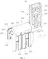
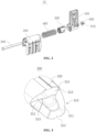
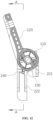
- the hinge 10 comprises a first hinge seat 100, a second hinge seat 200, a sliding member 300, and an elastic member 400.
- the first hinge seat 100 has a first matching structure 140, the first matching structure 140 having a first curved surface 141 and a first matching surface 142.
- the second hinge seat 200 has a first accommodating cavity 230 extending along a first direction X, and an end of the first accommodating cavity 230 has a first opening.
- the sliding member 300 is provided inside the first accommodating cavity 230, and the sliding member 300 and the second hinge seat 200 are fixed opposite in a circumferential direction of the first accommodating cavity 230.
- the sliding member 300 is slidable in the first direction X within the first accommodating cavity 230, and the sliding member 300 has a second matching structure 310, the second matching structure 310 having a second curved surface 311 and a second matching surface 312.
- the second matching structure 310 abuts against the first matching structure 140 through the first opening.
- the elastic member 400 is provided in the first accommodating cavity 230 and is located at an end of the sliding member 300 away from the second matching structure 310. The elastic member 400 applies a thrust to the sliding member 300 to move the sliding member 300 towards the first matching structure 140.
- the hinge 10 has a first state and a second state.
- the first hinge seat 100 is reciprocally rotatable relative to the second hinge seat 200 around an axis extending in the first direction X within a predetermined angle range, causing the first matching structure 140 to slide relative to the second matching structure 310, to make the hinge 10 switch between the first state and the second state.
- the first matching surface 142 abuts against the second matching surface 312, and in the second state, the first curved surface 141 abuts against the second curved surface 311, to make the first hinge seat 100 and the second hinge seat 200 have a force for relative rotation under the thrust.
- the thrust causes the first hinge seat 100 and the second hinge seat 200 to have a force for relative rotation.
- the force applied by the elastic member 400 to the sliding member 300, with the fit of the first curved surface 141 and the second curved surface 311, has a component force that causes the first hinge seat 100 to relatively rotate relative to the second hinge seat 200.
- the first hinge seat 100 and the second hinge seat 200 have a relative rotation trend or rotate under this force.
- the elastic member 400 provides a torque to the first hinge seat 100 and the second hinge seat 200.
- the hinge 10 When the hinge 10 is assembled to the opening and closing device, in generally, in the second state, the hinge 10 has a trend to rotate the door body towards a direction of opening the door body, that is, the hinge 10 has a force to rotate in the first rotation direction, and the first rotation direction is the same as the direction of opening the door body.
- the first curved surface 141 may be a helical surface.
- the second curved surface 311 may also be a helical surface, and both the first curved surface 141 and the second curved surface 311 may extend along the first direction X.
- the first matching surface 142 may be set at an end of the first curved surface 141 close to the second matching structure 310, and the second matching surface 312 may be set at an end of the second curved surface 311 close to the first matching structure 140.
- the first hinge seat 100 may be connected to the door body 30 of the opening and closing device, and the second hinge seat 200 may be connected to the cabinet 20 of the opening and closing device. During the opening or closing process of the door body 30, the second hinge seat 200 is fixed, and the first hinge seat 100 rotates synchronously with the door body 30.
- the first direction X When the hinge 10 is assembled on the opening and closing device, the first direction X may be configured to be parallel to the opening of the opening and closing device. When the opening and closing device is placed on a relatively flat ground, the first direction X may be understood as a horizontal direction. In a case where the opening and closing device has an upward opening door structure, the opening and closing side of the door body 30 is facing forward, and the hinge 10 is provided at the rear side of the opening and closing device, the first direction X may be a left or right direction of the opening and closing device.
- the first state of the hinge 10 may correspond to a closed state of the door body 30 of the opening and closing device and a state with a small opening angle of the door body 30.
- the second state may correspond to a maximum opening state of the door body 30 of the opening and closing device and a state with a large opening angle of the door body 30.
- the first rotation direction is also the opening direction of the door body 30.
- a maximum opening angle of the door body 30 corresponding to the first state may be within a range of 15 degrees to 45 degrees from the closed state towards the opening direction.
- the opening angle of the door body 30 corresponding to the first state is between 0 to 15 degrees, or 0 to 20 degrees, or 0 to 21 degrees, or 0 to 25 degrees, or 0 to 30 degrees, or 0 to 35 degrees, or 0 to 40 degrees, or 0 to 45 degrees, etc.
- the maximum opening angle of the door body 30 corresponding to the first state corresponds to a maximum opening angle where the hinge 10 may not buffer the closing of the door body 30 or assist in the opening of the door body 30.
- the hinge 10 may assist in the opening of the door body 30; before the door body 30 rotates from the maximum open state to the maximum angle of opening corresponding to the first state, the first curved surface 141 abuts against the second curved surface 311, and the hinge 10 may buffer the closing of the door body 30.
- the elastic member 400 may be provided based on the gravity of the door body 30, and the elastic member 400 should make that the torque generated by the hinge 10 in the second state is greater than the torque generated by the gravity of the door body 30, so that the door body 30 may hover in the second state of the hinge 10.
- the opening angle of the door body 30 corresponding to the second state is also a hovering angle of the door body 30.
- the lower limit of the hovering angle range is consistent with the maximum opening angle of the door body 30 corresponding to the first state, that is, the maximum opening angle of the door body 30 corresponding to the first state is a critical point for hovering and non-hovering.
- the door body 30 When the opening angle of the door body 30 is greater than the maximum opening angle of the door body 30 corresponding to the first state, the door body 30 may hover. When the opening angle of the door body 30 is smaller than the maximum opening angle of the door body 30 corresponding to the first state, the door body 30 may not hover.
- the upper limit of the hovering angle range may be consistent with the angle at which the door body 30 opens to the maximum state.
- the preset angle range of the rotation of the first hinge seat 100 relative to the second hinge seat 200 corresponds to an opening degree of the door body 30, that is, when the door body 30 is from the closed state to the maximum opening state, the angle range of the rotation of the door body 30 may be used as the preset angle range of the rotation of the first hinge seat 100 and the second hinge seat 200.
- the angle at which the door body 30 opens to the maximum state may be 70 degrees to 90 degrees.
- the angle range of the rotation of the door body 30 may be 0 to 90 degrees, 0 to 85 degrees, 0 to 80 degrees, 0 to 75 degrees, or 0 to 70 degrees.
- the angle range of rotation of the door body 30 may be set to 0 to 80 degrees. At 0 degree, the door body 30 is closed, and at 80 degrees, the door body 30 is opened to the maximum state.
- the first accommodating cavity 230 may be cylindrical in shape with an annular cross-section.
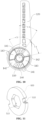
- the first matching structure 140 and the second matching structure 310 may be a ratchet-like structure.
- an end of the first hinge seat 100 facing the sliding member 300 may be provided with the ratchet-like structure, comprising a plurality of first grooves at circumferential intervals.
- the number of the first grooves may be two, three, or more, but in general, the number of the first grooves is set to two based on considering the occupied space and strength.
- a wall surface of a side wall of the first groove forms the first curved surface 141, and an end surface of the side wall of the first groove (i.e., a top surface of the side wall of the first groove) forms the first matching surface 142;
- the sliding member 300 is provided in a roughly cylindrical shape, and an end of the sliding member 300 towards the hinge seat 100 may be provided with the ratchet-like structure, comprising a plurality of second grooves at circumferential intervals.
- the second grooves correspond to the first grooves one by one, and a wall surface of a side wall of the second groove (i.e., a top surface of the side wall of the second groove) forms the second curved surface 311, and an end surface of the side wall of the second groove forms the second matching surface 312.
- the first matching structure 140 and the second matching structure 310 may slide relative to each other, causing different positions of the first matching structure 140 to match with different positions of the second matching structure 310.
- the hinge 10 When the door body 30 is closed, the hinge 10 may be in the first state, and the first matching surface 142 is abuts against the second matching surface 312.
- the elastic member 400 is in a compressed state, and the first matching surface 142 and the second matching surface 312 may be set as end surfaces perpendicular to the first direction X.
- the thrust applied by the elastic member 400 to the sliding member 300 will not cause the hinge 10 to generate a torque, and the door body 30 may be covered on the cabinet 20 by gravity.
- the first matching surface 142 slides relative to the second matching surface 312 and gradually transforms into a state that the first curved surface 141 abuts against the second curved surface 311, the first curved surface 141 slides relative to the second curved surface 311 on the second curved surface 311, and the elastic member 400 gradually resets while applying a gradually-decreased thrust to the sliding member 300.
- the thrust applied by the elastic member 400 to the sliding member 300 generates a force in a radial tangent direction at the contact position between the first curved surface 141 and the second curved surface 311, and this force causes the door body 30 to have a trend to rotate towards the opening direction, thereby balancing the gravity of the door body 30.
- the first curved surface 141 and the second curved surface 311 may still maintain contact, and when the door body 30 is opened to the maximum opening degree, the ratchet-like structure of the first hinge seat 100 and the ratchet-like structure of the sliding member 300 may engage and fit, that is, the side wall of the first groove inserts into the second groove, and the side wall of the second groove inserts into the first groove.
- the first matching surface 142 may abut against the bottom surface (a second bottom surface 313) of the second groove
- the second matching surface 312 may abut against the bottom surface (a first bottom surface 143) of the first groove.
- the elastic member 400 may be a spring, and the spring may always be in a compressed state after the hinge 10 is assembled, to make the spring apply thrust to the sliding member 300.
- the hinge 10 may be connected between the cabinet 20 and the door body 30 of the opening and closing device (such as a freezer), so that the door body 30 is hinged with the cabinet 20.
- the door body 30 may be connected to the first hinge seat 100
- the cabinet 20 may be connected to the second hinge seat 200.
- the first hinge seat 100 may rotate relative to the second hinge seat 200 in the first rotation direction to open the door body 30.
- the hinge 10 may convert a lateral force of the elastic member 400 (i.e., the spring) into a force consistent with the rotation direction of the first hinge seat 100 through the matching of the sliding member 300 and first matching structure 140, ultimately achieving the rotation of the hinge 10 and the opening and closing of the door body 30.
- the elastic member 400 causes the first hinge seat 100 to have a force to rotate in the first rotation direction relative to the second hinge seat 200, that is, the thrust applied by the elastic member 400 to the sliding member 300 may assist the opening of the door body 30 through the first curved surface 141 and the second curved surface 311; during the process of closing the door body 30, the force exerted by the elastic member 400 on the hinge 10 may balance at least a part of the gravity of the door body 30, alleviating the problem of rapid dropping of the door body 30, which avoids a severe collision between the door body 30 and the cabinet 20, and improves the user experience.
- the elastic member 400 and the sliding member 300 are both provided in the first cavity 230 of the second hinge seat 200.
- the hinge 10 may convert the thrust of the elastic member 400 along the first direction X into a rotational force of the hinge 10.
- the hinge 10 has a simple structure and is easy to assemble, having a small space occupation, increasing the number of opening and closing devices that may be loaded on the transport, and reducing the transportation costs.
- both the elastic member 400 and the sliding member 300 are disposed in the first accommodating cavity 230 of the second hinge seat 200.
- the elastic member 400 is a built-in member, which reduces the risk that the hinge 10 pinches the fingers of users or assembly personnel and improves safety.
- the axial force of the elastic member 400 in the first direction X may be converted into a relative large torque for rotation of the first hinge seat 100 through the first matching structure 140 and the second matching structure 310.
- the elasticity required for the elastic member 400 is reduced.
- the wire diameter of the spring may be about 2.5 mm, and the outer diameter of the overall spring may be no more than 16 mm, for example, which may be 15.8 mm, etc. Due to the reduction of the size of the elastic member 400, an impact of the hinge 10 on the space occupancy rate of the opening and closing device may be reduced, that is, a protrusion of the rear side of the hinge 10 from the side wall of the cabinet 20 may be reduced.
- the protrusion of the hinge 10 from the side wall of the cabinet 20 in the present embodiment may be no more than 10 mm, which enhances an overall loading volume of the product and saves transportation costs.
- the first hinge seat 100 is connected to the door body 30 of the opening and closing device
- the second hinge seat 200 is connected to the cabinet 20 of the opening and closing device.
- the first hinge seat 100 may be connected to the cabinet 20 of the opening and closing device
- the second hinge seat 200 may be connected to the door body 30 of the opening and closing device as required. That is, the first hinge seat 100 is fixedly disposed relative to the cabinet 20, and the second hinge seat 200 rotates synchronously together with the door body 30.
- the first hinge seat 100 is fixed. Based on the relativity of motion, the rotation of the first hinge seat 100 relative to the second hinge seat 200 may be achieved through the rotation of the second hinge seat 200.
- first matching surface 142 and the second matching surface 312 may not be flat surfaces perpendicular to the first direction X.
- the settings of the first matching surface 142 and the second matching surface 312 are that as long as they do not cause the thrust applied by the elastic member 400 to the sliding member 300 to generate a force that causes the door body 30 to open.
- the first matching surface 142 and the second matching surface 312 may also be curved surfaces.
- the curved surface serving as the first matching surface 142 is opposite to a spiral direction of the first curved surface 141, and the curved surface serving as the second matching surface 312 is opposite to a spiral direction of the second curved surface 311. Therefore, when the first matching surface 142 abuts against the second matching surface 312, the elastic member 400 may generate a force to rotate the door body 30 towards the closing direction, thereby the door body 30 better covers the cabinet 20.
- the first hinge seat 100 comprises a first lock plate 120 and a first hinge portion 110.
- the first lock plate 120 is integrated with the first hinge portion 110, and the first matching structure 140 is provided on the first hinge portion 110.
- the second hinge seat 200 comprises a second lock plate and a second hinge portion 210, the second lock plate is integrated with the second hinge portion 210.
- the first accommodating cavity 230 is provided with a second hinge portion 210.
- the first hinge portion 110 and the second hinge portion 210 may be rotatably connected, the first lock plate 120 is connected to the door body 30 of the opening and closing device, and the second lock plate is connected to the cabinet 20 of the opening and closing device.
- the first hinge seat 100 may be injection-molded, that is, the first lock plate 120 and the first hinge portion 110 are formed through injection molding.
- the second hinge seat 200 may be injection-molded, that is, the second lock plate and the second hinge portion 210 are formed through injection molding.
- the first lock plate 120 may be provided with one or more first mounting hole 121 used for being matched with a fixing member to fix the first lock plate 120 on the door body 30.
- the fixing member may be a bolt, a screw, etc. In an embodiment, the fixing member is a bolt.
- the second lock plate comprises a first sub-lock plate 221 and a second sub-lock plate 222, where the second sub-lock plate 222 is provided with one or more second mounting holes 223, used for being matched with the fixing member to fix the second sub-lock plate 222 on the cabinet 20.
- the fixing member may be a bolt, a screw, etc.
- the first sub-lock plate 221 is fixedly connected to the second hinge portion 210, and the first sub-lock plate 221 is located on a side of the second sub-lock plate 222 close to the door body 30.
- the first sub-lock plate 221 is inserted into and fixed with the cabinet 20, and the first sub-lock plate 221 may be inserted into and matched with a trench 105 disposed horizontally or vertically on the cabinet 20.
- the first sub-lock plate 221 is connected to the cabinet 20 through insertion. During the opening process of the door body 30, i.e., when the first hinge seat 100 rotates, the first sub-lock plate 221 is the main part that bears the torque, while the second sub-lock plate 222 is fixed through the second mounting hole, which may strengthen the fixation of the second hinge seat 200 with the door body 30 and prevent the second hinge seat 200 from moving. Both the first sub-lock plate 221 and the second sub-lock plate 222 may be integrated with the second hinge portion 210.
- the first lock plate 120 has a door body mounting surface facing the door body 30.
- the door body mounting surface may be a flat surface, and the first lock plate 120 is attached to an end surface of the door body 30 through the door body mounting surface.
- a bolt or screw passes through the first mounting hole 121 and is fixedly connected to the door body 30 to fixedly connect the first lock plate 120 to the door body 30.
- the second sub-lock plate 222 has a cabinet mounting surface facing the cabinet 20, and the cabinet mounting surface may be a flat surface.
- the second sub-lock plate 222 is attached to an outer side of the cabinet 20 through the cabinet 20 mounting surface, and a bolt or screw passes through the second mounting hole 223 and is fixedly connected to the side wall of the cabinet 20 (when the second sub-lock plate 222 is attached to the rear side, the side wall is the rear side wall), and the second sub-lock plate 222 is firmly connected to the cabinet 20.
- the hinge 10 may be provided on a rear side of the opening and closing device
- the first lock plate 120 may be attached and fixedly connected to a rear end surface of the door body 30, and the second sub-lock plate 222 may be attached and fixedly connected to the rear side of the cabinet 20.
- the first lock plate 120 and the second sub-lock plate 222 are roughly provided in a vertical direction, that is, the comprised angle between the first lock plate 120 and the second sub-lock plate 222 is 180 degrees or approximately 180 degrees.
- the first lock plate 120 and the first hinge portion 110 rotate backwards synchronously, and the angle between the first lock plate 120 and the second sub-lock plate 222 on the side facing the opening and closing device is increased; and the comprised angle (the sum of this angle and the angle between the first lock plate 120 and the second sub-lock plate 222 on the side facing the opening and closing device is a round angle) between the first lock plate 120 and the second sub-lock plate 222 on the side away from the opening and closing device is decreased.
- the first lock plate 120 may be provided with three first mounting holes 121, where two first mounting holes 121 are provided at intervals and aligned along the first direction X, and one first mounting hole 121 is provided on the side of the two first mounting holes 121 close to the second sub-lock plate 222, i.e., the three first mounting holes 121 may be provided in a triangular pattern in sequence.
- the second sub-lock plate 222 may be provided with two second mounting holes 223, the two second mounting holes 223 provided at intervals and aligned along the first direction X.
- reinforcing ribs 160 may be disposed on the first lock plate 120 and the second sub-lock plate 222.
- the first lock plate 120 is provided with one or more reinforcing ribs 160 on a surface opposite to the door body mounting surface
- the second sub-lock plate 222 is provided with one or more reinforcing ribs 160 on a surface opposite the mounting surface of the cabinet 20.
- the reinforcing ribs 160 may increase the strength of the first lock plate 120 and/or the second sub-lock plate 222, prolong the service life of the first lock plate 120 and the second sub-lock plate 222.
- the reinforcing ribs 160 may be integrated with corresponding lock plates.
- the first lock plate 120 and the second sub-lock plate 222 may be provided with corresponding stop structures.
- the first lock plate 120 is provided with a first stop 122 on a side close to the second hinge portion 210
- the second sub-lock plate 222 is provided with a second stop 224 on a side close to the first hinge portion 110.
- the first stop 122 is matched the second stop 224 to limit the maximum rotation angle between the first hinge seat 100 and the second hinge portion 210 in the first rotation direction.
- the first stop 122 may be integrated with the first lock plate 120, and the second stop 224 may be integrated with the second sub-lock plate 222.
- the first stop 122 may be disposed on a surface opposite to the door body 30 mounting surface on the first lock plate 120, and the second stop 224 may be disposed on an end surface connected to a cabinet body connection surface on the second sub-lock plate 222.
- the first hinge portion 110 is provided with a second accommodating cavity 130, the second opening of the second accommodating cavity 130 is provided opposite to the first opening and communicates with the first opening, the first matching structure 140 is provided in the second accommodating cavity 130, and an end of the first hinge portion 110 with the second opening is connected in a sealed manner to an end of the second hinge portion 210 with the first opening.
- the second accommodating cavity 130 may be in a shape of cylindrical in with an annular cross-section.
- the first matching structure 140 and the second matching structure 310 are matched to slide and in order to improve the smoothness of sliding and reduce the wear of the first matching structure 140 and the second matching structure 310, and lubricating oil may be added between the first matching structure 140 and the second matching structure 310.
- the first hinge portion 110 is provided with the second accommodating cavity 130, the second accommodating cavity 130 is connected in a sealed manner to and communicates with the first accommodating cavity 230, and the first matching structure 140 and the second matching structure 310 may be in a relatively sealed environment, which ensures a long-term use and storage of the lubricating oil.
- an end surface of the second hinge portion 210 with the first opening is provided with an annular first connecting surface 215 and an annular boss 213 protruding from the first connecting surface 215 and the annular boss 213 is located on an inner side of the first connecting surface 215 along a radial direction.
- An end surface of the first hinge portion 110 with the second opening is provided with an annular second connecting surface 111 and an annular step 112 recessed relative to the second connecting surface 111 And a second step is located on an inner side of the second connecting surface 111 along a radial direction.
- the first connecting surface 215 is opposite to the second connecting surface 111
- the annular boss 213 is corresponding to the concave annular step 112
- the annular boss 213 and the annular step 112 may be provided with an annular groove 113 and an annular protrusion 214 matched with each other.
- the annular boss 213 may be provided with an annular protrusion 214
- the annular step 112 may be provided with the annular groove 113
- the annular protrusion 214 is inserted into and matched with the annular groove 113.
- an oil receiving structure i.e., a sealing groove structure, may be formed on an end surface of the first hinge portion 110 connected to the second hinge portion 210, which reduces the risk of leaking the lubricating oil from the connecting end surface of the first hinge portion 110 and the second hinge portion 210.
- At least one of the first matching surface 142, the second matching surface 312, the first curved surface 141 and the second curved surface 311 may be provided with an oil storage tank 144.
- the oil storage tank 144 may be disposed on any one of the first matching surface 142, the second matching surface 312, the first curved surface 141, and the second curved surface 311, or on two, three or four of the second curved surface 142, the fourth curved surface 312, the first curved surface 141, and the third curved surface 311.
- the oil storage tank 144 is a groove formed on a corresponding surface, and one or more oil storage tanks 144 may be disposed on the same matching surface or the same curved surface.
- a sliding structure of the first matching structure 140 of the first hinge seat 100 is provided with the oil storage tank 144, i.e., the oil storage tank 144 may be disposed on the first curved surface 141.
- the oil storage tank 144 may be used to store a part of lubricating oil.
- the lubricating oil may be stored in the oil storage tank 144 to reduce the wear of the first matching structure 140 and the second matching structure 310.
- the first hinge portion 110 or the second hinge portion 210 is provided with a relief hole 250, the relief hole 250 communicates with the first accommodating cavity 230.
- the relief hole 250 provided on the first hinge portion 110 may communicate with the second accommodating cavity 130.
- the relief hole 250 also communicates with the first accommodating cavity 230 since the second accommodating cavity 130 communicates with the first accommodating cavity 230.
- an end of the second hinge portion 210 away from the first opening may also be provided with the relief hole 250, and the relief hole 250 communicates with the first accommodating cavity 230.
- the lubricating oil inside the hinge 10 i.e., inside the first accommodating cavity 230 and an accommodating groove
- the internal space is compressed, resulting in increase in local pressure.
- oil leakage caused by the imbalance of internal air pressure may be avoided.
- the relief hole 250 should be disposed above an oil level of the lubricating oil that may be stored in the first accommodating cavity 230 to reduce the risk of leaking the lubricating oil from the relief hole 250.
- the first hinge seat 100 may be provided with a first positioning portion 150
- the second hinge seat 200 may be provided with a second positioning portion 240.
- the second positioning portion 240 may be matched with the first positioning portion 150 to position the first hinge seat 100 and the second hinge seat 200 at an initial mounting angle, and the first positioning portion 150 may be disconnected from the first hinge seat 100, and/or the second positioning portion 240 may be disconnected from the second hinge seat 200.
- the initial mounting angle is a positioning angle during the assembly process of the first hinge seat 100 and the second hinge seat 200.
- the hinge 10 is connected to the opening and closing device.
- an angle between a first mounting seat facilitating the mounting of the first hinge seat 100 and the door body 30 and a second mounting seat facilitating the mounting of the second hinge seat 200 and the cabinet 20 may be taken as the initial mounting angle.
- the initial mounting angle may be approximately 180 degrees between the first lock plate 120 of the first hinge seat 100 and the second sub-lock plate 222 of the second hinge seat 200.
- the first positioning portion 150 and the second positioning portion 240 are matched to form a self-locking structure of the hinge 10, and the first hinge seat 100 and the second hinge seat 200 are temporarily fixed.
- the first hinge seat 100 may not rotate relative to the second mounting seat, and may position a mounting position between the first hinge seat 100 and the second hinge seat 200 to reduce the risk of mounting the first hinge seat 100 and the second hinge seat 200 by mistake.
- the first positioning portion 150 may be disconnected from the first hinge seat 100, and which may be understood that the connection between the first positioning portion 150 and the first hinge seat 100 may be released, this disconnection may be destructive that may not be recovered or detachable.
- the second positioning portion 240 may be disconnected from the second hinge seat 200, and this disconnection may be destructive that may not be recovered or detachable.
- one of the first positioning portion 150 and the second positioning portion 240 is a groove structure, and the other thereof is a protrusion.
- the protrusion structure of the first hinge seat 100 is assembled into the groove structure of the second hinge seat 200 to prevent the hinge 10 from rotating.
- a root of the protrusion structure is thinned.
- the groove structure may also be designed with a slope to allow the broken protrusion structure to flow out of the groove structure along the slope, which prevents the protrusion structure from leaving in the hinge 10.
- an outer circumferential wall of the sliding member 300 may be provided with a first guiding structure 320 extending along the first direction X
- the first accommodating cavity 230 of the second hinge seat 200 may be provided with a second guiding structure 231 extending along the first direction X.
- the first guiding structure 320 and the second guiding structure 231 are matched to fix the sliding member 300 and the second hinge seat 200 relative to each other in the circumferential direction of the first accommodating cavity 230, and move the sliding member 300 in the first direction X.
- the first guiding structure 320 and the second guiding structure 231 may be matching of a plurality of raised strips and a plurality of recessed grooves.
- the outer circumferential wall of the sliding member 300 is provided with the recessed grooves
- the inner wall of the first accommodating cavity 230 is provided with the raised strips.
- the raised strips are provided in the recessed groove, and the raised strips and the recessed groove may slide relative to each other in the first direction X.
- the raised strips may be in one-to-one correspondence with the recessed grooves, and for example, the number of the raised strips and recessed grooves may be 2 to 8.
- the number of the raised strips and the recessed grooves are four respectively, the four raised strips are arranged at an equal interval along the circumference of the first accommodating cavity 230, and the four corresponding recessed grooves are arranged at an equal interval along the circumference of the sliding member 300.
- the sliding member 300 may move in the stretching and retracting directions of the elastic member 400 (i.e., spring), i.e., the first direction X, and the rotation of the sliding member 300 may be limited, and the sliding member 300 may only slide along the stretching and retracting directions of the elastic member 400 (i.e., spring).
- the elastic member 400 i.e., spring
- the sliding member 300 may only slide along the stretching and retracting directions of the elastic member 400 (i.e., spring).
- the first hinge seat 100, the second hinge seat 200, and the sliding member 300 in the present embodiment are all made of hard plastic parts, for example, wear-resistant materials such as POM (Polyformaldehyde) or nylon.
- the hinge 10 in the present embodiment may be assembled through a connecting shaft 500.
- the first hinge portion 110, the second hinge portion 210, the sliding member 300, and the elastic member 400 are all provided with through holes 510.
- the through holes 510 may be coaxial with the first accommodating cavity 230 and the second accommodating cavity 130.
- the elastic member 400 is a spring
- the through hole 510 of the elastic member 400 is the internal space within the spiral line of the spring
- the connecting shaft 500 passes through the first hinge portion 110 (comprising the first matching structure 140), the sliding member 300 (comprising the second matching structure 310), the elastic member 400, and the second hinge portion 210 in order to fix the first hinge seat 100, the second hinge seat 200, the elastic member 400, and the second hinge seat 200 as a whole.
- the connecting shaft 500 may be fixed by riveting, or it may be fixed and connected by nuts at one or both ends of the connecting shaft 500.
- an end of the first hinge portion 110 away from the second hinge portion 210 may be provided with a shim 600, and the connecting shaft 500 may be riveted or fixed with a nut after passing through the shim 600.
- a notch 610 may be disposed at the edge of the shim 600, and an end surface of the first hinge portion 110 matched with the shim 600 may be provided with a protruding structure.
- the protruding structure is matched with the notch 610 to prevent the shim 600 from rotating with the first hinge seat 100.
- the shim 600 may also be provided at an end of the second hinge portion 210 away from the first hinge portion 110.
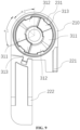
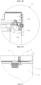
- the central angle corresponding to the second matching surface 312 of the hinge 10 is ⁇ 1.
- the central angle corresponding to the second curved surface 311 is ⁇ 2.
- the central angle corresponding to the projection area formed by the projection of the second matching surface 312 towards the first curved surface 141 is ⁇ 3
- the central angle corresponding to the first matching surface 142 is ⁇ 4
- the central angle corresponding to the second curved surface 311 is ⁇ 5.
- Angles of ⁇ 1, ⁇ 2, ⁇ 3 and ⁇ 4 determine an angle, during the movement of the hinge 10, at which the hinge 10 enters the position of the slope (i.e., the second curved surface 311) of the sliding member 300 from the top of the sliding member 300 (i.e., the second matching surface 312), that is, the angle at which spring force acts on the first hinge seat 100; the minimum hovering angle when opening the door may be determined by adjusting the difference of angle ⁇ 1 and angle ⁇ 3; the difference of angle ⁇ 1 and angle ⁇ 3 is the minimum hover angle when opening the door, which may be 15 degrees to 45 degrees, providing a good user experience; angle ⁇ 2 and angle ⁇ 5 determine the opening angle of the hinge 10.
- the designed opening angle of the door body 30 is generally between 70 degrees and 90 degrees, preferably 80°.
- the angle ⁇ 2 and the angle ⁇ 5 of the hinge 10 is designed greater than 55°, preferably 60°; when designing the angle ⁇ 4, considering the reliability of the closed position of a door and the risk of reverse rotation in the event of a shaking of an upper seat, a design angle of 45° is preferred.
- the centers of ⁇ 1, ⁇ 2, ⁇ 3, ⁇ 4 and ⁇ 5 are all located on the axis of rotation of the first hinge seat relative to the second hinge seat.
- the initial state at the completion of initial assembly of the hinge 10 is shown in FIGS. 1 , 6 , and 7 .
- the door body 30 mounting surface is coplanar with the cabinet 20 mounting surface, and the top sliding surface (the first matching surface 142) of the first hinge seat 100 is in contact with the top mounting surface (the second matching surface 312) of the sliding member 300.
- the spring force is transmitted to the top sliding surface of the first hinge seat 100 through the top sliding surface of sliding member 300, and the force is transmitted along the axial direction, so that the sliding member 300 of the first hinge seat 100 is not subjected to a lateral force, thereby not generating a force to open the door; when the door body 30 is opened and the hinge 10 rotates, the top sliding surface of the first hinge seat 100 remains in contact with the top mounting surface of the sliding member 300; when the hinge 10 rotates to a certain angle (the angle depends on the size of the top surface, combined with user experience and a requirement for force to open the door; the angle may be 20-40°), as shown in FIGS.
- the sliding slope (the first curved surface 141) of the first hinge seat 100 contacts the sliding slope (the second curved surface 311) of the sliding member 300.
- the spring force acts on the sliding member 300, and the sliding member 300, through the angle of the slope of the sliding member 300, decomposes the force into forces along the axis and perpendicular to the tangent of the slope; the force perpendicular to the tangent may be decomposed into a force perpendicular to the axis and under the action of this force, the first hinge seat 100 is subjected to a force that opens the door upwards, which may offset part of the gravity of the door body 30 and assist in opening the door; as the rotation angle of the hinge 10 increases, the force acting on the upper seat decreases and the torque of the door body 30 for rotation decreases, and the force required to open the door body 30 also decreases, thereby achieving a multi-angle hovering of the door body 30; as the rotation angle of the hinge 10 further increases, the first stop 122 of
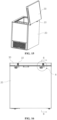
- Some embodiments of the present application further provide an opening and closing device, comprising a cabinet 20 and a door body 30.
- An end of the cabinet 20 has an opening 206, and the door body 30 is hinged to the opening 206 of the cabinet 20 through the hinge 10 proposed in the present application or any embodiment of the present application.
- a first rotation direction is the same as a rotation direction when the door body 30 is opened.
- the opening and closing device may be a freezer, especially the bedroom freezer with an upward opening door.
- the opening and closing device may also be other devices that may be opened and closed, such as a dishwasher, a storage cabinet, etc.
- the first hinge seat 100 is the upper seat connected to the door body 30
- the second hinge seat 200 is the lower seat connected to the cabinet 20 (i.e., the cabinet body)
- the freezer further comprises control parts for controlling the cooling.
- the top (i.e., the first matching surface 142) of the first matching structure 140 of the first hinge seat 100 contacts the top (i.e., the second matching surface 312) of the second matching structure 310 of the sliding member 300 embedded in the second hinge seat 200.
- the elastic member 400 i.e., the spring
- the elastic member 400 is in a compressed state, but the force of the spring cannot be transmitted to the rotation direction, thereby not assisting in opening the door; when the door body 30 of the freezer opens under the force of a hand of a user, the slope (i.e., the first curved surface 141) of the first matching structure 140 of the first hinge seat 100 contacts the slope (i.e., the second curved surface 311) of the second matching structure 310.
- the thrust of the spring acts on the first hinge seat 100 through the slope (i.e., the curved surface), providing a force assisting the door body 30 to open, and the spring has the function of assisting the door body 30 to open; in addition, the support force provided by the spring to the door body 30 is balanced with the gravity and friction of the door body 30, and the support force may play a role in the hovering of the door body 30 in a door opening state.
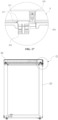
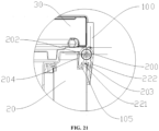
- the outer wall of the cabinet 20 is provided with a mounting cavity 204 recessed towards an interior of the cabinet 20, the mounting cavity 204 is provided with a third opening 202 facing the opening and a fourth opening 203 facing the exterior of the cabinet 20, and a side of the mounting cavity 204 away from the third opening 202 is provided with a trench 105;
- the door body 30 may be connected to the opening 206 of the cabinet 20 through the hinge 10 for opening and closing.
- the hinge 10 comprises a second hinge seat 200 and a first hinge seat 100 rotatably connected.
- the first hinge seat 100 is connected to the side wall of the door body 30, and both hinged ends of the second hinge seat 200 and the first hinge seat 100 are provided in the mounting cavity 204.
- a first sub-lock plate 221 and a second sub-lock plate 222 are provided on a hinged end of the second hinge seat 200 facing away from the first hinge seat 100, the first sub-lock plate 221 is embedded in the trench 105, and the second sub-lock plate 222 is connected to the outer wall of the door body 30.
- the hinge 10 for connecting the door body 30 and the cabinet 20 comprises the second hinge seat 200 and the first hinge seat 100 rotatably connected, where the second hinge seat 200 is connected to the outer surface of the door body 30, and both the hinged ends of the second hinge seat 200 and the first hinge seat 100 are provided in the mounting cavity 204. Since the mounting cavity 204 is recessed from the outer wall of the cabinet 20 to the interior of the cabinet 20, the size of the hinge 10 protruding outside the cabinet 20 may be reduced to a certain extent, the gap between the device and a package box for packaging the device is decreased, the packaging quantity of the product is improved, the transportation costs of the product is reduced, and good practicality is achieved.
- the cabinet 20 may be provided with only one or more openings. When a plurality of openings are disposed, a plurality of door bodies 30 may also be provided. Some of the door bodies 30 may be connected to the opening of the corresponding cabinet 20 using the above assembly method. For door bodies 30 that do not affect the packing quantity, the assembly method in relevant technologies may also be used without any restrictions.
- the opening of the freezer is usually disposed at the top of the product. If the opening is provided at other parts, it may be adjusted accordingly and will not be elaborated here.
- the first hinge seat 100 may comprise a first lock plate 120, the first lock plate 120 may be provided with two second mounting holes 223, and the second mounting hole 223 may be a bolt hole.
- the first lock plate 120 is connected to the door body 30 through a bolt provided in the corresponding second mounting hole 223 to assemble the first hinge seat 100 onto the door body 30.
- the second mounting hole 223 of the embodiments of the present application may be disposed at intervals in the vertical direction, and only two bolts are required to assemble the first lock plate 120 onto the door body 30. In other embodiments, the second mounting hole 223 may also be disposed at intervals in the horizontal direction, or more second mounting holes 223 may be provided, without limitation herein.
- the hinged end of the first hinge seat 100 may be cylindrical and is integrated with the first lock plate 120.
- a side of the first lock plate 120 facing the door body 30 is a flat surface, and the side of the first lock plate 120 facing away from the door body 30 may be provided with a plurality of reinforcing ribs 160.
- the reinforcing rib 160 may be vertically disposed, and the reinforcing rib 160 may extend from the first lock plate 120 to the circumferential surface of the hinged end of the first hinge seat 100 to enhance the strength of the first hinge seat 100, and prolong the service time of the first hinge seat 100.
- the hinged end of the first hinge seat 100 is provided with a second accommodating cavity 130, and the second accommodating cavity 130 may be provided in a cylindrical shape.
- the axial end of the second accommodating cavity 130 facing the second hinge seat 200 is provided with an opening, the opening being the second opening.
- the hinged end of the second hinge seat 200 may also be cylindrical, and the first sub-lock plate 221 and the second sub-lock plate 222 may be provided opposite on both sides of the hinged end of the second hinge seat 200.
- the first sub-lock plate 221 and the second sub-lock plate 222 may be integrated with the hinged end of the second hinge seat 200.
- the vertical size of the second sub-lock plate 222 may be larger than the vertical size of the first sub-lock plate 221 to facilitate the assembly of the first sub-lock plate 221 and the second sub-lock plate 222 on the mounting cavity 204.
- the second sub-lock plate 222 is provided with two first mounting holes 121, and the first mounting holes 121 may be a bolt hole.
- the second sub-lock plate 222 is connected to the outer side of the cabinet 20 through a bolt provided in the corresponding first mounting hole 121.
- the first mounting hole 121 may be rounded rectangular, which facilitates the adjustment of the mounting position of the second hinge seat 200 and the assembly of the hinge 10 on the opening and closing device.
- the first mounting holes 121 may be disposed at intervals in the horizontal direction, and only two bolts are required to assemble and connect the second sub-lock plate 222 to the cabinet 20. In other embodiments, the first mounting hole 121 may also be disposed at intervals in the vertical direction, or more first mounting holes 121 may be provided, without limitation herein.
- first mounting hole 121 and the second mounting hole 223 in the embodiments of the present application are both counter bores to avoid corresponding bolts protruding out of the surface and affecting the packaging quantity of the product.
- the side of the second sub-lock plate 222 facing away from the first sub-lock plate 221 (i.e., the outer side of the second sub-lock plate 222) is provided with a plurality of reinforcing ribs 160.
- the reinforcing ribs 160 may be provided in the vertical direction, and may extend from the second sub-lock plate 222 to the circumferential surface of the hinged end of the second hinge seats to improve the strength of the second hinge seat 200 and prolong the service time of the second hinge seat 200.
- the hinged end of the second hinge seat 200 is provided with a first accommodating cavity 230, and the first accommodating cavity 230 may be provided in a cylindrical shape.
- the second accommodating cavity 130 is open towards the axial end of the first hinge seat 100, i.e., a second opening is provided.
- the second accommodating cavity 130 and the first accommodating cavity 230 are provided opposite to each other, an end of the second accommodating cavity 130 and the first accommodating cavity 230 is open, and an opposite end of the second accommodating cavity 130 and the first accommodating cavity 230 is respectively pressed against two ends of the trench 105.
- embodiment 2 is mainly different from embodiment 1 in that the connection structure between the hinge 10, the cabinet 20, and the door body 30 is different.
- the first lock plate 120 may be provided with three first mounting holes 121, where the two first mounting holes 121 are provided at intervals and aligned in the first direction X, and one first mounting hole 121 is provided on the side of the two first mounting holes 121 close to the second sub-lock plate 222, that is, the three first mounting holes 121 may be provided in a triangular pattern in sequence.
- the door body 30 is provided with a slot 207 at both ends of the trench 105, and raised strip 211 protrudes from the end surface of the second hinge portion 210 away from the first hinge seat 100. Both ends of the trench 105 are provided with slots 207.
- the first hinge seat 100 and the second hinge seat 200 are provided in the mounting cavity 204, and the raised strips 211 is inserted into the slot 207 at the corresponding end.
- the slot 207 are matched with the raised strips 211 to embed and fix the first sub-lock plate 221 and the cabinet 20.
- the second hinge portion 210 is provided with an extension portion 212 integrated with the raised strip 211 on an end surface away from the first hinge seat 100.
- the raised strip 211 is prone to be damaged due to stress concentration.
- the extension portion 212 By providing an extension portion 212, the length of the raised strips 211 is extended, and the strength of the corresponding raised strip 211 is enhanced. In actual testing, the possibility of the raised strip 211 being damaged was found greatly reduced.
- a raised strip 211 may also be provided on an end surface of the first hinge portion 110 facing away from the second hinge portion 210, and the raised strips 211 may also be matched with the corresponding slot 207 at a corresponding end.
Landscapes
- Engineering & Computer Science (AREA)
- Mechanical Engineering (AREA)
- Chemical & Material Sciences (AREA)
- Combustion & Propulsion (AREA)
- Physics & Mathematics (AREA)
- Thermal Sciences (AREA)
- General Engineering & Computer Science (AREA)
- Pivots And Pivotal Connections (AREA)
- Closing And Opening Devices For Wings, And Checks For Wings (AREA)
Abstract
Description
- The present application relates to the field of household appliances, in particular to a hinge and an opening and closing device.
- This section only provides background information related to the present application and does not necessarily refer to prior art.
- A freezer is a common type of opening and closing device, and it is generally provided with an upward opening door structure. When a door body of the freezer is opened, it is necessary to overcome the gravity of the door body, which makes it laborious to open the door body. When the door body of the freezer is closed, the door body may fall fast due to gravity, causing a severe collision between the door body and a cabinet body of the freezer, affecting the user's experience. In some technologies, providing an auxiliary structure on a hinge may provide some assistance during a door opening process and alleviate the problem of rapid dropping of the door body due to gravity and inertia during a door closing process. However, the providing of the auxiliary structure makes the hinge structure complex and occupy a large space, resulting in more labor in hinge assembly. Moreover, due to the increase in space occupied by the hinge, the size of the entire freezer will increase. When transporting the freezer, the increase in space occupied by the freezer reduces the number of freezers that may be loaded by transport and increases transportation costs.
- The purpose of the present application is to at least solve the problem of a complex hinge structure and large space occupation. The purpose of the present application is achieved through the following solution.
- A hinge according to the embodiments of the present application, comprises:
- a first hinge seat, having a first matching structure, where the first matching structure has a first curved surface and a first matching surface;
- a second hinge seat, having a first accommodating cavity extending in a first direction, wherein an end of the first accommodating cavity has a first opening;
- a sliding member, provided in the first accommodating cavity, where the sliding member and the second hinge seat are fixed relatively in a circumferential direction of the first accommodating cavity, the sliding member is slidable along the first direction in the first accommodating cavity, and the sliding member has a second matching structure, the second matching structure has a second curved surface and a second matching surface, the second matching structure abuts against the first matching structure through the first opening; and
- an elastic member, provided in the first accommodating cavity and located at an end of the sliding member facing away from the first matching structure, where the elastic member applies a thrust to the sliding member to move the sliding member towards the first matching structure;
- where the hinge has a first state and a second state, and the first hinge seat is reciprocally rotatable relative to the second hinge seat around an axis extending in the first direction within a predetermined angle range, so as to slide the first matching structure relative to the second matching structure and switch the hinge between the first state and the second state; and in the first state, the first matching surface abuts against the second matching surface, and in the second state, the first curved surface abuts against the second curved surface to cause the first hinge seat and the second hinge seat to have a force for relative rotation under the thrust.
- According to the hinge of the present application, the hinge may be connected between the cabinet and the door body of an opening and closing device (such as a freezer), to hinge the door body with the cabinet. The door body may be connected to the first hinge seat, and the cabinet may be connected to the second hinge seat. During an opening process of the door body, when the hinge rotates to the second state, the thrust generated by the elastic member under the matching of the first curved surface and the second curved surface may cause the first hinge seat and the second hinge seat to have a relative rotational force, i.e., cause the first hinge seat to have a relative rotational torque to the second hinge seat, the thrust applied by the elastic member to the sliding member may assist the opening of the door body through the first curved surface and the second curved surface; during the closing process of the door body, the elastic member forms a force on the hinge that may at least balance a part of gravity of the door body, alleviating the problem of rapid dropping of the door body which causes a severe collision between the door body and the cabinet, and improving the user experience. The elastic member and the sliding member are both provided in the first accommodating cavity of the second hinge seat. The hinge may convert the thrust of the elastic member along the first direction into a force in the rotation direction of the hinge. The hinge has a simple structure and is easy to assemble, reduces the occupied space, increases the number of opening and closing devices that may be loaded on the transport, and reduces the transportation costs of the opening and closing device.
- In addition, the hinge according to the present application may further comprise the following features.
- In some embodiments of the present application, at least either the first curved surface or the second curved surface is a helical surface.
- In some embodiments of the present application, the first curved surface extends along the first direction, and the first matching surface is provided at an end of the first curved surface close to the second matching structure; and the second curved surface extends along the first direction, and the second matching surface is provided at an end of the second curved surface close to the first matching structure.
- In some embodiments of the present application, both the first matching surface and the second matching surface are perpendicular to the first direction.
- In some embodiments of the present application, the first hinge seat comprises a first lock plate and a first hinge portion, the first lock plate is integrated with the first hinge portion, and the first matching structure is provided on the first hinge portion.
- In some embodiments of the present application, the second hinge seat comprises a second lock plate and a second hinge portion, the second lock plate is integrated with the second hinge portion, and the first accommodating cavity is provided with the second hinge portion.
- In some embodiments of the present application, the first lock plate is provided with a first mounting hole, the first mounting hole is matched with a fixing member to fix the first lock plate on an opening and closing device.
- In some embodiments of the present application, the second lock plate comprises a first sub-lock plate and a second sub-lock plate, the first sub-lock plate and the second sub-lock plate are provided at intervals, the first sub-lock plate is embedded in a trench of the opening and closing device, and the second sub-lock plate is provided with a second mounting hole, the second mounting hole is matched with a fixing member to connect the second sub-lock plate with the opening and closing device.
- In some embodiments of the present application, the first hinge portion is provided with a second accommodating cavity, the second accommodating cavity is provided with a second opening, the second opening is opposite to and communicates with the first opening, the first matching structure is provided in the second accommodating cavity, and an end of the first hinge portion provided with the second opening is connected to, in a sealed manner, an end of the second hinge portion provided with the first opening.
- In some embodiments of the present application, at least one of the first matching surface, the second matching surface, the first curved surface and the second curved surface is provided with an oil storage tank.
- In some embodiments of the present application, the second hinge portion is provided with a relief hole at an end away from the first opening, the relief hole communicates with the first accommodating cavity; and/or
the first hinge portion is provided with a relief hole at an end away from the second opening, the relief hole communicates with the second accommodating cavity. - In some embodiments of the present application, a side of the first lock plate close to the second hinge portion is provided with a first stop, a side of the second sub-lock plate close to the first hinge portion is provided with a second stop, and the first stop is matched with the second stop to limit a maximum angle for rotation between the first hinge seat and the second hinge portion.
- In some embodiments of the present application, the first hinge seat is provided with a first positioning portion, and the second hinge seat is provided with a second positioning portion, the second positioning portion is matched with the first positioning portion to position the first hinge seat and the second hinge seat at an initial mounting angle, the first positioning portion is disconnected from the first hinge seat and/or the second positioning portion is disconnected from the second hinge seat.
- In some embodiments of the present application, an outer circumferential wall of the sliding member is provided with a first guiding structure extending in the first direction, and, in the first accommodating cavity, the second hinge seat is provided with a second guiding structure extending in the first direction, the first guiding structure is matched with the second guiding structure, so as to relatively fix the sliding member and the second hinge seat in a circumferential direction of the first accommodating cavity, and to move the sliding member along the first direction.
- In some embodiments of the present application, the first hinge seat, the second hinge seat, and the sliding member are all made of hard plastic parts.
- An opening and closing device according to the present application, comprising:
- a cabinet, having an opening;
- a door body, hinged to the opening of the cabinet through any hinge provided in the present application or any embodiment of the present application.
- The opening and closing device according to the present application, comprising the hinge provided in the present application or any embodiment of the present application, has at least an effect of the effects of the hinge provided in the present application or any embodiment of the present application.
- In addition, the opening and closing device according to the present application may further have the following features.
- In some embodiments of the present application, the opening and closing device is a freezer.
- By reading the detailed description of the preferred embodiments below, other various advantages and benefits will be clear to those ordinarily skilled in the art. The accompanying drawings are only intended to illustrate the preferred embodiments and are not considered a limitation of the present application. Throughout all the drawings, the same part is represented by the same reference sign. In the drawings:
-
FIG. 1 is a schematic diagram of a hinge according to embodiments of the present application; -
FIG. 2 is a split schematic diagram of a hinge according to embodiments of the present application; -
FIG. 3 is a schematic diagram of a sliding member from a perspective according to embodiments of the present application; -
FIG. 4 is a schematic diagram of a first hinge seat from a perspective according to embodiments of the present application; -
FIG. 5 is a schematic diagram of a second hinge seat from a perspective according to embodiments of the present application; -
FIG. 6 is a schematic section diagram of a hinge in a direction according to embodiments of the present application; -
FIG. 7 is a schematic section diagram of a hinge in another direction according to embodiments of the present application; -
FIG. 8 is a schematic enlarged view of the T-part inFIG. 7 ; -
FIG. 9 is a schematic diagram of an assembly of a second hinge seat and a sliding member from a perspective according to embodiments of the present application; -
FIG. 10 is a schematic diagram of a first hinge seat from a perspective according to embodiments of the present application; -
FIG. 11 is a schematic diagram of a shim according to embodiments of the present application; -
FIG. 12 is a schematic section diagram of a hinge in a direction according to embodiments of the present application; -
FIG. 13 schematically illustrates an A-A cross-sectional view inFIG. 12 ; -
FIG. 14 schematically illustrates an enlarged view of part S inFIG. 13 ; -
FIG. 15 is a schematic diagram of an opening and closing device according to embodiments of the present application; -
FIG. 16 is a schematic rear diagram of an opening and closing device according to embodiments of the present application; -
FIG. 17 schematically illustrates an enlarged view of part R inFIG. 16 ; -
FIG. 18 schematically illustrates a B-B cross-sectional view inFIG. 16 ; -
FIG. 19 schematically illustrates an enlarged view of part Q inFIG. 18 ; -
FIG. 20 is a schematic partial diagram of an opening and closing device according to embodiments of the present application; and -
FIG. 21 is a schematic assembly diagram of the second hinge seat on the cabinet inFIG. 20 . - Reference numerals:
- 10: hinge;
- 100: first hinge seat; 110: first hinge portion; 111: second connecting surface; 112: annular step; 113: annular groove; 120: first lock plate; 121: first mounting hole; 122: first stop; 130: second accommodating cavity; 140: first matching structure; 141: first curved surface; 142: first matching surface; 143: first bottom surface; 144: oil storage tank; 150: first positioning portion; 160: reinforced rib;
- 200: second hinge seat; 210: second hinge portion; 211: raised strip; 212: extension portion; 213: annular boss; 214: annular protrusion; 215: first connecting surface; 221: first sub-lock plate; 222: second sub-lock plate; 223: second mounting hole; 224: second stop; 230: first accommodating cavity; 231: second guiding structure; 240: second positioning portion; 250: relief hole;
- 300: sliding member; 310: second matching structure; 311: second curved surface; 312: second matching surface; 313: second bottom surface; 320: first guiding structure;
- 400: elastic member;
- 500: connecting shaft; 510: through hole;
- 600: shim; 610: notch;
- 20: cabinet; 202: third opening; 203: fourth opening; 204: mounting cavity; 105: trench; 206: opening; 207: slot;
- 30: door body;
- X: first direction.
- Exemplary embodiments of the present application are described in more detail below with reference to the accompanying drawings. Although the exemplary implementation of the present application is shown in the accompanying drawings, it should be noted that the present application may be implemented in various forms and should not be limited by the implementation described here. The implementation is provided in order to have a more thorough understanding for the present application and to fully convey the scope of the present application to those skilled in the art.
- It should be noted that the terms used in the description are only for the purpose of describing specific exemplary implementation and are not intended to be restrictive. Unless the context clearly indicates otherwise, singular forms such as "a", "one", and "the" used in the description may also indicate to comprise plural forms. The terms "comprise", "comprise", "contain", and "have" are inclusive and therefore indicate the existence of the stated features, steps, operations, elements, and/or parts, but do not exclude the existence or addition of one or more other features, steps, operations, elements, parts, and/or combinations of them. The steps, processes, and operations described in the description are not interpreted as requiring them to be executed in the specific order described or explained, unless the order of execution is explicitly indicated. It should also be noted that additional or alternative steps may be used.
- Although the terms "first", "second", "third", etc., may be used in the description to describe a plurality of elements, parts, regions, layers, and/or sections, these elements, parts, regions, layers, and/or sections should not be limited by these terms. These terms may only be used to distinguish an element, part, region, layer, or section from another element, part, region, layer, or section. Unless explicitly indicated in the context, terms such as "first", "second", and other numerical terms do not imply order or sequence when used in the description. Therefore, the first element, part, region, layer or section discussed below may be referred to as the second element, part, region, layer or section without departing from the teachings of the exemplary implementation.
- For ease of description, spatial relative relationship terms may be used in the description to describe the relationship between an element or feature shown in the figure and another element or feature. The relative relationship terms are, for example, "internal", "external", "inside", "outside", "below", "lower", "above", "upper", etc. This spatial relative relationship term means to comprise different orientations of devices in use or operation, except for those depicted in the diagram. For example, if the device in the diagram is flipped, the elements described as "below other elements or features" or "under other elements or features" will then be oriented as "above other elements or features" or "on other elements or features". Therefore, the example term "below" may comprise both upper and lower orientations. The device may be additionally oriented (rotated by 90 degrees or in other directions) and the spatial relative relationship descriptors used in the description are explained accordingly.
- For an opening and closing device with an upward opening door, such as a freezer, a side of the door body (generally the rear side) and a side of the cabinet (generally the rear side) are hinged to enable the door body to rotate on the hinged side to open and close. Common hinges used for the opening and closing device comprise plain butt hinges and spring-loaded butt hinges. The plain butt hinge has a structure in which the upper seat and lower seat are connected by a rotating shaft, and this type of hinge is simple, without a spring to assist, and may occupy small space. However, when using this type of hinge, the door body only relies on the thrust applied by the user when opening, making it laborious to open the door. Moreover, when closing the door body, the door body falls fast due to gravity and inertia, causing a severe collision between the door body and a cabinet body, affecting the user experience. The working manner of the spring-loaded butt hinge is to vertically provide a compressed spring along the rear side wall of the cabinet body, so that the compressed spring may fit with a connecting rod to provide assistance along an opening direction of the door body to the hinge upper seat during the opening process of the door body. For example, the spring force acts on the connecting rod of the first hinge seat. When the first hinge seat rotates around the rotating shaft, the connecting rod rotates around the rotating shaft. On the one hand, the spring-loaded butt hinge requires a relatively great spring force, because the torque applied by the spring on the connecting rod is relatively low, in order to ensure the thrust, the spring force needs to be sufficiently great, which requires a greater outer diameter of the spring, usually greater than 15 mm. On the other hand, the thickness of the hinge is generally greater than 20 mm after assembly, which takes up a large amount of space and is not conducive to increasing the loading capacity of transport, leading to an increase in transportation costs. In order to alleviate the problem of spring-loaded butt hinges occupying much space, in some technologies, the hinge is provided in the cabinet. However, for a freezer, this will reduce the thickness of the foam layer corresponding to a position where the hinge is provided, bring a risk of condensation at this position. As the thickness of the cabinet continues to decrease, the risk of condensation increases, which affects the quality of the freezer.
- It may be concluded that an urgent problem to be addressed is that reducing the impact of product space occupancy of the hinge without reducing the thickness of the foam layer and without affecting the basic performance of the product.
- In response to the above problems, as shown in
FIGS. 1 to 21 , embodiments of the present application provide ahinge 10. Thehinge 10 comprises afirst hinge seat 100, asecond hinge seat 200, a slidingmember 300, and anelastic member 400. - The
first hinge seat 100 has afirst matching structure 140, thefirst matching structure 140 having a firstcurved surface 141 and afirst matching surface 142. Thesecond hinge seat 200 has a firstaccommodating cavity 230 extending along a first direction X, and an end of the firstaccommodating cavity 230 has a first opening. The slidingmember 300 is provided inside the firstaccommodating cavity 230, and the slidingmember 300 and thesecond hinge seat 200 are fixed opposite in a circumferential direction of the firstaccommodating cavity 230. The slidingmember 300 is slidable in the first direction X within the firstaccommodating cavity 230, and the slidingmember 300 has asecond matching structure 310, thesecond matching structure 310 having a secondcurved surface 311 and asecond matching surface 312. Thesecond matching structure 310 abuts against thefirst matching structure 140 through the first opening. Theelastic member 400 is provided in the firstaccommodating cavity 230 and is located at an end of the slidingmember 300 away from thesecond matching structure 310. Theelastic member 400 applies a thrust to the slidingmember 300 to move the slidingmember 300 towards thefirst matching structure 140. - The
hinge 10 has a first state and a second state. Thefirst hinge seat 100 is reciprocally rotatable relative to thesecond hinge seat 200 around an axis extending in the first direction X within a predetermined angle range, causing thefirst matching structure 140 to slide relative to thesecond matching structure 310, to make thehinge 10 switch between the first state and the second state. In the first state, thefirst matching surface 142 abuts against thesecond matching surface 312, and in the second state, the firstcurved surface 141 abuts against the secondcurved surface 311, to make thefirst hinge seat 100 and thesecond hinge seat 200 have a force for relative rotation under the thrust. - The thrust causes the
first hinge seat 100 and thesecond hinge seat 200 to have a force for relative rotation. For example, the force applied by theelastic member 400 to the slidingmember 300, with the fit of the firstcurved surface 141 and the secondcurved surface 311, has a component force that causes thefirst hinge seat 100 to relatively rotate relative to thesecond hinge seat 200. As such, thefirst hinge seat 100 and thesecond hinge seat 200 have a relative rotation trend or rotate under this force. In other words, theelastic member 400 provides a torque to thefirst hinge seat 100 and thesecond hinge seat 200. When thehinge 10 is assembled to the opening and closing device, in generally, in the second state, thehinge 10 has a trend to rotate the door body towards a direction of opening the door body, that is, thehinge 10 has a force to rotate in the first rotation direction, and the first rotation direction is the same as the direction of opening the door body. - The first
curved surface 141 may be a helical surface. The secondcurved surface 311 may also be a helical surface, and both the firstcurved surface 141 and the secondcurved surface 311 may extend along the first direction X. Thefirst matching surface 142 may be set at an end of the firstcurved surface 141 close to thesecond matching structure 310, and thesecond matching surface 312 may be set at an end of the secondcurved surface 311 close to thefirst matching structure 140. - The
first hinge seat 100 may be connected to thedoor body 30 of the opening and closing device, and thesecond hinge seat 200 may be connected to thecabinet 20 of the opening and closing device. During the opening or closing process of thedoor body 30, thesecond hinge seat 200 is fixed, and thefirst hinge seat 100 rotates synchronously with thedoor body 30. - When the
hinge 10 is assembled on the opening and closing device, the first direction X may be configured to be parallel to the opening of the opening and closing device. When the opening and closing device is placed on a relatively flat ground, the first direction X may be understood as a horizontal direction. In a case where the opening and closing device has an upward opening door structure, the opening and closing side of thedoor body 30 is facing forward, and thehinge 10 is provided at the rear side of the opening and closing device, the first direction X may be a left or right direction of the opening and closing device. - When assembling the
hinge 10, the first state of thehinge 10 may correspond to a closed state of thedoor body 30 of the opening and closing device and a state with a small opening angle of thedoor body 30. The second state may correspond to a maximum opening state of thedoor body 30 of the opening and closing device and a state with a large opening angle of thedoor body 30. In this way, the first rotation direction is also the opening direction of thedoor body 30. For example, a maximum opening angle of thedoor body 30 corresponding to the first state may be within a range of 15 degrees to 45 degrees from the closed state towards the opening direction. For example, the opening angle of thedoor body 30 corresponding to the first state is between 0 to 15 degrees, or 0 to 20 degrees, or 0 to 21 degrees, or 0 to 25 degrees, or 0 to 30 degrees, or 0 to 35 degrees, or 0 to 40 degrees, or 0 to 45 degrees, etc. The maximum opening angle of thedoor body 30 corresponding to the first state corresponds to a maximum opening angle where thehinge 10 may not buffer the closing of thedoor body 30 or assist in the opening of thedoor body 30. In other words, when thedoor body 30 opens from a closed state to exceed the maximum opening angle of thedoor body 30 corresponding to the first state, the firstcurved surface 141 abuts against the secondcurved surface 311, and thehinge 10 may assist in the opening of thedoor body 30; before thedoor body 30 rotates from the maximum open state to the maximum angle of opening corresponding to the first state, the firstcurved surface 141 abuts against the secondcurved surface 311, and thehinge 10 may buffer the closing of thedoor body 30. - In actual assembly, the
elastic member 400 may be provided based on the gravity of thedoor body 30, and theelastic member 400 should make that the torque generated by thehinge 10 in the second state is greater than the torque generated by the gravity of thedoor body 30, so that thedoor body 30 may hover in the second state of thehinge 10. In a case where thedoor body 30 may hover in the second state of thehinge 10, the opening angle of thedoor body 30 corresponding to the second state is also a hovering angle of thedoor body 30. The lower limit of the hovering angle range is consistent with the maximum opening angle of thedoor body 30 corresponding to the first state, that is, the maximum opening angle of thedoor body 30 corresponding to the first state is a critical point for hovering and non-hovering. When the opening angle of thedoor body 30 is greater than the maximum opening angle of thedoor body 30 corresponding to the first state, thedoor body 30 may hover. When the opening angle of thedoor body 30 is smaller than the maximum opening angle of thedoor body 30 corresponding to the first state, thedoor body 30 may not hover. The upper limit of the hovering angle range may be consistent with the angle at which thedoor body 30 opens to the maximum state. - The preset angle range of the rotation of the
first hinge seat 100 relative to thesecond hinge seat 200 corresponds to an opening degree of thedoor body 30, that is, when thedoor body 30 is from the closed state to the maximum opening state, the angle range of the rotation of thedoor body 30 may be used as the preset angle range of the rotation of thefirst hinge seat 100 and thesecond hinge seat 200. In the present embodiment, the angle at which thedoor body 30 opens to the maximum state may be 70 degrees to 90 degrees. For example, the angle range of the rotation of thedoor body 30 may be 0 to 90 degrees, 0 to 85 degrees, 0 to 80 degrees, 0 to 75 degrees, or 0 to 70 degrees. In some technologies, the angle range of rotation of thedoor body 30 may be set to 0 to 80 degrees. At 0 degree, thedoor body 30 is closed, and at 80 degrees, thedoor body 30 is opened to the maximum state. - The first
accommodating cavity 230 may be cylindrical in shape with an annular cross-section. - The
first matching structure 140 and thesecond matching structure 310 may be a ratchet-like structure. In an embodiment, an end of thefirst hinge seat 100 facing the slidingmember 300 may be provided with the ratchet-like structure, comprising a plurality of first grooves at circumferential intervals. For example, the number of the first grooves may be two, three, or more, but in general, the number of the first grooves is set to two based on considering the occupied space and strength. A wall surface of a side wall of the first groove forms the firstcurved surface 141, and an end surface of the side wall of the first groove (i.e., a top surface of the side wall of the first groove) forms thefirst matching surface 142; the slidingmember 300 is provided in a roughly cylindrical shape, and an end of the slidingmember 300 towards thehinge seat 100 may be provided with the ratchet-like structure, comprising a plurality of second grooves at circumferential intervals. The second grooves correspond to the first grooves one by one, and a wall surface of a side wall of the second groove (i.e., a top surface of the side wall of the second groove) forms the secondcurved surface 311, and an end surface of the side wall of the second groove forms thesecond matching surface 312. - When the
first hinge seat 100 rotates relative to thesecond hinge seat 200, thefirst matching structure 140 and thesecond matching structure 310 may slide relative to each other, causing different positions of thefirst matching structure 140 to match with different positions of thesecond matching structure 310. When thedoor body 30 is closed, thehinge 10 may be in the first state, and thefirst matching surface 142 is abuts against thesecond matching surface 312. At this time, theelastic member 400 is in a compressed state, and thefirst matching surface 142 and thesecond matching surface 312 may be set as end surfaces perpendicular to the first direction X. As such, the thrust applied by theelastic member 400 to the slidingmember 300 will not cause thehinge 10 to generate a torque, and thedoor body 30 may be covered on thecabinet 20 by gravity. During the opening process of thedoor body 30, thefirst matching surface 142 slides relative to thesecond matching surface 312 and gradually transforms into a state that the firstcurved surface 141 abuts against the secondcurved surface 311, the firstcurved surface 141 slides relative to the secondcurved surface 311 on the secondcurved surface 311, and theelastic member 400 gradually resets while applying a gradually-decreased thrust to the slidingmember 300. In a case where the firstcurved surface 141 abuts against the secondcurved surface 311, i.e., in the second state, the thrust applied by theelastic member 400 to the slidingmember 300 generates a force in a radial tangent direction at the contact position between the firstcurved surface 141 and the secondcurved surface 311, and this force causes thedoor body 30 to have a trend to rotate towards the opening direction, thereby balancing the gravity of thedoor body 30. When thedoor body 30 is opened to the maximum opening degree, the firstcurved surface 141 and the secondcurved surface 311 may still maintain contact, and when thedoor body 30 is opened to the maximum opening degree, the ratchet-like structure of thefirst hinge seat 100 and the ratchet-like structure of the slidingmember 300 may engage and fit, that is, the side wall of the first groove inserts into the second groove, and the side wall of the second groove inserts into the first groove. Thefirst matching surface 142 may abut against the bottom surface (a second bottom surface 313) of the second groove, and thesecond matching surface 312 may abut against the bottom surface (a first bottom surface 143) of the first groove. - The
elastic member 400 may be a spring, and the spring may always be in a compressed state after thehinge 10 is assembled, to make the spring apply thrust to the slidingmember 300. - According to the present embodiment, the
hinge 10 may be connected between thecabinet 20 and thedoor body 30 of the opening and closing device (such as a freezer), so that thedoor body 30 is hinged with thecabinet 20. Thedoor body 30 may be connected to thefirst hinge seat 100, and thecabinet 20 may be connected to thesecond hinge seat 200. Thefirst hinge seat 100 may rotate relative to thesecond hinge seat 200 in the first rotation direction to open thedoor body 30. In the present embodiment, thehinge 10 may convert a lateral force of the elastic member 400 (i.e., the spring) into a force consistent with the rotation direction of thefirst hinge seat 100 through the matching of the slidingmember 300 andfirst matching structure 140, ultimately achieving the rotation of thehinge 10 and the opening and closing of thedoor body 30. In an embodiment, during the opening process of thedoor body 30, when thehinge 10 rotates to the second state, theelastic member 400 causes thefirst hinge seat 100 to have a force to rotate in the first rotation direction relative to thesecond hinge seat 200, that is, the thrust applied by theelastic member 400 to the slidingmember 300 may assist the opening of thedoor body 30 through the firstcurved surface 141 and the secondcurved surface 311; during the process of closing thedoor body 30, the force exerted by theelastic member 400 on thehinge 10 may balance at least a part of the gravity of thedoor body 30, alleviating the problem of rapid dropping of thedoor body 30, which avoids a severe collision between thedoor body 30 and thecabinet 20, and improves the user experience. Theelastic member 400 and the slidingmember 300 are both provided in thefirst cavity 230 of thesecond hinge seat 200. Thehinge 10 may convert the thrust of theelastic member 400 along the first direction X into a rotational force of thehinge 10. Thehinge 10 has a simple structure and is easy to assemble, having a small space occupation, increasing the number of opening and closing devices that may be loaded on the transport, and reducing the transportation costs. - Furthermore, both the
elastic member 400 and the slidingmember 300 are disposed in the firstaccommodating cavity 230 of thesecond hinge seat 200. Theelastic member 400 is a built-in member, which reduces the risk that thehinge 10 pinches the fingers of users or assembly personnel and improves safety. - In the present embodiment, the axial force of the
elastic member 400 in the first direction X may be converted into a relative large torque for rotation of thefirst hinge seat 100 through thefirst matching structure 140 and thesecond matching structure 310. In this way, the elasticity required for theelastic member 400 is reduced. In a case where theelastic member 400 is a spring, the wire diameter of the spring may be about 2.5 mm, and the outer diameter of the overall spring may be no more than 16 mm, for example, which may be 15.8 mm, etc. Due to the reduction of the size of theelastic member 400, an impact of thehinge 10 on the space occupancy rate of the opening and closing device may be reduced, that is, a protrusion of the rear side of thehinge 10 from the side wall of thecabinet 20 may be reduced. Combined with the reasonable design of thecabinet 20, when mounting thehinge 10 to the opening and closing device, the protrusion of thehinge 10 from the side wall of thecabinet 20 in the present embodiment may be no more than 10 mm, which enhances an overall loading volume of the product and saves transportation costs. - It should be noted that in the present embodiment, the
first hinge seat 100 is connected to thedoor body 30 of the opening and closing device, and thesecond hinge seat 200 is connected to thecabinet 20 of the opening and closing device. However, during actual assembly, thefirst hinge seat 100 may be connected to thecabinet 20 of the opening and closing device, and thesecond hinge seat 200 may be connected to thedoor body 30 of the opening and closing device as required. That is, thefirst hinge seat 100 is fixedly disposed relative to thecabinet 20, and thesecond hinge seat 200 rotates synchronously together with thedoor body 30. Thefirst hinge seat 100 is fixed. Based on the relativity of motion, the rotation of thefirst hinge seat 100 relative to thesecond hinge seat 200 may be achieved through the rotation of thesecond hinge seat 200. - It should also be noted that the
first matching surface 142 and thesecond matching surface 312 may not be flat surfaces perpendicular to the first direction X. The settings of thefirst matching surface 142 and thesecond matching surface 312 are that as long as they do not cause the thrust applied by theelastic member 400 to the slidingmember 300 to generate a force that causes thedoor body 30 to open. For example, thefirst matching surface 142 and thesecond matching surface 312 may also be curved surfaces. The curved surface serving as thefirst matching surface 142 is opposite to a spiral direction of the firstcurved surface 141, and the curved surface serving as thesecond matching surface 312 is opposite to a spiral direction of the secondcurved surface 311. Therefore, when thefirst matching surface 142 abuts against thesecond matching surface 312, theelastic member 400 may generate a force to rotate thedoor body 30 towards the closing direction, thereby thedoor body 30 better covers thecabinet 20. - According to some embodiments of the present application, as shown in
FIGS. 1 ,2 , and4 , thefirst hinge seat 100 comprises afirst lock plate 120 and afirst hinge portion 110. Thefirst lock plate 120 is integrated with thefirst hinge portion 110, and thefirst matching structure 140 is provided on thefirst hinge portion 110. Thesecond hinge seat 200 comprises a second lock plate and asecond hinge portion 210, the second lock plate is integrated with thesecond hinge portion 210. The firstaccommodating cavity 230 is provided with asecond hinge portion 210. Thefirst hinge portion 110 and thesecond hinge portion 210 may be rotatably connected, thefirst lock plate 120 is connected to thedoor body 30 of the opening and closing device, and the second lock plate is connected to thecabinet 20 of the opening and closing device. - The
first hinge seat 100 may be injection-molded, that is, thefirst lock plate 120 and thefirst hinge portion 110 are formed through injection molding. Thesecond hinge seat 200 may be injection-molded, that is, the second lock plate and thesecond hinge portion 210 are formed through injection molding. - The
first lock plate 120 may be provided with one or more first mountinghole 121 used for being matched with a fixing member to fix thefirst lock plate 120 on thedoor body 30. The fixing member may be a bolt, a screw, etc. In an embodiment, the fixing member is a bolt. - The second lock plate comprises a first
sub-lock plate 221 and a secondsub-lock plate 222, where the secondsub-lock plate 222 is provided with one or more second mountingholes 223, used for being matched with the fixing member to fix the secondsub-lock plate 222 on thecabinet 20. The fixing member may be a bolt, a screw, etc. The firstsub-lock plate 221 is fixedly connected to thesecond hinge portion 210, and the firstsub-lock plate 221 is located on a side of the secondsub-lock plate 222 close to thedoor body 30. The firstsub-lock plate 221 is inserted into and fixed with thecabinet 20, and the firstsub-lock plate 221 may be inserted into and matched with atrench 105 disposed horizontally or vertically on thecabinet 20. The firstsub-lock plate 221 is connected to thecabinet 20 through insertion. During the opening process of thedoor body 30, i.e., when thefirst hinge seat 100 rotates, the firstsub-lock plate 221 is the main part that bears the torque, while the secondsub-lock plate 222 is fixed through the second mounting hole, which may strengthen the fixation of thesecond hinge seat 200 with thedoor body 30 and prevent thesecond hinge seat 200 from moving. Both the firstsub-lock plate 221 and the secondsub-lock plate 222 may be integrated with thesecond hinge portion 210. - In an embodiment, as shown in
FIG. 1 ,FIG. 2 , andFIG. 4 in combination withFIG. 16 andFIG. 17 FIGS, thefirst lock plate 120 has a door body mounting surface facing thedoor body 30. The door body mounting surface may be a flat surface, and thefirst lock plate 120 is attached to an end surface of thedoor body 30 through the door body mounting surface. A bolt or screw passes through the first mountinghole 121 and is fixedly connected to thedoor body 30 to fixedly connect thefirst lock plate 120 to thedoor body 30. The secondsub-lock plate 222 has a cabinet mounting surface facing thecabinet 20, and the cabinet mounting surface may be a flat surface. The secondsub-lock plate 222 is attached to an outer side of thecabinet 20 through thecabinet 20 mounting surface, and a bolt or screw passes through thesecond mounting hole 223 and is fixedly connected to the side wall of the cabinet 20 (when the secondsub-lock plate 222 is attached to the rear side, the side wall is the rear side wall), and the secondsub-lock plate 222 is firmly connected to thecabinet 20. In an embodiment, thehinge 10 may be provided on a rear side of the opening and closing device, thefirst lock plate 120 may be attached and fixedly connected to a rear end surface of thedoor body 30, and the secondsub-lock plate 222 may be attached and fixedly connected to the rear side of thecabinet 20. In the closed state of thedoor body 30, thefirst lock plate 120 and the secondsub-lock plate 222 are roughly provided in a vertical direction, that is, the comprised angle between thefirst lock plate 120 and the secondsub-lock plate 222 is 180 degrees or approximately 180 degrees. During the opening process of thedoor body 30, thefirst lock plate 120 and thefirst hinge portion 110 rotate backwards synchronously, and the angle between thefirst lock plate 120 and the secondsub-lock plate 222 on the side facing the opening and closing device is increased; and the comprised angle (the sum of this angle and the angle between thefirst lock plate 120 and the secondsub-lock plate 222 on the side facing the opening and closing device is a round angle) between thefirst lock plate 120 and the secondsub-lock plate 222 on the side away from the opening and closing device is decreased. - In some embodiments, as shown in
FIGS. 1 and2 , thefirst lock plate 120 may be provided with three first mountingholes 121, where two first mountingholes 121 are provided at intervals and aligned along the first direction X, and onefirst mounting hole 121 is provided on the side of the two first mountingholes 121 close to the secondsub-lock plate 222, i.e., the three first mountingholes 121 may be provided in a triangular pattern in sequence. The secondsub-lock plate 222 may be provided with two second mountingholes 223, the two second mountingholes 223 provided at intervals and aligned along the first direction X. - In an embodiment, reinforcing
ribs 160 may be disposed on thefirst lock plate 120 and the secondsub-lock plate 222. For example, thefirst lock plate 120 is provided with one or more reinforcingribs 160 on a surface opposite to the door body mounting surface, and the secondsub-lock plate 222 is provided with one or more reinforcingribs 160 on a surface opposite the mounting surface of thecabinet 20. The reinforcingribs 160 may increase the strength of thefirst lock plate 120 and/or the secondsub-lock plate 222, prolong the service life of thefirst lock plate 120 and the secondsub-lock plate 222. The reinforcingribs 160 may be integrated with corresponding lock plates. - In an embodiment, in order to limit the maximum opening state of the
door body 30, i.e., to limit the opening degree of thedoor body 30, thefirst lock plate 120 and the secondsub-lock plate 222 may be provided with corresponding stop structures. For example, thefirst lock plate 120 is provided with a first stop 122 on a side close to thesecond hinge portion 210, and the secondsub-lock plate 222 is provided with asecond stop 224 on a side close to thefirst hinge portion 110. The first stop 122 is matched thesecond stop 224 to limit the maximum rotation angle between thefirst hinge seat 100 and thesecond hinge portion 210 in the first rotation direction. - The first stop 122 may be integrated with the
first lock plate 120, and thesecond stop 224 may be integrated with the secondsub-lock plate 222. The first stop 122 may be disposed on a surface opposite to thedoor body 30 mounting surface on thefirst lock plate 120, and thesecond stop 224 may be disposed on an end surface connected to a cabinet body connection surface on the secondsub-lock plate 222. - According to some embodiments of the present application, the
first hinge portion 110 is provided with a secondaccommodating cavity 130, the second opening of the secondaccommodating cavity 130 is provided opposite to the first opening and communicates with the first opening, thefirst matching structure 140 is provided in the secondaccommodating cavity 130, and an end of thefirst hinge portion 110 with the second opening is connected in a sealed manner to an end of thesecond hinge portion 210 with the first opening. - The second
accommodating cavity 130 may be in a shape of cylindrical in with an annular cross-section. - The
first matching structure 140 and thesecond matching structure 310 are matched to slide and in order to improve the smoothness of sliding and reduce the wear of thefirst matching structure 140 and thesecond matching structure 310, and lubricating oil may be added between thefirst matching structure 140 and thesecond matching structure 310. Thefirst hinge portion 110 is provided with the secondaccommodating cavity 130, the secondaccommodating cavity 130 is connected in a sealed manner to and communicates with the firstaccommodating cavity 230, and thefirst matching structure 140 and thesecond matching structure 310 may be in a relatively sealed environment, which ensures a long-term use and storage of the lubricating oil. - As shown in
FIGS. 7 and8 , in an embodiment, an end surface of thesecond hinge portion 210 with the first opening is provided with an annular first connectingsurface 215 and anannular boss 213 protruding from the first connectingsurface 215 and theannular boss 213 is located on an inner side of the first connectingsurface 215 along a radial direction. An end surface of thefirst hinge portion 110 with the second opening is provided with an annular second connectingsurface 111 and anannular step 112 recessed relative to the second connectingsurface 111 And a second step is located on an inner side of the second connectingsurface 111 along a radial direction. After thefirst hinge portion 110 is connected to thesecond hinge portion 210, the first connectingsurface 215 is opposite to the second connectingsurface 111, theannular boss 213 is corresponding to the concaveannular step 112, and theannular boss 213 and theannular step 112 may be provided with anannular groove 113 and anannular protrusion 214 matched with each other. For example, theannular boss 213 may be provided with anannular protrusion 214, theannular step 112 may be provided with theannular groove 113, and theannular protrusion 214 is inserted into and matched with theannular groove 113. - By the matching structure between the
annular protrusion 214 on theannular boss 213 and theannular groove 113 on theannular step 112, an oil receiving structure, i.e., a sealing groove structure, may be formed on an end surface of thefirst hinge portion 110 connected to thesecond hinge portion 210, which reduces the risk of leaking the lubricating oil from the connecting end surface of thefirst hinge portion 110 and thesecond hinge portion 210. - According to some embodiments of the present application, as shown in
FIGS. 4 and10 , at least one of thefirst matching surface 142, thesecond matching surface 312, the firstcurved surface 141 and the secondcurved surface 311 may be provided with anoil storage tank 144. - For example, the
oil storage tank 144 may be disposed on any one of thefirst matching surface 142, thesecond matching surface 312, the firstcurved surface 141, and the secondcurved surface 311, or on two, three or four of the secondcurved surface 142, the fourthcurved surface 312, the firstcurved surface 141, and the thirdcurved surface 311. - The
oil storage tank 144 is a groove formed on a corresponding surface, and one or moreoil storage tanks 144 may be disposed on the same matching surface or the same curved surface. - As shown in
FIGS. 4 and10 , in an embodiment of the present application, a sliding structure of thefirst matching structure 140 of thefirst hinge seat 100 is provided with theoil storage tank 144, i.e., theoil storage tank 144 may be disposed on the firstcurved surface 141. - The
oil storage tank 144 may be used to store a part of lubricating oil. When thefirst hinge seat 100 rotates relative to thesecond hinge seat 200, the lubricating oil may be stored in theoil storage tank 144 to reduce the wear of thefirst matching structure 140 and thesecond matching structure 310. - According to some embodiments of the present application, at least either the
first hinge portion 110 or thesecond hinge portion 210 is provided with arelief hole 250, therelief hole 250 communicates with the firstaccommodating cavity 230. When thefirst hinge portion 110 is provided with therelief hole 250, therelief hole 250 provided on thefirst hinge portion 110 may communicate with the secondaccommodating cavity 130. Therelief hole 250 also communicates with the firstaccommodating cavity 230 since the secondaccommodating cavity 130 communicates with the firstaccommodating cavity 230. - In an embodiment, as shown in
FIGS. 1 and5 , an end of thesecond hinge portion 210 away from the first opening may also be provided with therelief hole 250, and therelief hole 250 communicates with the firstaccommodating cavity 230. - When the
hinge 10 rotates, the lubricating oil inside thehinge 10, i.e., inside the firstaccommodating cavity 230 and an accommodating groove, is squeezed, and the internal space is compressed, resulting in increase in local pressure. By setting therelief hole 250, oil leakage caused by the imbalance of internal air pressure may be avoided. - It should be noted that the
relief hole 250 should be disposed above an oil level of the lubricating oil that may be stored in the firstaccommodating cavity 230 to reduce the risk of leaking the lubricating oil from therelief hole 250. - According to some embodiments of the present application, the
first hinge seat 100 may be provided with afirst positioning portion 150, thesecond hinge seat 200 may be provided with asecond positioning portion 240. Thesecond positioning portion 240 may be matched with thefirst positioning portion 150 to position thefirst hinge seat 100 and thesecond hinge seat 200 at an initial mounting angle, and thefirst positioning portion 150 may be disconnected from thefirst hinge seat 100, and/or thesecond positioning portion 240 may be disconnected from thesecond hinge seat 200. - The initial mounting angle is a positioning angle during the assembly process of the
first hinge seat 100 and thesecond hinge seat 200. Generally, after thefirst hinge seat 100 and thesecond hinge seat 200 are assemble, thehinge 10 is connected to the opening and closing device. In order to facilitate the connection of thehinge 10 with thedoor body 30 and thecabinet 20 of the opening and closing device, an angle between a first mounting seat facilitating the mounting of thefirst hinge seat 100 and thedoor body 30 and a second mounting seat facilitating the mounting of thesecond hinge seat 200 and thecabinet 20 may be taken as the initial mounting angle. In the present embodiment, when thedoor body 30 is in a closed state, it is most convenient to assemble the hinge seat and the opening and closing device, and no torque is applied between thefirst hinge seat 100 and thesecond hinge seat 200. Therefore, the initial mounting angle may be approximately 180 degrees between thefirst lock plate 120 of thefirst hinge seat 100 and the secondsub-lock plate 222 of thesecond hinge seat 200. - The
first positioning portion 150 and thesecond positioning portion 240 are matched to form a self-locking structure of thehinge 10, and thefirst hinge seat 100 and thesecond hinge seat 200 are temporarily fixed. Thefirst hinge seat 100 may not rotate relative to the second mounting seat, and may position a mounting position between thefirst hinge seat 100 and thesecond hinge seat 200 to reduce the risk of mounting thefirst hinge seat 100 and thesecond hinge seat 200 by mistake. - The
first positioning portion 150 may be disconnected from thefirst hinge seat 100, and which may be understood that the connection between thefirst positioning portion 150 and thefirst hinge seat 100 may be released, this disconnection may be destructive that may not be recovered or detachable. Similarly, thesecond positioning portion 240 may be disconnected from thesecond hinge seat 200, and this disconnection may be destructive that may not be recovered or detachable. - In an embodiment, one of the
first positioning portion 150 and thesecond positioning portion 240 is a groove structure, and the other thereof is a protrusion. Taking thefirst positioning portion 150 as the protrusion and thesecond positioning portion 240 as the groove, when thehinge 10 is assembled, the protrusion structure of thefirst hinge seat 100 is assembled into the groove structure of thesecond hinge seat 200 to prevent thehinge 10 from rotating. A root of the protrusion structure is thinned. After thehinge 10 is mounted the first time, as an opening of thedoor body 30, due to the protrusion structure being stuck in the groove, the protrusion structure is broken from the root to disconnect thefirst hinge seat 100 from thesecond hinge seat 200 in the circumferential direction, and rotate thehinge 10. - Furthermore, the groove structure may also be designed with a slope to allow the broken protrusion structure to flow out of the groove structure along the slope, which prevents the protrusion structure from leaving in the
hinge 10. - According to some embodiments, an outer circumferential wall of the sliding
member 300 may be provided with afirst guiding structure 320 extending along the first direction X, and the firstaccommodating cavity 230 of thesecond hinge seat 200 may be provided with asecond guiding structure 231 extending along the first direction X. Thefirst guiding structure 320 and thesecond guiding structure 231 are matched to fix the slidingmember 300 and thesecond hinge seat 200 relative to each other in the circumferential direction of the firstaccommodating cavity 230, and move the slidingmember 300 in the first direction X. - For example, the
first guiding structure 320 and thesecond guiding structure 231 may be matching of a plurality of raised strips and a plurality of recessed grooves. For example, in the present embodiment, the outer circumferential wall of the slidingmember 300 is provided with the recessed grooves, and the inner wall of the firstaccommodating cavity 230 is provided with the raised strips. The raised strips are provided in the recessed groove, and the raised strips and the recessed groove may slide relative to each other in the first direction X. The raised strips may be in one-to-one correspondence with the recessed grooves, and for example, the number of the raised strips and recessed grooves may be 2 to 8. In the present embodiment, the number of the raised strips and the recessed grooves are four respectively, the four raised strips are arranged at an equal interval along the circumference of the firstaccommodating cavity 230, and the four corresponding recessed grooves are arranged at an equal interval along the circumference of the slidingmember 300. - By the
first guiding structure 320 and thesecond guiding structure 231, the slidingmember 300 may move in the stretching and retracting directions of the elastic member 400 (i.e., spring), i.e., the first direction X, and the rotation of the slidingmember 300 may be limited, and the slidingmember 300 may only slide along the stretching and retracting directions of the elastic member 400 (i.e., spring). - The
first hinge seat 100, thesecond hinge seat 200, and the slidingmember 300 in the present embodiment are all made of hard plastic parts, for example, wear-resistant materials such as POM (Polyformaldehyde) or nylon. - The
hinge 10 in the present embodiment may be assembled through a connectingshaft 500. Thefirst hinge portion 110, thesecond hinge portion 210, the slidingmember 300, and theelastic member 400 are all provided with throughholes 510. The throughholes 510 may be coaxial with the firstaccommodating cavity 230 and the secondaccommodating cavity 130. When theelastic member 400 is a spring, the throughhole 510 of theelastic member 400 is the internal space within the spiral line of the spring, and the connectingshaft 500 passes through the first hinge portion 110 (comprising the first matching structure 140), the sliding member 300 (comprising the second matching structure 310), theelastic member 400, and thesecond hinge portion 210 in order to fix thefirst hinge seat 100, thesecond hinge seat 200, theelastic member 400, and thesecond hinge seat 200 as a whole. The connectingshaft 500 may be fixed by riveting, or it may be fixed and connected by nuts at one or both ends of the connectingshaft 500. - Furthermore, an end of the
first hinge portion 110 away from thesecond hinge portion 210 may be provided with ashim 600, and the connectingshaft 500 may be riveted or fixed with a nut after passing through theshim 600. - A
notch 610 may be disposed at the edge of theshim 600, and an end surface of thefirst hinge portion 110 matched with theshim 600 may be provided with a protruding structure. The protruding structure is matched with thenotch 610 to prevent theshim 600 from rotating with thefirst hinge seat 100. - It should be noted that the
shim 600 may also be provided at an end of thesecond hinge portion 210 away from thefirst hinge portion 110. - As shown in
FIGS. 9 and10 , in the present embodiment, the central angle corresponding to thesecond matching surface 312 of thehinge 10 is α1. The central angle corresponding to the secondcurved surface 311 is α2. In an initial state that thedoor body 30 is closed (in the initial state, a part of thefirst matching surface 142 abuts against thesecond matching surface 312, and thefirst matching surface 142 also has another part suspended opposite the second curved surface 311), the central angle corresponding to the projection area formed by the projection of thesecond matching surface 312 towards the firstcurved surface 141 is α3, the central angle corresponding to thefirst matching surface 142 is α4, and the central angle corresponding to the secondcurved surface 311 is α5. Angles of α1, α2, α3 and α4 determine an angle, during the movement of thehinge 10, at which thehinge 10 enters the position of the slope (i.e., the second curved surface 311) of the slidingmember 300 from the top of the sliding member 300 (i.e., the second matching surface 312), that is, the angle at which spring force acts on thefirst hinge seat 100; the minimum hovering angle when opening the door may be determined by adjusting the difference of angle α1 and angle α3; the difference of angle α1 and angle α3 is the minimum hover angle when opening the door, which may be 15 degrees to 45 degrees, providing a good user experience; angle α2 and angle α5 determine the opening angle of thehinge 10. The designed opening angle of thedoor body 30 is generally between 70 degrees and 90 degrees, preferably 80°. To ensure that the spring still has an enough force onhinge 10 after opening the door and keep thedoor body 30 supported, the angle α2 and the angle α5 of thehinge 10 is designed greater than 55°, preferably 60°; when designing the angle α4, considering the reliability of the closed position of a door and the risk of reverse rotation in the event of a shaking of an upper seat, a design angle of 45° is preferred. - It should be noted that, the centers of α1, α2, α3, α4 and α5 are all located on the axis of rotation of the first hinge seat relative to the second hinge seat.
- In the present embodiment, the initial state at the completion of initial assembly of the
hinge 10 is shown inFIGS. 1 ,6 , and7 . Whenhinge 10 may be assembled to the opening and closing device in the initial state, thedoor body 30 mounting surface is coplanar with thecabinet 20 mounting surface, and the top sliding surface (the first matching surface 142) of thefirst hinge seat 100 is in contact with the top mounting surface (the second matching surface 312) of the slidingmember 300. The spring force is transmitted to the top sliding surface of thefirst hinge seat 100 through the top sliding surface of slidingmember 300, and the force is transmitted along the axial direction, so that the slidingmember 300 of thefirst hinge seat 100 is not subjected to a lateral force, thereby not generating a force to open the door; when thedoor body 30 is opened and thehinge 10 rotates, the top sliding surface of thefirst hinge seat 100 remains in contact with the top mounting surface of the slidingmember 300; when thehinge 10 rotates to a certain angle (the angle depends on the size of the top surface, combined with user experience and a requirement for force to open the door; the angle may be 20-40°), as shown inFIGS. 12 ,13, and 14 , the sliding slope (the first curved surface 141) of thefirst hinge seat 100 contacts the sliding slope (the second curved surface 311) of the slidingmember 300. The spring force acts on the slidingmember 300, and the slidingmember 300, through the angle of the slope of the slidingmember 300, decomposes the force into forces along the axis and perpendicular to the tangent of the slope; the force perpendicular to the tangent may be decomposed into a force perpendicular to the axis and under the action of this force, thefirst hinge seat 100 is subjected to a force that opens the door upwards, which may offset part of the gravity of thedoor body 30 and assist in opening the door; as the rotation angle of thehinge 10 increases, the force acting on the upper seat decreases and the torque of thedoor body 30 for rotation decreases, and the force required to open thedoor body 30 also decreases, thereby achieving a multi-angle hovering of thedoor body 30; as the rotation angle of thehinge 10 further increases, the first stop 122 of thefirst hinge seat 100 contacts thesecond stop 224 of thesecond hinge seat 200, preventing thedoor body 30 from continuing to open. - Some embodiments of the present application further provide an opening and closing device, comprising a
cabinet 20 and adoor body 30. An end of thecabinet 20 has anopening 206, and thedoor body 30 is hinged to theopening 206 of thecabinet 20 through thehinge 10 proposed in the present application or any embodiment of the present application. A first rotation direction is the same as a rotation direction when thedoor body 30 is opened. - The opening and closing device may be a freezer, especially the bedroom freezer with an upward opening door. The opening and closing device may also be other devices that may be opened and closed, such as a dishwasher, a storage cabinet, etc. In a case where the opening and closing device is the bedroom freezer, the
first hinge seat 100 is the upper seat connected to thedoor body 30, thesecond hinge seat 200 is the lower seat connected to the cabinet 20 (i.e., the cabinet body), and the freezer further comprises control parts for controlling the cooling. - Taking the bedroom freezer as an example, when the freezer is in a closed state, the top (i.e., the first matching surface 142) of the
first matching structure 140 of thefirst hinge seat 100 contacts the top (i.e., the second matching surface 312) of thesecond matching structure 310 of the slidingmember 300 embedded in thesecond hinge seat 200. The elastic member 400 (i.e., the spring) is in a compressed state, but the force of the spring cannot be transmitted to the rotation direction, thereby not assisting in opening the door; when thedoor body 30 of the freezer opens under the force of a hand of a user, the slope (i.e., the first curved surface 141) of thefirst matching structure 140 of thefirst hinge seat 100 contacts the slope (i.e., the second curved surface 311) of thesecond matching structure 310. The thrust of the spring acts on thefirst hinge seat 100 through the slope (i.e., the curved surface), providing a force assisting thedoor body 30 to open, and the spring has the function of assisting thedoor body 30 to open; in addition, the support force provided by the spring to thedoor body 30 is balanced with the gravity and friction of thedoor body 30, and the support force may play a role in the hovering of thedoor body 30 in a door opening state. - Below are two embodiments introducing two types of structures of the opening and closing device.
- As shown in
FIGS. 20 and21 , in a specific implementation, the outer wall of thecabinet 20 is provided with a mountingcavity 204 recessed towards an interior of thecabinet 20, the mountingcavity 204 is provided with athird opening 202 facing the opening and afourth opening 203 facing the exterior of thecabinet 20, and a side of the mountingcavity 204 away from thethird opening 202 is provided with atrench 105; thedoor body 30 may be connected to theopening 206 of thecabinet 20 through thehinge 10 for opening and closing. Thehinge 10 comprises asecond hinge seat 200 and afirst hinge seat 100 rotatably connected. Thefirst hinge seat 100 is connected to the side wall of thedoor body 30, and both hinged ends of thesecond hinge seat 200 and thefirst hinge seat 100 are provided in the mountingcavity 204. A firstsub-lock plate 221 and a secondsub-lock plate 222 are provided on a hinged end of thesecond hinge seat 200 facing away from thefirst hinge seat 100, the firstsub-lock plate 221 is embedded in thetrench 105, and the secondsub-lock plate 222 is connected to the outer wall of thedoor body 30. - The opening and closing device provided in the embodiments of the present application, the
hinge 10 for connecting thedoor body 30 and thecabinet 20 comprises thesecond hinge seat 200 and thefirst hinge seat 100 rotatably connected, where thesecond hinge seat 200 is connected to the outer surface of thedoor body 30, and both the hinged ends of thesecond hinge seat 200 and thefirst hinge seat 100 are provided in the mountingcavity 204. Since the mountingcavity 204 is recessed from the outer wall of thecabinet 20 to the interior of thecabinet 20, the size of thehinge 10 protruding outside thecabinet 20 may be reduced to a certain extent, the gap between the device and a package box for packaging the device is decreased, the packaging quantity of the product is improved, the transportation costs of the product is reduced, and good practicality is achieved. - The
cabinet 20 may be provided with only one or more openings. When a plurality of openings are disposed, a plurality ofdoor bodies 30 may also be provided. Some of thedoor bodies 30 may be connected to the opening of thecorresponding cabinet 20 using the above assembly method. Fordoor bodies 30 that do not affect the packing quantity, the assembly method in relevant technologies may also be used without any restrictions. - The opening of the freezer is usually disposed at the top of the product. If the opening is provided at other parts, it may be adjusted accordingly and will not be elaborated here.
- The
first hinge seat 100 may comprise afirst lock plate 120, thefirst lock plate 120 may be provided with two second mountingholes 223, and thesecond mounting hole 223 may be a bolt hole. Thefirst lock plate 120 is connected to thedoor body 30 through a bolt provided in the corresponding second mountinghole 223 to assemble thefirst hinge seat 100 onto thedoor body 30. - The
second mounting hole 223 of the embodiments of the present application may be disposed at intervals in the vertical direction, and only two bolts are required to assemble thefirst lock plate 120 onto thedoor body 30. In other embodiments, thesecond mounting hole 223 may also be disposed at intervals in the horizontal direction, or more second mountingholes 223 may be provided, without limitation herein. - Referring to
FIGS. 1 ,3 , and5 , the hinged end of thefirst hinge seat 100 may be cylindrical and is integrated with thefirst lock plate 120. A side of thefirst lock plate 120 facing thedoor body 30 is a flat surface, and the side of thefirst lock plate 120 facing away from thedoor body 30 may be provided with a plurality of reinforcingribs 160. The reinforcingrib 160 may be vertically disposed, and the reinforcingrib 160 may extend from thefirst lock plate 120 to the circumferential surface of the hinged end of thefirst hinge seat 100 to enhance the strength of thefirst hinge seat 100, and prolong the service time of thefirst hinge seat 100. - The hinged end of the
first hinge seat 100 is provided with a secondaccommodating cavity 130, and the secondaccommodating cavity 130 may be provided in a cylindrical shape. The axial end of the secondaccommodating cavity 130 facing thesecond hinge seat 200 is provided with an opening, the opening being the second opening. - The hinged end of the
second hinge seat 200 may also be cylindrical, and the firstsub-lock plate 221 and the secondsub-lock plate 222 may be provided opposite on both sides of the hinged end of thesecond hinge seat 200. The firstsub-lock plate 221 and the secondsub-lock plate 222 may be integrated with the hinged end of thesecond hinge seat 200. The vertical size of the secondsub-lock plate 222 may be larger than the vertical size of the firstsub-lock plate 221 to facilitate the assembly of the firstsub-lock plate 221 and the secondsub-lock plate 222 on the mountingcavity 204. The secondsub-lock plate 222 is provided with two first mountingholes 121, and the first mountingholes 121 may be a bolt hole. The secondsub-lock plate 222 is connected to the outer side of thecabinet 20 through a bolt provided in the corresponding first mountinghole 121. Thefirst mounting hole 121 may be rounded rectangular, which facilitates the adjustment of the mounting position of thesecond hinge seat 200 and the assembly of thehinge 10 on the opening and closing device. - The first mounting
holes 121 according to the embodiments of the present application may be disposed at intervals in the horizontal direction, and only two bolts are required to assemble and connect the secondsub-lock plate 222 to thecabinet 20. In other embodiments, the first mountinghole 121 may also be disposed at intervals in the vertical direction, or more first mountingholes 121 may be provided, without limitation herein. - It should be noted that the first mounting
hole 121 and thesecond mounting hole 223 in the embodiments of the present application are both counter bores to avoid corresponding bolts protruding out of the surface and affecting the packaging quantity of the product. - The side of the second
sub-lock plate 222 facing away from the first sub-lock plate 221 (i.e., the outer side of the second sub-lock plate 222) is provided with a plurality of reinforcingribs 160. The reinforcingribs 160 may be provided in the vertical direction, and may extend from the secondsub-lock plate 222 to the circumferential surface of the hinged end of the second hinge seats to improve the strength of thesecond hinge seat 200 and prolong the service time of thesecond hinge seat 200. - The hinged end of the
second hinge seat 200 is provided with a firstaccommodating cavity 230, and the firstaccommodating cavity 230 may be provided in a cylindrical shape. The secondaccommodating cavity 130 is open towards the axial end of thefirst hinge seat 100, i.e., a second opening is provided. The secondaccommodating cavity 130 and the firstaccommodating cavity 230 are provided opposite to each other, an end of the secondaccommodating cavity 130 and the firstaccommodating cavity 230 is open, and an opposite end of the secondaccommodating cavity 130 and the firstaccommodating cavity 230 is respectively pressed against two ends of thetrench 105. - As shown in
FIGS. 1 to 19 , embodiment 2 is mainly different fromembodiment 1 in that the connection structure between thehinge 10, thecabinet 20, and thedoor body 30 is different. - For example, the
first lock plate 120 may be provided with three first mountingholes 121, where the two first mountingholes 121 are provided at intervals and aligned in the first direction X, and onefirst mounting hole 121 is provided on the side of the two first mountingholes 121 close to the secondsub-lock plate 222, that is, the three first mountingholes 121 may be provided in a triangular pattern in sequence. - The
door body 30 is provided with aslot 207 at both ends of thetrench 105, and raisedstrip 211 protrudes from the end surface of thesecond hinge portion 210 away from thefirst hinge seat 100. Both ends of thetrench 105 are provided withslots 207. Thefirst hinge seat 100 and thesecond hinge seat 200 are provided in the mountingcavity 204, and the raised strips 211 is inserted into theslot 207 at the corresponding end. Theslot 207 are matched with the raisedstrips 211 to embed and fix the firstsub-lock plate 221 and thecabinet 20. - Furthermore, the
second hinge portion 210 is provided with anextension portion 212 integrated with the raisedstrip 211 on an end surface away from thefirst hinge seat 100. During the rotation of thefirst hinge seat 100 relative to thesecond hinge seat 200, the raisedstrip 211 is prone to be damaged due to stress concentration. By providing anextension portion 212, the length of the raised strips 211 is extended, and the strength of the corresponding raisedstrip 211 is enhanced. In actual testing, the possibility of the raisedstrip 211 being damaged was found greatly reduced. - It should be noted that a raised
strip 211 may also be provided on an end surface of thefirst hinge portion 110 facing away from thesecond hinge portion 210, and the raisedstrips 211 may also be matched with thecorresponding slot 207 at a corresponding end. - The above is only the preferred specific implementation of the present application, but the scope of protection of the present application is not limited to this. Any change or alternative that may be easily construed by those skilled in the art within the scope of disclosure in the present application should be covered within the scope of protection of the present application. Therefore, the scope of protection of the present application should be based on the scope of protection of the claims.
Claims (15)
- A hinge (10), comprising:a first hinge seat (100), having a first matching structure (140);a second hinge seat (200), having a first accommodating cavity (230) extending in a first direction (X), wherein an end of the first accommodating cavity (230) has a first opening;a sliding member (300), provided in the first accommodating cavity (230), wherein the sliding member (300) and the second hinge seat (200) are fixed relatively in a circumferential direction of the first accommodating cavity (230), the sliding member (300) is slidable along the first direction (X) in the first accommodating cavity (230), and the sliding member (300) has a second matching structure (310), the second matching structure (310) abuts against the first matching structure (140) through the first opening; andan elastic member (400), provided in the first accommodating cavity (230) and located at an end of the sliding member (300) facing away from the first matching structure (140), wherein the elastic member (400) applies a thrust to the sliding member (300) to move the sliding member (300) towards the first matching structure (140);wherein the first matching structure (140) has a first curved surface (141) and a first matching surface (142), the second matching structure (310) has a second curved surface (311) and a second matching surface (312), the hinge has a first state and a second state, and the first hinge seat (100) is reciprocally rotatable relative to the second hinge seat (200) around an axis extending in the first direction (X) within a predetermined angle range, so as to slide the first matching structure (140) relative to the second matching structure (310) and switch the hinge (10) between the first state and the second state; and in the first state, the first matching surface (142) abuts against the second matching surface (312), and in the second state, the first curved surface (141) abuts against the second curved surface (311) to cause the first hinge seat (100) and the second hinge seat (200) to have a force for relative rotation under the thrust.
- The hinge (10) of claim 1, wherein at least either the first curved surface (141) or the second curved surface (311) is a helical surface.
- The hinge (10) of claim 1 or 2, whereinthe first curved surface (141) extends along the first direction (X), and the first matching surface (142) is provided at an end of the first curved surface (141) close to the second matching structure (310); andthe second curved surface (311) extends along the first direction (X), and the second matching surface (312) is provided at an end of the second curved surface (311) close to the first matching structure (140).
- The hinge (10) of claim 3, wherein both the first matching surface (142) and the second matching surface (312) are perpendicular to the first direction (X).
- The hinge (10) of any one of claims 1 to 4, wherein the first hinge seat (100) comprises a first lock plate (120) and a first hinge portion (110), the first lock plate (120) is integrated with the first hinge portion (110), and the first matching structure (140) is provided on the first hinge portion (110).
- The hinge (10) of claim 5, wherein the second hinge seat (200) comprises a second lock plate and a second hinge portion (210), the second lock plate is integrated with the second hinge portion (210), and the first accommodating cavity (230) is provided with the second hinge portion (210).
- The hinge (10) of claim 6, wherein the first lock plate (120) is provided with a first mounting hole (121), the first mounting hole (121) is matched with a fixing member to fix the first lock plate (120) on an opening and closing device; and/or
the second lock plate comprises a first sub-lock plate (221) and a second sub-lock plate (222), the first sub-lock plate (221) and the second sub-lock plate (222) are provided at an interval, the first sub-lock plate (221) is embedded in a trench (105) of the opening and closing device, and the second sub-lock plate (222) is provided with a second mounting hole (223), the second mounting hole (223) is matched with a fixing member to connect the second sub-lock plate (222) with the opening and closing device. - The hinge (10) of claim 6 or 7, wherein the first hinge portion (110) is provided with a second accommodating cavity (130), the second accommodating cavity (130) is provided with a second opening, the second opening is opposite to and communicates with the first opening, the first matching structure (140) is provided in the second accommodating cavity (130), and an end of the first hinge portion (110) provided with the second opening is connected to, in a sealed manner, an end of the second hinge portion (210) provided with the first opening.
- The hinge (10) of claim 8, wherein at least one of the first matching surface (142), the second matching surface (312), the first curved surface (141) and the second curved surface (311) is provided with an oil storage tank (144).
- The hinge (10) of claim 8 or 9, wherein the second hinge portion (210) is provided with a relief hole (250) at an end away from the first opening, the relief hole (250) communicates with the first accommodating cavity (230); and/or
the first hinge portion (110) is provided with a relief hole (250) at an end away from the second opening, the relief hole (250) communicates with the second accommodating cavity (130). - The hinge (10) of any one of claims 7 to 10, wherein a side of the first lock plate (120) close to the second hinge portion (210) is provided with a first stop (122), a side of the second sub-lock plate (222) close to the first hinge portion (110) is provided with a second stop (224), and the first stop (122) is matched with the second stop (224) to limit a maximum angle for rotation between the first hinge seat (100) and the second hinge portion (210).
- The hinge (10) of any one of claims 1 to 4, wherein the first hinge seat (100) is provided with a first positioning portion (150), and the second hinge seat (200) is provided with a second positioning portion (240), the second positioning portion (240) is matched with the first positioning portion (150), so as to position the first hinge seat (100) and the second hinge seat (200) at an initial mounting angle, the first positioning portion (150) is disconnected from the first hinge seat (100) and/or the second positioning portion (240) is disconnected from the second hinge seat (200).
- The hinge (10) of any one of claims 1 to 4, wherein an outer circumferential wall of the sliding member (300) is provided with a first guiding structure (320) extending in the first direction (X), and, in the first accommodating cavity (230), the second hinge seat (200) is provided with a second guiding structure (231) extending in the first direction (X), the first guiding structure (320) is matched with the second guiding structure (231), so as to relatively fix the sliding member (300) and the second hinge seat (200) in the circumferential direction of the first accommodating cavity (230), and to move the sliding member (300) along the first direction (X); and/or wherein the first hinge seat (100), the second hinge seat (200), and the sliding member (300) are all made of hard plastic parts.
- An opening and closing device, comprising:a cabinet (20), having an opening (206); anda door body (30), hinged to the opening (206) of the cabinet (20) through a hinge (10) of any one of claims 1 to 13.
- The opening and closing device of claim 14, wherein the opening (206) and closing device is a freezer.
Applications Claiming Priority (3)
| Application Number | Priority Date | Filing Date | Title |
|---|---|---|---|
| CN202223528322 | 2022-12-23 | ||
| CN202223528193 | 2022-12-23 | ||
| CN202310746666.0A CN118148456B (en) | 2022-12-23 | 2023-06-20 | Hinge and opening and closing equipment |
Publications (1)
| Publication Number | Publication Date |
|---|---|
| EP4390023A1 true EP4390023A1 (en) | 2024-06-26 |
Family
ID=88413482
Family Applications (1)
| Application Number | Title | Priority Date | Filing Date |
|---|---|---|---|
| EP23203663.2A Pending EP4390023A1 (en) | 2022-12-23 | 2023-10-13 | Hinge and opening and closing device |
Country Status (5)
| Country | Link |
|---|---|
| US (1) | US12612813B2 (en) |
| EP (1) | EP4390023A1 (en) |
| CN (1) | CN120990446A (en) |
| CA (1) | CA3216215A1 (en) |
| MX (1) | MX2023013762A (en) |
Families Citing this family (3)
| Publication number | Priority date | Publication date | Assignee | Title |
|---|---|---|---|---|
| CN120990446A (en) * | 2022-12-23 | 2025-11-21 | 合肥美的电冰箱有限公司 | Hinges and opening/closing devices |
| CN118148455B (en) * | 2023-06-20 | 2025-05-20 | 合肥美的电冰箱有限公司 | Hinge assembly and opening and closing device |
| TWI873821B (en) * | 2023-08-30 | 2025-02-21 | 鋼國工業股份有限公司 | Hinge mechanism |
Citations (9)
| Publication number | Priority date | Publication date | Assignee | Title |
|---|---|---|---|---|
| GB1521482A (en) | 1975-05-30 | 1978-08-16 | Tac Construction Materials Ltd | Manufacture of fibrous artefacts |
| US20050108853A1 (en) * | 2003-03-14 | 2005-05-26 | Lee Young G. | Hinge assembly structure for opening and closing of door of storage facility |
| CN203961552U (en) | 2014-07-17 | 2014-11-26 | 王博涛 | The hinge pivotable syndeton of door body |
| CN107165516A (en) | 2017-07-18 | 2017-09-15 | 孙月娇 | door hinge |
| CN110593687A (en) | 2019-09-20 | 2019-12-20 | 通冠(厦门)电子科技有限公司 | a hinge structure |
| CN210087070U (en) | 2019-03-21 | 2020-02-18 | 广东英得尔实业发展有限公司 | Hinge and vehicle-mounted refrigerator |
| IT201900005910A1 (en) * | 2019-04-16 | 2020-10-16 | Colcom Group S P A | HINGE FOR THE REVOLVING MOVEMENT OF A DOOR OR LEAF |
| CN212507859U (en) | 2020-06-30 | 2021-02-09 | 河南天合铰链有限公司 | A semi-embedded balance hinge and device with door body |
| CN217950072U (en) | 2022-08-26 | 2022-12-02 | 中山市掌声电器有限公司 | Door hinge structure with damping limiting function and storage cabinet thereof |
Family Cites Families (28)
| Publication number | Priority date | Publication date | Assignee | Title |
|---|---|---|---|---|
| US3975794A (en) * | 1974-11-22 | 1976-08-24 | Vollrath Refrigeration, Inc. | Spring hinge |
| US4215449A (en) * | 1978-09-15 | 1980-08-05 | Standard Keil Hardware Manufacturing Co. | Self-closing hinge |
| CN100507195C (en) * | 2004-07-24 | 2009-07-01 | 索斯科公司 | Self-locking hinge assembly |
| JP2006046384A (en) * | 2004-07-30 | 2006-02-16 | Kato Electrical Mach Co Ltd | Tilt hinge and electronic device having the same |
| DE202005005777U1 (en) * | 2005-04-11 | 2005-07-07 | Alcamo Ltd. & Co. KG | Fitting for fixing a door leaf |
| US7383618B2 (en) * | 2005-11-23 | 2008-06-10 | Shin Zu Shing Co., Ltd. | Hinge for a portable device |
| GB2439328B (en) | 2006-06-22 | 2012-07-04 | Panasonic Mfg Uk Ltd | Domestic appliance with concealed hinge |
| CN200985947Y (en) * | 2006-10-23 | 2007-12-05 | 富士康(昆山)电脑接插件有限公司 | Hinge |
| US20090126154A1 (en) * | 2007-11-21 | 2009-05-21 | Cheng Uei Precision Industry Co., Ltd. | Hinge apparatus |
| CN102365515B (en) | 2009-02-27 | 2014-05-07 | 伊莱克斯家用产品公司 | Adjustable hinge for pivoting door |
| US20110050060A1 (en) * | 2009-07-31 | 2011-03-03 | Lg Electronics Inc. | Washing machine |
| DE102009049814B4 (en) | 2009-10-19 | 2015-06-18 | Gronbach Forschungs- Und Entwicklungs Gmbh & Co. Kg | hinge |
| DE102009058216B4 (en) * | 2009-12-15 | 2014-09-04 | Aktiebolaget Skf | Sealing arrangement and joint of a chain with the seal assembly |
| KR101236011B1 (en) | 2012-09-21 | 2013-02-28 | 주식회사 이피텍 | A hinge assembly for kim-chi refrigerator |
| AU2013245561B2 (en) * | 2012-10-25 | 2016-05-26 | Lg Electronics Inc. | Laundry treatment machine with lid hinge having cam members |
| AU2013245560B2 (en) * | 2012-10-25 | 2016-01-07 | Lg Electronics Inc. | Laundry treatment machine |
| CN103967367B (en) * | 2013-01-24 | 2016-08-17 | 陈政 | A kind of buffered gate folding |
| US9416574B2 (en) * | 2013-02-06 | 2016-08-16 | Kason Industries, Inc. | Lift-off type hinge |
| KR102073004B1 (en) * | 2013-04-12 | 2020-02-04 | 삼성전자주식회사 | Refrigerator |
| US9995069B2 (en) * | 2016-06-20 | 2018-06-12 | Caterpillar Inc. | Operator cab for machine having door with swing controlling hinge mechanism |
| WO2019102659A1 (en) * | 2017-11-24 | 2019-05-31 | スガツネ工業株式会社 | Hinge |
| US11435024B2 (en) * | 2018-06-27 | 2022-09-06 | Lianhong Art Co., Ltd. | Rebounding pivot module |
| CN111734244A (en) | 2020-06-22 | 2020-10-02 | 长虹美菱股份有限公司 | A refrigerator door opening and closing limit hinge assembly |
| ES3034765T3 (en) * | 2021-12-20 | 2025-08-22 | Multimatic Inc | Automotive door hinge with door close assist |
| CN217925403U (en) * | 2022-06-10 | 2022-11-29 | 深圳市长盈精密技术股份有限公司 | Hinge and box body |
| US12473763B2 (en) * | 2022-08-23 | 2025-11-18 | Reell Precision Manufacturing Corporation | Detent hinge |
| CN120990446A (en) * | 2022-12-23 | 2025-11-21 | 合肥美的电冰箱有限公司 | Hinges and opening/closing devices |
| CN118148455B (en) * | 2023-06-20 | 2025-05-20 | 合肥美的电冰箱有限公司 | Hinge assembly and opening and closing device |
-
2023
- 2023-06-20 CN CN202511329190.6A patent/CN120990446A/en active Pending
- 2023-10-07 US US18/482,877 patent/US12612813B2/en active Active
- 2023-10-12 CA CA3216215A patent/CA3216215A1/en active Pending
- 2023-10-13 EP EP23203663.2A patent/EP4390023A1/en active Pending
- 2023-11-17 MX MX2023013762A patent/MX2023013762A/en unknown
Patent Citations (9)
| Publication number | Priority date | Publication date | Assignee | Title |
|---|---|---|---|---|
| GB1521482A (en) | 1975-05-30 | 1978-08-16 | Tac Construction Materials Ltd | Manufacture of fibrous artefacts |
| US20050108853A1 (en) * | 2003-03-14 | 2005-05-26 | Lee Young G. | Hinge assembly structure for opening and closing of door of storage facility |
| CN203961552U (en) | 2014-07-17 | 2014-11-26 | 王博涛 | The hinge pivotable syndeton of door body |
| CN107165516A (en) | 2017-07-18 | 2017-09-15 | 孙月娇 | door hinge |
| CN210087070U (en) | 2019-03-21 | 2020-02-18 | 广东英得尔实业发展有限公司 | Hinge and vehicle-mounted refrigerator |
| IT201900005910A1 (en) * | 2019-04-16 | 2020-10-16 | Colcom Group S P A | HINGE FOR THE REVOLVING MOVEMENT OF A DOOR OR LEAF |
| CN110593687A (en) | 2019-09-20 | 2019-12-20 | 通冠(厦门)电子科技有限公司 | a hinge structure |
| CN212507859U (en) | 2020-06-30 | 2021-02-09 | 河南天合铰链有限公司 | A semi-embedded balance hinge and device with door body |
| CN217950072U (en) | 2022-08-26 | 2022-12-02 | 中山市掌声电器有限公司 | Door hinge structure with damping limiting function and storage cabinet thereof |
Non-Patent Citations (1)
| Title |
|---|
| ANONYMOUS: "Basalt fibre 4MG.028", FINAL ADVANCED MATERIALS, 8 June 2021 (2021-06-08), pages 1 - 4, XP093198532 |
Also Published As
| Publication number | Publication date |
|---|---|
| US20240209664A1 (en) | 2024-06-27 |
| US12612813B2 (en) | 2026-04-28 |
| CA3216215A1 (en) | 2024-06-23 |
| CN120990446A (en) | 2025-11-21 |
| MX2023013762A (en) | 2024-06-24 |
Similar Documents
| Publication | Publication Date | Title |
|---|---|---|
| US12612813B2 (en) | Hinge and opening and closing device | |
| EP4481150A1 (en) | Hinge assembly and opening and closing device | |
| CN115143699B (en) | Refrigerator with a refrigerator body | |
| EP1598512A2 (en) | Refrigerator | |
| US5901415A (en) | Dual pivot hinge assembly | |
| US20050193523A1 (en) | Hinge device for storage container and storage container having the same | |
| EP3647698B1 (en) | Storage device and refrigerator provided with same | |
| CN116358235B (en) | refrigerator | |
| US8307503B1 (en) | Slow closing hinge apparatus | |
| CN215332165U (en) | Hinge and refrigeration equipment with same | |
| CN220101003U (en) | Hinge and opening and closing equipment | |
| RU2825787C1 (en) | Hinge and opening and closing device | |
| US7120967B2 (en) | Pet door hinge | |
| CN215889707U (en) | Hinge and refrigeration equipment with same | |
| RU2821872C1 (en) | Hinge assembly, as well as opening and closing device | |
| BR102023023903B1 (en) | HINGE AND OPENING AND CLOSING DEVICE | |
| CN111608514A (en) | refrigerator | |
| BR102023023903A2 (en) | HINGE AND OPENING AND CLOSING DEVICE | |
| BR102023023884B1 (en) | HINGE ASSEMBLY AND OPENING/CLOSING DEVICE | |
| BR102023023884A2 (en) | HINGE ASSEMBLY AND OPENING AND CLOSING DEVICE | |
| CN219934367U (en) | refrigerator | |
| CN116447809A (en) | Refrigerator and storage device for refrigerator | |
| CN117190586B (en) | refrigerator | |
| CN117190607B (en) | Refrigerator with a refrigerator body | |
| CN219220100U (en) | Refrigerator |
Legal Events
| Date | Code | Title | Description |
|---|---|---|---|
| PUAI | Public reference made under article 153(3) epc to a published international application that has entered the european phase |
Free format text: ORIGINAL CODE: 0009012 |
|
| STAA | Information on the status of an ep patent application or granted ep patent |
Free format text: STATUS: REQUEST FOR EXAMINATION WAS MADE |
|
| 17P | Request for examination filed |
Effective date: 20231013 |
|
| AK | Designated contracting states |
Kind code of ref document: A1 Designated state(s): AL AT BE BG CH CY CZ DE DK EE ES FI FR GB GR HR HU IE IS IT LI LT LU LV MC ME MK MT NL NO PL PT RO RS SE SI SK SM TR |
|
| TPAC | Observations filed by third parties |
Free format text: ORIGINAL CODE: EPIDOSNTIPA |
|
| RBV | Designated contracting states (corrected) |
Designated state(s): AL AT BE BG CH CY CZ DE DK EE ES FI FR GB GR HR HU IE IS IT LI LT LU LV MC ME MK MT NL NO PL PT RO RS SE SI SK SM TR |