JP2006046384A - Tilt hinge and electronic device having the same - Google Patents
Tilt hinge and electronic device having the same Download PDFInfo
- Publication number
- JP2006046384A JP2006046384A JP2004224748A JP2004224748A JP2006046384A JP 2006046384 A JP2006046384 A JP 2006046384A JP 2004224748 A JP2004224748 A JP 2004224748A JP 2004224748 A JP2004224748 A JP 2004224748A JP 2006046384 A JP2006046384 A JP 2006046384A
- Authority
- JP
- Japan
- Prior art keywords
- friction
- shaft
- accommodating portion
- leaf spring
- friction torque
- Prior art date
- Legal status (The legal status is an assumption and is not a legal conclusion. Google has not performed a legal analysis and makes no representation as to the accuracy of the status listed.)
- Pending
Links
Images


Classifications
-
- E—FIXED CONSTRUCTIONS
- E05—LOCKS; KEYS; WINDOW OR DOOR FITTINGS; SAFES
- E05D—HINGES OR SUSPENSION DEVICES FOR DOORS, WINDOWS OR WINGS
- E05D11/00—Additional features or accessories of hinges
- E05D11/08—Friction devices between relatively-movable hinge parts
- E05D11/087—Friction devices between relatively-movable hinge parts with substantially axial friction, e.g. friction disks
-
- G—PHYSICS
- G06—COMPUTING; CALCULATING OR COUNTING
- G06F—ELECTRIC DIGITAL DATA PROCESSING
- G06F1/00—Details not covered by groups G06F3/00 - G06F13/00 and G06F21/00
- G06F1/16—Constructional details or arrangements
- G06F1/1613—Constructional details or arrangements for portable computers
-
- G—PHYSICS
- G06—COMPUTING; CALCULATING OR COUNTING
- G06F—ELECTRIC DIGITAL DATA PROCESSING
- G06F1/00—Details not covered by groups G06F3/00 - G06F13/00 and G06F21/00
- G06F1/16—Constructional details or arrangements
- G06F1/1613—Constructional details or arrangements for portable computers
- G06F1/1615—Constructional details or arrangements for portable computers with several enclosures having relative motions, each enclosure supporting at least one I/O or computing function
- G06F1/1616—Constructional details or arrangements for portable computers with several enclosures having relative motions, each enclosure supporting at least one I/O or computing function with folding flat displays, e.g. laptop computers or notebooks having a clamshell configuration, with body parts pivoting to an open position around an axis parallel to the plane they define in closed position
-
- G—PHYSICS
- G06—COMPUTING; CALCULATING OR COUNTING
- G06F—ELECTRIC DIGITAL DATA PROCESSING
- G06F1/00—Details not covered by groups G06F3/00 - G06F13/00 and G06F21/00
- G06F1/16—Constructional details or arrangements
- G06F1/1613—Constructional details or arrangements for portable computers
- G06F1/1633—Constructional details or arrangements of portable computers not specific to the type of enclosures covered by groups G06F1/1615 - G06F1/1626
- G06F1/1675—Miscellaneous details related to the relative movement between the different enclosures or enclosure parts
- G06F1/1681—Details related solely to hinges
-
- E—FIXED CONSTRUCTIONS
- E05—LOCKS; KEYS; WINDOW OR DOOR FITTINGS; SAFES
- E05Y—INDEXING SCHEME RELATING TO HINGES OR OTHER SUSPENSION DEVICES FOR DOORS, WINDOWS OR WINGS AND DEVICES FOR MOVING WINGS INTO OPEN OR CLOSED POSITION, CHECKS FOR WINGS AND WING FITTINGS NOT OTHERWISE PROVIDED FOR, CONCERNED WITH THE FUNCTIONING OF THE WING
- E05Y2900/00—Application of doors, windows, wings or fittings thereof
- E05Y2900/60—Application of doors, windows, wings or fittings thereof for other use
- E05Y2900/606—Application of doors, windows, wings or fittings thereof for other use for electronic devices
Abstract
Description
本発明は、ノート型パソコン等のような小型の電子機器における機器本体とディスプレイ装置とを互いに回動可能に連結するチルトヒンジ及びそのチルトヒンジを備えた電子機器に関するものである。 The present invention relates to a tilt hinge that rotatably connects a device main body and a display device in a small electronic device such as a notebook personal computer, and an electronic device including the tilt hinge.
ノート型パソコン、携帯電話機、カーナビゲーション装置等の小型の電子機器では、機器本体にディスプレイ装置が開閉可能に取り付けられている。このディスプレイ装置の取付は、該ディスプレイ装置の開閉を多少のトルクをもって緩やかに行うことができると共に、ディスプレイ装置が機器本体に対して任意の角度で保持し得るようにするためのチルトヒンジ(チルト機構ということがある。)が用いられている。 In a small electronic device such as a notebook personal computer, a mobile phone, or a car navigation device, a display device is attached to the device main body so as to be opened and closed. The display device can be opened and closed gently with a slight torque, and the display device can be held at an arbitrary angle with respect to the device body by a tilt hinge (referred to as a tilt mechanism). May be used).
近年、小型の電子機器、特にノート型パソコンは、小型化かつ薄型化が図られており、チルトヒンジもこの小型化かつ薄型化に対応できるものが望まれている。 In recent years, small electronic devices, particularly notebook personal computers, have been reduced in size and thickness, and tilt hinges are also desired that can cope with this reduction in size and thickness.
このような要望を満たすチルトヒンジとして、本出願人は先にフリクションディスクと皿ばねを備えたチルトヒンジを提案した(例えば、特許文献1参照。)。このチルトヒンジは、機器本体に取り付けられるホルダーと、そのホルダーに回転可能に支持されると共にディスプレイに取り付けられるシャフトと、前記ホルダーに一体的に設けられた筒状の板ばね収容部に収容された複数枚のフリクションディスク及び皿ばねからなるフリクショントルク部材とかなるものであった。さらにシャフトの端部には、フリクショントルク部材を圧接する押え用ワッシャーが取り付けられており、これにより、皿ばねやフリクションディスクが圧接されて、フリクションディスクの接触面にスラスト方向の摩擦力が発生する。この摩擦力の作用により発生したフリクショントルクによって、ディスプレイ装置が機器本体に対して任意の角度で保持されることになる構成であった。
この従来公知のチルトヒンジは、軸方向の長さは多少長くなっても、径方向の長さを小さくして必要なフリクショントルクを創出できるため、小型の電子機器、特に薄型化が要求されるノート型パソコンに対応できるものであった。すなわち、例えば10枚以上のフリクショントルク部材を用いて必要なフリクショントルクを創出できるものであった。しかし、10枚以上のフリクショントルク部材は円筒状の板ばね収容部内に収容されているので、組立時に該板ばね収容部内に収容されているフリクショントルク部材を目視することができない。このように、板ばね収容部内に収容されるフリクショントルク部材の枚数は例えば10枚以上と多く、これらのフリクショントルク部材が板ばね収容部内に収容されている状態を目視することができないことから、フリクショントルク部材の枚数や組み合わせが間違い易く、組み付けた後にフリクショントルク部材の枚数や組み合わせが間違っていると分かっても修正が簡単には行えず、歩留まりが悪くなってしまう。このため、歩留まりをよくするには、組み付け中にフリクショントルク部材を1枚ずつ確認しながら組み付けを行わなければならないので、多大の時間を要するという問題があった。 This conventionally known tilt hinge can create a necessary friction torque by reducing the length in the radial direction even if the length in the axial direction is somewhat longer. It was compatible with type PCs. That is, for example, the required friction torque can be created by using ten or more friction torque members. However, since ten or more friction torque members are accommodated in the cylindrical leaf spring accommodating portion, the friction torque members accommodated in the leaf spring accommodating portion cannot be visually observed during assembly. As described above, the number of friction torque members accommodated in the leaf spring accommodating portion is, for example, as many as 10 or more, and it is impossible to visually check the state in which these friction torque members are accommodated in the leaf spring accommodating portion. The number and combination of friction torque members are easily mistaken, and even after it is found that the number and combination of friction torque members are wrong, correction cannot be performed easily, resulting in poor yield. For this reason, in order to improve the yield, it is necessary to assemble while checking the friction torque members one by one during the assembly, and there is a problem that it takes a lot of time.
本発明は、前記課題を解決するためになされたものであって、その目的は、板ばね収容部内に収容されるフリクショントルク部材を外部より目視することができるように構成したチルトヒンジ及びそのヒンジを備えた電子機器を提供することにある。 The present invention has been made to solve the above-described problems, and an object of the present invention is to provide a tilt hinge configured so that the friction torque member accommodated in the leaf spring accommodating portion can be visually observed from the outside, and the hinge. The object is to provide an electronic device equipped.
前記の目的を達成するための本発明のチルトヒンジは、第1の部材と第2の部材を互いに回動可能に連結するヒンジであって、前記第1の部材又は前記第2の部材のいずれか一方に取り付けられ、板ばね収容部を有するホルダーと、前記第1の部材又は前記第2の部材の残りの他方に取り付けられ、前記板ばね収容部に回転可能に支持されるシャフトと、前記板ばね収容部内に収容され、前記ホルダー又は前記シャフトが回動するとき、フリクショントルクを発生させる複数枚のフリクショントルク部材とを備えたものにおいて、前記板ばね収容部に、該板ばね収容部に収容された前記全枚数又はその一部の枚数のフリクショントルク部材を外部より視認可能な切欠部を設けたことを特徴とする。 In order to achieve the above object, a tilt hinge according to the present invention is a hinge that connects a first member and a second member so as to be pivotable to each other, and is either the first member or the second member. A holder attached to one side and having a leaf spring accommodating portion; a shaft attached to the other of the first member or the second member and rotatably supported by the leaf spring accommodating portion; and the plate And a plurality of friction torque members that generate friction torque when the holder or the shaft rotates, and are accommodated in the leaf spring accommodating portion. The present invention is characterized in that a cutout portion is provided that allows the entire or a part of the number of friction torque members to be visually recognized from the outside.
この発明によれば、板ばね収容部に切欠部を設けたことにより、全枚数又はその一部の枚数のフリクショントルク部材は外部より視認可能な状態で板ばね収容部に収容されるので、板ばね収容部内に収容されているフリクショントルク部材を目視することができる。このため、組み付け中に板ばね収容部内に収容するフリクショントルク部材を確認しながら、フリクショントルク部材を板ばね収容部内に収容することができるので、板ばね収容部内に収容するフリクショントルク部材の枚数や組み合わせを間違えることなく行える。また、板ばね収容部内に収容したフリクショントルク部材を目視しながら行えるので、組み付け作業が容易となる。また、本発明のチルトヒンジを組み付け後においても、板ばね収容部に切欠部を設けたことにより、板ばね収容部内に収容したフリクショントルク部材を視認することができ、本発明のチルトヒンジを例えばノート型パソコンに取り付ける際にもフリクショントルク部材の枚数や組み合わせを確認することができ、確実に機器本体とディスプレイ装置とを必要なフリクショントルクをもって回動可能に連結することができる。 According to the present invention, since the notch portion is provided in the leaf spring accommodating portion, the friction torque members of the total number or a part of the number of friction torque members are accommodated in the leaf spring accommodating portion while being visible from the outside. The friction torque member accommodated in the spring accommodating portion can be visually observed. For this reason, since the friction torque member can be accommodated in the leaf spring accommodating portion while checking the friction torque member accommodated in the leaf spring accommodating portion during assembly, the number of friction torque members accommodated in the leaf spring accommodating portion, You can do it without making a mistake. Further, since the friction torque member accommodated in the leaf spring accommodating portion can be observed while being visually observed, the assembling work is facilitated. Further, even after the tilt hinge of the present invention is assembled, by providing the notch portion in the leaf spring accommodating portion, it is possible to visually recognize the friction torque member accommodated in the leaf spring accommodating portion. The number and combination of friction torque members can also be confirmed when attached to a personal computer, and the device main body and the display device can be reliably connected with a necessary friction torque so as to be rotatable.
本発明のチルトヒンジにおいて、前記板ばね収容部に、前記切欠部を覆うカバーを着脱可能に取り付けることが好ましい。 In the tilt hinge according to the present invention, it is preferable that a cover that covers the notch portion is detachably attached to the leaf spring accommodating portion.
本発明のチルトヒンジにおいて、前記フリクショントルク部材が、前記シャフトの軸方向に移動可能で、かつ、そのシャフトと共に回動しない第1フリクションディスクと、その第1フリクションディスクと隣接して設けられ、前記シャフトと共に一体的に回動し、かつ、そのシャフトの軸方向に移動可能な第2フリクションディスクと、前記第1フリクションディスク及び第2フリクションディスクの少なくとも一方を対向する第2フリクションディスク及び/又は第1フリクションディスクに押し付ける押圧手段とからなることが好ましい。 In the tilt hinge of the present invention, the friction torque member is provided adjacent to the first friction disk, the first friction disk that is movable in the axial direction of the shaft and does not rotate with the shaft, and the shaft And a second friction disk that rotates integrally with the shaft and is movable in the axial direction of the shaft, and a second friction disk and / or a first friction disk facing at least one of the first friction disk and the second friction disk. It preferably includes pressing means for pressing against the friction disk.
また、本発明の電子機器は、前記の本発明のチルトヒンジを備えたことを特徴とする。この発明によれば、前述と同様に、板ばね収容部に切欠部を設けたことにより、板ばね収容部内に収容したフリクショントルク部材を視認することができ、本発明のチルトヒンジを例えばノート型パソコンに取り付ける際にもフリクショントルク部材の枚数や組み合わせを確認することができ、確実に機器本体とディスプレイ装置とを必要なフリクショントルクをもって回動可能に連結することができる。 An electronic apparatus according to the present invention includes the tilt hinge according to the present invention. According to the present invention, as described above, by providing the notch portion in the leaf spring accommodating portion, it is possible to visually recognize the friction torque member accommodated in the leaf spring accommodating portion. The number and combination of friction torque members can also be confirmed when attaching to the device, and the device main body and the display device can be reliably connected with a necessary friction torque so as to be rotatable.
以上説明したように本発明のチルトヒンジによれば、板ばね収容部に切欠部を設けたので、板ばね収容部内に収容されるフリクショントルク部材を外部より目視することができる。その結果、板ばね収容部内に収容するフリクショントルク部材の枚数や組み合わせを間違得ることなく行えると共に組み付け作業が容易となる。 As described above, according to the tilt hinge of the present invention, since the notch portion is provided in the leaf spring accommodating portion, the friction torque member accommodated in the leaf spring accommodating portion can be visually observed from the outside. As a result, the number and combination of friction torque members accommodated in the leaf spring accommodating portion can be obtained without mistakes and the assembling work is facilitated.
また、本発明の電子機器は、本発明のチルトヒンジを備えたので、チルトヒンジを例えばノート型パソコンに取り付ける際にもフリクショントルク部材の枚数や組み合わせを確認することができ、確実に機器本体とディスプレイ装置とを必要なフリクショントルクをもって回動可能に連結することができる。 Further, since the electronic device of the present invention includes the tilt hinge of the present invention, the number and combination of friction torque members can be confirmed even when the tilt hinge is attached to, for example, a notebook personal computer, and the device main body and the display device are surely provided. Can be pivotally connected with a necessary friction torque.
以下、本発明のチルトヒンジを添付図面に基づいて詳述する。 Hereinafter, a tilt hinge according to the present invention will be described in detail with reference to the accompanying drawings.
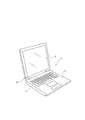
図1は本発明の電子機器の一例を示す斜視図である。図2〜図5は本発明のチルトヒンジの一例を示す図である。図6は本発明のチルトヒンジの他の例を示す図である。本発明に係るチルトヒンジは、ノート型パソコン、携帯電話機、カーナビゲーション装置等の小型の電子機器に取り付けられるものである。以下の例は、本発明に係るチルトヒンジを、例えば、図1に示すように、ノート型パソコン1に取り付けた場合であり、これに限定されるものではない。このノート型パソコン1は、キーボード3、マザーボード、ハードディスクドライブ、フロッピーディスクドライブ等を有する機器本体2に、液晶パネルを有するディスプレイ装置4が開閉可能に取り付けられている。ディスプレイ装置4の機器本体2への取付は、ディスプレイ装置4の開閉を多少のトルクをもって緩やかに行うことができると共に、ディスプレイ装置4が機器本体2に対して任意の角度で保持し得るように本発明のチルトヒンジ5(チルト機構ということがある。)が用いられている。チルトヒンジ5の個数は、電子機器に応じて任意に決められるが、図示例のノート型パソコン1では2個である。
FIG. 1 is a perspective view showing an example of an electronic apparatus of the present invention. 2-5 is a figure which shows an example of the tilt hinge of this invention. FIG. 6 is a view showing another example of the tilt hinge of the present invention. The tilt hinge according to the present invention is attached to a small electronic device such as a notebook computer, a mobile phone, or a car navigation device. The following example is a case where the tilt hinge according to the present invention is attached to a notebook personal computer 1 as shown in FIG. 1, for example, and is not limited thereto. In the notebook personal computer 1, a
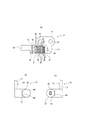
本発明のチルトヒンジ5は、第1の部材と第2の部材を互いに回動可能に連結するヒンジである。このチルトヒンジ5は、図2〜図6に示すように、第1の部材である機器本体2に取り付けられ、板ばね収容部15を有するホルダー10と、第2の部材であるディスプレイ装置4が取り付けられ、板ばね収容部15に回転可能に支持されるシャフト20と、板ばね収容部15内に収容され、ホルダー10又はシャフト20が回動するとき、フリクショントルクを発生させる複数枚のフリクショントルク部材30とを備え、板ばね収容部15に、板ばね収容部15に収容された全枚数又はその一部の枚数のフリクショントルク部材30を外部より視認可能な切欠部41を設けたことを特徴とする。なお、ホルダー10が機器本体2に取り付けられていると共に、ディスプレイ装置4がシャフト20に取り付けられているが、機器本体2にシャフト20を取り付けると共にディスプレイ4をホルダー10に取り付けるようにしてもよい。
The
ホルダー10は、機器本体2にネジ、ボルト等の取付部材13によって取り付けられる取付部11と、その取付部11に一体的に設けられている板ばね収容部15とからなる。取付部11は、亜鉛ダイキャスト製で例えば略矩形板状に形成されている。取付部11には、ネジ、ボルト等の取付部材13を挿通させるための取付孔12が1つ又は2つ以上図示例では2つ設けられている。取付孔12は、予め取付部11に設けてもよいし、また、取付部材13を挿通させるときに設けるようにしてもよい。
The
板ばね収容部15は、シャフト20を回転可能に支持すると共に、複数枚のフリクショントルク部材30を収容するものである。板ばね収容部15は、例えば、取付部11の一角部近傍に一体的に立設されている。板ばね収容部15には、シャフト20を回転可能に支持する断面円形の軸受孔16が設けられている。また、板ばね収容部15には、フリクショントルク部材30を収容するトルク部材収容部40が設けられている。
The leaf
トルク部材収容部40は、例えばフリクショントルク部材30を構成するフリクションディスクや皿ばねが2枚以上例えば合計18枚収容し得る寸法で形成されている。トルク部材収容部40は、軸受孔16と同軸であって軸受孔16より径が大きい円形部40aと、その円形部40aの取付部11側に設けられた略台形状の台形部40bとからなる。
The torque
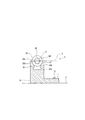
トルク部材収容部40の円形部40aであって取付部11とは反対側の個所に、トルク部材収容部40に収容されたフリクショントルク部材30の一部を外部より視認し得る切欠部41が設けられている。この切欠部41が本発明の特徴とする部分である。すなわち、切欠部41が設けられているトルク部材収容部40は、略凹状に形成されている。切欠部41は、トルク部材収容部40に収容される全枚数のフリクショントルク部材30の一部を外部より視認し得るように形成してもよいし、また、トルク部材収容部40に収容される一部の枚数のフリクショントルク部材30の一部を外部より視認し得るように形成してもよい。切欠部41は、例えば図示するようにトルク部材収容部40がフリクションディスクや皿ばねが合計18枚収容し得る場合にはその18枚のフリクショントルク部材30のうちの16枚分が位置される個所に形成されていてもよい。切欠部41の形状は、トルク部材収容部40に収容されるフリクションディスクや皿ばね等のフリクショントルク部材30が外部より目視できれば特に限定されず、例えば、円弧状、半円状等でもよく、図示例では半円状である。
A
また、切欠部41には、図6に示すように、カバー50が取り付けられていてもよい。カバー50は、特に限定されないが、切欠部41の形状に応じて形成されることが好ましく、例えば半円筒状に形成されている。このカバー50は、トルク部材収容部40の円形部40aの外径と略同じ寸法の外径で、かつその円形部40aの内径と略同じ寸法の内径で形成されている。このカバー50を切欠部41に取り付けることにより、カバー50と切欠部41とによって円筒状の収容部が形成されることになる。カバー50は、例えば合成樹脂により形成されるが、合成樹脂以外の金属材料で構成しても良い。
Further, a
また、カバー50は、切欠部41に着脱可能に取り付けられていることが好ましい。カバー50の切欠部41への取付は、着脱可能であれば特に限定されず、例えば、図7及び図8に示すように、カバー50の切欠部41に接する両接触面50aに、その接触面50aから接触面50aに対して直交方向(略直交方向を含む)に延び先端部が内表面方向に曲った鉤状の係止部51を設けると共に、切欠部41を設けたトルク部材収容部40の両側部41aに係止部51と係合する係合部42を設けるようにしてもよい。これらの係止部51及び係合部42は、例えば、カバー50の長手方向の全体及び両側部41aの長手方向の全体にそれぞれ設けられている。
Moreover, it is preferable that the
また、係止部51は、可撓可能に形成されていることが好ましい。このようにカバー50を可撓可能に形成する場合には、切欠部41へのカバー50の取付は、カバー50の係止部51を切欠部41の係合部42にスライドさせて係合させることにより行う(スライド式によって行う)ようにしてもよいし、また、カバー50の接触面50aと切欠部41の両側部41aとを突き合わせて係止部51を可撓させて行う(押圧式によって行う)ようにしてもよい。また、カバー50を可撓可能に形成する場合には、係止部51及び係合部42は、カバー50の一部及び切欠部41の一部の1箇所又は2箇所以上に設けるようにしてもよい。また、係止部51の代わりに係合突起をカバー50に設けると共に、両側部41aにその係合突起と係合する係合凹部を設けるようにしてもよい。
Moreover, it is preferable that the latching | locking
シャフト20は、板ばね収容部15の軸受孔16に回転可能に支持されると共に、ディスプレイ装置4が取り付けられるものであり、SUS等の丸棒を切削加工等により形成される。シャフト20は、図4及び図5に示すように、フリクショントルク部材30が装着される部分及び前記の軸受孔16が位置される個所は変形部21として形成されている。変形部21は、円形状の対向する2箇所を直線状に切り欠いた略断面楕円形状(太鼓を側面から見た形状)に形成されている。シャフト20の変形部21以外の両端部は、例えば断面円形状に形成されている。このシャフト20の両端部の周面には、例えば、ネジ溝が螺設されている。
The
このシャフト20の第1端部(シャフト20を軸受孔16に支持させたとき軸受孔16を基準としてトルク部材収容部40とは反対側の端部)には、ディスプレイ装置4が取り付けられる取付部材60が設けられている。この取付部材60は、特に限定されないが、例えば、略半円柱状に形成されている。この取付部材60には、ディスプレイ装置4が取り付けられるように取付孔61が設けられていると共にフランジ部62が設けられている。
A mounting member to which the
フリクショントルク部材30は、ホルダー10又はシャフト20が回動(又は回転)するとき、フリクショントルクを発生させるものである。フリクショントルク部材30は、図2〜図5に示すように、例えば、シャフト20の軸方向に移動可能で、かつ、そのシャフト20と共に回動しない第1フリクションディスク31と、その第1フリクションディスク31と隣接して設けられ、シャフト20と共に一体的に回動し、かつ、そのシャフト20の軸方向に移動可能な第2フリクションディスク32と、第1フリクションディスク31及び第2フリクションディスク32の少なくとも一方を対向する第2フリクションディスク32及び/又は第1フリクションディスク31に押し付ける押圧手段35とからなる。
The
第1フリクションディスク31は、例えば、硬質の耐摩耗性に優れた金属材料で形成されたワッシャーやOリング等である。第1フリクションディスク31は、板状であって、例えば、トルク部材収容部40の空洞を区画形成する形状より若干小さな形状に形成されている。すなわち、第1フリクションディスク31は、フリクション発生部である円形ディスク31aと係止部である台形ディスク31bとを有し、トルク部材収容部40に嵌合され得るように形成されている。また、第1フリクションディスク31には、シャフト20が挿通されるシャフト円形孔31cが設けられている。このシャフト円形孔31cは、シャフト20の変形部21の円形状の径と同じか若干大きな寸法の円形に形成されている。また、第1フリクションディスク31の円形ディスク31aの上縁(台形部と対向する個所)には、切欠によって形成されたオイル溜部31dが形成されていることが好ましい。なお、オイル溜部31dを第1フリクションディスク31に設ける位置、数、形態については、実施の形態のものに限定されない。それはシャフト円形孔31cの内周に設けられる場合や、円形ディスク31aに小孔や凹部として設けられる場合がある。
The
第2フリクションディスク32は、例えば、硬質の耐摩耗性に優れた金属材料で形成されたワッシャーやOリング等である。第2フリクションディスク32は、板状であって、例えば、トルク部材収容部40の円形部40aより小さな寸法の径の円形状に形成されている。すなわち、第2フリクションディスク32は、円盤状であってトルク部材収容部40の円形部40aに弛挿され得るように形成されている。また、第2フリクションディスク32には、シャフト20が挿通されるシャフト変形孔32cが設けられている。このシャフト変形孔32cは、第2フリクションディスク32がシャフト20と一体的に回動し得るようにシャフト20の変形部21と同じか若干大きな寸法に形成されている。また、シャフト変形孔32cにはオイル溜部32dが形成されていることが好ましい。
The
押圧手段35は、第1フリクションディスク31及び第2フリクションディスク32の少なくとも一方を対向する第2フリクションディスク32及び/又は第1フリクションディスク31に押し付けるもので、このように押し付けることができるならば特に限定されない。押圧手段35は、例えば、弾性部材とシャフト20の第2端部に取り付けられる締結部材とからなる。
The pressing means 35 is for pressing at least one of the
弾性部材は、特に限定されず、皿ばね36やスプリングワッシャー等であり、例えば皿ばね36である。皿ばね36は、外周部が湾曲して皿状であって、トルク部材収容部40の円形部40aより径が小さい略円盤状に形成されている。また、皿ばね36には、シャフト20が挿通される円形状のシャフト孔が設けられている。この皿ばね36、第1及び第2フリクションディスク31、32のシャフト20への装着枚数や配置は、径方向の長さを短くしてもフリクショントルクを発生させることができるならば特に限定されず、例えば、トルク部材収容部40に軸受孔16から近い順に第1フリクションディスク31、第2フリクションディスク32、2枚の皿ばね36、第2フリクションディスク32、第1フリクションディスク31、第2フリクションディスク32、2枚の皿ばね36、第2フリクションディスク32、第1フリクションディスク31、第2フリクションディスク32、第1フリクションディスク31、第2フリクションディスク32、第1フリクションディスク31、第2フリクションディスク32、第1フリクションディスク31、第2フリクションディスク32が収容され、かつ、トルク部材収容部40の外側に5枚の皿ばね36が配置されるようにしてもよい。
The elastic member is not particularly limited, and is a
締結部材は、皿ばね36や第1、第2フリクションディスク31、32を圧接して皿ばね36の弾性力等によって第1フリクションディスク31と第2フリクションディスク32等を密着させ、シャフト20が回動(又は回転)したときに、シャフト20の回動と共に回動する第2フリクションディスク32と第1フリクションディスク31との間にスラスト方向の摩擦力を発生させてフリクショントルクを発生させるものである。締結部材としては、例えば、シャフト20の第2端部に螺合されるナットやシャフト20の第2端部に加締めて取り付けられる押え用ワッシャー37等が挙げられ、図示例では押え用ワッシャー37である。押え用ワッシャー37は、SUS等の鋼板で、フリクションディスク31、32より厚さが厚い円盤状に形成されている。押え用ワッシャー37には、シャフト20が挿通し得るシャフト孔が設けられている。
The fastening member presses the
次に本発明のチルトヒンジ5を組み付ける場合について説明する。
まず、シャフト20のフランジ部62側に第2フリクションディスク32を圧入し、ホルダー10の凹部17に第1フリクションディスク31を入れ、シャフト20をホルダー10の軸受孔16に通してからトルク部材収容部40に収容される個所のシャフト20の変形部21の外周に順次第1フリクションディスク31、第2フリクションディスク32、2枚の皿ばね36、第2フリクションディスク32、第1フリクションディスク31、第2フリクションディスク32、2枚の皿ばね36、第2フリクションディスク32、第1フリクションディスク31、第2フリクションディスク32、第1フリクションディスク31、第2フリクションディスク32、第1フリクションディスク31、第2フリクションディスク32、第1フリクションディスク31、第2フリクションディスク32が重なり合うように位置させる。この場合、第1フリクションディスク31は、そのシャフト円形孔31cにシャフト20を挿通して第1フリクションディスク31をシャフト20に対してスライドすることにより位置決めが行われる。同様に第2フリクションディスク32は、そのシャフト変形孔32cにシャフト20を挿通して第2フリクションディスク32をシャフト20に対して圧入することにより位置決めが行われ、皿ばね36は、そのシャフト孔にシャフト20を挿通して皿ばね36をシャフト20に対してスライドすることにより位置決めが行われる。これにより、シャフト20の変形部21の外周に合計18枚のフリクショントルク部材30が位置される。
Next, the case where the
First, the
次にこの18枚のフリクショントルク部材30を有するシャフト20をホルダー10に装着する。ホルダー10への装着は、シャフト20の第1端部をトルク部材収容部40側から軸受孔16に挿入して貫通させ、シャフト20の外周に位置される18枚のフリクショントルク部材30をトルク部材収容部40にスライドさせて収容する。このとき、トルク部材収容部40に切欠部41を設けたことにより、全枚数又はその一部の枚数のフリクショントルク部材30はその一部が外部より視認可能な状態でトルク部材収容部40に収容されるので、トルク部材収容部40内に収容されているフリクショントルク部材30を目視することができる。このため、組み付け中にトルク部材収容部40内に収容するフリクショントルク部材30を確認しながら、フリクショントルク部材30をトルク部材収容部40内に収容することができるので、トルク部材収容部40内に収容するフリクショントルク部材30の枚数や組み合わせを間違えることなく行える。
Next, the
また、トルク部材収容部40に切欠部41が設けられているために、フリクショントルク部材30をトルク部材収容部40の所定の位置にスライドするとき、フリクショントルク部材30の縁部がトルク部材収容部40の内壁に接触することもあり得る。
Further, since the
なお、カバー50をトルク部材収容部40の切欠部41にスライド式に取り付ける場合には、カバー50の取付は、シャフト20にホルダー10を装着した後に行ってもよい。また、カバー50の切欠部41への取付がスライド式ではなく押圧式である場合には、カバー50の取付は特に限定されない。
When the
そして、シャフト20の第2端部から例えば5枚の皿ばね36を装着して、これらの皿ばね36をトルク部材収容部40に収容されている一番外側の第2フリクションディスク32に重ね合わせる。皿ばね36装着後、シャフト20の第2端部に例えば押え用ワッシャー37を加締めて取り付けることにより、本発明のチルトヒンジ5が組み付けられる。このように本発明のチルトヒンジ5は、径方向の長さを短くしてもトルク部材収容部40に例えば18枚のフリクショントルク部材30を収容させて必要なフリクショントルクを創出できるので、小型の電子機器、特にノート型パソコン1に適したものである。
Then, for example, five disc springs 36 are mounted from the second end portion of the
押え用ワッシャー37の取付は、皿ばね36とフリクションディスク31、32とが圧接されて、例えばシャフト20がホルダー10に対して回動するとき、皿ばね36とフリクションディスク31、32との接触面にスラスト方向の摩擦力が発生してフリクショントルクが発生するようにする。押え用ワッシャー37の加締める力を代えることによりフリクショントルク力を任意に代えることが可能である。なお、押え用ワッシャーの代わりにナットを用いる場合にはナットのシャフトに対する位置を代えることによりフリクショントルク力を任意に代えることが可能である。
The
したがって、本発明のチルトヒンジ5は、トルク部材収容部40に切欠部41が設けられているために、板ばね収容部15のトルク部材収容部40内に収容されるフリクショントルク部材30を外部より目視することができる。その結果、トルク部材収容部40内に収容するフリクショントルク部材30の枚数や組み合わせを間違えることなく行え、歩留まりが向上すると共に、組み付け作業を容易行えることになる。
Accordingly, since the
また、カバー50が切欠部41に取り付けられていても、カバー50を取り外したりすることにより、略同様にフリクショントルク部材30を確認することができ、トルク部材収容部40内に収容するフリクショントルク部材30の枚数や組み合わせを間違えることなく行えると共に組み付け作業が容易となる。
Even if the
この本発明のチルトヒンジ5のホルダー10を例えばノート型パソコン1の機器本体2に取り付けると共に、シャフト20の取付部材60にディスプレイ装置4を取り付ける。この取付を行うとき、板ばね収容部15のトルク部材収容部40に切欠部41が設けられていることにより、トルク部材収容部40内に収容されているフリクショントルク部材30を視認することができるので、確実に機器本体2とディスプレイ装置4とを必要なフリクショントルクをもって回動可能に連結することができる。すなわち、チルトヒンジ5のトルク部材収容部40内に収容されているフリクショントルク部材30の枚数や組み合わせを視認できるので、もしそのフリクショントルク部材30の枚数や組み合わせが間違っている場合には、フリクショントルク部材30の枚数や組み合わせが間違ってない別のチルトヒンジ5を用いて機器本体2にディスプレイ装置4を取り付けることができるので、確実に機器本体2とディスプレイ装置4とを必要なフリクショントルクをもって回動可能に連結することができ、歩留まりが向上する。
The
これにより、ディスプレイ装置4を開閉したとき、シャフト20がホルダー10に対して回動して、フリクションディスク31、32の接触面にスラスト方向の摩擦力が発生してフリクショントルクが発生する。すなわち、押え用ワッシャー37によって、皿ばね36や第1、第2フリクションディスク31、32が圧接されて皿ばね36の弾性力等によって第1フリクションディスク31と第2フリクションディスク32等が密着する。この状態でシャフト20が回動したとき、シャフト20の回動と共に回動する第2フリクションディスク32と第1フリクションディスク31との間にスラスト方向の摩擦力が発生してフリクショントルクが発生する。その結果、ディスプレイ4の開閉を多少のトルクをもって緩やかに行うことができる。また、ディスプレイ4の開閉を止めると、ディスプレイ4はフリクショントルクによってその状態に保持されるので、ディスプレイ4を機器本体2に対して任意の角度で保持することができる。
Thus, when the
板ばね収容部内に収容されるフリクショントルク部材を外部より目視することができるので、フリクショントルク部材の枚数や組み合わせを間違えることなく、歩止まりの良い、とくにノート型パソコン等の電子機器用のチルトヒンジを提供できるものである。 Since the friction torque member accommodated in the leaf spring accommodating portion can be visually observed from the outside, a tilt hinge for electronic equipment such as a notebook computer can be obtained with a good yield without making a mistake in the number and combination of the friction torque members. It can be provided.
1 ノート型パソコン
2 機器本体
3 キーボード
4 ディスプレイ
5 チルトヒンジ
10 ホルダー
11 取付部
15 板バネ収容部
17 第2収容部
20 シャフト
21 変形部
30 フリクショントルク部材
31 第1フリクションディスク
32 第2フリクションディスク
35 押圧手段
36 皿ばね
37 押え用ワッシャー
40 トルク部材収容部
41 切欠部
42 係合部
50 カバー
51 係止部
60 取付部材
DESCRIPTION OF SYMBOLS 1 Notebook personal computer 2 Apparatus
Claims (4)
前記第1の部材又は前記第2の部材のいずれか一方に取り付けられ、板ばね収容部を有するホルダーと、
前記第1の部材又は前記第2の部材の残りの他方に取り付けられ、前記板ばね収容部に回転可能に支持されるシャフトと、
前記板ばね収容部内に収容され、前記ホルダー又は前記シャフトが回動するとき、フリクショントルクを発生させる複数枚のフリクショントルク部材とを備えたものにおいて、
前記板ばね収容部に、該板ばね収容部に収容された前記全枚数又はその一部の枚数のフリクショントルク部材を外部より視認可能な切欠部を設けたことを特徴とするチルトヒンジ。 A hinge for connecting the first member and the second member to each other so as to be rotatable;
A holder attached to either one of the first member or the second member and having a leaf spring accommodating portion;
A shaft attached to the other one of the first member or the second member and rotatably supported by the leaf spring accommodating portion;
In the one provided with a plurality of friction torque members that are contained in the leaf spring accommodating portion and generate friction torque when the holder or the shaft rotates,
2. A tilt hinge according to claim 1, wherein the leaf spring accommodating portion is provided with a notch portion from which the entire or a part of the number of friction torque members accommodated in the leaf spring accommodating portion can be visually recognized.
Priority Applications (5)
| Application Number | Priority Date | Filing Date | Title |
|---|---|---|---|
| JP2004224748A JP2006046384A (en) | 2004-07-30 | 2004-07-30 | Tilt hinge and electronic device having the same |
| TW094124192A TWI290982B (en) | 2004-07-30 | 2005-07-15 | Tilt hinge and electronic device with the same |
| KR1020050067324A KR100631376B1 (en) | 2004-07-30 | 2005-07-25 | tilt hinge and electronic apparatus with the tilt hinge |
| US11/189,938 US20060032022A1 (en) | 2004-07-30 | 2005-07-26 | Tilt hinge and electronic apparatus using the same |
| CN200510088907.9A CN1727704A (en) | 2004-07-30 | 2005-08-01 | Tilt hinge and electronic apparatus using the same |
Applications Claiming Priority (1)
| Application Number | Priority Date | Filing Date | Title |
|---|---|---|---|
| JP2004224748A JP2006046384A (en) | 2004-07-30 | 2004-07-30 | Tilt hinge and electronic device having the same |
Publications (1)
| Publication Number | Publication Date |
|---|---|
| JP2006046384A true JP2006046384A (en) | 2006-02-16 |
Family
ID=35798548
Family Applications (1)
| Application Number | Title | Priority Date | Filing Date |
|---|---|---|---|
| JP2004224748A Pending JP2006046384A (en) | 2004-07-30 | 2004-07-30 | Tilt hinge and electronic device having the same |
Country Status (5)
| Country | Link |
|---|---|
| US (1) | US20060032022A1 (en) |
| JP (1) | JP2006046384A (en) |
| KR (1) | KR100631376B1 (en) |
| CN (1) | CN1727704A (en) |
| TW (1) | TWI290982B (en) |
Families Citing this family (12)
| Publication number | Priority date | Publication date | Assignee | Title |
|---|---|---|---|---|
| US20070157433A1 (en) * | 2006-01-09 | 2007-07-12 | Shin Zu Shing Co., Ltd. | Positioning hinge |
| JP2007205538A (en) * | 2006-02-06 | 2007-08-16 | Shimonishi Giken Kogyo Kk | Tilt hinge |
| US7685679B2 (en) * | 2007-07-03 | 2010-03-30 | Jamie Horng | Pivotal hinge with an oil-retaining collar |
| TW200914745A (en) * | 2007-09-21 | 2009-04-01 | Chen Ching Yau | Structure and manufacturing method of combination-type male hinge |
| US20120124775A1 (en) * | 2010-11-19 | 2012-05-24 | Ceci Victor A | Friction hinge with closed clips |
| CN103363466B (en) * | 2012-03-26 | 2016-12-14 | 海洋王照明科技股份有限公司 | Lamp casing and Varied clearance hinge |
| CN103362947B (en) * | 2012-03-27 | 2016-09-07 | 海洋王照明科技股份有限公司 | Hinge arrangement and use the lighting device of this hinge arrangement |
| TWI498496B (en) * | 2012-11-15 | 2015-09-01 | Kinpo Elect Inc | Damper and multifunction printer using the same |
| US9234375B1 (en) * | 2014-10-06 | 2016-01-12 | Chin-Hsing Horng | Hinge structure with male shaft position adjustability |
| JP2021195998A (en) * | 2020-06-15 | 2021-12-27 | 株式会社ナチュラレーザ・ワン | Support mechanism, and support device with the support mechanism |
| TWI770650B (en) * | 2020-09-01 | 2022-07-11 | 仁寶電腦工業股份有限公司 | Hinge structure |
| US11952128B2 (en) | 2022-04-05 | 2024-04-09 | B/E Aerospace, Inc. | Aircraft seat arm O-ring friction mechanism |
Family Cites Families (9)
| Publication number | Priority date | Publication date | Assignee | Title |
|---|---|---|---|---|
| US3831452A (en) * | 1973-01-08 | 1974-08-27 | Wheatley C Inc | Gas sampler |
| US5940936A (en) * | 1998-07-02 | 1999-08-24 | Lu; Sheng-Nan | Pivot device for use with a monitor |
| US6192561B1 (en) * | 1998-12-16 | 2001-02-27 | Ronald B. Bennett | Cartridge case former and method |
| US6256838B1 (en) * | 2000-01-25 | 2001-07-10 | Lu Sheng-Nan | Pivoting assembly for a notebook computer |
| KR200233484Y1 (en) * | 2001-02-22 | 2001-09-28 | 피케이텍시스템 주식회사 | Hinge Device |
| US6671928B2 (en) * | 2001-05-23 | 2004-01-06 | Kuo-Cheng Huang | Hinge assembly for monitor |
| KR100463524B1 (en) * | 2002-05-29 | 2004-12-29 | 엘지전자 주식회사 | Hinge assembly for video display appliance |
| JP2004138129A (en) * | 2002-10-16 | 2004-05-13 | Kato Electrical Mach Co Ltd | Tilt hinge |
| TWM247160U (en) * | 2003-12-03 | 2004-10-21 | Ching Feng Home Fashions Co | Shower screen shield |
-
2004
- 2004-07-30 JP JP2004224748A patent/JP2006046384A/en active Pending
-
2005
- 2005-07-15 TW TW094124192A patent/TWI290982B/en not_active IP Right Cessation
- 2005-07-25 KR KR1020050067324A patent/KR100631376B1/en not_active IP Right Cessation
- 2005-07-26 US US11/189,938 patent/US20060032022A1/en not_active Abandoned
- 2005-08-01 CN CN200510088907.9A patent/CN1727704A/en active Pending
Also Published As
| Publication number | Publication date |
|---|---|
| TWI290982B (en) | 2007-12-11 |
| KR100631376B1 (en) | 2006-10-04 |
| TW200604448A (en) | 2006-02-01 |
| KR20060046745A (en) | 2006-05-17 |
| US20060032022A1 (en) | 2006-02-16 |
| CN1727704A (en) | 2006-02-01 |
Similar Documents
| Publication | Publication Date | Title |
|---|---|---|
| KR100631376B1 (en) | tilt hinge and electronic apparatus with the tilt hinge | |
| US20080158809A1 (en) | Computer enclosure incorporating drive bracket | |
| US6882527B2 (en) | Computer enclosure incorporating drive bracket | |
| KR100942855B1 (en) | A brushless motor and a disk drive mounting the same | |
| EP1967748A1 (en) | Two-axis hinge device with rotation regulating function | |
| US20090235489A1 (en) | Sheath Type Rotating Axel Structure with Automatic Locking Mechanism | |
| KR20040034405A (en) | tilt hinge | |
| JP2005106139A (en) | Tilt hinge | |
| US20060290246A1 (en) | Rotating machanism of drive bracket | |
| US20130127318A1 (en) | Clamshell device | |
| JP2008020033A (en) | Tilt hinge and electronic equipment | |
| US6249951B1 (en) | Hinge structure for electronic apparatus | |
| WO2015045131A1 (en) | Electronic apparatus and hinge unit | |
| US7690084B2 (en) | Structure of anti-vibrating rotation shaft | |
| US20110102982A1 (en) | Electronic apparatus | |
| TWI491810B (en) | Electronic device and tilt hinge thereof | |
| JP4951110B2 (en) | TV, electronics | |
| JP2009180368A (en) | Small hinge, and small electronic equipment using the same | |
| JP5584149B2 (en) | Electronics | |
| JP2007205538A (en) | Tilt hinge | |
| JP6061460B2 (en) | Biaxial hinge and electronic device provided with the biaxial hinge | |
| JP2003156029A (en) | Tilt hinge manufacturing method, tilt hinge, and information processor | |
| JP2008256178A (en) | Tilt hinge and electronic equipment | |
| JP2006189135A (en) | Hinge device | |
| JP2006083897A (en) | Tilt hinge |
Legal Events
| Date | Code | Title | Description |
|---|---|---|---|
| A621 | Written request for application examination |
Free format text: JAPANESE INTERMEDIATE CODE: A621 Effective date: 20070725 |
|
| A977 | Report on retrieval |
Free format text: JAPANESE INTERMEDIATE CODE: A971007 Effective date: 20090828 |
|
| A131 | Notification of reasons for refusal |
Free format text: JAPANESE INTERMEDIATE CODE: A131 Effective date: 20090908 |
|
| A02 | Decision of refusal |
Free format text: JAPANESE INTERMEDIATE CODE: A02 Effective date: 20100112 |