EP4389986B1 - Commande d'une opération d'excavation sur la base d'une détection de charge - Google Patents
Commande d'une opération d'excavation sur la base d'une détection de charge Download PDFInfo
- Publication number
- EP4389986B1 EP4389986B1 EP22215077.3A EP22215077A EP4389986B1 EP 4389986 B1 EP4389986 B1 EP 4389986B1 EP 22215077 A EP22215077 A EP 22215077A EP 4389986 B1 EP4389986 B1 EP 4389986B1
- Authority
- EP
- European Patent Office
- Prior art keywords
- end effector
- conversion rule
- resistance
- design surface
- excavator
- Prior art date
- Legal status (The legal status is an assumption and is not a legal conclusion. Google has not performed a legal analysis and makes no representation as to the accuracy of the status listed.)
- Active
Links
Images

Classifications
-
- E—FIXED CONSTRUCTIONS
- E02—HYDRAULIC ENGINEERING; FOUNDATIONS; SOIL SHIFTING
- E02F—DREDGING; SOIL-SHIFTING
- E02F3/00—Dredgers; Soil-shifting machines
- E02F3/04—Dredgers; Soil-shifting machines mechanically-driven
- E02F3/28—Dredgers; Soil-shifting machines mechanically-driven with digging tools mounted on a dipper- or bucket-arm, i.e. there is either one arm or a pair of arms, e.g. dippers, buckets
- E02F3/36—Component parts
- E02F3/42—Drives for dippers, buckets, dipper-arms or bucket-arms
- E02F3/43—Control of dipper or bucket position; Control of sequence of drive operations
- E02F3/435—Control of dipper or bucket position; Control of sequence of drive operations for dipper-arms, backhoes or the like
- E02F3/437—Control of dipper or bucket position; Control of sequence of drive operations for dipper-arms, backhoes or the like providing automatic sequences of movements, e.g. linear excavation, keeping dipper angle constant
-
- E—FIXED CONSTRUCTIONS
- E02—HYDRAULIC ENGINEERING; FOUNDATIONS; SOIL SHIFTING
- E02F—DREDGING; SOIL-SHIFTING
- E02F3/00—Dredgers; Soil-shifting machines
- E02F3/04—Dredgers; Soil-shifting machines mechanically-driven
- E02F3/28—Dredgers; Soil-shifting machines mechanically-driven with digging tools mounted on a dipper- or bucket-arm, i.e. there is either one arm or a pair of arms, e.g. dippers, buckets
- E02F3/36—Component parts
- E02F3/42—Drives for dippers, buckets, dipper-arms or bucket-arms
- E02F3/43—Control of dipper or bucket position; Control of sequence of drive operations
- E02F3/435—Control of dipper or bucket position; Control of sequence of drive operations for dipper-arms, backhoes or the like
- E02F3/439—Automatic repositioning of the implement, e.g. automatic dumping, auto-return
-
- E—FIXED CONSTRUCTIONS
- E02—HYDRAULIC ENGINEERING; FOUNDATIONS; SOIL SHIFTING
- E02F—DREDGING; SOIL-SHIFTING
- E02F9/00—Component parts of dredgers or soil-shifting machines, not restricted to one of the kinds covered by groups E02F3/00 - E02F7/00
- E02F9/26—Indicating devices
- E02F9/264—Sensors and their calibration for indicating the position of the work tool
Definitions
- the present invention relates to automation and/or operator assistance in an excavation operation to obtain a design surface.
- Excavators are often equipped with automation and assistance systems configured to assist the operator in order to generate a finished surface.
- assistance systems are configured to restrict or remap input commands for moving the end effector as a function of the geometry of the design surface (and the excavator positioning).
- the assistance system may be configured to enforce parallel movements of the end effector relative to the ground or relative to the design surface.
- the use of the assistance system is limited to operating very near to a design surface, such that the operator is only assisted during the final pass.
- Gross excavation to remove the material above grade has to be executed manually, which, for example, could still provoke digging into/below the design surface.
- this is because existing systems often operate in a so-called kinematic capacity, wherein the operation is based on the position and trajectory of the end effector.
- a purely-kinematic assistance system cannot account for material interaction, which largely dictates the required motion during gross excavation.
- an automation and assistance system requiring the operator to perform gross excavation manually, may not be the ideal workflow as the system is inactive for the majority of the excavation.
- Alternative automated digging strategies are based on scanning the surface of the soil and planning a digging pass by using the rated volume of the bucket, the soil surface profile, and algorithmically determined metrics for generating a path that sweeps a desired volume of material.
- WO2005/103396 A1 which relates to a method of estimating parameters of a medium to be moved by a digging apparatus, to a computer program product, to a digging apparatus and to a method of excavating a site.
- a further object is to provide a more efficient excavation while reducing the amount of faulty excavation steps.
- one aspect of the invention relates to providing an automation and assistance system over a larger operating envelope.
- an operator is provided with the option to leverage the automation system during nearly the entirety of a trenching operation.
- the resistance data provide information on forces exerted on the end effector and the directions in which the forces act in relation to at least two, e.g. three, different directions.
- the resistance data provide information on a moment exerted on the end effector, which is caused by the end effector pressing onto the material to be moved and/or by the end effector moving through the material to be moved.
- the first and/or the second conversion rule includes a control of a speed of the end effector as a function of the resistance data.
- the speed at which the end effector is moved along the target path is controlled as a function of the resistance data.
- the speed at which the end effector is moved along a defined spatial direction is controlled as a function of the resistance data.
- the end effector may be controlled to dig more slowly in very tough material.
- a speed requested on the basis of the control commands by the operator is limited, such that the resistance stays below a threshold resistance.
- an automated system may be provided such that in further step, an (e.g. automated) orienting of the end effector into a defined (safe) hold orientation before the releasing of the original assignment of the control commands is carried out.
- Another option is an initiation by a further threshold criterion for a resistance force and/or a resistance moment being exerted on the end effector when it engages material to be moved, e.g. wherein the further threshold criterion indicates that a load has grown too large for the excavator to sustain forward motion.
- the digging efficiency criterion provides at least one of: maximizing power applied by a cut region of the end effector onto material to be moved by the excavator; minimizing path deviation of a path of the end effector; minimizing a resistance force exerted onto the end effector in a defined direction; minimizing a resistance moment exerted onto the end effector; maintaining a target resistance force and/or a target resistance moment exerted on the end effector; and maintaining an orientation of the end effector such that the material to be moved is cut by teeth of the end effector.
- the method comprises a determining of the target path as a path parallel to the design surface at a current penetration depth of the end effector into the material to be moved and a triggering of the first conversion rule when the control commands indicate a movement of the end effector parallel to the design surface.
- the method may include a monitoring of the load data and an automatic detection when the end effector is suitably engaged in the soil. This could then be used to trigger generation of a target path parallel to the design surface at the current depth, and transitioning from manual to automatic control is triggered upon determining that the end effector is suitably engaged in the soil.
- the method comprises a determining of the target path as a path parallel to the design surface at a current penetration depth of the end effector into the material to be moved and a triggering of the first conversion rule based on a monitoring of the resistance data and an engagement criterion as a function of the resistance data.
- the invention further relates to a computer program product comprising program code which is stored on a machine-readable medium, or being embodied by an electromagnetic wave comprising a program code segment, and has computer-executable instructions for performing, in particular when run on a computing unit of a system described above: accessing the design data and the control commands of the steps of accessing design data and control commands as described above; accessing the resistance data of the step of accessing resistance data as described above; providing the first and the second conversion rule according to the steps of providing the first conversion rule and providing the second conversion rule as described above; and evaluating the resistance data to provide the transitioning according to the step of transitioning from the first conversion rule to the second conversion rule as described above.
- program code comprises computer-executable instructions for performing any step in the method as described above.
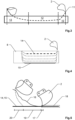
- FIG. 1 shows an exemplary embodiment of an excavator 1, which can be embodied or upgraded to work according to the method described above.
- a computing unit mounted on the excavator 1 has access to a sensor unit configured to provide resistance data indicative of a resistance force exerted on the bucket 2 of the excavator when engaging with material to be moved by the excavator.
- the system may further comprise a perception sensor configured to generate perception data, wherein mounting locations 3A, 3B for the perception sensor may be somewhere on the boom 4 of the excavator and/or on the cabin 5.
- the data recorded by the perception unit are used to evaluate whether the design surface intersects a material surface of the soil.
- the perception unit comprises at least one camera.
- the perception unit comprises a 3D coordinate measuring device, e.g. embodied as a laser scanner.
- the sensor unit provides kinematic information for different parts of the excavator and information regarding the effects of (e.g. external) forces acting on different parts of the bucket 2 when interacting with the soil, e.g. provided by a torque or force sensor monitoring a bucket joint.
- the first and the second conversion rules map control commands for moving parts of the excavator, e.g. a boom 4, a stick 6, a rotating cabin 5, and a bucket joint 7, to specific movements that ensure movement of the bucket according to the first and the second conversion rule, respectively.
- Figure 2 exemplarily indicates possible forces and moments captured by the resistance data when the bucket 2 engages with the soil 8, e.g. a load acting on the bucket 2 from the soil 8 in the x-direction, a load acting on the bucket 2 from the soil 8 in the ⁇ -direction, and a moment 9 (acting on the bucket in the z direction, perpendicular to x and y).
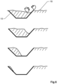
- FIG. 3 schematically depicts an exemplary semi-automatic workflow according to a first embodiment of the inventive method.
- a penetration phase 10 the operator brings the blade 11 of the bucket 2 to the desired depth with the desired attack angle, then initiates semi-automatic digging by pulling in the stick only.
- a scraping phase 12 the operator pulls the stick joystick, wherein the bucket trajectory is automatically controlled by the first conversion rule to follow a horizontal path with maximum digging efficiency, e.g. defined as speed times force equals target digging power.
- the operator raises the boom, curls the bucket, and is given back control of the stick according to the original assignment of the control commands of the excavator.
- the semi-automatic system ensures there is no overdig due to the bucket curl.
- the operator simply executes successive digging passes until the system achieves the desired design surface.
- Figure 4 schematically depicts a second embodiment of the invention, wherein the first conversion rule provides for incrementally digging parallel to the desired design surface.
- the operator positions the cutting edge of the bucket 2 at the start of a cutting pass and penetrates the soil to the desired depth.
- the operator pulls in on the arm command and the first conversion rule ensures that the bucket 2 generates a path following a target path 14 at the desired depth, parallel to the design surface 15.
- the automated system transitions into the second conversion rule and provides lifting of the bucket 2 in an efficient way as a function of a digging efficiency criterion, e.g.
- efficient digging is maximizing power applied in the cut
- efficient digging is optimized to minimize the path deviations due to variations in loading
- efficient digging is optimized to minimize the loads in a given direction
- efficient digging is optimized to maintain the vehicle at a target load level (hydraulic load, engine load, or both)
- efficient digging is optimized so that the load is characteristic of the bucket teeth and ears cutting the soil rather than the cutting edge.
- efficient digging may be using an admittance based control scheme in place of a kinematic control scheme.
- kinematically controlled digging digging according to the first conversion rule
- the desired kinematic path sets the boundary conditions for the path generation to return the bucket from the dump location to the cutting location. It is trivial for the automation system to plan a path from the end of the dig cycle to the desired dump location, so a full dig cycle can now be planned with a typical kinematic method being used everywhere except a loading dependent path during the soil engagement. Since trenching is a largely linear operation, a fully autonomous system can also include simple rules to determine when to advance the tracks along the trench.
Landscapes
- Engineering & Computer Science (AREA)
- Mechanical Engineering (AREA)
- Mining & Mineral Resources (AREA)
- Civil Engineering (AREA)
- General Engineering & Computer Science (AREA)
- Structural Engineering (AREA)
- Life Sciences & Earth Sciences (AREA)
- General Life Sciences & Earth Sciences (AREA)
- Paleontology (AREA)
- Operation Control Of Excavators (AREA)
Claims (15)
- Procédé de commande d'une opération d'excavation par une excavatrice (1) pour obtenir une surface de conception, lequel procédé consiste à :• accéder à des données de conception fournissant des informations de forme et de localisation de la surface de conception (15) et accéder à des instructions de commande pour manoeuvrer un effecteur terminal (2) de l'excavatrice (1),• accéder à des données de résistance indiquant une résistance exercée contre l'effecteur terminal lorsqu'il attaque le matériau à déplacer (8),• fournir une première règle de conversion configurée pour faire correspondre les instructions de commande à des instructions de mouvement pour l'effecteur terminal (2), ce qui amène l'effecteur terminal (2) à se déplacer selon une trajectoire cible (14) dérivée de la surface de conception (15), en particulier dans lequel la trajectoire cible (14) s'étend au moins en sections parallèles à la surface de conception (15),caractérisé en ce que le procédé consiste en outre à :• fournir une seconde règle de conversion configurée pour faire correspondre les instructions de commande à des instructions de mouvement pour l'effecteur terminal (2) en fonction des données de résistance et d'un critère d'efficacité de creusement, dans lequel la seconde règle de conversion est différente de la première règle de conversion et permet de déplacer l'effecteur terminal (2) indépendamment de la trajectoire cible (14), et• passer de la première règle de conversion à la seconde règle de conversion en fonction des données de résistance.
- Procédé selon la revendication 1, dans lequel les données de résistance fournissent des informations sur les forces exercées sur l'effecteur terminal (2) et les directions dans lesquelles les forces agissent par rapport à au moins deux, en particulier trois, directions spatiales différentes.
- Procédé selon l'une des revendications précédentes, dans lequel les données de résistance fournissent des informations sur un moment exercé sur l'effecteur terminal (2), qui est causé par l'effecteur terminal (2) appuyant sur le matériau à déplacer (8) et/ou par l'effecteur terminal (2) se déplaçant à travers le matériau à déplacer (8).
- Procédé selon l'une des revendications précédentes, dans lequel le passage est effectué sur la base d'un critère de seuil pour une force de résistance et/ou un moment de résistance exercé sur l'effecteur terminal (2) lorsqu'il attaque le matériau à déplacer (8) par l'excavatrice,
en particulier dans lequel le critère de seuil est associé à la fourniture d'une précision définie pour suivre la trajectoire cible (14) par l'effecteur terminal (2) selon la première règle de conversion et/ou dans lequel le critère de seuil est associé à la fourniture d'une limite d'une force admissible agissant sur une articulation (7) d'un composant de l'excavatrice qui fournit le mouvement de l'effecteur terminal (2). - Procédé selon l'une des revendications précédentes, comprenant un arrêt de la seconde règle de conversion sur la base d'une instruction de l'utilisateur et/ou en fonction des données de résistance, libérant ainsi une affectation initiale des instructions de commande en instructions de mouvement pour l'effecteur terminal (2),
en particulier comprenant une orientation de l'effecteur terminal (2) dans une orientation de maintien définie avant la libération de l'affectation initiale des instructions de commande. - Procédé selon la revendication 5, dans lequel l'arrêt de la seconde règle de conversion est déclenché par au moins l'un des faits suivants :• les instructions de commande indiquent un mouvement d'enroulement défini de l'effecteur terminal (2),• la reconnaissance du fait que les données de résistance indiquent que l'effecteur terminal (2) est soulevé hors du matériau à déplacer (8) par l'excavatrice, particulièrement indiqué par une chute soudaine d'une force de résistance et/ou une chute soudaine d'un moment de résistance exercé sur l'effecteur terminal (2),• un historique des données de résistance d'une passe actuelle de l'effecteur terminal (2) et un critère de fin de passe qui indique, en fonction de l'historique des données de résistance, que la passe actuelle a atteint une progression définie, et• un autre critère de seuil pour une force de résistance et/ou un moment de résistance exercés sur l'effecteur terminal (2) lorsqu'il attaque le matériau à déplacer (8).
- Procédé selon l'une des revendications précédentes, dans lequel le critère d'efficacité de creusement fournit au moins l'un des résultats suivants :• maximiser la puissance appliquée par une zone de coupe (11) de l'effecteur terminal (2) sur le matériau à déplacer (8) par l'excavatrice,• minimiser la déviation de trajectoire de l'effecteur terminal (2),• minimiser une force de résistance exercée sur l'effecteur terminal (2) dans une direction définie,• minimiser un moment de résistance exercé sur l'effecteur terminal (2),• maintenir une force de résistance cible et/ou un moment de résistance cible exercés sur l'effecteur terminal (2), et• maintenir une orientation de l'effecteur terminal (2) de telle sorte que le matériau à déplacer (8) soit coupé par les dents de l'effecteur terminal (2).
- Procédé selon l'une des revendications précédentes, dans lequel, selon la première règle de conversion, la trajectoire cible (14) est modifiée de manière séquentielle, fournissant ainsi une séquence de trajectoires cibles (14) à excaver l'une après l'autre, dans lequel la séquence est dérivée de la surface de conception (15) et s'approche par incréments de la surface de conception (15), en particulier dans lequel chacune des différentes trajectoires cibles (14) s'étend au moins dans certaines sections parallèlement à la surface de conception (15).
- Procédé selon l'une des revendications précédentes, comprenant une détermination de la trajectoire cible (14) en tant que trajectoire parallèle à la surface de conception (15) à une profondeur de pénétration actuelle de l'effecteur terminal (2) dans le matériau à déplacer (8) et• un déclenchement de la première règle de conversion lorsque les instructions de commande indiquent un mouvement de l'effecteur terminal (2) parallèle à la surface de conception (15), et/ou• un déclenchement de la première règle de conversion sur la base d'une surveillance des données de résistance et d'un critère d'attaque en fonction des données de résistance.
- Procédé selon l'une des revendications 1 à 7, dans lequel, selon la première règle de conversion, la trajectoire cible (14) se situe dans la surface de conception (15),
en particulier dans lequel, dans le cas où la surface de conception (15) croise une surface de matériau (16) du matériau à déplacer (8) par l'excavatrice, une passe d'excavation est lancée en activant la première règle de conversion, de sorte que le premier contact de l'effecteur terminal (2) avec le matériau à déplacer (8) est établi en un point de la surface de conception (15). - Système de commande d'une opération d'excavation par un effecteur terminal (2) d'une excavatrice (1) pour obtenir une surface de conception (15), dans lequel le système est configuré pour mettre en œuvre le procédé selon l'une des revendications 1 à 10, pour lequel il comprend une unité de calcul configurée :• pour accéder aux données de conception et aux instructions de commande des étapes consistant à accéder aux données de conception et aux instructions de commande selon la revendication 1,• pour accéder aux données de résistance de l'étape consistant à accéder aux données de résistance selon la revendication 1,• pour fournir la première et la seconde règle de conversion selon les étapes consistant à fournir la première règle de conversion et à fournir la seconde règle de conversion selon la revendication 1, et• pour évaluer les données de résistance pour effectuer le passage selon l'étape consistant à passer de la première règle de conversion à la seconde règle de conversion.
- Système selon la revendication 11, comprenant une unité de détection configurée pour être montée sur une excavatrice (1) et - dans un état monté sur l'excavatrice - pour fournir les données de résistance,
en particulier dans lequel l'unité de détection est configurée pour fournir une mesure vectorielle d'une force exercée sur l'effecteur terminal (2), dans lequel la mesure vectorielle est fournie par rapport à au moins deux, en particulier trois, directions différentes. - Système selon l'une des revendications 11 à 12, comprenant un capteur de perception configuré pour générer des données de perception, en particulier en 3D, dans lequel le système est configuré pour utiliser les données de perception pour évaluer si la surface de conception (15) croise une surface de matériau (16) de matériau à déplacer (8) par l'excavatrice (1).
- Produit programme d'ordinateur comprenant un code de programme qui est stocké sur un support lisible par machine, ou matérialisé par une onde électromagnétique comprenant un segment de code de programme, et présente des instructions exécutables par ordinateur pour effectuer, en particulier lorsqu'il est exécuté sur une unité de calcul d'un système selon l'une des revendications 11 à 13, ce qui suit :• accéder aux données de conception et aux instructions de commande des étapes consistant à accéder aux données de conception et aux instructions de commande selon la revendication 1,• accéder aux données de résistance de l'étape consistant à accéder aux données de résistance selon la revendication 1,• fournir la première et la seconde règle de conversion selon les étapes consistant à fournir la première règle de conversion et à fournir la seconde règle de conversion selon la revendication 1, et• évaluer les données de résistance pour effectuer le passage selon l'étape consistant à passer de la première règle de conversion à la seconde règle de conversion selon la revendication 1.
- Produit programme d'ordinateur selon la revendication 14, dans lequel le code de programme comprend des instructions exécutables par ordinateur pour effectuer l'une quelconque des étapes du procédé selon l'une des revendications 2 à 10.
Priority Applications (7)
| Application Number | Priority Date | Filing Date | Title |
|---|---|---|---|
| FIEP22215077.3T FI4389986T3 (fi) | 2022-12-20 | 2022-12-20 | Kaivaustoiminnan ohjaus kuormituksen tunnistuksen perusteella |
| DK22215077.3T DK4389986T3 (da) | 2022-12-20 | 2022-12-20 | Styring af en udgravningsoperation baseret på lastregistrering |
| EP22215077.3A EP4389986B1 (fr) | 2022-12-20 | 2022-12-20 | Commande d'une opération d'excavation sur la base d'une détection de charge |
| NZ805876A NZ805876A (en) | 2022-12-20 | 2023-11-23 | Controlling an excavation operation based on load sensing |
| US18/525,527 US20240200302A1 (en) | 2022-12-20 | 2023-11-30 | Controlling an excavation operation based on load sensing |
| AU2023278037A AU2023278037B2 (en) | 2022-12-20 | 2023-12-06 | Controlling an excavation operation based on load sensing |
| CN202311724128.8A CN118223552A (zh) | 2022-12-20 | 2023-12-14 | 基于载荷感测控制挖掘操作 |
Applications Claiming Priority (1)
| Application Number | Priority Date | Filing Date | Title |
|---|---|---|---|
| EP22215077.3A EP4389986B1 (fr) | 2022-12-20 | 2022-12-20 | Commande d'une opération d'excavation sur la base d'une détection de charge |
Publications (2)
| Publication Number | Publication Date |
|---|---|
| EP4389986A1 EP4389986A1 (fr) | 2024-06-26 |
| EP4389986B1 true EP4389986B1 (fr) | 2025-04-16 |
Family
ID=84547196
Family Applications (1)
| Application Number | Title | Priority Date | Filing Date |
|---|---|---|---|
| EP22215077.3A Active EP4389986B1 (fr) | 2022-12-20 | 2022-12-20 | Commande d'une opération d'excavation sur la base d'une détection de charge |
Country Status (7)
| Country | Link |
|---|---|
| US (1) | US20240200302A1 (fr) |
| EP (1) | EP4389986B1 (fr) |
| CN (1) | CN118223552A (fr) |
| AU (1) | AU2023278037B2 (fr) |
| DK (1) | DK4389986T3 (fr) |
| FI (1) | FI4389986T3 (fr) |
| NZ (1) | NZ805876A (fr) |
Families Citing this family (1)
| Publication number | Priority date | Publication date | Assignee | Title |
|---|---|---|---|---|
| CN119352596B (zh) * | 2024-09-30 | 2025-11-04 | 中煤科工集团沈阳设计研究院有限公司 | 一种轮斗挖掘机挖掘阻力测试用铲斗 |
Family Cites Families (10)
| Publication number | Priority date | Publication date | Assignee | Title |
|---|---|---|---|---|
| GB0409086D0 (en) * | 2004-04-23 | 2004-05-26 | King S College London | Improvements in or relating to digging apparatus and methods |
| CN108867725A (zh) * | 2018-07-05 | 2018-11-23 | 江阴市军协机械有限公司 | 一种挖掘机 |
| US11248365B2 (en) * | 2018-07-23 | 2022-02-15 | Massachusetts Institute Of Technology | Automated control for excavators |
| CN108999228A (zh) * | 2018-08-08 | 2018-12-14 | 太原科技大学 | 一种双层结构的挖掘机控制系统 |
| CN109811822B (zh) * | 2019-01-25 | 2021-08-03 | 北京百度网讯科技有限公司 | 用于控制挖掘机的方法和装置 |
| CN114174597B (zh) * | 2019-07-31 | 2024-01-16 | 住友重机械工业株式会社 | 挖土机 |
| JP7481908B2 (ja) * | 2020-05-29 | 2024-05-13 | 株式会社小松製作所 | 掘削計画作成装置、作業機械および掘削計画作成方法 |
| US11346086B1 (en) * | 2021-06-25 | 2022-05-31 | Built Robotics Inc. | Machine learning for optimizing tool path planning in autonomous earth moving vehicles |
| DE102021119455A1 (de) * | 2021-07-27 | 2023-02-02 | Liebherr-France Sas | Verfahren zur Überwachung und/oder Durchführung einer Bewegung eines Arbeitsgeräts sowie Arbeitsgerät und Computerprogrammprodukt |
| US20240027978A1 (en) * | 2022-07-19 | 2024-01-25 | The Texas A&M University System | Systems and methods for predicting external resistive forces encountered by industrial machines |
-
2022
- 2022-12-20 EP EP22215077.3A patent/EP4389986B1/fr active Active
- 2022-12-20 DK DK22215077.3T patent/DK4389986T3/da active
- 2022-12-20 FI FIEP22215077.3T patent/FI4389986T3/fi active
-
2023
- 2023-11-23 NZ NZ805876A patent/NZ805876A/en unknown
- 2023-11-30 US US18/525,527 patent/US20240200302A1/en active Pending
- 2023-12-06 AU AU2023278037A patent/AU2023278037B2/en active Active
- 2023-12-14 CN CN202311724128.8A patent/CN118223552A/zh active Pending
Also Published As
| Publication number | Publication date |
|---|---|
| NZ805876A (en) | 2025-07-25 |
| EP4389986A1 (fr) | 2024-06-26 |
| AU2023278037B2 (en) | 2025-03-06 |
| FI4389986T3 (fi) | 2025-07-09 |
| US20240200302A1 (en) | 2024-06-20 |
| DK4389986T3 (da) | 2025-05-26 |
| CN118223552A (zh) | 2024-06-21 |
| AU2023278037A1 (en) | 2024-07-04 |
Similar Documents
| Publication | Publication Date | Title |
|---|---|---|
| EP0486491B1 (fr) | Systeme de commande automatique d'excavation | |
| JP5519414B2 (ja) | 建設機械 | |
| US9587369B2 (en) | Excavation system having adaptive dig control | |
| CN101981262B (zh) | 半自主的挖掘控制系统 | |
| US9752298B2 (en) | Trace generation device and working machine | |
| EP3382107B1 (fr) | Engin de construction avec système de controle de la tourelle | |
| US8024095B2 (en) | Adaptive work cycle control system | |
| US6167336A (en) | Method and apparatus for determining an excavation strategy for a front-end loader | |
| Dunbabin et al. | Autonomous excavation using a rope shovel | |
| US9702115B1 (en) | Autonomous method for detecting a pile | |
| WO2008051327A2 (fr) | Procédé de commande basé sur la vitesse pour excavatrice à cycle d'excavation | |
| WO2009111650A2 (fr) | Système de surveillance de charge utile adaptatif | |
| US20210222405A1 (en) | Intelligent hinged boom excavation systems | |
| KR102815313B1 (ko) | 작업 기계 | |
| CN108678049B (zh) | 挖掘机斗杆挖掘阻力优化控制方法及控制系统 | |
| AU2023278037B2 (en) | Controlling an excavation operation based on load sensing | |
| US12480286B2 (en) | Method for monitoring and/or performing a movement of an item of machinery, and item of machinery and computer program product | |
| EP3896231B1 (fr) | Système et procédé pour effectuer automatiquement une opération de terrassement | |
| JP2916957B2 (ja) | 掘削作業機の自動制御方法 | |
| US20230392346A1 (en) | System for mitigation of unintentional working machine movement | |
| GB2641308A (en) | Method for excavating material | |
| WO2025069961A1 (fr) | Engin de chantier | |
| JP2025132138A (ja) | 掘削機 | |
| KR20250133394A (ko) | 작업 기계의 제어 시스템 | |
| JPWO2024195267A5 (ja) | 作業機械の制御システム |
Legal Events
| Date | Code | Title | Description |
|---|---|---|---|
| PUAI | Public reference made under article 153(3) epc to a published international application that has entered the european phase |
Free format text: ORIGINAL CODE: 0009012 |
|
| STAA | Information on the status of an ep patent application or granted ep patent |
Free format text: STATUS: THE APPLICATION HAS BEEN PUBLISHED |
|
| AK | Designated contracting states |
Kind code of ref document: A1 Designated state(s): AL AT BE BG CH CY CZ DE DK EE ES FI FR GB GR HR HU IE IS IT LI LT LU LV MC ME MK MT NL NO PL PT RO RS SE SI SK SM TR |
|
| STAA | Information on the status of an ep patent application or granted ep patent |
Free format text: STATUS: REQUEST FOR EXAMINATION WAS MADE |
|
| 17P | Request for examination filed |
Effective date: 20240702 |
|
| RBV | Designated contracting states (corrected) |
Designated state(s): AL AT BE BG CH CY CZ DE DK EE ES FI FR GB GR HR HU IE IS IT LI LT LU LV MC ME MK MT NL NO PL PT RO RS SE SI SK SM TR |
|
| GRAP | Despatch of communication of intention to grant a patent |
Free format text: ORIGINAL CODE: EPIDOSNIGR1 |
|
| STAA | Information on the status of an ep patent application or granted ep patent |
Free format text: STATUS: GRANT OF PATENT IS INTENDED |
|
| RIC1 | Information provided on ipc code assigned before grant |
Ipc: E02F 3/43 20060101AFI20241129BHEP |
|
| INTG | Intention to grant announced |
Effective date: 20241213 |
|
| GRAS | Grant fee paid |
Free format text: ORIGINAL CODE: EPIDOSNIGR3 |
|
| GRAA | (expected) grant |
Free format text: ORIGINAL CODE: 0009210 |
|
| STAA | Information on the status of an ep patent application or granted ep patent |
Free format text: STATUS: THE PATENT HAS BEEN GRANTED |
|
| AK | Designated contracting states |
Kind code of ref document: B1 Designated state(s): AL AT BE BG CH CY CZ DE DK EE ES FI FR GB GR HR HU IE IS IT LI LT LU LV MC ME MK MT NL NO PL PT RO RS SE SI SK SM TR |
|
| REG | Reference to a national code |
Ref country code: GB Ref legal event code: FG4D |
|
| REG | Reference to a national code |
Ref country code: CH Ref legal event code: EP |
|
| REG | Reference to a national code |
Ref country code: IE Ref legal event code: FG4D |
|
| REG | Reference to a national code |
Ref country code: DE Ref legal event code: R096 Ref document number: 602022013206 Country of ref document: DE |
|
| REG | Reference to a national code |
Ref country code: DK Ref legal event code: T3 Effective date: 20250523 |
|
| REG | Reference to a national code |
Ref country code: NL Ref legal event code: FP |
|
| REG | Reference to a national code |
Ref country code: FI Ref legal event code: FGE |
|
| REG | Reference to a national code |
Ref country code: SE Ref legal event code: TRGR |
|
| REG | Reference to a national code |
Ref country code: AT Ref legal event code: MK05 Ref document number: 1785755 Country of ref document: AT Kind code of ref document: T Effective date: 20250416 |
|
| PG25 | Lapsed in a contracting state [announced via postgrant information from national office to epo] |
Ref country code: PT Free format text: LAPSE BECAUSE OF FAILURE TO SUBMIT A TRANSLATION OF THE DESCRIPTION OR TO PAY THE FEE WITHIN THE PRESCRIBED TIME-LIMIT Effective date: 20250818 Ref country code: ES Free format text: LAPSE BECAUSE OF FAILURE TO SUBMIT A TRANSLATION OF THE DESCRIPTION OR TO PAY THE FEE WITHIN THE PRESCRIBED TIME-LIMIT Effective date: 20250416 |
|
| REG | Reference to a national code |
Ref country code: LT Ref legal event code: MG9D |
|
| PG25 | Lapsed in a contracting state [announced via postgrant information from national office to epo] |
Ref country code: GR Free format text: LAPSE BECAUSE OF FAILURE TO SUBMIT A TRANSLATION OF THE DESCRIPTION OR TO PAY THE FEE WITHIN THE PRESCRIBED TIME-LIMIT Effective date: 20250717 |
|
| PG25 | Lapsed in a contracting state [announced via postgrant information from national office to epo] |
Ref country code: PL Free format text: LAPSE BECAUSE OF FAILURE TO SUBMIT A TRANSLATION OF THE DESCRIPTION OR TO PAY THE FEE WITHIN THE PRESCRIBED TIME-LIMIT Effective date: 20250416 |
|
| PG25 | Lapsed in a contracting state [announced via postgrant information from national office to epo] |
Ref country code: BG Free format text: LAPSE BECAUSE OF FAILURE TO SUBMIT A TRANSLATION OF THE DESCRIPTION OR TO PAY THE FEE WITHIN THE PRESCRIBED TIME-LIMIT Effective date: 20250416 |
|
| PG25 | Lapsed in a contracting state [announced via postgrant information from national office to epo] |
Ref country code: HR Free format text: LAPSE BECAUSE OF FAILURE TO SUBMIT A TRANSLATION OF THE DESCRIPTION OR TO PAY THE FEE WITHIN THE PRESCRIBED TIME-LIMIT Effective date: 20250416 |
|
| PG25 | Lapsed in a contracting state [announced via postgrant information from national office to epo] |
Ref country code: AT Free format text: LAPSE BECAUSE OF FAILURE TO SUBMIT A TRANSLATION OF THE DESCRIPTION OR TO PAY THE FEE WITHIN THE PRESCRIBED TIME-LIMIT Effective date: 20250416 |
|
| PG25 | Lapsed in a contracting state [announced via postgrant information from national office to epo] |
Ref country code: RS Free format text: LAPSE BECAUSE OF FAILURE TO SUBMIT A TRANSLATION OF THE DESCRIPTION OR TO PAY THE FEE WITHIN THE PRESCRIBED TIME-LIMIT Effective date: 20250716 |
|
| PG25 | Lapsed in a contracting state [announced via postgrant information from national office to epo] |
Ref country code: IS Free format text: LAPSE BECAUSE OF FAILURE TO SUBMIT A TRANSLATION OF THE DESCRIPTION OR TO PAY THE FEE WITHIN THE PRESCRIBED TIME-LIMIT Effective date: 20250816 |
|
| PG25 | Lapsed in a contracting state [announced via postgrant information from national office to epo] |
Ref country code: LV Free format text: LAPSE BECAUSE OF FAILURE TO SUBMIT A TRANSLATION OF THE DESCRIPTION OR TO PAY THE FEE WITHIN THE PRESCRIBED TIME-LIMIT Effective date: 20250416 |