EP4389510A1 - Upgrading an existing standard electric vehicle (ev) charger from grid to vehicle (v1g) to v1g plus vehicle to grid (v2g) operation - Google Patents
Upgrading an existing standard electric vehicle (ev) charger from grid to vehicle (v1g) to v1g plus vehicle to grid (v2g) operation Download PDFInfo
- Publication number
- EP4389510A1 EP4389510A1 EP23217811.1A EP23217811A EP4389510A1 EP 4389510 A1 EP4389510 A1 EP 4389510A1 EP 23217811 A EP23217811 A EP 23217811A EP 4389510 A1 EP4389510 A1 EP 4389510A1
- Authority
- EP
- European Patent Office
- Prior art keywords
- charger
- existing standard
- grid
- vehicle
- standard
- Prior art date
- Legal status (The legal status is an assumption and is not a legal conclusion. Google has not performed a legal analysis and makes no representation as to the accuracy of the status listed.)
- Pending
Links
Images


Classifications
-
- B—PERFORMING OPERATIONS; TRANSPORTING
- B60—VEHICLES IN GENERAL
- B60L—PROPULSION OF ELECTRICALLY-PROPELLED VEHICLES; SUPPLYING ELECTRIC POWER FOR AUXILIARY EQUIPMENT OF ELECTRICALLY-PROPELLED VEHICLES; ELECTRODYNAMIC BRAKE SYSTEMS FOR VEHICLES IN GENERAL; MAGNETIC SUSPENSION OR LEVITATION FOR VEHICLES; MONITORING OPERATING VARIABLES OF ELECTRICALLY-PROPELLED VEHICLES; ELECTRIC SAFETY DEVICES FOR ELECTRICALLY-PROPELLED VEHICLES
- B60L53/00—Methods of charging batteries, specially adapted for electric vehicles; Charging stations or on-board charging equipment therefor; Exchange of energy storage elements in electric vehicles
-
- B—PERFORMING OPERATIONS; TRANSPORTING
- B60—VEHICLES IN GENERAL
- B60L—PROPULSION OF ELECTRICALLY-PROPELLED VEHICLES; SUPPLYING ELECTRIC POWER FOR AUXILIARY EQUIPMENT OF ELECTRICALLY-PROPELLED VEHICLES; ELECTRODYNAMIC BRAKE SYSTEMS FOR VEHICLES IN GENERAL; MAGNETIC SUSPENSION OR LEVITATION FOR VEHICLES; MONITORING OPERATING VARIABLES OF ELECTRICALLY-PROPELLED VEHICLES; ELECTRIC SAFETY DEVICES FOR ELECTRICALLY-PROPELLED VEHICLES
- B60L53/00—Methods of charging batteries, specially adapted for electric vehicles; Charging stations or on-board charging equipment therefor; Exchange of energy storage elements in electric vehicles
- B60L53/10—Methods of charging batteries, specially adapted for electric vehicles; Charging stations or on-board charging equipment therefor; Exchange of energy storage elements in electric vehicles characterised by the energy transfer between the charging station and the vehicle
- B60L53/14—Conductive energy transfer
-
- B—PERFORMING OPERATIONS; TRANSPORTING
- B60—VEHICLES IN GENERAL
- B60L—PROPULSION OF ELECTRICALLY-PROPELLED VEHICLES; SUPPLYING ELECTRIC POWER FOR AUXILIARY EQUIPMENT OF ELECTRICALLY-PROPELLED VEHICLES; ELECTRODYNAMIC BRAKE SYSTEMS FOR VEHICLES IN GENERAL; MAGNETIC SUSPENSION OR LEVITATION FOR VEHICLES; MONITORING OPERATING VARIABLES OF ELECTRICALLY-PROPELLED VEHICLES; ELECTRIC SAFETY DEVICES FOR ELECTRICALLY-PROPELLED VEHICLES
- B60L53/00—Methods of charging batteries, specially adapted for electric vehicles; Charging stations or on-board charging equipment therefor; Exchange of energy storage elements in electric vehicles
- B60L53/30—Constructional details of charging stations
-
- B—PERFORMING OPERATIONS; TRANSPORTING
- B60—VEHICLES IN GENERAL
- B60L—PROPULSION OF ELECTRICALLY-PROPELLED VEHICLES; SUPPLYING ELECTRIC POWER FOR AUXILIARY EQUIPMENT OF ELECTRICALLY-PROPELLED VEHICLES; ELECTRODYNAMIC BRAKE SYSTEMS FOR VEHICLES IN GENERAL; MAGNETIC SUSPENSION OR LEVITATION FOR VEHICLES; MONITORING OPERATING VARIABLES OF ELECTRICALLY-PROPELLED VEHICLES; ELECTRIC SAFETY DEVICES FOR ELECTRICALLY-PROPELLED VEHICLES
- B60L53/00—Methods of charging batteries, specially adapted for electric vehicles; Charging stations or on-board charging equipment therefor; Exchange of energy storage elements in electric vehicles
- B60L53/60—Monitoring or controlling charging stations
- B60L53/62—Monitoring or controlling charging stations in response to charging parameters, e.g. current, voltage or electrical charge
-
- B—PERFORMING OPERATIONS; TRANSPORTING
- B60—VEHICLES IN GENERAL
- B60L—PROPULSION OF ELECTRICALLY-PROPELLED VEHICLES; SUPPLYING ELECTRIC POWER FOR AUXILIARY EQUIPMENT OF ELECTRICALLY-PROPELLED VEHICLES; ELECTRODYNAMIC BRAKE SYSTEMS FOR VEHICLES IN GENERAL; MAGNETIC SUSPENSION OR LEVITATION FOR VEHICLES; MONITORING OPERATING VARIABLES OF ELECTRICALLY-PROPELLED VEHICLES; ELECTRIC SAFETY DEVICES FOR ELECTRICALLY-PROPELLED VEHICLES
- B60L53/00—Methods of charging batteries, specially adapted for electric vehicles; Charging stations or on-board charging equipment therefor; Exchange of energy storage elements in electric vehicles
- B60L53/60—Monitoring or controlling charging stations
- B60L53/66—Data transfer between charging stations and vehicles
-
- B—PERFORMING OPERATIONS; TRANSPORTING
- B60—VEHICLES IN GENERAL
- B60L—PROPULSION OF ELECTRICALLY-PROPELLED VEHICLES; SUPPLYING ELECTRIC POWER FOR AUXILIARY EQUIPMENT OF ELECTRICALLY-PROPELLED VEHICLES; ELECTRODYNAMIC BRAKE SYSTEMS FOR VEHICLES IN GENERAL; MAGNETIC SUSPENSION OR LEVITATION FOR VEHICLES; MONITORING OPERATING VARIABLES OF ELECTRICALLY-PROPELLED VEHICLES; ELECTRIC SAFETY DEVICES FOR ELECTRICALLY-PROPELLED VEHICLES
- B60L53/00—Methods of charging batteries, specially adapted for electric vehicles; Charging stations or on-board charging equipment therefor; Exchange of energy storage elements in electric vehicles
- B60L53/60—Monitoring or controlling charging stations
- B60L53/68—Off-site monitoring or control, e.g. remote control
-
- B—PERFORMING OPERATIONS; TRANSPORTING
- B60—VEHICLES IN GENERAL
- B60L—PROPULSION OF ELECTRICALLY-PROPELLED VEHICLES; SUPPLYING ELECTRIC POWER FOR AUXILIARY EQUIPMENT OF ELECTRICALLY-PROPELLED VEHICLES; ELECTRODYNAMIC BRAKE SYSTEMS FOR VEHICLES IN GENERAL; MAGNETIC SUSPENSION OR LEVITATION FOR VEHICLES; MONITORING OPERATING VARIABLES OF ELECTRICALLY-PROPELLED VEHICLES; ELECTRIC SAFETY DEVICES FOR ELECTRICALLY-PROPELLED VEHICLES
- B60L55/00—Arrangements for supplying energy stored within a vehicle to a power network, i.e. vehicle-to-grid [V2G] arrangements
-
- G—PHYSICS
- G06—COMPUTING OR CALCULATING; COUNTING
- G06F—ELECTRIC DIGITAL DATA PROCESSING
- G06F21/00—Security arrangements for protecting computers, components thereof, programs or data against unauthorised activity
- G06F21/30—Authentication, i.e. establishing the identity or authorisation of security principals
- G06F21/31—User authentication
-
- G—PHYSICS
- G06—COMPUTING OR CALCULATING; COUNTING
- G06F—ELECTRIC DIGITAL DATA PROCESSING
- G06F21/00—Security arrangements for protecting computers, components thereof, programs or data against unauthorised activity
- G06F21/60—Protecting data
- G06F21/62—Protecting access to data via a platform, e.g. using keys or access control rules
- G06F21/629—Protecting access to data via a platform, e.g. using keys or access control rules to features or functions of an application
-
- G—PHYSICS
- G06—COMPUTING OR CALCULATING; COUNTING
- G06F—ELECTRIC DIGITAL DATA PROCESSING
- G06F8/00—Arrangements for software engineering
- G06F8/60—Software deployment
- G06F8/65—Updates
-
- H—ELECTRICITY
- H04—ELECTRIC COMMUNICATION TECHNIQUE
- H04W—WIRELESS COMMUNICATION NETWORKS
- H04W4/00—Services specially adapted for wireless communication networks; Facilities therefor
- H04W4/30—Services specially adapted for particular environments, situations or purposes
- H04W4/40—Services specially adapted for particular environments, situations or purposes for vehicles, e.g. vehicle-to-pedestrians [V2P]
- H04W4/44—Services specially adapted for particular environments, situations or purposes for vehicles, e.g. vehicle-to-pedestrians [V2P] for communication between vehicles and infrastructures, e.g. vehicle-to-cloud [V2C] or vehicle-to-home [V2H]
-
- B—PERFORMING OPERATIONS; TRANSPORTING
- B60—VEHICLES IN GENERAL
- B60L—PROPULSION OF ELECTRICALLY-PROPELLED VEHICLES; SUPPLYING ELECTRIC POWER FOR AUXILIARY EQUIPMENT OF ELECTRICALLY-PROPELLED VEHICLES; ELECTRODYNAMIC BRAKE SYSTEMS FOR VEHICLES IN GENERAL; MAGNETIC SUSPENSION OR LEVITATION FOR VEHICLES; MONITORING OPERATING VARIABLES OF ELECTRICALLY-PROPELLED VEHICLES; ELECTRIC SAFETY DEVICES FOR ELECTRICALLY-PROPELLED VEHICLES
- B60L2250/00—Driver interactions
- B60L2250/20—Driver interactions by driver identification
-
- B—PERFORMING OPERATIONS; TRANSPORTING
- B60—VEHICLES IN GENERAL
- B60L—PROPULSION OF ELECTRICALLY-PROPELLED VEHICLES; SUPPLYING ELECTRIC POWER FOR AUXILIARY EQUIPMENT OF ELECTRICALLY-PROPELLED VEHICLES; ELECTRODYNAMIC BRAKE SYSTEMS FOR VEHICLES IN GENERAL; MAGNETIC SUSPENSION OR LEVITATION FOR VEHICLES; MONITORING OPERATING VARIABLES OF ELECTRICALLY-PROPELLED VEHICLES; ELECTRIC SAFETY DEVICES FOR ELECTRICALLY-PROPELLED VEHICLES
- B60L2270/00—Problem solutions or means not otherwise provided for
- B60L2270/40—Problem solutions or means not otherwise provided for related to technical updates when adding new parts or software
-
- Y—GENERAL TAGGING OF NEW TECHNOLOGICAL DEVELOPMENTS; GENERAL TAGGING OF CROSS-SECTIONAL TECHNOLOGIES SPANNING OVER SEVERAL SECTIONS OF THE IPC; TECHNICAL SUBJECTS COVERED BY FORMER USPC CROSS-REFERENCE ART COLLECTIONS [XRACs] AND DIGESTS
- Y02—TECHNOLOGIES OR APPLICATIONS FOR MITIGATION OR ADAPTATION AGAINST CLIMATE CHANGE
- Y02T—CLIMATE CHANGE MITIGATION TECHNOLOGIES RELATED TO TRANSPORTATION
- Y02T10/00—Road transport of goods or passengers
- Y02T10/60—Other road transportation technologies with climate change mitigation effect
- Y02T10/70—Energy storage systems for electromobility, e.g. batteries
-
- Y—GENERAL TAGGING OF NEW TECHNOLOGICAL DEVELOPMENTS; GENERAL TAGGING OF CROSS-SECTIONAL TECHNOLOGIES SPANNING OVER SEVERAL SECTIONS OF THE IPC; TECHNICAL SUBJECTS COVERED BY FORMER USPC CROSS-REFERENCE ART COLLECTIONS [XRACs] AND DIGESTS
- Y02—TECHNOLOGIES OR APPLICATIONS FOR MITIGATION OR ADAPTATION AGAINST CLIMATE CHANGE
- Y02T—CLIMATE CHANGE MITIGATION TECHNOLOGIES RELATED TO TRANSPORTATION
- Y02T10/00—Road transport of goods or passengers
- Y02T10/60—Other road transportation technologies with climate change mitigation effect
- Y02T10/7072—Electromobility specific charging systems or methods for batteries, ultracapacitors, supercapacitors or double-layer capacitors
-
- Y—GENERAL TAGGING OF NEW TECHNOLOGICAL DEVELOPMENTS; GENERAL TAGGING OF CROSS-SECTIONAL TECHNOLOGIES SPANNING OVER SEVERAL SECTIONS OF THE IPC; TECHNICAL SUBJECTS COVERED BY FORMER USPC CROSS-REFERENCE ART COLLECTIONS [XRACs] AND DIGESTS
- Y02—TECHNOLOGIES OR APPLICATIONS FOR MITIGATION OR ADAPTATION AGAINST CLIMATE CHANGE
- Y02T—CLIMATE CHANGE MITIGATION TECHNOLOGIES RELATED TO TRANSPORTATION
- Y02T90/00—Enabling technologies or technologies with a potential or indirect contribution to GHG emissions mitigation
- Y02T90/10—Technologies relating to charging of electric vehicles
- Y02T90/12—Electric charging stations
Definitions
- aspects of the present invention generally relate to a system and a method to upgrade an existing standard Electric Vehicle (EV) charger from Grid to Vehicle (V1G) to Vehicle to Grid (V2G) operation.
- EV Electric Vehicle
- electric vehicles do not require internal combustion engines to operate. Outfitted with an electric motor and a rechargeable battery pack, EVs move along our roadways without burning up gasoline, or producing harmful exhaust emissions, while generating less noise pollution.
- the world of transportation continues to rapidly evolve. Sales of electric vehicles (EVs) are expected to expand rapidly in the US in the coming years. Economics aside, there are growing social and political initiatives toward "clean" energy that will push this to become reality.
- a number of market forecasts indicate electric vehicles will account for nearly 1 in 5 of all vehicles sold within the next 10 years. It is estimated approximately 3 million EVs will be sold in the US in 2028.
- a rule of thumb by industry analysts is there need be on the order of 20 public EVC stations per EV on the road to support the ecosystem. There were just over 60,000 charging stations in the US at the end of 2019. Thus, tens of thousands will need to be deployed every year for some time as the market grows.
- Charging stations have provided hundreds of millions of charges to EV (electric vehicle) drivers worldwide.
- the converter is built inside the car. It's called the “onboard charger” though it really is a converter. It converts power from AC to DC and then feeds it into the car's battery. This is the most common charging method for electric vehicles today and most chargers use AC power.
- An EV is connected to AC power, 120V or 240V, and a battery charger in the EV converts the AC power to the DC needed to charge the battery and controls the charging process.
- DCFC the DCFC converts the AC power to DC and the DC power is sent directly to the EV battery bypassing the onboard battery charger.
- a charging station also known as a charge point or electric vehicle supply equipment (EVSE) is a piece of equipment that supplies electrical power for charging plug-in electric vehicles (including electric cars, electric trucks, electric buses, neighborhood electric vehicles, and plug-in hybrids).
- plug-in electric vehicles including electric cars, electric trucks, electric buses, neighborhood electric vehicles, and plug-in hybrids.
- AC charging stations There are two main types: AC charging stations and DC fast chargers. Batteries can only be charged with direct current (DC) electric power, while most electricity is delivered from the power grid as alternating current (AC). For this reason, most electric vehicles have an onboard charger with an AC-to-DC converter (a rectifier). At an AC charging station, power is supplied to the onboard charger.
- DC direct current
- AC-to-DC converter a rectifier
- any AC level 2 EV charger that supports the ISO15118 standard has all the hardware capabilities to send power from the grid to a car, as well as from the car in the grid direction.
- these need to be inspected by an electrician before deciding whether what is the maximum safe current level that can be exported towards the grid.
- There is no way today to upgrade chargers from V1G to V2G because there is no mechanism to locally enable the charger to allow V2G after an inspection.
- the existing option is to ship a charger preconfigured to work in V2G mode, and perform configuration of maximum current via a dip-switch during installation.
- V2G Vehicle to Grid
- aspects of the present invention relate to local configuration that requires authorization via the cloud and conversion of an EV charger from V1G to V2G.
- V1G involves varying the time/rate at which an electric vehicle is charged, while V2G also includes reverse power flow.
- V1G allows EVs to modify charging rates and time dynamically since it links the EV to the station using a data connection.
- V1G includes approaches such as charging vehicles in the middle of the day to absorb solar generation that would otherwise need to be shed, or varying the charge rate of electric vehicles to provide frequency response or load balancing services.
- V2G stands for "vehicle to grid” and is a technology that enables energy to be pushed back to the power grid from the battery of an electric car.
- V2G Vehicle-to-grid
- V2H Vehicle-to-home
- V2L Vehicle-to-load
- Plug-in electric vehicles include battery electric vehicles (BEV), plug-in hybrids (PHEV), and hydrogen vehicles. They share the ability to generate electricity. That electricity is typically used to power the vehicle. However, at any given time 95% of cars are parked, while their energy sits unused.
- V2G envisions sending some of the stored power to the grid (or reducing charge rates to pull less power from the grid).
- the invention describes a method to configure existing standard AC chargers that contain ISO15118 standard capabilities to safely configure them for Vehicle to Grid (V2G) operation.
- V2G Vehicle to Grid
- an AC level 2 EV charger that supports the ISO15118 standard has all the hardware capabilities to send power from the grid to a car, as well as from the car in the grid direction.
- ISO15118 Road vehicles -- Vehicle to grid communication interface is a proposed international standard defining a vehicle to grid (V2G) communication interface for bi-directional charging/discharging of electric vehicles.
- the standard provides multiple use cases like secure communication, smart charging and the plug and charge feature used by some electric vehicle networks.
- a method to upgrade an existing standard AC Electric Vehicle (EV) charger from V1G functionality to Vehicle to Grid (V2G) operation is provided in order to send power from a grid to an EV as well as from the EV to the grid.
- the method comprises loading the existing standard AC EV charger initially developed to support only V1G with a V2G compatible firmware.
- the method further comprises locally configuring the existing standard AC EV charger for Vehicle to Grid (V2G) operation to locally enable the existing standard AC EV charger to allow V2G functionality after an inspection such that the existing standard AC EV charger supports a vehicle to grid (V2G) communication interface for bi-directional charging/discharging of electric vehicles (EVs).
- V2G Vehicle to Grid
- a local configuration requires an authorization via a cloud for conversion of the existing standard AC EV charger from V1G to V2G.
- a method to upgrade an existing standard AC Electric Vehicle (EV) Level 2 charger from V1G functionality to Vehicle to Grid (V2G) operation in order to send power from a grid to an EV as well as from the EV to the grid comprises loading the existing standard AC EV Level 2 charger initially developed to support only V1G functionality with a V2G compatible firmware.
- the method further comprises loading the existing standard AC EV Level 2 charger with an initial setting that only allows V1G functionality.
- the method further comprises enabling V2G functionality by performing a configuration of maximum current.
- a local configuration requires an authorization via a cloud for conversion of the existing standard AC EV Level 2 charger from V1G to V2G.
- the existing standard AC EV Level 2 charger contains ISO15118 standard capabilities to safely configure it for Vehicle to Grid (V2G) operation.
- a method to upgrade an existing standard Electric Vehicle (EV) charger from to send power from a grid to an EV as well as from the EV to the grid comprises loading the existing standard EV charger initially developed to support only a grid to an EV charging with the EV to the grid charging compatible firmware.
- the method further comprises locally configuring the existing standard EV charger for the EV to the grid charging operation to locally enable the existing standard EV charger to allow the EV to the grid charging such that the existing standard EV charger supports an EV to the grid charging communication interface for bi-directional charging/discharging of electric vehicles (EVs).
- a local configuration requires either an authorization via a cloud or configuring via a computing device having a Bluetooth application (APP) or setting of one or more DIP switches for conversion of the existing standard EV charger from the grid to the EV as well as from the EV to the grid.
- APP Bluetooth application
- FIGs. 1-5 These and other embodiments of the electric vehicle (EV) charger upgrading system that can control bi-directional charging according to the present disclosure are described below with reference to FIGs. 1-5 herein.
- Like reference numerals used in the drawings identify similar or identical elements throughout the several views. The drawings are not necessarily drawn to scale.
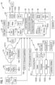
- FIG. 1 represents an electric vehicle (EV) charger upgrading system 105 for upgrading an existing standard EV charger 107 from Grid to Vehicle (V1G) 110(1) operation to Vehicle to Grid (V2G) 110(2) operation in accordance with an exemplary embodiment of the present invention.
- the EV charger upgrading system 105 is capable of upgrading an existing standard AC Electric Vehicle (EV) charger from V1G 110(1) to Vehicle to Grid (V2G) 110(2) in order to send power from a grid 112 to an EV 115 as well as from the EV 115 to the grid 112.
- the EV charger upgrading system 105 is deployed for loading the existing standard EV charger 107 initially developed to support only the V1G 110(1) operation with a V2G compatible firmware 117.
- the EV charger upgrading system 105 is deployed for locally configuring the existing standard EV charger 107 for the Vehicle to Grid (V2G) 110(2) operation to locally enable the existing standard EV charger 107 to allow the V2G 110(2) operation after an inspection 113 such that the existing standard EV charger 107 supports a vehicle to grid (V2G) communication interface 120 for bi-directional charging/discharging of electric vehicles (EVs).
- V2G Vehicle to Grid
- V2G vehicle to grid
- a local configuration 122 requires an authorization 125 via a cloud 127 by a cloud-based service 127(1) for conversion of the existing standard EV charger 107 from V1G 110(1) to V2G 110(2).
- the existing standard EV charger 107 may be a Level 2 AC charger that contains ISO15118 standard capabilities 130 to safely configure it for Vehicle to Grid (V2G) 110(2) operation.
- locally configuring the existing standard EV charger 107 for Vehicle to Grid (V2G) 110(2) operation further comprises loading the existing standard EV charger 107 with an initial setting 132 that only allows V1G functionality.
- the locally configuring the existing standard EV charger 107 for Vehicle to Grid (V2G) 110(2) operation further comprises enabling V2G functionality by performing a configuration of maximum current 135.
- Enabling the V2G 110(2) functionality further comprises providing a user input 137 via a user interface 140 to put the existing standard EV charger 107 in a setup mode 142 by power cycling the existing standard EV charger 107.
- the existing standard EV charger 107 may comprise a controller 145(1) and a memory 145(2) to store the setup mode 142 information.
- the configuration of maximum current 135 information may be stored in the memory 145(2).
- Enabling the V2G 110(2) functionality further comprises, once in the setup mode 142, connecting the existing standard EV charger 107 to a computing device 147 (e.g., a phone, a tablet, a computer) that runs an installation software 150.
- the computing device 147 comprises a processor 152(1), communications 152(3) and a memory 152(2) that stores the installation software 150 and a Bluetooth application (APP) 155.
- the computing device 147 comprises a user interface (U/I) 157 to receive a user input 160.
- the computing device 147 may wirelessly (e.g., Bluetooth, Wi-Fi, and/or cellular) communicate with the existing standard EV charger 107 and the cloud 127.
- Enabling the V2G 110(2) functionality further comprises providing the user input 160 via the user interface 157 for the installation software 150 to login into the cloud 127 where user rights 165 are confirmed. Enabling the V2G 110(2) functionality further comprises, if a user is determined to have technician rights 165(1), allowing the user to change the configuration of the existing standard EV charger 107 from V1G 110(1) to V2G 110(2) via a user input and to configure a maximum allowed reverse current after physically inspecting a location 167 in which the existing standard EV charger 107 is to be installed.
- Enabling the V2G 110(2) functionality further comprises, after the local configuration 122 is performed, allowing a technician to apply a label 170 on the existing standard EV charger 107 for compliance with UL1741 standard, indicating the existing standard EV charger 107 can export energy and at which maximum current.
- the existing standard EV charger 107 further comprises a bi-directional relay 172 to control the flow of current.
- the existing standard EV charger 107 further comprises a DIP switch 175 to limit the current.
- a DIP switch is a manual electric switch that is packaged with others in a group in a standard dual in-line package (DIP).
- the existing standard EV charger 107 further comprises a first DIP switch 175(1) and a second DIP switch 175(2).
- the first DIP switch 175(1) can configure in hardware a maximum current in one direction
- the second DIP switch 175(2) can configure in hardware a maximum current in another direction.
- the existing standard EV charger 107 further comprises a communication interface 177 to communicate with the cloud 127, the computing device 147 and the EV 115.
- the communication interface 177 may support more than one suitable communication protocols such as Bluetooth, Wi-Fi and cellular.
- FIG. 2 it illustrates a method 200 for upgrading the existing standard Electric Vehicle (EV) charger 107 from V1G 110(1) to Vehicle to Grid (V2G) 110(2) operation in accordance with an exemplary embodiment of the present invention.
- EV Electric Vehicle
- V2G Vehicle to Grid
- the method 200 comprises a step 205 of loading the existing standard EV charger 107 initially developed to support only V1G 110(1) with a V2G 110(2) compatible firmware.
- the method 200 further comprises a step 210 of loading the existing standard EV charger 107 with an initial setting that only allows V1G functionality.
- the method 200 further comprises a step 215 of enabling V2G functionality by performing a configuration of maximum current such that a local configuration requires an authorization via a cloud for conversion of the existing standard EV charger 107 from V1G to V2G.
- the existing standard EV charger 107 contains ISO15118 standard capabilities to safely configure it for Vehicle to Grid (V2G) operation.
- FIG. 3 it illustrates a method 300 for upgrading the existing standard Electric Vehicle (EV) charger 107 from V1G 110(1) to Vehicle to Grid (V2G) 110(2) operation in accordance with a first embodiment of the present invention.
- EV Electric Vehicle
- V2G Vehicle to Grid
- the method 300 comprises a step 305 of loading the existing standard EV charger 107 initially developed to support only V1G 110(1) with a V2G 110(2) compatible firmware.
- the method 300 further comprises a step 310 of locally configuring the existing standard EV charger 107 for Vehicle to Grid (V2G) 110(2) operation. Local configuring can be done in a step 315 via setting the DIP switch 175 to limit the current or setting the first and second DIP switches 175(1-2) to set the maximum bidirectional currents.
- FIG. 4 illustrates a method 400 for upgrading the existing standard Electric Vehicle (EV) charger 107 from V1G 110(1) to Vehicle to Grid (V2G) 110(2) operation in accordance with a second embodiment of the present invention.
- EV Electric Vehicle
- V2G Vehicle to Grid
- the method 400 comprises a step 405 of loading the existing standard EV charger 107 initially developed to support only V1G 110(1) with a V2G 110(2) compatible firmware.
- the method 400 further comprises a step 410 of locally configuring the existing standard EV charger 107 for Vehicle to Grid (V2G) 110(2) operation. Local configuring can be done in a step 415 via using the Bluetooth APP 155.
- the Bluetooth APP 155 uses a Bluetooth interface (I/F) 155(1) in which a user input can connect a smartphone such as the computing device 147 to the existing standard EV charger 107 and then the smartphone using an Application Programming Interface (API) 159 (see FIG. 1 ) will configure the existing standard EV charger 107.
- I/F Bluetooth interface
- API Application Programming Interface
- FIG. 5 illustrates a method 500 for upgrading the existing standard Electric Vehicle (EV) charger 107 from V1G 110(1) to Vehicle to Grid (V2G) 110(2) operation in accordance with a third embodiment of the present invention.
- EV Electric Vehicle
- V2G Vehicle to Grid
- the method 500 comprises a step 505 of loading the existing standard EV charger 107 initially developed to support only V1G 110(1) with a V2G 110(2) compatible firmware.
- the method 500 further comprises a step 510 of locally configuring the existing standard EV charger 107 for Vehicle to Grid (V2G) 110(2) operation. Local configuring can be done in a step 515 via using the cloud-based service 127(1) of the cloud 127. In this method, a user would remotely provide the local configuration assuming the right credentialing and control from onsite inspection is available.
- the method for limited maximum "backfeed" of a charging station can be expanded to multiple charging stations that are feeding one single load center or a panel distribution board.
- the total backfeed for the pluarity of charging stations is entered by the contractor via bluetooth or communicated via the cloud environment.
- the system dynamically ensures that the cumulative backfeed from the combination of the charging systems does not exceed the maximum rating as specified by a contractor.
- other chargers such as DC EV chargers may be implemented based on one or more features presented above without deviating from the spirit of the present invention.
- the order of the operations described (1 st load the V2G compatible firmware, 2 nd configure the unit for V1G only, 3 rd inspect the site and configure the unit for V2G) is consistent with the assumption that the selection is done via firmware (Bluetooth local interface, or app using cloud), because the firmware can be loaded with the default of V1G only (so de facto steps 1 and 2 happen at the same time).
- firmware Bluetooth local interface, or app using cloud
- the dip-switch must come pre-set to allow V1G only from the factory, because the firmware update could happen remotely at any time in the future, without the physical presence of the inspector.
- the techniques described herein can be particularly useful for a V1G to a V2G upgrade. While particular embodiments are described in terms of this arrangement, the techniques described herein are not limited to such an arrangement but can also be used with other arrangements such as different EV feature upgrades.
- any examples or illustrations given herein are not to be regarded in any way as restrictions on, limits to, or express definitions of, any term or terms with which they are utilized. Instead, these examples or illustrations are to be regarded as being described with respect to one particular embodiment and as illustrative only. Those of ordinary skill in the art will appreciate that any term or terms with which these examples or illustrations are utilized will encompass other embodiments which may or may not be given therewith or elsewhere in the specification and all such embodiments are intended to be included within the scope of that term or terms.
Landscapes
- Engineering & Computer Science (AREA)
- Power Engineering (AREA)
- Theoretical Computer Science (AREA)
- Mechanical Engineering (AREA)
- Transportation (AREA)
- General Engineering & Computer Science (AREA)
- Software Systems (AREA)
- Computer Security & Cryptography (AREA)
- Physics & Mathematics (AREA)
- General Physics & Mathematics (AREA)
- Computer Hardware Design (AREA)
- Health & Medical Sciences (AREA)
- General Health & Medical Sciences (AREA)
- Bioethics (AREA)
- Computer Networks & Wireless Communication (AREA)
- Signal Processing (AREA)
- Charge And Discharge Circuits For Batteries Or The Like (AREA)
Abstract
Description
- Aspects of the present invention generally relate to a system and a method to upgrade an existing standard Electric Vehicle (EV) charger from Grid to Vehicle (V1G) to Vehicle to Grid (V2G) operation.
- Unlike gas-powered vehicles, electric vehicles (EVs) do not require internal combustion engines to operate. Outfitted with an electric motor and a rechargeable battery pack, EVs move along our roadways without burning up gasoline, or producing harmful exhaust emissions, while generating less noise pollution. The world of transportation continues to rapidly evolve. Sales of electric vehicles (EVs) are expected to expand rapidly in the US in the coming years. Economics aside, there are growing social and political initiatives toward "clean" energy that will push this to become reality. A number of market forecasts indicate electric vehicles will account for nearly 1 in 5 of all vehicles sold within the next 10 years. It is estimated approximately 3 million EVs will be sold in the US in 2028. A rule of thumb by industry analysts is there need be on the order of 20 public EVC stations per EV on the road to support the ecosystem. There were just over 60,000 charging stations in the US at the end of 2019. Thus, tens of thousands will need to be deployed every year for some time as the market grows.
- Charging stations have provided hundreds of millions of charges to EV (electric vehicle) drivers worldwide. When it comes to electric vehicles, the converter is built inside the car. It's called the "onboard charger" though it really is a converter. It converts power from AC to DC and then feeds it into the car's battery. This is the most common charging method for electric vehicles today and most chargers use AC power.
- An EV is connected to AC power, 120V or 240V, and a battery charger in the EV converts the AC power to the DC needed to charge the battery and controls the charging process. In DCFC the DCFC converts the AC power to DC and the DC power is sent directly to the EV battery bypassing the onboard battery charger. There are three categories or types of charging: Trickle Charge, AC Charge and DC Charge. Most drivers of electric vehicles (EVs)-which include all-electric vehicles and plug-in hybrid electric vehicles (PHEVs)-charge their vehicles overnight at home using
AC Level 1 orAC Level 2 charging equipment. - A charging station, also known as a charge point or electric vehicle supply equipment (EVSE), is a piece of equipment that supplies electrical power for charging plug-in electric vehicles (including electric cars, electric trucks, electric buses, neighborhood electric vehicles, and plug-in hybrids). There are two main types: AC charging stations and DC fast chargers. Batteries can only be charged with direct current (DC) electric power, while most electricity is delivered from the power grid as alternating current (AC). For this reason, most electric vehicles have an onboard charger with an AC-to-DC converter (a rectifier). At an AC charging station, power is supplied to the onboard charger.
- In principle, any
AC level 2 EV charger that supports the ISO15118 standard has all the hardware capabilities to send power from the grid to a car, as well as from the car in the grid direction. However, due to the nature in which the neutral connection exists in buildings, these need to be inspected by an electrician before deciding whether what is the maximum safe current level that can be exported towards the grid. There is no way today to upgrade chargers from V1G to V2G, because there is no mechanism to locally enable the charger to allow V2G after an inspection. The existing option is to ship a charger preconfigured to work in V2G mode, and perform configuration of maximum current via a dip-switch during installation. - Therefore, there is a need for a method to configure existing standard AC chargers that contain ISO15118 capabilities to safely configure them for Vehicle to Grid (V2G) operation.
- Briefly described, aspects of the present invention relate to local configuration that requires authorization via the cloud and conversion of an EV charger from V1G to V2G. V1G involves varying the time/rate at which an electric vehicle is charged, while V2G also includes reverse power flow. V1G allows EVs to modify charging rates and time dynamically since it links the EV to the station using a data connection. V1G includes approaches such as charging vehicles in the middle of the day to absorb solar generation that would otherwise need to be shed, or varying the charge rate of electric vehicles to provide frequency response or load balancing services. V2G stands for "vehicle to grid" and is a technology that enables energy to be pushed back to the power grid from the battery of an electric car. Vehicle-to-grid (V2G), also known as Vehicle-to-home (V2H) or Vehicle-to-load (V2L) describes a system in which plug-in electric vehicles (PEV) sell demand response services to the grid. Demand services are either delivering electricity or by reducing their charging rate. Demand services reduce pressure on the grid, which might otherwise experience disruption from load variations. Plug-in electric vehicles include battery electric vehicles (BEV), plug-in hybrids (PHEV), and hydrogen vehicles. They share the ability to generate electricity. That electricity is typically used to power the vehicle. However, at any given time 95% of cars are parked, while their energy sits unused. V2G envisions sending some of the stored power to the grid (or reducing charge rates to pull less power from the grid). The invention describes a method to configure existing standard AC chargers that contain ISO15118 standard capabilities to safely configure them for Vehicle to Grid (V2G) operation. For example, an
AC level 2 EV charger that supports the ISO15118 standard has all the hardware capabilities to send power from the grid to a car, as well as from the car in the grid direction. ISO15118 Road vehicles -- Vehicle to grid communication interface is a proposed international standard defining a vehicle to grid (V2G) communication interface for bi-directional charging/discharging of electric vehicles. The standard provides multiple use cases like secure communication, smart charging and the plug and charge feature used by some electric vehicle networks. - In accordance with one illustrative embodiment of the present invention, a method to upgrade an existing standard AC Electric Vehicle (EV) charger from V1G functionality to Vehicle to Grid (V2G) operation is provided in order to send power from a grid to an EV as well as from the EV to the grid. The method comprises loading the existing standard AC EV charger initially developed to support only V1G with a V2G compatible firmware. The method further comprises locally configuring the existing standard AC EV charger for Vehicle to Grid (V2G) operation to locally enable the existing standard AC EV charger to allow V2G functionality after an inspection such that the existing standard AC EV charger supports a vehicle to grid (V2G) communication interface for bi-directional charging/discharging of electric vehicles (EVs). A local configuration requires an authorization via a cloud for conversion of the existing standard AC EV charger from V1G to V2G.
- In accordance with one illustrative embodiment of the present invention, a method to upgrade an existing standard AC Electric Vehicle (EV)
Level 2 charger from V1G functionality to Vehicle to Grid (V2G) operation in order to send power from a grid to an EV as well as from the EV to the grid. The method comprises loading the existing standard AC EVLevel 2 charger initially developed to support only V1G functionality with a V2G compatible firmware. The method further comprises loading the existing standardAC EV Level 2 charger with an initial setting that only allows V1G functionality. The method further comprises enabling V2G functionality by performing a configuration of maximum current. A local configuration requires an authorization via a cloud for conversion of the existing standardAC EV Level 2 charger from V1G to V2G. The existing standard AC EVLevel 2 charger contains ISO15118 standard capabilities to safely configure it for Vehicle to Grid (V2G) operation. - In accordance with one illustrative embodiment of the present invention, a method to upgrade an existing standard Electric Vehicle (EV) charger from to send power from a grid to an EV as well as from the EV to the grid. The method comprises loading the existing standard EV charger initially developed to support only a grid to an EV charging with the EV to the grid charging compatible firmware. The method further comprises locally configuring the existing standard EV charger for the EV to the grid charging operation to locally enable the existing standard EV charger to allow the EV to the grid charging such that the existing standard EV charger supports an EV to the grid charging communication interface for bi-directional charging/discharging of electric vehicles (EVs). A local configuration requires either an authorization via a cloud or configuring via a computing device having a Bluetooth application (APP) or setting of one or more DIP switches for conversion of the existing standard EV charger from the grid to the EV as well as from the EV to the grid.
- The above described features and advantages, as well as others, will become more readily apparent to those of ordinary skill in the art by reference to the following detailed description and accompanying drawings. While it would be desirable to provide one or more of these or other advantageous features, the teachings disclosed herein extend to those embodiments which fall within the scope of the appended claims, regardless of whether they accomplish one or more of the above-mentioned advantages.
- For a more complete understanding of the present disclosure, and the advantages thereof, reference is now made to the following descriptions taken in conjunction with the accompanying drawings, wherein like numbers designate like objects.
-
FIG. 1 illustrates an electric vehicle (EV) charger upgrading system for upgrading an EV charger from V1G to Vehicle to Grid (V2G) operation in accordance with an exemplary embodiment of the present invention. -
FIG. 2 illustrates a method for upgrading an existing standard Electric Vehicle (EV) charger from V1G to Vehicle to Grid (V2G) operation in accordance with an exemplary embodiment of the present invention. -
FIG. 3 illustrates a method for upgrading an existing standard Electric Vehicle (EV) charger from V1G to Vehicle to Grid (V2G) operation in accordance with a first embodiment of the present invention. -
FIG. 4 illustrates a method for upgrading an existing standard Electric Vehicle (EV) charger from V1G to Vehicle to Grid (V2G) operation in accordance with a second embodiment of the present invention. -
FIG. 5 illustrates a method for upgrading an existing standard Electric Vehicle (EV) charger from V1G to Vehicle to Grid (V2G) operation in accordance with a third embodiment of the present invention. - Various technologies that pertain to systems and methods that facilitate an electric vehicle (EV) charger upgrading that can send power from a grid to an EV as well as from the EV to the grid. The drawings discussed below, and the various embodiments used to describe the principles of the present disclosure in this patent document are by way of illustration only and should not be construed in any way to limit the scope of the disclosure. Those skilled in the art will understand that the principles of the present disclosure may be implemented in any suitably arranged apparatus. It is to be understood that functionality that is described as being carried out by certain system elements may be performed by multiple elements. Similarly, for instance, an element may be configured to perform functionality that is described as being carried out by multiple elements. The numerous innovative teachings of the present application will be described with reference to exemplary non-limiting embodiments.
- To facilitate an understanding of embodiments, principles, and features of the present invention, they are explained hereinafter with reference to implementation in illustrative embodiments. In particular, they are described in the context of an electric vehicle (EV) charger upgrading system and a method that can upgrade an existing standard Electric Vehicle (EV) charger from V1G to Vehicle to Grid (V2G) operation. Embodiments of the present invention, however, are not limited to use in the described devices or methods.
- The components and materials described hereinafter as making up the various embodiments are intended to be illustrative and not restrictive. Many suitable components and materials that would perform the same or a similar function as the materials described herein are intended to be embraced within the scope of embodiments of the present invention.
- These and other embodiments of the electric vehicle (EV) charger upgrading system that can control bi-directional charging according to the present disclosure are described below with reference to
FIGs. 1-5 herein. Like reference numerals used in the drawings identify similar or identical elements throughout the several views. The drawings are not necessarily drawn to scale. - Consistent with one embodiment of the present invention,
FIG. 1 represents an electric vehicle (EV)charger upgrading system 105 for upgrading an existingstandard EV charger 107 from Grid to Vehicle (V1G) 110(1) operation to Vehicle to Grid (V2G) 110(2) operation in accordance with an exemplary embodiment of the present invention. For example, the EVcharger upgrading system 105 is capable of upgrading an existing standard AC Electric Vehicle (EV) charger from V1G 110(1) to Vehicle to Grid (V2G) 110(2) in order to send power from a grid 112 to anEV 115 as well as from theEV 115 to the grid 112. - The EV
charger upgrading system 105 is deployed for loading the existingstandard EV charger 107 initially developed to support only the V1G 110(1) operation with a V2Gcompatible firmware 117. The EVcharger upgrading system 105 is deployed for locally configuring the existingstandard EV charger 107 for the Vehicle to Grid (V2G) 110(2) operation to locally enable the existingstandard EV charger 107 to allow the V2G 110(2) operation after aninspection 113 such that the existingstandard EV charger 107 supports a vehicle to grid (V2G)communication interface 120 for bi-directional charging/discharging of electric vehicles (EVs). In this way, alocal configuration 122 requires anauthorization 125 via acloud 127 by a cloud-based service 127(1) for conversion of the existingstandard EV charger 107 from V1G 110(1) to V2G 110(2). The existingstandard EV charger 107 may be aLevel 2 AC charger that containsISO15118 standard capabilities 130 to safely configure it for Vehicle to Grid (V2G) 110(2) operation. - In operation, locally configuring the existing
standard EV charger 107 for Vehicle to Grid (V2G) 110(2) operation further comprises loading the existingstandard EV charger 107 with aninitial setting 132 that only allows V1G functionality. The locally configuring the existingstandard EV charger 107 for Vehicle to Grid (V2G) 110(2) operation further comprises enabling V2G functionality by performing a configuration of maximum current 135. - Enabling the V2G 110(2) functionality further comprises providing a
user input 137 via auser interface 140 to put the existingstandard EV charger 107 in asetup mode 142 by power cycling the existingstandard EV charger 107. The existingstandard EV charger 107 may comprise a controller 145(1) and a memory 145(2) to store thesetup mode 142 information. The configuration of maximum current 135 information may be stored in the memory 145(2). - Enabling the V2G 110(2) functionality further comprises, once in the
setup mode 142, connecting the existingstandard EV charger 107 to a computing device 147 (e.g., a phone, a tablet, a computer) that runs aninstallation software 150. Thecomputing device 147 comprises a processor 152(1), communications 152(3) and a memory 152(2) that stores theinstallation software 150 and a Bluetooth application (APP) 155. Thecomputing device 147 comprises a user interface (U/I) 157 to receive auser input 160. Thecomputing device 147 may wirelessly (e.g., Bluetooth, Wi-Fi, and/or cellular) communicate with the existingstandard EV charger 107 and thecloud 127. - Enabling the V2G 110(2) functionality further comprises providing the
user input 160 via theuser interface 157 for theinstallation software 150 to login into thecloud 127 whereuser rights 165 are confirmed. Enabling the V2G 110(2) functionality further comprises, if a user is determined to have technician rights 165(1), allowing the user to change the configuration of the existingstandard EV charger 107 from V1G 110(1) to V2G 110(2) via a user input and to configure a maximum allowed reverse current after physically inspecting alocation 167 in which the existingstandard EV charger 107 is to be installed. - Enabling the V2G 110(2) functionality further comprises, after the
local configuration 122 is performed, allowing a technician to apply alabel 170 on the existingstandard EV charger 107 for compliance with UL1741 standard, indicating the existingstandard EV charger 107 can export energy and at which maximum current. - The existing
standard EV charger 107 further comprises abi-directional relay 172 to control the flow of current. The existingstandard EV charger 107 further comprises aDIP switch 175 to limit the current. A DIP switch is a manual electric switch that is packaged with others in a group in a standard dual in-line package (DIP). Alternatively, the existingstandard EV charger 107 further comprises a first DIP switch 175(1) and a second DIP switch 175(2). The first DIP switch 175(1) can configure in hardware a maximum current in one direction and the second DIP switch 175(2) can configure in hardware a maximum current in another direction. The existingstandard EV charger 107 further comprises acommunication interface 177 to communicate with thecloud 127, thecomputing device 147 and theEV 115. Thecommunication interface 177 may support more than one suitable communication protocols such as Bluetooth, Wi-Fi and cellular. - Referring to
FIG. 2 , it illustrates amethod 200 for upgrading the existing standard Electric Vehicle (EV)charger 107 from V1G 110(1) to Vehicle to Grid (V2G) 110(2) operation in accordance with an exemplary embodiment of the present invention. Reference is made to the elements and features described inFIG. 1 . It should be appreciated that some steps are not required to be performed in any particular order, and that some steps are optional. - The
method 200 comprises astep 205 of loading the existingstandard EV charger 107 initially developed to support only V1G 110(1) with a V2G 110(2) compatible firmware. Themethod 200 further comprises astep 210 of loading the existingstandard EV charger 107 with an initial setting that only allows V1G functionality. Themethod 200 further comprises astep 215 of enabling V2G functionality by performing a configuration of maximum current such that a local configuration requires an authorization via a cloud for conversion of the existingstandard EV charger 107 from V1G to V2G. The existingstandard EV charger 107 contains ISO15118 standard capabilities to safely configure it for Vehicle to Grid (V2G) operation. - Turning now to
FIG. 3 , it illustrates amethod 300 for upgrading the existing standard Electric Vehicle (EV)charger 107 from V1G 110(1) to Vehicle to Grid (V2G) 110(2) operation in accordance with a first embodiment of the present invention. Reference is made to the elements and features described inFIG. 1 . It should be appreciated that some steps are not required to be performed in any particular order, and that some steps are optional. - The
method 300 comprises astep 305 of loading the existingstandard EV charger 107 initially developed to support only V1G 110(1) with a V2G 110(2) compatible firmware. Themethod 300 further comprises astep 310 of locally configuring the existingstandard EV charger 107 for Vehicle to Grid (V2G) 110(2) operation. Local configuring can be done in astep 315 via setting theDIP switch 175 to limit the current or setting the first and second DIP switches 175(1-2) to set the maximum bidirectional currents. -
FIG. 4 illustrates amethod 400 for upgrading the existing standard Electric Vehicle (EV)charger 107 from V1G 110(1) to Vehicle to Grid (V2G) 110(2) operation in accordance with a second embodiment of the present invention. Reference is made to the elements and features described inFIG. 1 . It should be appreciated that some steps are not required to be performed in any particular order, and that some steps are optional. - The
method 400 comprises astep 405 of loading the existingstandard EV charger 107 initially developed to support only V1G 110(1) with a V2G 110(2) compatible firmware. Themethod 400 further comprises astep 410 of locally configuring the existingstandard EV charger 107 for Vehicle to Grid (V2G) 110(2) operation. Local configuring can be done in astep 415 via using theBluetooth APP 155. TheBluetooth APP 155 uses a Bluetooth interface (I/F) 155(1) in which a user input can connect a smartphone such as thecomputing device 147 to the existingstandard EV charger 107 and then the smartphone using an Application Programming Interface (API) 159 (seeFIG. 1 ) will configure the existingstandard EV charger 107. - As seen in
FIG. 5 , illustrates amethod 500 for upgrading the existing standard Electric Vehicle (EV)charger 107 from V1G 110(1) to Vehicle to Grid (V2G) 110(2) operation in accordance with a third embodiment of the present invention. Reference is made to the elements and features described inFIG. 1 . It should be appreciated that some steps are not required to be performed in any particular order, and that some steps are optional. - The
method 500 comprises astep 505 of loading the existingstandard EV charger 107 initially developed to support only V1G 110(1) with a V2G 110(2) compatible firmware. Themethod 500 further comprises astep 510 of locally configuring the existingstandard EV charger 107 for Vehicle to Grid (V2G) 110(2) operation. Local configuring can be done in astep 515 via using the cloud-based service 127(1) of thecloud 127. In this method, a user would remotely provide the local configuration assuming the right credentialing and control from onsite inspection is available. - In an alternative construction, the method for limited maximum "backfeed" of a charging station can be expanded to multiple charging stations that are feeding one single load center or a panel distribution board. In this event, the total backfeed for the pluarity of charging stations is entered by the contractor via bluetooth or communicated via the cloud environment. In this case, the system dynamically ensures that the cumulative backfeed from the combination of the charging systems does not exceed the maximum rating as specified by a contractor.
- While a design of a locally configuring an existing standard
AC EV Level 2 charger is described here a range of one or more other EV chargers are also contemplated by the present invention. For example, other chargers such as DC EV chargers may be implemented based on one or more features presented above without deviating from the spirit of the present invention. - The order of the operations described (1st load the V2G compatible firmware, 2nd configure the unit for V1G only, 3rd inspect the site and configure the unit for V2G) is consistent with the assumption that the selection is done via firmware (Bluetooth local interface, or app using cloud), because the firmware can be loaded with the default of V1G only (so de facto steps 1 and 2 happen at the same time). In the case of the dip-switch implementation, the dip-switch must come pre-set to allow V1G only from the factory, because the firmware update could happen remotely at any time in the future, without the physical presence of the inspector.
- The techniques described herein can be particularly useful for a V1G to a V2G upgrade. While particular embodiments are described in terms of this arrangement, the techniques described herein are not limited to such an arrangement but can also be used with other arrangements such as different EV feature upgrades.
- While embodiments of the present invention have been disclosed in exemplary forms, it will be apparent to those skilled in the art that many modifications, additions, and deletions can be made therein without departing from the spirit and scope of the invention and its equivalents, as set forth in the following claims.
- Embodiments and the various features and advantageous details thereof are explained more fully with reference to the non-limiting embodiments that are illustrated in the accompanying drawings and detailed in the following description. Descriptions of well-known starting materials, processing techniques, components and equipment are omitted so as not to unnecessarily obscure embodiments in detail. It should be understood, however, that the detailed description and the specific examples, while indicating preferred embodiments, are given by way of illustration only and not by way of limitation. Various substitutions, modifications, additions and/or rearrangements within the spirit and/or scope of the underlying inventive concept will become apparent to those skilled in the art from this disclosure.
- As used herein, the terms "comprises," "comprising," "includes," "including," "has," "having" or any other variation thereof, are intended to cover a non-exclusive inclusion. For example, a process, article, or apparatus that comprises a list of elements is not necessarily limited to only those elements but may include other elements not expressly listed or inherent to such process, article, or apparatus.
- Additionally, any examples or illustrations given herein are not to be regarded in any way as restrictions on, limits to, or express definitions of, any term or terms with which they are utilized. Instead, these examples or illustrations are to be regarded as being described with respect to one particular embodiment and as illustrative only. Those of ordinary skill in the art will appreciate that any term or terms with which these examples or illustrations are utilized will encompass other embodiments which may or may not be given therewith or elsewhere in the specification and all such embodiments are intended to be included within the scope of that term or terms.
- In the foregoing specification, the invention has been described with reference to specific embodiments. However, one of ordinary skill in the art appreciates that various modifications and changes can be made without departing from the scope of the invention. Accordingly, the specification and figures are to be regarded in an illustrative rather than a restrictive sense, and all such modifications are intended to be included within the scope of invention.
- Although the invention has been described with respect to specific embodiments thereof, these embodiments are merely illustrative, and not restrictive of the invention. The description herein of illustrated embodiments of the invention is not intended to be exhaustive or to limit the invention to the precise forms disclosed herein (and in particular, the inclusion of any particular embodiment, feature or function is not intended to limit the scope of the invention to such embodiment, feature or function). Rather, the description is intended to describe illustrative embodiments, features and functions in order to provide a person of ordinary skill in the art context to understand the invention without limiting the invention to any particularly described embodiment, feature or function. While specific embodiments of, and examples for, the invention are described herein for illustrative purposes only, various equivalent modifications are possible within the spirit and scope of the invention, as those skilled in the relevant art will recognize and appreciate. As indicated, these modifications may be made to the invention in light of the foregoing description of illustrated embodiments of the invention and are to be included within the spirit and scope of the invention. Thus, while the invention has been described herein with reference to particular embodiments thereof, a latitude of modification, various changes and substitutions are intended in the foregoing disclosures, and it will be appreciated that in some instances some features of embodiments of the invention will be employed without a corresponding use of other features without departing from the scope and spirit of the invention as set forth. Therefore, many modifications may be made to adapt a particular situation or material to the essential scope and spirit of the invention.
- Respective appearances of the phrases "in one embodiment," "in an embodiment," or "in a specific embodiment" or similar terminology in various places throughout this specification are not necessarily referring to the same embodiment. Furthermore, the particular features, structures, or characteristics of any particular embodiment may be combined in any suitable manner with one or more other embodiments. It is to be understood that other variations and modifications of the embodiments described and illustrated herein are possible in light of the teachings herein and are to be considered as part of the spirit and scope of the invention.
- In the description herein, numerous specific details are provided, such as examples of components and/or methods, to provide a thorough understanding of embodiments of the invention. One skilled in the relevant art will recognize, however, that an embodiment may be able to be practiced without one or more of the specific details, or with other apparatus, systems, assemblies, methods, components, materials, parts, and/or the like. In other instances, well-known structures, components, systems, materials, or operations are not specifically shown or described in detail to avoid obscuring aspects of embodiments of the invention. While the invention may be illustrated by using a particular embodiment, this is not and does not limit the invention to any particular embodiment and a person of ordinary skill in the art will recognize that additional embodiments are readily understandable and are a part of this invention.
- It will also be appreciated that one or more of the elements depicted in the drawings/figures can also be implemented in a more separated or integrated manner, or even removed or rendered as inoperable in certain cases, as is useful in accordance with a particular application.
- Benefits, other advantages, and solutions to problems have been described above with regard to specific embodiments. However, the benefits, advantages, solutions to problems, and any component(s) that may cause any benefit, advantage, or solution to occur or become more pronounced are not to be construed as a critical, required, or essential feature or component.
-
- 1. A method to upgrade an existing standard AC Electric Vehicle (EV) charger from Grid to Vehicle (V1G) functionality to Vehicle to Grid (V2G) operation in order to send power from a grid to an EV as well as from the EV to the grid, the method comprising:
- loading the existing standard AC EV charger initially developed to support only V1G with a V2G compatible firmware; and
- locally configuring the existing standard AC EV charger for Vehicle to Grid (V2G) operation to locally enable the existing standard AC EV charger to allow V2G functionality after an inspection such that the existing standard AC EV charger supports a vehicle to grid (V2G) communication interface for bi-directional charging/discharging of electric vehicles (EVs), and
- wherein a local configuration requires an authorization via a cloud for conversion of the existing standard AC EV charger from V1G to V2G.
- 2. The method of
embodiment 1, wherein the existing standard AC EV charger is aLevel 2 charger that contains ISO15118 standard capabilities to safely configure it for Vehicle to Grid (V2G) operation. - 3. The method of
embodiment 1, wherein locally configuring the existing standard AC EV charger for Vehicle to Grid (V2G) operation further comprising:
loading the existing standard AC EV charger with an initial setting that only allows V1G functionality. - 4. The method of
embodiment 3, wherein locally configuring the existing standard AC EV charger for Vehicle to Grid (V2G) operation further comprising:
enabling V2G functionality by performing a configuration of maximum current. - 5. The method of embodiment 4, wherein enabling the V2G functionality further comprising:
providing a user input via a user interface to put the existing standard AC EV charger in a setup mode by power cycling the existing standard AC EV charger. - 6. The method of embodiment 5, wherein enabling the V2G functionality further comprising:
once in the setup mode, connecting the existing standard AC EV charger to a computing device (e.g., a phone, a tablet, a computer) that runs an installation software. - 7. The method of embodiment 6, wherein enabling the V2G functionality further comprising:
providing a user input via the user interface for the installation software to login into the cloud where user rights are confirmed. - 8. The method of embodiment 7, wherein enabling the V2G functionality further comprising:
if a user is determined to have technician rights, allowing the user to change the configuration of the existing standard AC EV charger from V1G to V2G via a user input and to configure a maximum allowed reverse current after physically inspecting a location in which the existing standard AC EV charger is to be installed. - 9. The method of embodiment 8, wherein enabling the V2G functionality further comprising:
after the local configuration is performed, allowing a technician to apply a label on the existing standard AC EV charger for compliance with UL1741 standard, indicating the existing standard AC EV charger can export energy and at which maximum current. - 10. The method of embodiment 9, wherein the existing standard AC EV charger is a
Level 2 charger that contains ISO15118 standard capabilities to safely configure it for Vehicle to Grid (V2G) operation. - 11. A method to upgrade an existing standard AC Electric Vehicle (EV)
Level 2 charger from Grid to Vehicle (V1G) functionality to Vehicle to Grid (V2G) operation in order to send power from a grid to an EV as well as from the EV to the grid, the method comprising:- loading the existing standard
AC EV Level 2 charger initially developed to support only V1G functionality with a V2G compatible firmware; - loading the existing standard
AC EV Level 2 charger with an initial setting that only allows V1G functionality; and - enabling V2G functionality by performing a configuration of maximum current,
- wherein a local configuration requires an authorization via a cloud for conversion of the existing standard
AC EV Level 2 charger from V1G to V2G, and - wherein the existing standard
AC EV Level 2 charger contains ISO15118 standard capabilities to safely configure it for Vehicle to Grid (V2G) operation.
- loading the existing standard
- 12. The method of embodiment 11, wherein enabling the V2G functionality further comprising:
providing a user input via a user interface to put the existing standardAC EV Level 2 charger in a setup mode by power cycling the existing standardAC EV Level 2 charger. - 13. The method of embodiment 12, wherein enabling the V2G functionality further comprising:
once in the setup mode, connecting the existing standardAC EV Level 2 charger to a computing device (e.g., a phone, a tablet, a computer) that runs an installation software. - 14. The method of embodiment 13, wherein enabling the V2G functionality further comprising:
providing a user input via the user interface for the installation software to login into the cloud where user rights are confirmed. - 15. The method of embodiment 14, wherein enabling the V2G functionality further comprising:
- if a user is determined to have technician rights, allowing the user to change the configuration of the existing standard
AC EV Level 2 charger from V1G to V2G via a user input and to configure a maximum allowed reverse current after physically inspecting a location in which the existing standardAC EV Level 2 charger is to be installed; and - after the local configuration is performed, allowing a technician to apply a label on the existing standard
AC EV Level 2 charger for compliance with UL1741 standard, indicating the existing standardAC EV Level 2 charger can export energy and at which maximum current.
- if a user is determined to have technician rights, allowing the user to change the configuration of the existing standard
- 16. A method to upgrade an existing standard Electric Vehicle (EV) charger from to send power from a grid to an EV as well as from the EV to the grid, the method comprising:
- loading the existing standard EV charger initially developed to support only a grid to an EV charging with the EV to the grid charging compatible firmware; and
- locally configuring the existing standard EV charger for the EV to the grid charging operation to locally enable the existing standard EV charger to allow the EV to the grid charging such that the existing standard EV charger supports an EV to the grid charging communication interface for bi-directional charging/discharging of electric vehicles (EVs), and
- wherein a local configuration requires either an authorization via a cloud or configuring via a computing device having a Bluetooth application (APP) or setting of one or more DIP switches for conversion of the existing standard EV charger from the grid to the EV as well as from the EV to the grid.
- 17. The method of embodiment 16, wherein the existing standard EV charger is a
AC Level 2 charger that contains ISO15118 standard capabilities to safely configure it for Vehicle to Grid (V2G) operation. - 18. The method of embodiment 16, wherein locally configuring the existing standard EV charger further comprising:
- loading the existing standard EV charger with an initial setting that only allows the grid to the EV functionality.
- 19. The method of embodiment 18, wherein locally configuring the existing standard EV charger further comprising:
- enabling Vehicle to Grid (V2G) functionality by performing a configuration of maximum current.
- 20. The method of embodiment 19, wherein enabling the V2G functionality further comprising:
- providing a user input via a user interface to put the existing standard EV charger in a setup mode by power cycling the existing standard EV charger;
- once in the setup mode, connecting the existing standard EV charger to a computing device (e.g., a phone, a tablet, a computer) that runs an installation software;
- providing a user input via the user interface for the installation software to login into the cloud where user rights are confirmed;
- if a user is determined to have technician rights, allowing the user to change the configuration of the existing standard EV charger from V1G to V2G via a user input and to configure a maximum allowed reverse current after physically inspecting a location in which the existing standard EV charger is to be installed; and
- after the local configuration is performed, allowing a technician to apply a label on the existing standard EV charger for compliance with UL1741 standard, indicating the existing standard EV charger can export energy and at which maximum current.
Claims (15)
- A method to upgrade an existing standard AC Electric Vehicle (EV) charger from Grid to Vehicle (V1G) functionality to Vehicle to Grid (V2G) operation in order to send power from a grid to an EV as well as from the EV to the grid, the method comprising:loading the existing standard AC EV charger initially developed to support only V1G with a V2G compatible firmware; andlocally configuring the existing standard AC EV charger for Vehicle to Grid (V2G) operation to locally enable the existing standard AC EV charger to allow V2G functionality after an inspection such that the existing standard AC EV charger supports a vehicle to grid (V2G) communication interface for bi-directional charging/discharging of electric vehicles (EVs), andwherein a local configuration requires an authorization via a cloud for conversion of the existing standard AC EV charger from V1G to V2G.
- The method of claim 1, wherein the existing standard AC EV charger is a Level 2 charger that contains ISO15118 standard capabilities to safely configure it for Vehicle to Grid (V2G) operation.
- The method of claim 1 or 2, wherein locally configuring the existing standard AC EV charger for Vehicle to Grid (V2G) operation further comprising:
loading the existing standard AC EV charger with an initial setting that only allows V1G functionality. - The method of and of the claims 1 to 3, wherein locally configuring the existing standard AC EV charger for Vehicle to Grid (V2G) operation further comprising:
enabling V2G functionality by performing a configuration of maximum current. - The method of claim 4, wherein enabling the V2G functionality further comprising:
providing a user input via a user interface to put the existing standard AC EV charger in a setup mode by power cycling the existing standard AC EV charger. - The method of claim 4 or 5, wherein enabling the V2G functionality further comprising:
once in the setup mode, connecting the existing standard AC EV charger to a computing device (e.g., a phone, a tablet, a computer) that runs an installation software. - The method according to any of the claims 4 to 6, wherein enabling the V2G functionality further comprising:
providing a user input via the user interface for the installation software to login into the cloud where user rights are confirmed. - The method according to any of the claims 4 to 7, wherein enabling the V2G functionality further comprising:
if a user is determined to have technician rights, allowing the user to change the configuration of the existing standard AC EV charger from V1G to V2G via a user input and to configure a maximum allowed reverse current after physically inspecting a location in which the existing standard AC EV charger is to be installed. - The method according to any of the claims 4 to 8, wherein enabling the V2G functionality further comprising:
after the local configuration is performed, allowing a technician to apply a label on the existing standard AC EV charger for compliance with UL1741 standard, indicating the existing standard AC EV charger can export energy and at which maximum current. - The method of claim 9, wherein the existing standard AC EV charger is a Level 2 charger that contains ISO15118 standard capabilities to safely configure it for Vehicle to Grid (V2G) operation.
- A method to upgrade an existing standard AC Electric Vehicle (EV) Level 2 charger from Grid to Vehicle (V1G) functionality to Vehicle to Grid (V2G) operation in order to send power from a grid to an EV as well as from the EV to the grid, the method comprising:loading the existing standard AC EV Level 2 charger initially developed to support only V1G functionality with a V2G compatible firmware;loading the existing standard AC EV Level 2 charger with an initial setting that only allows V1G functionality; andenabling V2G functionality by performing a configuration of maximum current,wherein a local configuration requires an authorization via a cloud for conversion of the existing standard AC EV Level 2 charger from V1G to V2G, andwherein the existing standard AC EV Level 2 charger contains ISO15118 standard capabilities to safely configure it for Vehicle to Grid (V2G) operation.
- The method of claim 11,
wherein enabling the V2G functionality further comprising:providing a user input via a user interface to put the existing standard AC EV Level 2 charger in a setup mode by power cycling the existing standard AC EV Level 2 charger; and/oronce in the setup mode, connecting the existing standard AC EV Level 2 charger to a computing device (e.g., a phone, a tablet, a computer) that runs an installation software, wherein enabling the V2G functionality further comprising: providing a user input via the user interface for the installation software to login into the cloud where user rights are confirmed; and/orif a user is determined to have technician rights, allowing the user to change the configuration of the existing standard AC EV Level 2 charger from V1G to V2G via a user input and to configure a maximum allowed reverse current after physically inspecting a location in which the existing standard AC EV Level 2 charger is to be installed; andafter the local configuration is performed, allowing a technician to apply a label on the existing standard AC EV Level 2 charger for compliance with UL1741 standard, indicating the existing standard AC EV Level 2 charger can export energy and at which maximum current. - A method to upgrade an existing standard Electric Vehicle (EV) charger from to send power from a grid to an EV as well as from the EV to the grid, the method comprising:loading the existing standard EV charger initially developed to support only a grid to an EV charging with the EV to the grid charging compatible firmware; andlocally configuring the existing standard EV charger for the EV to the grid charging operation to locally enable the existing standard EV charger to allow the EV to the grid charging such that the existing standard EV charger supports an EV to the grid charging communication interface for bi-directional charging/discharging of electric vehicles (EVs), andwherein a local configuration requires either an authorization via a cloud or configuring via a computing device having a Bluetooth application (APP) or setting of one or more DIP switches for conversion of the existing standard EV charger from the grid to the EV as well as from the EV to the grid.
- The method of claim 13,wherein the existing standard EV charger is a AC Level 2 charger that contains ISO15118 standard capabilities to safely configure it for Vehicle to Grid (V2G) operation; and/orwherein locally configuring the existing standard EV charger further comprising: loading the existing standard EV charger with an initial setting that only allows the grid to the EV functionality, wherein locally configuring the existing standard EV charger further comprising: enabling Vehicle to Grid (V2G) functionality by performing a configuration of maximum current.
- The method of claim 14, wherein enabling the V2G functionality further comprising:providing a user input via a user interface to put the existing standard EV charger in a setup mode by power cycling the existing standard EV charger;once in the setup mode, connecting the existing standard EV charger to a computing device (e.g., a phone, a tablet, a computer) that runs an installation software;providing a user input via the user interface for the installation software to login into the cloud where user rights are confirmed;if a user is determined to have technician rights, allowing the user to change the configuration of the existing standard EV charger from V1G to V2G via a user input and to configure a maximum allowed reverse current after physically inspecting a location in which the existing standard EV charger is to be installed; andafter the local configuration is performed, allowing a technician to apply a label on the existing standard EV charger for compliance with UL1741 standard, indicating the existing standard EV charger can export energy and at which maximum current.
Applications Claiming Priority (1)
| Application Number | Priority Date | Filing Date | Title |
|---|---|---|---|
| US18/068,963 US20240201974A1 (en) | 2022-12-20 | 2022-12-20 | Upgrading an existing standard electric vehicle (ev) charger from grid to vehicle (v1g) to v1g plus vehicle to grid (v2g) operation |
Publications (1)
| Publication Number | Publication Date |
|---|---|
| EP4389510A1 true EP4389510A1 (en) | 2024-06-26 |
Family
ID=89223957
Family Applications (1)
| Application Number | Title | Priority Date | Filing Date |
|---|---|---|---|
| EP23217811.1A Pending EP4389510A1 (en) | 2022-12-20 | 2023-12-19 | Upgrading an existing standard electric vehicle (ev) charger from grid to vehicle (v1g) to v1g plus vehicle to grid (v2g) operation |
Country Status (2)
| Country | Link |
|---|---|
| US (1) | US20240201974A1 (en) |
| EP (1) | EP4389510A1 (en) |
Families Citing this family (1)
| Publication number | Priority date | Publication date | Assignee | Title |
|---|---|---|---|---|
| US12609980B2 (en) * | 2024-02-05 | 2026-04-21 | Toyota Motor North America, Inc. | Content delivery based on a vehicle providing energy |
Citations (1)
| Publication number | Priority date | Publication date | Assignee | Title |
|---|---|---|---|---|
| KR20210001181A (en) * | 2019-06-27 | 2021-01-06 | 르노삼성자동차 주식회사 | V2X bidirectional charging/discharging module and method for building bi-directional charging infrastructure for electric vehicle using the same |
Family Cites Families (2)
| Publication number | Priority date | Publication date | Assignee | Title |
|---|---|---|---|---|
| US11173804B2 (en) * | 2019-10-01 | 2021-11-16 | Honda Motor Co., Ltd. | V1G or V2G selection |
| US11673483B2 (en) * | 2020-01-13 | 2023-06-13 | NAD Grid Corp | Methods and systems for facilitating charging sessions for electric vehicles |
-
2022
- 2022-12-20 US US18/068,963 patent/US20240201974A1/en active Pending
-
2023
- 2023-12-19 EP EP23217811.1A patent/EP4389510A1/en active Pending
Patent Citations (1)
| Publication number | Priority date | Publication date | Assignee | Title |
|---|---|---|---|---|
| KR20210001181A (en) * | 2019-06-27 | 2021-01-06 | 르노삼성자동차 주식회사 | V2X bidirectional charging/discharging module and method for building bi-directional charging infrastructure for electric vehicle using the same |
Non-Patent Citations (1)
| Title |
|---|
| "Road vehicles - Vehicle to grid communication interface - Part 1: General information and use case definition", 2 April 2019 (2019-04-02), pages 1 - 117, XP082044161, Retrieved from the Internet <URL:https://api.iec.ch/harmonized/publications/download/309955> [retrieved on 20190402] * |
Also Published As
| Publication number | Publication date |
|---|---|
| US20240201974A1 (en) | 2024-06-20 |
Similar Documents
| Publication | Publication Date | Title |
|---|---|---|
| EP3459786A1 (en) | Electrically powered vehicle and control method for electrically powered vehicle | |
| US9493082B1 (en) | Battery charging station | |
| US20230131483A1 (en) | Charging system for electric vehicles | |
| JP7420061B2 (en) | Server, power management method | |
| US11400825B2 (en) | AC/DC EVSE charging system | |
| US10101397B2 (en) | Electric vehicle charge-related information processing and display | |
| CN109484221A (en) | Electric car and the external charging method of electric car | |
| US12558989B2 (en) | Integrated multi-port electric vehicle (EV) charging system | |
| JP2014045536A (en) | Charging system | |
| EP4389510A1 (en) | Upgrading an existing standard electric vehicle (ev) charger from grid to vehicle (v1g) to v1g plus vehicle to grid (v2g) operation | |
| JP6031953B2 (en) | Charging system | |
| EP4262046B1 (en) | Vehicle and communication control method for the same | |
| JP2023551333A (en) | Electrical energy scheduling method, vehicle controller, battery management system, system, device and medium | |
| KR20190081224A (en) | Charging apparatus for electric vehicle and method for controlling thereof | |
| JP5573125B2 (en) | Charging stand and vehicle charging method | |
| EP4484211A1 (en) | Modular and field upgradable infrastructure device such as electric vehicle supply equipment (evse) for electric vehicle (ev) charging | |
| CN107148713A (en) | Charging device | |
| US20230264592A1 (en) | Charging of Electric Vehicles | |
| EP4397532A1 (en) | Configuring offline electric vehicle supply equipment (evse) via 2-factor authentication | |
| US20250018823A1 (en) | On-site device to diagnose and recover offline networked electric vehicle supply equipments (evses) | |
| EP4418189A1 (en) | Acquiring time for an electric vehicle supply equipment (evse) based on a short-range wireless communication-based automated process | |
| JP2018033314A (en) | Electric car and charger | |
| CN120003275A (en) | vehicle | |
| JP2022068401A (en) | On-vehicle charger, on-vehicle charge system, and charge control method | |
| KR20140016651A (en) | Method for charging of vehicle |
Legal Events
| Date | Code | Title | Description |
|---|---|---|---|
| PUAI | Public reference made under article 153(3) epc to a published international application that has entered the european phase |
Free format text: ORIGINAL CODE: 0009012 |
|
| STAA | Information on the status of an ep patent application or granted ep patent |
Free format text: STATUS: THE APPLICATION HAS BEEN PUBLISHED |
|
| AK | Designated contracting states |
Kind code of ref document: A1 Designated state(s): AL AT BE BG CH CY CZ DE DK EE ES FI FR GB GR HR HU IE IS IT LI LT LU LV MC ME MK MT NL NO PL PT RO RS SE SI SK SM TR |
|
| STAA | Information on the status of an ep patent application or granted ep patent |
Free format text: STATUS: REQUEST FOR EXAMINATION WAS MADE |
|
| 17P | Request for examination filed |
Effective date: 20241128 |
|
| RBV | Designated contracting states (corrected) |
Designated state(s): AL AT BE BG CH CY CZ DE DK EE ES FI FR GB GR HR HU IE IS IT LI LT LU LV MC ME MK MT NL NO PL PT RO RS SE SI SK SM TR |