EP4389448A1 - Personalization module for security documents - Google Patents
Personalization module for security documents Download PDFInfo
- Publication number
- EP4389448A1 EP4389448A1 EP22215166.4A EP22215166A EP4389448A1 EP 4389448 A1 EP4389448 A1 EP 4389448A1 EP 22215166 A EP22215166 A EP 22215166A EP 4389448 A1 EP4389448 A1 EP 4389448A1
- Authority
- EP
- European Patent Office
- Prior art keywords
- prism
- module
- document
- marking
- personalization
- Prior art date
- Legal status (The legal status is an assumption and is not a legal conclusion. Google has not performed a legal analysis and makes no representation as to the accuracy of the status listed.)
- Granted
Links
Images


Classifications
-
- B—PERFORMING OPERATIONS; TRANSPORTING
- B42—BOOKBINDING; ALBUMS; FILES; SPECIAL PRINTED MATTER
- B42D—BOOKS; BOOK COVERS; LOOSE LEAVES; PRINTED MATTER CHARACTERISED BY IDENTIFICATION OR SECURITY FEATURES; PRINTED MATTER OF SPECIAL FORMAT OR STYLE NOT OTHERWISE PROVIDED FOR; DEVICES FOR USE THEREWITH AND NOT OTHERWISE PROVIDED FOR; MOVABLE-STRIP WRITING OR READING APPARATUS
- B42D25/00—Information-bearing cards or sheet-like structures characterised by identification or security features; Manufacture thereof
- B42D25/40—Manufacture
- B42D25/405—Marking
- B42D25/41—Marking using electromagnetic radiation
Definitions
- the present invention relates to personalization modules, for personalization of security documents/booklets, where in particular documents/booklets are identity documents.
- Identity document shall be interpreted as a document containing information relating to its holder, that can be issued by an authority / government such as for instance a passport or an identity card etc., or a non-official document that can be issued by private firms, such as for instance season tickets, subscription cards, etc.
- Documents are flat and comprise a multiple laser image (MLI) or a changeable laser image (CLI), which are secure elements especially in the market of governmental documents, but not limited to.
- MLI multiple laser image
- CLI changeable laser image
- MLI or CLI is called flip image, or without distinction tilt image.
- MLI or CLI are visible of with a lenticular array, having a main direction of orientation.
- MLI are visible when flipping, tilting or rotating the document around an « horizontal » direction of orientation parallel to the reading direction; where CLI are visible around a « vertical » direction of orientation.
- MLI or CLI are typically used for personalization purpose of the document. They are produced and visible through an array of fine cylindrical lenticular lenses, also called lenticular screen, with a radius as little as a few microns, which are disposed on a flat support, and which enable an easy-to-check visible security feature where two pieces of information can be seen depending on the viewing angle.
- the cylindrical lenticular lenses of MLI or CLI are orientated along a main direction of orientation.
- the main direction of orientation of the lenticular lenses for the MLI is perpendicular to the main direction of orientation of the lenticular lenses for the CLI.
- a flip image is written on a document with help of a lenticular screen and can be seen with help of said lenticular screen on said flat support.
- a flip image in fact shows two different contents or two different images, each content or image seen depending on the viewing angle.
- a flip image can be a set of two image elements such as e.g. a portrait, a logo, a symbol, a number, a chain of characters, etc.
- a flip image relates to the holder of the document. Accordingly, a flip image is used for personalization and securitization of the document.
- each MLI or CLI is a laser-marked, laser-engraved, with a flipping set of two image elements, which become unalterable after marking, making it almost impossible to forge the document at a later stage.
- the present invention relates precisely to a device for writing a flip image on a document.
- EP2050574 relates to a device for writing a tilt image structure on a base body, comprising a set of deflection mirrors.
- EP2050574 it is required to arrange a set of two or event four deflection mirrors, which is complex and cumbersome.
- the present invention aims to provide a solution which is simpler, more flexible and smaller in size.
- the present invention relates to a personalization module (100), for personalization of a security document (200), said document (200) comprising a marking area for marking a two-image element MLI or CLI through an array (210) of lenticular lenses having a main direction of elongation, said personalization module (100) comprising:
- It may further comprise a set of at least one transport mechanism, said set being configured to implement at least one of the following movements:
- the set of at least one transport mechanism is further configured to move the prism (300) at least in a vertical direction.
- the set of at least one transport mechanism is configured to move the prism (300) form a resting position (RP) to a working position (MP), where when viewed from above, the prism (300) is away from the marking zone in the resting position (RP) and over the marking zone in the working position (MP).
- the set of at least one transport mechanism comprises rotating means to rotate the position of the prism (300) in a horizontal plane.
- the prism (300) comprises at least two faces where the laser beam (520) is incident, said faces being coated with anti-reflective coating.
- the prism (300) is isosceles and has a rectangular shaped base which is configured to be parallel to the document (200).
- the prism (300) presents an axis of symmetry which is elongated along a direction which is parallel to the lenticular array (210) main direction of elongation.
- it further comprises a shutter (120).
- the shutter (120) is movable over the document (200) in a plane which is parallel to said document (200), the movement of the shutter possibly being a translation, a rotation or a combination of both a translation and a rotation.
- it further comprises:
- it further comprises a vision system, comprising a camera, aimed at ensuring at least one of the following:
- it further comprises a chip encoding module, configured to read and to encode a chip comprised within the document (200).
- the prism (300) presents one of the following shapes:
- the personalization module according to the present invention will be referred to as "personalization module".
- the insertion of a document 200 in the personalization module or in a device comprising the personalization module according to the present invention can be automatic or manual.
- It relates to a module for personalization of documents, used in any device or machine, and in particular relates to a stand-alone personalization module or device, including a desktop device where dimension optimisation is of particular interest.
- the personalization module 100 may further comprise a casing 110, or be incorporated in an existing casing 430, for instance as illustrated on figure 2 , wherein the prism is not visible.
- the personalization module 100 will be described as if based on a horizontal support, such as e.g. a table or a desktop.
- the document personalization module 100 is configured to be able to operate paper documents and hybrid documents which comprise both paper and polycarbonate pages, such as passports, as well as full polycarbonate documents such as identity cards, driving licenses, etc. within the same module or device.
- the personalization module 100 can be integrated as a modular element in a device comprising further personalization elements or modules, securing long-term personalization solution investment, particularly for secure passport issuance offices and centers.
- the personalization module 100 comprises a longitudinal axis, here called Y-axis, along which documents are moved as described later.
- Figure 2 illustrates another embodiment of a casing 430 preferably comprising at least one air vent (not illustrated), to vent a laser marking module 500 described here after.
- the casing 430 also advantageously comprises a fan (not illustrated).
- the casing 430 may further comprise a set of legs having an adjustable height, to compensate for any lack of horizontality.
- All personalization elements of a document 200 which are laser marked are on the same polycarbonate (PC) page.
- ID cards are usually personalized on both sides as both sides are made of PC.
- the personalization module 100 can be integrated in a personalization device such as e.g. illustrated in figure 2 .
- a personalization device such as e.g. illustrated in figure 2 .
- the prism 300 is not illustrated. It is located inside the inkjet printing module 400, underneath the laser marking module 500.
- the personalization device of figure 2 is preferably a front operated system with manual document 200 insertion and retrieval, or an automated system, thanks to a very precise moving tray of a transport mechanism, aimed at handling the document 200 within the device according to the invention, to ensure high-precision movement for high-quality personalization.
- the personalization module 100 comprises a laser marking module 500 comprising a laser marking head 530.
- the prism 300 In operation, on the working position MP, the prism 300 is located above the page of document 200 to be personalized.
- the laser marking module 500 can be located above the document 200 to be personalized, as illustrated in figure 2 , or distant from the page of document 200 to be personalized, as illustrated on figure 7 .
- the laser marking head 530 is configured to mark predetermined areas of a polycarbonate page (and/or certain types of paper) of a passport within a marking zone - or indistinctively area - where, by "marking", it is understood any of the following processes: marking, engraving, color change / blackening / bleaching, carbonization, ablation.
- the size of the marking zone is inferior or equal to the size of the page of a passport, especially a polycarbonate page.
- Predetermined marking areas correspond typically to predetermined identification zones of the document body such as, for instance, the MRZ, portrait of its holder, his or her name, date of birth, a MLI or a CLI etc.
- the laser head 530 is stationary.
- the laser head 530 is adjacent to the printing bridge of the optional inkjet printing module 400 described later, such that the marking zone and the printing zone are at least partly combined.
- the laser head 530 can be located above the inkjet printing module 400, as illustrated in figure 2 .
- the laser beam 520 from the laser head 530 of the laser marking module 500 can go through an opening 131 made in a horizontal rigid plate 130 of the casing 430 between the laser marking module 500 and the inkjet printing module 400.
- the laser marking module 500 which comprises the laser head 530, can mark any of the predetermined areas thanks to a laser scanner, which comprises a set of at least one tiltable mirror 540 and associated driver(s), e.g. piezoelectric driver(s). For this reason, the laser module is indistinctively considered as the laser scanner.
- MRZ position is defined by ICAO standards.
- personalization data can be located anywhere on a document 200.
- the laser beam 520 can be directed anywhere on the document 200; it is positioned thanks to the mirrors of the laser scanner to mark directly personalization data in corresponding predetermined area(s), meaning with no optical means between the mirrors of the laser scanner and the document 200.
- a prism 300 described later is required/needed.
- the laser head 530 is configured to perform all types of marking while the tray is positioned under the laser marking module 500 such as:
- the prism 300 may adopt:
- One of the at least three following different laser sources can be implemented:
- the laser head 530 emits a laser horizontal beam, parallel to the plane of the document 200.
- the laser beam 520 from the laser head 530 is directed to tiltable scanning mirrors 540 of the laser scanner, the movement of which allowing to cover the area of the document 200, as illustrated on figure 3 .
- scanning mirrors 540 adopt a first position (in plain lines) to mark the first image element of a CLI/MLI; and a second position (in dashed lines) to mark the second image element of a CLI/MLI, such that the laser beam 520 can be diverted to one side or the other of the prism 300.
- scanning mirrors 540 are located on the axis of symmetry OS of the prism 300.
- scanning mirrors 540 are shifted from the axis of symmetry OS of the prism 300.
- Scanning mirrors 540 are located above the array 210 of cylindrical lenticular lenses, in line with the MLI/CLI to be engraved, as illustrated on figure 4 .
- scanning mirrors 540 are plane mirrors. Typically, they can be part of a on-the-shelf laser scanner. They can be tilted at least around a horizontal axis, which is preferably located in line with the middle of the array 210 of cylindrical lenticular lenses.
- the laser marking module 500 may be a stand-alone module comprising a casing 110, which can be fixed e.g. with screws to another casing 430, allowing the laser marking module 500 to be secured within the casing 110 but being nonetheless removable in times of need. Accordingly, the laser marking module 500 is interchangeable with another laser marking module 500, for example if there is a need for a more powerful laser.
- the laser marking module 500 advantageously comprises a communication module, configured to enable a communication between the laser marking module 500 and a remote computer comprising a display screen.
- the communication module comprises a USB communication port.
- neither the laser marking module 500 nor the laser marking head can be moved in translation along the Y-axis or the X-axis, which is perpendicular to the Y-axis in a horizontal plane.
- the laser marking module 500 may comprise an air vent 510, the position of which preferably corresponding to the position of the air vent of the casing 430.
- a MLI/CLI comprises 2 image elements: a first image element in contact with a second image element.
- the first image element of a MLI/CLI is marked with the laser beam 540 having a first angle of incidence on a given cylindrical lenticule and the second image element of the MLI/CLI is marked with the laser beam 540 having a second angle of incidence on said cylindrical lenticule, as illustrated on figure 3 or figure 9 .
- the laser scanner alone is not sufficient, it is necessary to modify the optical path of the laser beam 520.
- the present invention advantageously implements here refractive means, in this case an optical prism, here after “prism”, which is described here after.
- the personalization module 100 comprises an optical prism 300, here after "prism”.
- the prism 300 is isosceles and has a rectangular shaped base which is configured to be parallel to the document 200, which is parallel to the lenticular array 210, as illustrated on figure 1 .
- the prism 300 is a triangular prism 300.
- the prism 300 is a right isosceles triangular prism 300, presenting an angle of 90° at the top, also called the apex, of the prism 300.
- the prism 300 is a truncated triangular prism.
- the prism 300 is a 4 faces pyramidal shaped prism 300.
- the prism 300 is a truncated 4 faces pyramidal shaped prism 300, presenting a rectangular shaped base 320 which is parallel to the document 200.
- the top of the prism 300 is preferably flat, and preferably parallel to its base.
- the top of the prism 300 can be used as a surface of contact with a transport means.
- the rectangular shaped base presents a surface which is greater than or equal to the surface of the array 210 of cylindrical lenticular lenses.
- the width of the prism 300 is wider than the width of the lenticular array 210.
- the prism 300 has an edge 310 which is preferably located in line with the middle of the lenticular array 210.
- the edge 310 of the prism 300 is elongated along a direction which is parallel to the lenticular array 210 main direction of elongation.
- the vertical distance between the edge 310 of the prism 300 and the laser head 530 is less than a predefined threshold.
- the distance between the tiltable scanning mirrors 540 of the laser scanner and the prism can be small, e.g. between 10 cm and 20 cm, the personalization module 100 can be particularly compact in size.
- the vertical distance between the lenticular array 210 and the rectangular shaped base 320, or bottom, of the prism 300 is less than a predefined threshold, in this case less than 20 mm.
- the prism 300 is movable.
- the prism 300 is placed in a resting position RP, away from the MLI zone or the CLI zone, and away from the document 200, in order to protect it from inkjet droplets or any other polluting source.
- the prism 300 is then moved to a working position MP, or marking position, over the MLI zone or the CLI zone.
- the prism 300 is movable over the document 200 in a plane which is parallel to said document 200, alongside at least one of the X-axis and the Y-axis. Accordingly, the position of the prism 300 is adaptable to various sorts of document 200 (for instance a standard passport and a civil passport, etc.), wherever the MLI/CLI is located.
- the document 200 may be moved relatively to the prism 300 in a horizontal plane, for instance for even more precise marking of the first image element and the second image element of the CLI/MLI.
- the prism 300 is movable over the document 200 in a vertical direction.
- Movements of the prism 300 in a horizontal direction, in a horizontal plane or in the vertical direction can be implemented with help of a respective micro stepper motor, leading to a fine tuning of the position of the prism 300, as low as a tenth of a millimeter.
- the prism 300 can be rotated, in this case over a horizontal direction parallel to the X-axis.
- the prism 300 can also be rotated with a vertical axis of rotation, as illustrated on figure 5 .
- Such rotation can be useful to change from a MLI marking to a CLI marking and also to put the prism in a safe area /rest position when not in use.
- a same personalization module 100 can be implemented for a first type of document 200 comprising a CLI and a second type of document 200 comprising a MLI, for instance a passport and ID card.
- Rotating the prism 300 allows the same prism 300 to be used for both CLI and MLI (generally lenticules main direction for CLI is perpendicular to lenticular grating main direction for MLI).
- the personalization module 100 comprises two prisms 300, a first prism 300 configured to engrave a MLI, and a second prism 300 configured to engrave a CLI.
- At least the two faces of the prism 300 adjacent to the base 320 are coated with anti-reflective coating, leading to almost no reflection of the laser beam 520.
- the laser beam 520 is deflected by the mirrors of the laser scanner on one side of the prism 300 or on the opposite side of the prism 300 to mark respectively a first image element and a second image element of the MLI/CLI, as illustrated on figure 1 and figure 3 .
- the present invention allows different tilt image positions in the same personalization module 100, configurable with the layout.
- a same personalization module 100 can mark both CLIs and MLIs of different documents with a same device.
- the present invention relies advantageously on a prism 300, which is a unique, one-piece, element. Accordingly, only one unique optical system is enough to ensure the setting of two engraving directions of the laser beam 520.
- the prism 300 presents a plane base parallel to the plane of the document 200, the prism can be nearer to the document than the mirrors of the prior art, leading to a compact device.
- the laser beam is refracted by the lateral faces of the prism 300.
- it can be incident on the prism at an angle equal to the Brewster angle so that all the light is refracted. Accordingly, there is no reflection, which optimises the energy.
- the prism 300 has the following geometrical dimensions: angle of 90° at its top, angles of 45° between the sides and the base.
- the personalization module 100 can comprise a shutter 120.
- the shutter 120 is movable over the document 200 in a plane which is parallel to said document 200, alongside at least one of the X-axis and the Y-axis.
- Movements of the shutter 120 can be implemented with help of a micro stepper motor, a standard motor or an actuator, as the need for a fine tuning of the position of the shutter 120 is not as strong as the need for a fine tuning of the position of the prism 300.
- the shutter 120 can be rotated, or flipped over a horizontal direction parallel to the X-axis, like a flap.
- the shutter 120 can also be rotated over a vertical direction.
- the movement of the shutter 120 may be combined with the movement of the prism 300.
- the shutter 120 when the prism 300 is in its resting position RP, the shutter 120 is closed and protects the prism 300, especially from dust and form ink droplets when the personalization module 100 further comprises an inkjet printing module 400, described hereafter.
- the personalization module 100 comprises an inkjet printing module 400, which comprises a moveable printing head mounted on a fixed printing bridge. The printing head is movable alongside the X-axis linear direction.
- the printing head can adopt at least the 3 following positions:
- the printing operation is implemented with a plurality of printing positions as a tray supporting the document 200 moves along the Y-axis linear direction during the printing operation.
- the printing head is connected to color and black inkjet cartridges. It is configured to print on any or both of page 2 and page 3 of a document 200. Said colors can be within the visible spectrum, the UV spectrum, the IR spectrum, or any combination thereof. Inkjet cartridges are accessible through an access 410.
- the printing head is configured to print within predetermined printing areas of any paper page, and optionally in addition on a polycarbonate page, of a document 200 within a printing zone.
- the size of the printing zone is inferior or equal to the size of the paper page of a document 200.
- Predetermined printing areas correspond typically to predetermined identification zones of the document 200 holder such as, for instance, the MRZ, his or her portrait, his or her name, date of birth, etc.
- the inkjet printing module 400 comprises a substantially flat horizontal surface on which a transport mechanism, the printing bridge and a flattening mechanism, are mounted.
- the inkjet printing module 400 is based on an existing printer, such as the Hiprint TM P4000, produced by the applicant, which comprises a flattening mechanism; and from which the top of the casing 430 is removed.
- an existing printer such as the Hiprint TM P4000, produced by the applicant, which comprises a flattening mechanism; and from which the top of the casing 430 is removed.
- Hiprint TM P4000 printer can be reused within the proposed personalization module 100, allows transitioning from paper document 200 to polycarbonate document 200 with a smooth investment.
- Such printer offers high quality printing (up to 4800 dpi) for paper booklets personalization. It does include a 4-color inkjet printing head, which can easily be hot swapped by an operator.
- the transport mechanism of the personalization module 100 is the transport mechanism of the inkjet printing module 400, which can be an existing inkjet printer as exposed above. Accordingly, the inkjet printing module 400 comprises the document 200 transport mechanism.
- a transport mechanism is configured to automatically transport a document 200 along a Y-axis linear direction, from an entrance to an exit 140 of the personalization module 100, wherein the entrance and the exit 140 are the same.
- the personalization module 100 is then a front-operated manual feeder, for both document 200 insertion and retrieval.
- a transport mechanism comprises a tray on which the document 200 is placed for marking / printing.
- the tray may be moved along guide bars, which is a high precision mechanism know in itself allowing highly precise positioning of the tray.
- the tray is provided with secure handle, ensuring proper document 200 positioning.
- a transport mechanism comprises a set of at least one clamp to clamp the document 200 open for printing and marking.
- a transport mechanism is configured to transport the document 200 to the printing position and to a marking position, which is different from the printing position.
- a document 200 transport mechanism is configured to transport a document 200 to the printing positions and the marking position with the document 200 having its spine parallel to the X-axis linear direction, typically when the document 200 is a passport.
- Embodiments may be combined.
- the inkjet printing module 400 is accessible through a flap within the casing 430, preferably equipped with a handle 150.
- the opening of the flap e.g. via a handle, enables access to the inkjet printing module 400, e.g. for its repair or replacement.
- the personalization module 100 is modular.
- the size of the flap is bigger than the size of the inkjet printing module 400.
- the opening of the flap shuts off the power to the laser marking head, for instance with a sensor acting as a circuit breaker.
- the flap further comprises a manual hatch (not illustrated), the size of which being bigger than the size of a document 200, to enable manual insertion of a document 200 in the inkjet printing module 400 through that flap.
- the opening of the hatch shuts off the power to the laser marking head. Opening the hatch allows the operator to insert a document 200 without having to open the flap. In such a case, the flap can be open just for maintenance reasons, such as e.g. change of the inkjet cartridges.
- the hatch allows an operator to insert and retrieve a document 200 with just a movement of his hands, which is better in terms of ergonomics than manipulating the flap, which requires an additional movement of the shoulder.
- the inkjet printing module 400 is a stand-alone module fixed within the casing 430, e.g. with screws, allowing the inkjet printing module 400 to be secured within the casing 430 but being nonetheless removable in times of need. Accordingly, the inkjet printing module 400 is interchangeable with another inkjet printing module 400.
- the inkjet printing module 400 comprises a communication module, configured to enable a communication between the inkjet printing module 400 and a remote computer comprising a display screen.
- the inkjet printing module 400 may comprise a display screen 420, e.g. a LCD screen, which is driven by the mother card of the inkjet printing module 400, and which allows to display maintenance information, like e.g. the level of ink left.
- a display screen 420 e.g. a LCD screen
- the personalization module 100 may comprise a vision system, comprising a camera, aimed at ensuring personal data positioning (offset registration).
- the vision system may be used for several purpose:
- the camera is particularly configured to detect the position of the document 200 once positioned on a transport mechanism. It is also configured to drive at least one of the inkjet printing module 400 and the laser marking module 500 according to a comparison of said position with a reference position.
- the camera can detect the position of the document 200, i.e. which of page 2 and page 3 enters first. If the position of the document 200 is improper, a warning message can be triggered, a transport mechanism can be automatically reversed to eject the document 200, or any other suitable operation.
- the personalization module 100 further comprises a detection system, e.g. a presence sensor, typically an optical sensor such as a photocell, or any other detection mechanism to detect the entrance of a document 200 into the personalization module 100 or into a transport mechanism.
- a detection system e.g. a presence sensor, typically an optical sensor such as a photocell, or any other detection mechanism to detect the entrance of a document 200 into the personalization module 100 or into a transport mechanism.
- the camera is close to the laser marking head, where "close” means at a distance inferior to a predetermined value. It is worth noting that several cameras may be provided, e.g. one for the offset registration and one for the document 200 position detection.
- the angle between the optical axis of the camera for the offset registration and the laser beam 520 of the laser marking head is inferior or equal to a predetermined value, here inferior or equal to 10°.
- the vision system comprises a communication module, configured to enable a communication between the camera and a remote computer comprising a display screen.
- the communication module comprises a USB communication port.
- a camera of the vision system is located in the casing 430 above the inkjet printing module 400, adjacent to the laser marking module 500.
- the optical axis of the camera goes through an opening 132 made in the horizontal rigid plate, adjacent to the opening 131, as illustrated on figure 2 .
- the personalization module 100 may comprise a chip encoding module 600 ( figure 7 ), configured to read and to encode a chip comprised within the document 200, especially when the document 200 is a passport.
- the chip is a RFID chip
- the chip encoding module is an RFID encoding module comprising a RFID antenna.
- the RFID module is based on a set including reader electronics and a separate antenna preferably complying with ICAO 9303 requirements.
- the chip encoding module is comprised in the inkjet printing module 400.
- the RFID antenna is located under the tray of the transport mechanism. Thanks to the antenna position, once the booklet is inserted in the personalization module 100, it is possible to establish a communication with the chip, and therefore to start encoding whatever the other operations in progress are. Typically, it is possible to encode while printing and/or marking, which allows significant time saving during the entire personalization process.
- the chip encoding module is integral with the document 200 transport mechanism. Accordingly, the chip of the document 200 can be encoded while the document 200 is being transported from a position to another, both reducing the time of personalization and compacting the personalization module 100. This allows parallel encoding while printing, speeding-up the whole personalization process for more production throughput and efficiency.
- the personalization module 100 is a stand-alone desktop personalization device.
- the chip encoding module 600 comprises a communication module, configured to enable a communication between said chip encoding module and a remote computer comprising a display screen, as illustrated on figure 7 .
- the communication module of the chip encoding module is the same than the communication module of the inkjet printing module 400.
- One only communication module can be provided for the vision system, the laser marking module 500, the inkjet printing module 400 and the chip encoding module.
Landscapes
- Physics & Mathematics (AREA)
- Health & Medical Sciences (AREA)
- Electromagnetism (AREA)
- General Health & Medical Sciences (AREA)
- Toxicology (AREA)
- Engineering & Computer Science (AREA)
- Manufacturing & Machinery (AREA)
- Thermal Transfer Or Thermal Recording In General (AREA)
Abstract
- a laser marking module (500), configured to mark within a marking zone, and comprising a laser head (530) configured to emit a laser beam (520), and a laser scanner equipped with movable mirrors to deflect said laser beam (520) towards said document (200),
- An optical prism (300), configured to refract the laser beam (520) from the laser scanner mirrors to the lenticular lenses, one side of the prism (300) enabling marking a first image element of the MLI or the CLI, the other side of the prism (300) enabling marking a second image element of the MLI or the CLI.
Description
- The present invention relates to personalization modules, for personalization of security documents/booklets, where in particular documents/booklets are identity documents.
- Identity document shall be interpreted as a document containing information relating to its holder, that can be issued by an authority / government such as for instance a passport or an identity card etc., or a non-official document that can be issued by private firms, such as for instance season tickets, subscription cards, etc.
- For the sake of brevity, identity documents, whether in the form of booklets of polycarbonate cards, will be described here after as "documents". Documents are not limited to those comprising polycarbonate but encompass those comprising any engravable materials.
- Documents are flat and comprise a multiple laser image (MLI) or a changeable laser image (CLI), which are secure elements especially in the market of governmental documents, but not limited to.
- MLI or CLI is called flip image, or without distinction tilt image. MLI or CLI are visible of with a lenticular array, having a main direction of orientation. Usually MLI are visible when flipping, tilting or rotating the document around an « horizontal » direction of orientation parallel to the reading direction; where CLI are visible around a « vertical » direction of orientation.
- MLI or CLI are typically used for personalization purpose of the document. They are produced and visible through an array of fine cylindrical lenticular lenses, also called lenticular screen, with a radius as little as a few microns, which are disposed on a flat support, and which enable an easy-to-check visible security feature where two pieces of information can be seen depending on the viewing angle.
- Typically, the cylindrical lenticular lenses of MLI or CLI are orientated along a main direction of orientation. The main direction of orientation of the lenticular lenses for the MLI is perpendicular to the main direction of orientation of the lenticular lenses for the CLI.
- A flip image is written on a document with help of a lenticular screen and can be seen with help of said lenticular screen on said flat support. A flip image in fact shows two different contents or two different images, each content or image seen depending on the viewing angle. A flip image can be a set of two image elements such as e.g. a portrait, a logo, a symbol, a number, a chain of characters, etc.
- Typically for a document according to the present invention, a flip image relates to the holder of the document. Accordingly, a flip image is used for personalization and securitization of the document.
- Today, a document usually comprises either MLI or CLI, but not both.
- During the personalization phase, each MLI or CLI is a laser-marked, laser-engraved, with a flipping set of two image elements, which become unalterable after marking, making it almost impossible to forge the document at a later stage.
- The present invention relates precisely to a device for writing a flip image on a document.
- In this context, it is known document
EP2050574 , which relates to a device for writing a tilt image structure on a base body, comprising a set of deflection mirrors. - According to
EP2050574 , it is required to arrange a set of two or event four deflection mirrors, which is complex and cumbersome. - The present invention aims to provide a solution which is simpler, more flexible and smaller in size.
- According to a first of its objects, the present invention relates to a personalization module (100), for personalization of a security document (200), said document (200) comprising a marking area for marking a two-image element MLI or CLI through an array (210) of lenticular lenses having a main direction of elongation, said personalization module (100) comprising:
- a laser marking module (500), configured to mark within a marking zone, and comprising a laser head (530) configured to emit a laser beam (520), and a laser scanner equipped with movable mirrors to deflect said laser beam (520) towards said document (200).
- It is essentially characterized in that it further comprises:
- An optical prism (300), configured to refract the laser beam (520) from the laser scanner mirrors to the lenticular lenses, one side of the prism (300) enabling marking a first image element of the MLI or the CLI, the other side of the prism (300) enabling marking a second image element of the MLI or the CLI.
- It may further comprise a set of at least one transport mechanism, said set being configured to implement at least one of the following movements:
- transport a security document (200) along a Y-axis linear direction, from an entrance to an exit (140) of the desktop personalization module (100), through a marking position (MP),
- move the prism (300) at least in a horizontal plane, alongside at least one of the X-axis and the Y-axis.
- In one embodiment, the set of at least one transport mechanism is further configured to move the prism (300) at least in a vertical direction.
- In one embodiment, the set of at least one transport mechanism is configured to move the prism (300) form a resting position (RP) to a working position (MP), where when viewed from above, the prism (300) is away from the marking zone in the resting position (RP) and over the marking zone in the working position (MP).
- In one embodiment, the set of at least one transport mechanism comprises rotating means to rotate the position of the prism (300) in a horizontal plane.
- It may be provided at least one motor per movement of the prism (300).
- In one embodiment, the prism (300) comprises at least two faces where the laser beam (520) is incident, said faces being coated with anti-reflective coating.
- In one embodiment, the prism (300) is isosceles and has a rectangular shaped base which is configured to be parallel to the document (200).
- In one embodiment, the prism (300) presents an axis of symmetry which is elongated along a direction which is parallel to the lenticular array (210) main direction of elongation.
- In one embodiment, it further comprises a shutter (120).
- In one embodiment, the shutter (120) is movable over the document (200) in a plane which is parallel to said document (200), the movement of the shutter possibly being a translation, a rotation or a combination of both a translation and a rotation.
- In one embodiment, it further comprises:
- an inkjet printing module (400), comprising a moveable printing head being configured to print within a printing zone of the document (200).
- In one embodiment, it further comprises a vision system, comprising a camera, aimed at ensuring at least one of the following:
- the laser beam positioning;
- the document positioning;
- the markings position / quality;
- the printing.
- In one embodiment, it further comprises a chip encoding module, configured to read and to encode a chip comprised within the document (200).
- In one embodiment, the prism (300) presents one of the following shapes:
- a triangular prism (300);
- a right isosceles triangular prism (300) presenting an angle of 90° at its top;
- a truncated triangular prism (300);
- a 4 faces pyramidal shaped prism (300); and
- a 4 faces truncated pyramidal shaped prism (300).
- Other features and advantages of the present invention will appear in the detailed description that is given as a mere illustrative and non-limitative example.
- Figures are not to scale.
-
-
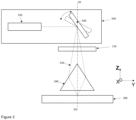
figure 1 illustrates a side view of a marking device for a MLI/CLI of a document with a prism according to the present invention, -
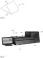
figure 2 illustrates a view of one embodiment of a personalization device comprising a personalisation module according to the present invention, -
figure 3 illustrates a side view of a marking of a MLI/CLI with a personalization module according to the present invention, with two positions of the scanning mirror, -
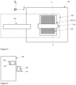
figure 4 illustrates a top view of a marking of a MLI/CLI with a personalization module according to the present invention, -
figure 5 illustrates a top view of a resting position and a working position of a prism according to the present invention, -
figure 6 illustrates one embodiment of a prism according to the present invention, -
figure 7 illustrates a all-in-one personalization device comprising a personalization module according to the present invention, -
figure 8 illustrates one embodiment of a prism according to the present invention, -
figure 9 illustrates a side view of a marking of a MLI/CLI with a personalization module according to another embodiment of the present invention, with two positions of the scanning mirror. - For the sake of conciseness, the personalization module according to the present invention will be referred to as "personalization module". The insertion of a
document 200 in the personalization module or in a device comprising the personalization module according to the present invention can be automatic or manual. - It relates to a module for personalization of documents, used in any device or machine, and in particular relates to a stand-alone personalization module or device, including a desktop device where dimension optimisation is of particular interest.
- The personalization module 100 may further comprise a
casing 110, or be incorporated in an existingcasing 430, for instance as illustrated onfigure 2 , wherein the prism is not visible. - The personalization module 100 will be described as if based on a horizontal support, such as e.g. a table or a desktop.
- In one embodiment, the document personalization module 100 according to the present invention is configured to be able to operate paper documents and hybrid documents which comprise both paper and polycarbonate pages, such as passports, as well as full polycarbonate documents such as identity cards, driving licenses, etc. within the same module or device.
- It offers a wide range of personalization options, preferably all complying e.g. with ICAO 9303 standards. As further described, the personalization module 100 can be integrated as a modular element in a device comprising further personalization elements or modules, securing long-term personalization solution investment, particularly for secure passport issuance offices and centers.
- It can be adapted to all types and sizes of documents.
- The personalization module 100 comprises a longitudinal axis, here called Y-axis, along which documents are moved as described later.
-
Figure 2 illustrates another embodiment of acasing 430 preferably comprising at least one air vent (not illustrated), to vent alaser marking module 500 described here after. Thecasing 430 also advantageously comprises a fan (not illustrated). Thecasing 430 may further comprise a set of legs having an adjustable height, to compensate for any lack of horizontality. - All personalization elements of a
document 200 which are laser marked are on the same polycarbonate (PC) page. ID cards are usually personalized on both sides as both sides are made of PC. - The personalization module 100 can be integrated in a personalization device such as e.g. illustrated in
figure 2 . On the device offigure 2 , theprism 300 is not illustrated. It is located inside theinkjet printing module 400, underneath thelaser marking module 500. The personalization device offigure 2 is preferably a front operated system withmanual document 200 insertion and retrieval, or an automated system, thanks to a very precise moving tray of a transport mechanism, aimed at handling thedocument 200 within the device according to the invention, to ensure high-precision movement for high-quality personalization. - The personalization module 100 comprises a
laser marking module 500 comprising alaser marking head 530. - In operation, on the working position MP, the
prism 300 is located above the page ofdocument 200 to be personalized. - The
laser marking module 500 can be located above thedocument 200 to be personalized, as illustrated infigure 2 , or distant from the page ofdocument 200 to be personalized, as illustrated onfigure 7 . - The
laser marking head 530 is configured to mark predetermined areas of a polycarbonate page (and/or certain types of paper) of a passport within a marking zone - or indistinctively area - where, by "marking", it is understood any of the following processes: marking, engraving, color change / blackening / bleaching, carbonization, ablation. - Typically, the size of the marking zone is inferior or equal to the size of the page of a passport, especially a polycarbonate page.
- Predetermined marking areas correspond typically to predetermined identification zones of the document body such as, for instance, the MRZ, portrait of its holder, his or her name, date of birth, a MLI or a CLI etc.
- The
laser head 530 is stationary. - In one embodiment, the
laser head 530 is adjacent to the printing bridge of the optionalinkjet printing module 400 described later, such that the marking zone and the printing zone are at least partly combined. - The
laser head 530 can be located above theinkjet printing module 400, as illustrated infigure 2 . In this case, thelaser beam 520 from thelaser head 530 of thelaser marking module 500 can go through anopening 131 made in a horizontalrigid plate 130 of thecasing 430 between thelaser marking module 500 and theinkjet printing module 400. - The
laser marking module 500, which comprises thelaser head 530, can mark any of the predetermined areas thanks to a laser scanner, which comprises a set of at least onetiltable mirror 540 and associated driver(s), e.g. piezoelectric driver(s). For this reason, the laser module is indistinctively considered as the laser scanner. - Accordingly, it is possible to mark the MRZ and all personalization data except the MLI/CLI, directly with the laser scanner. MRZ position is defined by ICAO standards. But personalization data can be located anywhere on a
document 200. Thelaser beam 520 can be directed anywhere on thedocument 200; it is positioned thanks to the mirrors of the laser scanner to mark directly personalization data in corresponding predetermined area(s), meaning with no optical means between the mirrors of the laser scanner and thedocument 200. - For marking a MLI/CLI, a
prism 300 described later is required/needed. - The
laser head 530 is configured to perform all types of marking while the tray is positioned under thelaser marking module 500 such as: - High definition gray scale picture(s) including ghost image,
- Thin high definition text including OCR-B for MRZ, and other fonts & characters used for captions and personalization data,
- Barcodes,
- Tactile personalization elements,
- Thin to bold texts according to specification.
- For CLI/MLI elements there is relative movement of the
prism 300 and thedocument 200 such that theprism 300 is located right above the CLI/MLI to be marked in the working position. - Further, the
prism 300 may adopt: - a first position relative to the CLI/MLI to be marked on the
document 200, to mark the first image element, and - a second position relative to the CLI/MLI to be marked on the
document 200, to mark the second image element. - One of the at least three following different laser sources can be implemented:
- 10W DPSS (Diode-pumped solid-state) laser source,
- 3W DPSS laser source, and
- 20W DPSS laser source.
- Other laser sources technologies can be implemented such as e.g. fibre laser sources. Such flexibility provided scalable performance while ensuring the exact same result in terms of marking quality and characteristics.
- Typically, the
laser head 530 emits a laser horizontal beam, parallel to the plane of thedocument 200. Thelaser beam 520 from thelaser head 530 is directed to tiltable scanning mirrors 540 of the laser scanner, the movement of which allowing to cover the area of thedocument 200, as illustrated onfigure 3 . - On
figure 3 , scanning mirrors 540 adopt a first position (in plain lines) to mark the first image element of a CLI/MLI; and a second position (in dashed lines) to mark the second image element of a CLI/MLI, such that thelaser beam 520 can be diverted to one side or the other of theprism 300. - On
figure 3 , scanning mirrors 540 are located on the axis of symmetry OS of theprism 300. - In another embodiment illustrated on
figure 9 , scanning mirrors 540 are shifted from the axis of symmetry OS of theprism 300. - Scanning mirrors 540 are located above the
array 210 of cylindrical lenticular lenses, in line with the MLI/CLI to be engraved, as illustrated onfigure 4 . - Preferably, scanning mirrors 540 are plane mirrors. Typically, they can be part of a on-the-shelf laser scanner. They can be tilted at least around a horizontal axis, which is preferably located in line with the middle of the
array 210 of cylindrical lenticular lenses. - According to the invention, the
laser marking module 500 may be a stand-alone module comprising acasing 110, which can be fixed e.g. with screws to anothercasing 430, allowing thelaser marking module 500 to be secured within thecasing 110 but being nonetheless removable in times of need. Accordingly, thelaser marking module 500 is interchangeable with anotherlaser marking module 500, for example if there is a need for a more powerful laser. - The
laser marking module 500 advantageously comprises a communication module, configured to enable a communication between thelaser marking module 500 and a remote computer comprising a display screen. Preferably, the communication module comprises a USB communication port. - Preferably, neither the
laser marking module 500 nor the laser marking head can be moved in translation along the Y-axis or the X-axis, which is perpendicular to the Y-axis in a horizontal plane. - The
laser marking module 500 may comprise anair vent 510, the position of which preferably corresponding to the position of the air vent of thecasing 430. - Where the
laser beam 520 can directly mark the MRZ, for marking the MLI/CLI it is necessary to mark a predetermined area through cylindrical lenticular lens of the MLI/CLI. A MLI/CLI comprises 2 image elements: a first image element in contact with a second image element. The first image element of a MLI/CLI is marked with thelaser beam 540 having a first angle of incidence on a given cylindrical lenticule and the second image element of the MLI/CLI is marked with thelaser beam 540 having a second angle of incidence on said cylindrical lenticule, as illustrated onfigure 3 orfigure 9 . - To this end, the laser scanner alone is not sufficient, it is necessary to modify the optical path of the
laser beam 520. - Contrary to the mentioned prior art which implements reflective means, the present invention advantageously implements here refractive means, in this case an optical prism, here after "prism", which is described here after.
- According to the present invention, the personalization module 100 comprises an
optical prism 300, here after "prism". - The
prism 300 is isosceles and has a rectangular shaped base which is configured to be parallel to thedocument 200, which is parallel to thelenticular array 210, as illustrated onfigure 1 . - In one embodiment the
prism 300 is atriangular prism 300. - More precisely, in the embodiment illustrated on
figure 1 ,figure 3 andfigure 6 , theprism 300 is a right isoscelestriangular prism 300, presenting an angle of 90° at the top, also called the apex, of theprism 300. - In one embodiment, not illustrated, the
prism 300 is a truncated triangular prism. - In one embodiment, not illustrated, the
prism 300 is a 4 faces pyramidal shapedprism 300. - In one embodiment, illustrated on
figure 8 , theprism 300 is a truncated 4 faces pyramidal shapedprism 300, presenting a rectangular shapedbase 320 which is parallel to thedocument 200. - When the prism is truncated, the top of the
prism 300 is preferably flat, and preferably parallel to its base. Advantageously, when the prism is truncated, the top of theprism 300 can be used as a surface of contact with a transport means. - Advantageously with a 4 faces pyramidal shaped, even truncated, it is possible to implement the same prism for both a CLI and a MLI without rotating the prism, as 2 opposite faces can be used for marking a CLI and the 2 other opposite faces can be used for marking a MLI.
- Preferably, the rectangular shaped base presents a surface which is greater than or equal to the surface of the
array 210 of cylindrical lenticular lenses. - It can be provided that the width of the
prism 300 is wider than the width of thelenticular array 210. - At its top, the
prism 300 has anedge 310 which is preferably located in line with the middle of thelenticular array 210. - Preferably, the
edge 310 of theprism 300 is elongated along a direction which is parallel to thelenticular array 210 main direction of elongation. - Preferably, the vertical distance between the
edge 310 of theprism 300 and thelaser head 530, is less than a predefined threshold. - The distance between the tiltable scanning mirrors 540 of the laser scanner and the prism can be small, e.g. between 10 cm and 20 cm, the personalization module 100 can be particularly compact in size.
- Preferably, the vertical distance between the
lenticular array 210 and the rectangular shapedbase 320, or bottom, of theprism 300 is less than a predefined threshold, in this case less than 20 mm. - Preferably, the
prism 300 is movable. - Typically, by default the
prism 300 is placed in a resting position RP, away from the MLI zone or the CLI zone, and away from thedocument 200, in order to protect it from inkjet droplets or any other polluting source. For marking the CLI/MLI of thedocument 200, theprism 300 is then moved to a working position MP, or marking position, over the MLI zone or the CLI zone. - In one embodiment, the
prism 300 is movable over thedocument 200 in a plane which is parallel to saiddocument 200, alongside at least one of the X-axis and the Y-axis. Accordingly, the position of theprism 300 is adaptable to various sorts of document 200 (for instance a standard passport and a diplomatic passport, etc.), wherever the MLI/CLI is located. - Further, the
document 200 may be moved relatively to theprism 300 in a horizontal plane, for instance for even more precise marking of the first image element and the second image element of the CLI/MLI. - In one embodiment, the
prism 300 is movable over thedocument 200 in a vertical direction. - Movements of the
prism 300 in a horizontal direction, in a horizontal plane or in the vertical direction can be implemented with help of a respective micro stepper motor, leading to a fine tuning of the position of theprism 300, as low as a tenth of a millimeter. - In one embodiment, the
prism 300 can be rotated, in this case over a horizontal direction parallel to the X-axis. Theprism 300 can also be rotated with a vertical axis of rotation, as illustrated onfigure 5 . Such rotation can be useful to change from a MLI marking to a CLI marking and also to put the prism in a safe area /rest position when not in use. - It can be provided that two or more of the previous embodiments relating to the movements of the
prism 300 are combined. - Thanks to the present invention, a same personalization module 100 can be implemented for a first type of
document 200 comprising a CLI and a second type ofdocument 200 comprising a MLI, for instance a passport and ID card. - Rotating the
prism 300 allows thesame prism 300 to be used for both CLI and MLI (generally lenticules main direction for CLI is perpendicular to lenticular grating main direction for MLI). - It can also be provided that the personalization module 100 comprises two
prisms 300, afirst prism 300 configured to engrave a MLI, and asecond prism 300 configured to engrave a CLI. - In one embodiment, at least the two faces of the
prism 300 adjacent to the base 320 are coated with anti-reflective coating, leading to almost no reflection of thelaser beam 520. - In operation, the
laser beam 520 is deflected by the mirrors of the laser scanner on one side of theprism 300 or on the opposite side of theprism 300 to mark respectively a first image element and a second image element of the MLI/CLI, as illustrated onfigure 1 andfigure 3 . - Thanks to the present invention, there is no need to tilt the
document 200 to mark the MLI/CLI area. Further, there is no need for mirrors dedicated to engraving a tilt image. - Accordingly, there is a full flexibility in positioning of the MLI/CLI on a
document 200. - The present invention allows different tilt image positions in the same personalization module 100, configurable with the layout.
- A same personalization module 100 can mark both CLIs and MLIs of different documents with a same device.
- Compared with a set of several mirrors of the mentioned prior art, the present invention relies advantageously on a
prism 300, which is a unique, one-piece, element. Accordingly, only one unique optical system is enough to ensure the setting of two engraving directions of thelaser beam 520. - Further, as the
prism 300 presents a plane base parallel to the plane of thedocument 200, the prism can be nearer to the document than the mirrors of the prior art, leading to a compact device. - The laser beam is refracted by the lateral faces of the
prism 300. In one embodiment it can be incident on the prism at an angle equal to the Brewster angle so that all the light is refracted. Accordingly, there is no reflection, which optimises the energy. - In one embodiment, the
prism 300 has the following geometrical dimensions: angle of 90° at its top, angles of 45° between the sides and the base. - The personalization module 100 can comprise a
shutter 120. - In one embodiment, the
shutter 120 is movable over thedocument 200 in a plane which is parallel to saiddocument 200, alongside at least one of the X-axis and the Y-axis. - Movements of the
shutter 120 can be implemented with help of a micro stepper motor, a standard motor or an actuator, as the need for a fine tuning of the position of theshutter 120 is not as strong as the need for a fine tuning of the position of theprism 300. - In one embodiment, the
shutter 120 can be rotated, or flipped over a horizontal direction parallel to the X-axis, like a flap. Theshutter 120 can also be rotated over a vertical direction. - The movement of the
shutter 120 may be combined with the movement of theprism 300. - In one embodiment, when the
prism 300 is in its resting position RP, theshutter 120 is closed and protects theprism 300, especially from dust and form ink droplets when the personalization module 100 further comprises aninkjet printing module 400, described hereafter. - In one embodiment, illustrated on
figure 2 , the personalization module 100 comprises aninkjet printing module 400, which comprises a moveable printing head mounted on a fixed printing bridge. The printing head is movable alongside the X-axis linear direction. - The printing head can adopt at least the 3 following positions:
- A printing position, where the printing head is configured to print within a printing zone,
- A printhead purge position, where the printing head can be purged, and
- A parking position, where the printing head can be parked, and where the inkjet cartridges are located.
- The printing operation is implemented with a plurality of printing positions as a tray supporting the
document 200 moves along the Y-axis linear direction during the printing operation. - Preferably, the printing head is connected to color and black inkjet cartridges. It is configured to print on any or both of page 2 and page 3 of a
document 200. Said colors can be within the visible spectrum, the UV spectrum, the IR spectrum, or any combination thereof. Inkjet cartridges are accessible through anaccess 410. - The printing head is configured to print within predetermined printing areas of any paper page, and optionally in addition on a polycarbonate page, of a
document 200 within a printing zone. Typically, the size of the printing zone is inferior or equal to the size of the paper page of adocument 200. - Predetermined printing areas correspond typically to predetermined identification zones of the
document 200 holder such as, for instance, the MRZ, his or her portrait, his or her name, date of birth, etc. - The
inkjet printing module 400 comprises a substantially flat horizontal surface on which a transport mechanism, the printing bridge and a flattening mechanism, are mounted. - In one embodiment, the
inkjet printing module 400 is based on an existing printer, such as the Hiprint™ P4000, produced by the applicant, which comprises a flattening mechanism; and from which the top of thecasing 430 is removed. For those starting with 'paper only' booklet and upgrading to 'paper and polycarbonate' at a later stage, it is possible that such Hiprint™ P4000 printer can be reused within the proposed personalization module 100, allows transitioning frompaper document 200 topolycarbonate document 200 with a smooth investment. Such printer offers high quality printing (up to 4800 dpi) for paper booklets personalization. It does include a 4-color inkjet printing head, which can easily be hot swapped by an operator. - Advantageously, the transport mechanism of the personalization module 100 is the transport mechanism of the
inkjet printing module 400, which can be an existing inkjet printer as exposed above. Accordingly, theinkjet printing module 400 comprises thedocument 200 transport mechanism. - In one embodiment, a transport mechanism is configured to automatically transport a
document 200 along a Y-axis linear direction, from an entrance to anexit 140 of the personalization module 100, wherein the entrance and theexit 140 are the same. The personalization module 100 is then a front-operated manual feeder, for bothdocument 200 insertion and retrieval. - In one embodiment, a transport mechanism comprises a tray on which the
document 200 is placed for marking / printing. The tray may be moved along guide bars, which is a high precision mechanism know in itself allowing highly precise positioning of the tray. - Preferably, the tray is provided with secure handle, ensuring
proper document 200 positioning. - In one embodiment, a transport mechanism comprises a set of at least one clamp to clamp the
document 200 open for printing and marking. - In one embodiment, a transport mechanism is configured to transport the
document 200 to the printing position and to a marking position, which is different from the printing position. - In one embodiment, a
document 200 transport mechanism is configured to transport adocument 200 to the printing positions and the marking position with thedocument 200 having its spine parallel to the X-axis linear direction, typically when thedocument 200 is a passport. - Embodiments may be combined.
- The
inkjet printing module 400 is accessible through a flap within thecasing 430, preferably equipped with ahandle 150. The opening of the flap, e.g. via a handle, enables access to theinkjet printing module 400, e.g. for its repair or replacement. Accordingly, the personalization module 100 is modular. The size of the flap is bigger than the size of theinkjet printing module 400. - Preferably, for safety reasons, the opening of the flap shuts off the power to the laser marking head, for instance with a sensor acting as a circuit breaker.
- In one embodiment the flap further comprises a manual hatch (not illustrated), the size of which being bigger than the size of a
document 200, to enable manual insertion of adocument 200 in theinkjet printing module 400 through that flap. - Preferably, the opening of the hatch shuts off the power to the laser marking head. Opening the hatch allows the operator to insert a
document 200 without having to open the flap. In such a case, the flap can be open just for maintenance reasons, such as e.g. change of the inkjet cartridges. The hatch allows an operator to insert and retrieve adocument 200 with just a movement of his hands, which is better in terms of ergonomics than manipulating the flap, which requires an additional movement of the shoulder. - According to the invention, the
inkjet printing module 400 is a stand-alone module fixed within thecasing 430, e.g. with screws, allowing theinkjet printing module 400 to be secured within thecasing 430 but being nonetheless removable in times of need. Accordingly, theinkjet printing module 400 is interchangeable with anotherinkjet printing module 400. - The
inkjet printing module 400 comprises a communication module, configured to enable a communication between theinkjet printing module 400 and a remote computer comprising a display screen. - Preferably, the
inkjet printing module 400 may comprise adisplay screen 420, e.g. a LCD screen, which is driven by the mother card of theinkjet printing module 400, and which allows to display maintenance information, like e.g. the level of ink left. - The personalization module 100 may comprise a vision system, comprising a camera, aimed at ensuring personal data positioning (offset registration).
- In addition, it can as well ensure element detection (i.e. OCR) and automated quality control at the end of the personalization process.
- The vision system may be used for several purpose:
-
Document 200 proper introduction and orientation verification (specific element detection), -
Document 200 ID retrieval, - Printing / marking image repositioning (offset positioning) to ensure a perfect printing zone position,
- Page 2 and/or page 3 graphical area snapshot for post-personalization quality control, data consistency check, and personalization characteristics verification,
- Page 2 and/or page 3 snapshot to store
document 200 final image into a database. - The camera is particularly configured to detect the position of the
document 200 once positioned on a transport mechanism. It is also configured to drive at least one of theinkjet printing module 400 and thelaser marking module 500 according to a comparison of said position with a reference position. - The camera can detect the position of the
document 200, i.e. which of page 2 and page 3 enters first. If the position of thedocument 200 is improper, a warning message can be triggered, a transport mechanism can be automatically reversed to eject thedocument 200, or any other suitable operation. - Preferably, the personalization module 100 further comprises a detection system, e.g. a presence sensor, typically an optical sensor such as a photocell, or any other detection mechanism to detect the entrance of a
document 200 into the personalization module 100 or into a transport mechanism. - Preferably, the camera is close to the laser marking head, where "close" means at a distance inferior to a predetermined value. It is worth noting that several cameras may be provided, e.g. one for the offset registration and one for the
document 200 position detection. - Preferably, the angle between the optical axis of the camera for the offset registration and the
laser beam 520 of the laser marking head is inferior or equal to a predetermined value, here inferior or equal to 10°. - The vision system comprises a communication module, configured to enable a communication between the camera and a remote computer comprising a display screen. Preferably, the communication module comprises a USB communication port.
- In one embodiment, a camera of the vision system is located in the
casing 430 above theinkjet printing module 400, adjacent to thelaser marking module 500. The optical axis of the camera goes through anopening 132 made in the horizontal rigid plate, adjacent to theopening 131, as illustrated onfigure 2 . - The personalization module 100 may comprise a chip encoding module 600 (
figure 7 ), configured to read and to encode a chip comprised within thedocument 200, especially when thedocument 200 is a passport. - Typically, the chip is a RFID chip, thus the chip encoding module is an RFID encoding module comprising a RFID antenna. More precisely, the RFID module is based on a set including reader electronics and a separate antenna preferably complying with ICAO 9303 requirements.
- In one embodiment, the chip encoding module is comprised in the
inkjet printing module 400. - In one embodiment, the RFID antenna is located under the tray of the transport mechanism. Thanks to the antenna position, once the booklet is inserted in the personalization module 100, it is possible to establish a communication with the chip, and therefore to start encoding whatever the other operations in progress are. Typically, it is possible to encode while printing and/or marking, which allows significant time saving during the entire personalization process.
- Advantageously, the chip encoding module is integral with the
document 200 transport mechanism. Accordingly, the chip of thedocument 200 can be encoded while thedocument 200 is being transported from a position to another, both reducing the time of personalization and compacting the personalization module 100. This allows parallel encoding while printing, speeding-up the whole personalization process for more production throughput and efficiency. - In one embodiment, the personalization module 100 is a stand-alone desktop personalization device.
- The
chip encoding module 600 comprises a communication module, configured to enable a communication between said chip encoding module and a remote computer comprising a display screen, as illustrated onfigure 7 . - Preferably, the communication module of the chip encoding module is the same than the communication module of the
inkjet printing module 400. - One only communication module can be provided for the vision system, the
laser marking module 500, theinkjet printing module 400 and the chip encoding module. -
- 100
- personalization module
- 110
- Casing of the personalization module
- 120
- Shutter
- 130
- Horizontal rigid plate
- 131
- opening (for the laser head 530)
- 132
- opening (for a camera)
- 140
- entrance and exit of the personalization module
- 150
- handle
- 200
-
Document 200 - 210
- Array of lenticular lenses
- A-A
- Lenticular array main direction of elongation
- 300
- Optical prism
- 310
- Edge/top/apex of the prism
- 320
- Base of the prism
- RP
- Resting position
- MP
- Working/Marking position
- OS
- optical axis of symmetry of the
prism 300 - 400
- Inkjet printing module
- 410
- Access to inkjet cartridges
- 420
- Display screen
- 430
- casing of the inkjet printing module
- 500
- Laser marking module
- 510
- air vent
- 520
- Laser beam
- 530
- laser head
- 540
- scanning mirror(s), for two-axis driving of the laser beam
- 600
- chip encoding module
Claims (15)
- Personalization module (100), for personalization of a security document (200), said document (200) comprising a marking area for marking a two-image element MLI or CLI through an array (210) of lenticular lenses having a main direction of elongation, said personalization module (100) comprising:- a laser marking module (500), configured to mark within a marking zone, and comprising a laser head (530) configured to emit a laser beam (520), and a laser scanner equipped with movable mirrors to deflect said laser beam (520) towards said document (200),Characterized in that it further comprises:- An optical prism (300), configured to refract the laser beam (520) from the laser scanner mirrors to the lenticular lenses, one side of the prism (300) enabling marking a first image element of the MLI or the CLI, the other side of the prism (300) enabling marking a second image element of the MLI or the CLI.
- Personalization module (100) according to claim 1, further comprising a set of at least one transport mechanism, said set being configured to implement at least one of the following movements:- transport a security document (200) along a Y-axis linear direction, from an entrance to an exit (140) of the desktop personalization module (100), through a marking position (MP),- move the prism (300) at least in a horizontal plane, alongside at least one of the X-axis and the Y-axis.
- Personalization module (100) according to claim 2, wherein the set of at least one transport mechanism is further configured to move the prism (300) at least in a vertical direction.
- Personalization module (100) according to any of claim 2 or 3, wherein the set of at least one transport mechanism is configured to move the prism (300) form a resting position (RP) to a working position (MP), where when viewed from above, the prism (300) is away from the marking zone in the resting position (RP) and over the marking zone in the working position (MP).
- Personalization module (100) according to any of claims 2 to 4, wherein the set of at least one transport mechanism comprises rotating means to rotate the position of the prism (300) in a horizontal plane.
- Personalization module (100) according to any of claims 2 to 5, comprising at least one motor per movement of the prism (300).
- Personalization module (100) according to any of the preceding claims, wherein the prism (300) comprises at least two faces where the laser beam (520) is incident, said faces being coated with anti-reflective coating.
- Personalization module (100) according to any of the preceding claims, wherein the prism (300) is isosceles and has a rectangular shaped base which is configured to be parallel to the document (200).
- Personalization module (100) according to claim 8, wherein the prism (300) presents an axis of symmetry which is elongated along a direction which is parallel to the lenticular array (210) main direction of elongation.
- Personalization module (100) according to any of the preceding claims, further comprising a shutter (120).
- Personalization module (100) according to claim 10, wherein the shutter (120) is movable over the document (200) in a plane which is parallel to said document (200), the movement of the shutter possibly being a translation, a rotation or a combination of both a translation and a rotation.
- Personalization module (100) according to any of the preceding claims, further comprising:- an inkjet printing module (400), comprising a moveable printing head being configured to print within a printing zone of the document (200).
- Personalization module (100) according to any of the preceding claims, further comprising a vision system, comprising a camera, aimed at ensuring at least one of the following:- the laser beam positioning;- the document positioning;- the markings position / quality;- the printing.
- Personalization module (100) according to any of the preceding claims, further comprising a chip encoding module, configured to read and to encode a chip comprised within the document (200).
- Personalization module (100) according to any of claim 8 to 14, wherein the prism (300) presents one of the following shapes:- a triangular prism (300);- a right isosceles triangular prism (300) presenting an angle of 90° at its top;- a truncated triangular prism (300);- a 4 faces pyramidal shaped prism (300); and- a 4 faces truncated pyramidal shaped prism (300).
Priority Applications (4)
| Application Number | Priority Date | Filing Date | Title |
|---|---|---|---|
| ES22215166T ES3038262T3 (en) | 2022-12-20 | 2022-12-20 | Personalization module for security documents |
| EP22215166.4A EP4389448B1 (en) | 2022-12-20 | 2022-12-20 | Personalization module for security documents |
| PCT/EP2023/086049 WO2024132925A1 (en) | 2022-12-20 | 2023-12-15 | Personalization module for security documents |
| MX2025007151A MX2025007151A (en) | 2022-12-20 | 2025-06-18 | Personalization module for security documents |
Applications Claiming Priority (1)
| Application Number | Priority Date | Filing Date | Title |
|---|---|---|---|
| EP22215166.4A EP4389448B1 (en) | 2022-12-20 | 2022-12-20 | Personalization module for security documents |
Publications (2)
| Publication Number | Publication Date |
|---|---|
| EP4389448A1 true EP4389448A1 (en) | 2024-06-26 |
| EP4389448B1 EP4389448B1 (en) | 2025-05-28 |
Family
ID=84547173
Family Applications (1)
| Application Number | Title | Priority Date | Filing Date |
|---|---|---|---|
| EP22215166.4A Active EP4389448B1 (en) | 2022-12-20 | 2022-12-20 | Personalization module for security documents |
Country Status (4)
| Country | Link |
|---|---|
| EP (1) | EP4389448B1 (en) |
| ES (1) | ES3038262T3 (en) |
| MX (1) | MX2025007151A (en) |
| WO (1) | WO2024132925A1 (en) |
Citations (3)
| Publication number | Priority date | Publication date | Assignee | Title |
|---|---|---|---|---|
| EP0219012A2 (en) * | 1985-10-15 | 1987-04-22 | GAO Gesellschaft für Automation und Organisation mbH | Data carrier with an optical authenticity feature, and method of making and checking the data carrier |
| US20010028390A1 (en) * | 1997-09-26 | 2001-10-11 | Sumitomo Heavy Industries, Ltd., A Japanese Corporation | Method for making marks in a transparent material by using a laser |
| EP2050574A1 (en) | 2007-09-27 | 2009-04-22 | FOBA Technology & Services GmbH | Method and device for scribing a kinegram structure |
-
2022
- 2022-12-20 ES ES22215166T patent/ES3038262T3/en active Active
- 2022-12-20 EP EP22215166.4A patent/EP4389448B1/en active Active
-
2023
- 2023-12-15 WO PCT/EP2023/086049 patent/WO2024132925A1/en not_active Ceased
-
2025
- 2025-06-18 MX MX2025007151A patent/MX2025007151A/en unknown
Patent Citations (3)
| Publication number | Priority date | Publication date | Assignee | Title |
|---|---|---|---|---|
| EP0219012A2 (en) * | 1985-10-15 | 1987-04-22 | GAO Gesellschaft für Automation und Organisation mbH | Data carrier with an optical authenticity feature, and method of making and checking the data carrier |
| US20010028390A1 (en) * | 1997-09-26 | 2001-10-11 | Sumitomo Heavy Industries, Ltd., A Japanese Corporation | Method for making marks in a transparent material by using a laser |
| EP2050574A1 (en) | 2007-09-27 | 2009-04-22 | FOBA Technology & Services GmbH | Method and device for scribing a kinegram structure |
Also Published As
| Publication number | Publication date |
|---|---|
| EP4389448B1 (en) | 2025-05-28 |
| MX2025007151A (en) | 2025-07-01 |
| WO2024132925A1 (en) | 2024-06-27 |
| ES3038262T3 (en) | 2025-10-10 |
Similar Documents
| Publication | Publication Date | Title |
|---|---|---|
| EP1277589B1 (en) | A manually positioned printer with an alignment means | |
| CN1153682C (en) | Passport production system and method | |
| US9904876B2 (en) | Modular print engines and modular print engine components | |
| EP3274188B1 (en) | Method of providing an imprinted security feature | |
| US3858797A (en) | Inspection device in card readers | |
| AU613959B2 (en) | Document handling apparatus | |
| US20190135016A1 (en) | System and Method for Laser Writing | |
| CN103448378B (en) | Laser marker | |
| EP4389448B1 (en) | Personalization module for security documents | |
| US12227014B2 (en) | Automatic desktop personalization device for booklet documents | |
| CA3027467A1 (en) | Printer for official documents | |
| WO2019171104A1 (en) | A desktop apparatus for personalizing of plastic cards | |
| CN113688963B (en) | Laser Endorsement System | |
| KR20100065163A (en) | Apparatus and method for writing a flip image structure | |
| CN111098020A (en) | Personalized configuration device and method for plastic cards | |
| JPS6016763A (en) | Printer | |
| RU2767026C1 (en) | Unit for moving and positioning the card for laser and/or electronic personalization | |
| RU2759089C1 (en) | Card rotation module for personalization | |
| GB2175854A (en) | Supporting plate arrangement for document printers | |
| US11731445B2 (en) | Laser marking warpage mitigation | |
| US20210086546A1 (en) | Device and method for recording information in a data carrier | |
| US20220111662A1 (en) | Handheld printing device with light source to project light box | |
| EP1001599A2 (en) | Printer with scanner | |
| US4094601A (en) | Reproduction of paged material from microform cards | |
| JP5141178B2 (en) | Image reading apparatus and image inspection method |
Legal Events
| Date | Code | Title | Description |
|---|---|---|---|
| PUAI | Public reference made under article 153(3) epc to a published international application that has entered the european phase |
Free format text: ORIGINAL CODE: 0009012 |
|
| STAA | Information on the status of an ep patent application or granted ep patent |
Free format text: STATUS: REQUEST FOR EXAMINATION WAS MADE |
|
| 17P | Request for examination filed |
Effective date: 20221220 |
|
| AK | Designated contracting states |
Kind code of ref document: A1 Designated state(s): AL AT BE BG CH CY CZ DE DK EE ES FI FR GB GR HR HU IE IS IT LI LT LU LV MC ME MK MT NL NO PL PT RO RS SE SI SK SM TR |
|
| GRAP | Despatch of communication of intention to grant a patent |
Free format text: ORIGINAL CODE: EPIDOSNIGR1 |
|
| STAA | Information on the status of an ep patent application or granted ep patent |
Free format text: STATUS: GRANT OF PATENT IS INTENDED |
|
| RIC1 | Information provided on ipc code assigned before grant |
Ipc: B42D 25/41 20140101AFI20250204BHEP |
|
| INTG | Intention to grant announced |
Effective date: 20250218 |
|
| GRAS | Grant fee paid |
Free format text: ORIGINAL CODE: EPIDOSNIGR3 |
|
| GRAA | (expected) grant |
Free format text: ORIGINAL CODE: 0009210 |
|
| STAA | Information on the status of an ep patent application or granted ep patent |
Free format text: STATUS: THE PATENT HAS BEEN GRANTED |
|
| AK | Designated contracting states |
Kind code of ref document: B1 Designated state(s): AL AT BE BG CH CY CZ DE DK EE ES FI FR GB GR HR HU IE IS IT LI LT LU LV MC ME MK MT NL NO PL PT RO RS SE SI SK SM TR |
|
| REG | Reference to a national code |
Ref country code: GB Ref legal event code: FG4D |
|
| REG | Reference to a national code |
Ref country code: CH Ref legal event code: EP |
|
| REG | Reference to a national code |
Ref country code: IE Ref legal event code: FG4D Ref country code: DE Ref legal event code: R096 Ref document number: 602022015184 Country of ref document: DE |
|
| REG | Reference to a national code |
Ref country code: NL Ref legal event code: FP |
|
| PG25 | Lapsed in a contracting state [announced via postgrant information from national office to epo] |
Ref country code: FI Free format text: LAPSE BECAUSE OF FAILURE TO SUBMIT A TRANSLATION OF THE DESCRIPTION OR TO PAY THE FEE WITHIN THE PRESCRIBED TIME-LIMIT Effective date: 20250528 |
|
| REG | Reference to a national code |
Ref country code: LT Ref legal event code: MG9D Ref country code: ES Ref legal event code: FG2A Ref document number: 3038262 Country of ref document: ES Kind code of ref document: T3 Effective date: 20251010 |
|
| PG25 | Lapsed in a contracting state [announced via postgrant information from national office to epo] |
Ref country code: NO Free format text: LAPSE BECAUSE OF FAILURE TO SUBMIT A TRANSLATION OF THE DESCRIPTION OR TO PAY THE FEE WITHIN THE PRESCRIBED TIME-LIMIT Effective date: 20250828 Ref country code: GR Free format text: LAPSE BECAUSE OF FAILURE TO SUBMIT A TRANSLATION OF THE DESCRIPTION OR TO PAY THE FEE WITHIN THE PRESCRIBED TIME-LIMIT Effective date: 20250829 |
|
| PG25 | Lapsed in a contracting state [announced via postgrant information from national office to epo] |
Ref country code: PL Free format text: LAPSE BECAUSE OF FAILURE TO SUBMIT A TRANSLATION OF THE DESCRIPTION OR TO PAY THE FEE WITHIN THE PRESCRIBED TIME-LIMIT Effective date: 20250528 |
|
| PG25 | Lapsed in a contracting state [announced via postgrant information from national office to epo] |
Ref country code: BG Free format text: LAPSE BECAUSE OF FAILURE TO SUBMIT A TRANSLATION OF THE DESCRIPTION OR TO PAY THE FEE WITHIN THE PRESCRIBED TIME-LIMIT Effective date: 20250528 |
|
| PG25 | Lapsed in a contracting state [announced via postgrant information from national office to epo] |
Ref country code: HR Free format text: LAPSE BECAUSE OF FAILURE TO SUBMIT A TRANSLATION OF THE DESCRIPTION OR TO PAY THE FEE WITHIN THE PRESCRIBED TIME-LIMIT Effective date: 20250528 |
|
| PG25 | Lapsed in a contracting state [announced via postgrant information from national office to epo] |
Ref country code: RS Free format text: LAPSE BECAUSE OF FAILURE TO SUBMIT A TRANSLATION OF THE DESCRIPTION OR TO PAY THE FEE WITHIN THE PRESCRIBED TIME-LIMIT Effective date: 20250828 |
|
| PG25 | Lapsed in a contracting state [announced via postgrant information from national office to epo] |
Ref country code: IS Free format text: LAPSE BECAUSE OF FAILURE TO SUBMIT A TRANSLATION OF THE DESCRIPTION OR TO PAY THE FEE WITHIN THE PRESCRIBED TIME-LIMIT Effective date: 20250928 |
|
| PG25 | Lapsed in a contracting state [announced via postgrant information from national office to epo] |
Ref country code: LV Free format text: LAPSE BECAUSE OF FAILURE TO SUBMIT A TRANSLATION OF THE DESCRIPTION OR TO PAY THE FEE WITHIN THE PRESCRIBED TIME-LIMIT Effective date: 20250528 |
|
| PGFP | Annual fee paid to national office [announced via postgrant information from national office to epo] |
Ref country code: NL Payment date: 20251119 Year of fee payment: 4 |
|
| REG | Reference to a national code |
Ref country code: AT Ref legal event code: MK05 Ref document number: 1798438 Country of ref document: AT Kind code of ref document: T Effective date: 20250528 |
|
| PGFP | Annual fee paid to national office [announced via postgrant information from national office to epo] |
Ref country code: DE Payment date: 20251126 Year of fee payment: 4 |
|
| PG25 | Lapsed in a contracting state [announced via postgrant information from national office to epo] |
Ref country code: AT Free format text: LAPSE BECAUSE OF FAILURE TO SUBMIT A TRANSLATION OF THE DESCRIPTION OR TO PAY THE FEE WITHIN THE PRESCRIBED TIME-LIMIT Effective date: 20250528 Ref country code: SM Free format text: LAPSE BECAUSE OF FAILURE TO SUBMIT A TRANSLATION OF THE DESCRIPTION OR TO PAY THE FEE WITHIN THE PRESCRIBED TIME-LIMIT Effective date: 20250528 Ref country code: DK Free format text: LAPSE BECAUSE OF FAILURE TO SUBMIT A TRANSLATION OF THE DESCRIPTION OR TO PAY THE FEE WITHIN THE PRESCRIBED TIME-LIMIT Effective date: 20250528 |
|
| PGFP | Annual fee paid to national office [announced via postgrant information from national office to epo] |
Ref country code: FR Payment date: 20251119 Year of fee payment: 4 |
|
| PG25 | Lapsed in a contracting state [announced via postgrant information from national office to epo] |
Ref country code: CZ Free format text: LAPSE BECAUSE OF FAILURE TO SUBMIT A TRANSLATION OF THE DESCRIPTION OR TO PAY THE FEE WITHIN THE PRESCRIBED TIME-LIMIT Effective date: 20250528 |
|
| PG25 | Lapsed in a contracting state [announced via postgrant information from national office to epo] |
Ref country code: EE Free format text: LAPSE BECAUSE OF FAILURE TO SUBMIT A TRANSLATION OF THE DESCRIPTION OR TO PAY THE FEE WITHIN THE PRESCRIBED TIME-LIMIT Effective date: 20250528 |
|
| PG25 | Lapsed in a contracting state [announced via postgrant information from national office to epo] |
Ref country code: SK Free format text: LAPSE BECAUSE OF FAILURE TO SUBMIT A TRANSLATION OF THE DESCRIPTION OR TO PAY THE FEE WITHIN THE PRESCRIBED TIME-LIMIT Effective date: 20250528 |
|
| REG | Reference to a national code |
Ref country code: DE Ref legal event code: R097 Ref document number: 602022015184 Country of ref document: DE |
|
| PG25 | Lapsed in a contracting state [announced via postgrant information from national office to epo] |
Ref country code: RO Free format text: LAPSE BECAUSE OF FAILURE TO SUBMIT A TRANSLATION OF THE DESCRIPTION OR TO PAY THE FEE WITHIN THE PRESCRIBED TIME-LIMIT Effective date: 20250528 |
|
| PLBE | No opposition filed within time limit |
Free format text: ORIGINAL CODE: 0009261 |
|
| STAA | Information on the status of an ep patent application or granted ep patent |
Free format text: STATUS: NO OPPOSITION FILED WITHIN TIME LIMIT |
|
| REG | Reference to a national code |
Ref country code: CH Ref legal event code: L10 Free format text: ST27 STATUS EVENT CODE: U-0-0-L10-L00 (AS PROVIDED BY THE NATIONAL OFFICE) Effective date: 20260409 |
|
| PGFP | Annual fee paid to national office [announced via postgrant information from national office to epo] |
Ref country code: ES Payment date: 20260102 Year of fee payment: 4 |
|
| PGFP | Annual fee paid to national office [announced via postgrant information from national office to epo] |
Ref country code: IT Payment date: 20251231 Year of fee payment: 4 |
|
| 26N | No opposition filed |
Effective date: 20260303 |