EP4389236A1 - Extincteur d'incendie courbé pour moteur - Google Patents
Extincteur d'incendie courbé pour moteur Download PDFInfo
- Publication number
- EP4389236A1 EP4389236A1 EP23215782.6A EP23215782A EP4389236A1 EP 4389236 A1 EP4389236 A1 EP 4389236A1 EP 23215782 A EP23215782 A EP 23215782A EP 4389236 A1 EP4389236 A1 EP 4389236A1
- Authority
- EP
- European Patent Office
- Prior art keywords
- fire extinguisher
- piston
- engine
- storage chamber
- aircraft engine
- Prior art date
- Legal status (The legal status is an assumption and is not a legal conclusion. Google has not performed a legal analysis and makes no representation as to the accuracy of the status listed.)
- Granted
Links
Images


Classifications
-
- A—HUMAN NECESSITIES
- A62—LIFE-SAVING; FIRE-FIGHTING
- A62C—FIRE-FIGHTING
- A62C3/00—Fire prevention, containment or extinguishing specially adapted for particular objects or places
- A62C3/07—Fire prevention, containment or extinguishing specially adapted for particular objects or places in vehicles, e.g. in road vehicles
- A62C3/08—Fire prevention, containment or extinguishing specially adapted for particular objects or places in vehicles, e.g. in road vehicles in aircraft
-
- A—HUMAN NECESSITIES
- A62—LIFE-SAVING; FIRE-FIGHTING
- A62C—FIRE-FIGHTING
- A62C35/00—Permanently-installed equipment
- A62C35/02—Permanently-installed equipment with containers for delivering the extinguishing substance
- A62C35/023—Permanently-installed equipment with containers for delivering the extinguishing substance the extinguishing material being expelled by compressed gas, taken from storage tanks, or by generating a pressure gas
Definitions
- the present invention relates to an engine fire extinguisher comprising an extinguishing agent.
- Extinguishing engine fires is a problem encountered in particular in the aeronautical field, for example when trying to extinguish the fire of an aircraft engine.
- Aircraft engine fire extinguishers are generally equipped with systems such as extinguishing agent bottles pressurized to around 200 bars. Such systems are maintained at a distance from the engine, outside the nacelle. Fire extinguishers are generally held in position by fixing elements and connected to the engine compartment by pipes, in order to limit the direct exposure of the extinguishers to the high thermal stresses of the engine environment.
- Halons typically use Halon gas as an extinguishing agent to suppress the oxygen to contain the fire.
- Halons have the advantage of ensuring satisfactory extinguishing while maintaining a reduced mass.
- Halons are polluting products, which have a high ozone depletion potential (“ODP” in English for “Ozone Depletion Potential”) and whose use is subject to increasingly strict regulatory bans.
- ODP ozone depletion potential
- the use of Halons as an extinguishing agent therefore constitutes an environmentally unsatisfactory provisional solution which should be replaced.
- Halons also have the disadvantage of having a high warming potential.
- This gaseous agent is stored in tanks positioned in the mast of each engine. Metal pipes are connected to it. They separate into several injection points in the upper part of the nacelle. The injection is therefore carried out in a non-targeted manner and drowns the entire engine.
- the object of the invention is to provide a pyrotechnic extinguisher using a non-polluting extinguishing agent in the liquid state which can be integrated into the nacelle of an engine to act as close as possible to the engine and thus extinguish a fire without drowning the engine and limit the masses of the accessories of the extinguisher as much as possible, but by limiting to a minimum the aerodynamic disturbances of the air flow circulating in the vein of the engine in which the extinguisher is integrated.
- the piston comprises the gas generator, and the body has a longitudinally curved shape between its first end and its second end, the piston having a curvilinear stroke between the first end and the second end of the body .
- the longitudinally curved shape of the body makes it possible to match the shape of the external wall of the vein where the extinguisher will be installed in the engine and thus to limit as much as possible the disruption of the air flow in the vein.
- the integration of the extinguisher into the engine's air flow thus makes it possible to maximize the effectiveness of the extinguishing and to reduce the volume of extinguishing agent necessary for the extinguishing.
- the gas generator By placing the gas generator in the piston, it is protected by the air or gas present in the pressurization chamber, which acts as a thermal insulator.
- the gas generator is therefore protected from thermal constraints external to the fire extinguisher by being interposed between a gaseous sky of the pressurizing chamber and the extinguishing agent of the storage chamber.
- the extinguishing agent has a strong endothermic power, which makes it an excellent thermal insulator.
- the fire extinguisher is very compact, and can be integrated as close as possible to the engine, which limits the number of fixings and pipes required, and thus lightens the entire device. In particular, such a fire extinguisher placed near the engine is still operational after 15 minutes of fire in the engine.
- the piston may have a shape without central symmetry, such as for example an oblong shape or a figure eight shape.
- the shape without central symmetry prevents any rotation of the piston around its axis and thus eliminates the risk of the piston getting stuck in the enclosure of the body.
- the piston may have a longitudinally curved profile corresponding to the longitudinal curvature of the body.
- the curved shape of the piston in the longitudinal direction makes it easier to slide the piston within the enclosure of the body in the longitudinal direction between the first end and the second end of the body.
- the body may include a plurality of exit ports.
- the plurality of outlet ports makes it possible to precisely target different areas of the engine, and fill the volume more quickly.
- the extinguisher may further comprise at least one injection rail coupled to an outlet orifice.
- the injection rail allows the extinguishing agent to be delivered more quickly to areas distant from the extinguisher without waiting for the cavity to be treated to be filled.
- At least one injection rail may comprise at least one tube pierced with a plurality of spray orifices.
- the tubes can have a circular section, square or another shape.
- each spray orifice of a tube is provided with a spray nozzle or an orifice acting as a nozzle.
- the piston may comprise a thermal insulation housing in which the gas generator is present, the housing being interposed between the pressurization chamber and the storage chamber, the housing opening into the pressurization chamber .
- the thermal insulation housing defines a projecting portion in the storage chamber and the gas generator is surrounded by the extinguishing agent.
- the housing in which the gas generator is present is in this case insulated on all its sides, thus further improving the resistance of the gas generator in a fire environment.
- the gas generator is a pyrotechnic gas generator.
- a pyrotechnic gas generator is advantageous compared to the use of a pressurized gas cylinder in order, on the one hand, to limit the sensitivity to the temperature of the pressure generated and, on the other hand, , to obtain an extinguishing agent pressure profile as a function of time making it possible to obtain extinguishing agent concentration values as a function of time as close as possible to the minimum necessary extinguishing agent concentration values, thus further improving the extinguishing efficiency in an engine environment.
- the invention further relates to an aircraft engine equipped with at least one fire extinguisher as described above.
- the engine is an aircraft engine comprising a nacelle, the fire extinguisher being integrated into the nacelle.
- At least one tube of an injection rail is fixed to the nacelle using metal supports and extends in the engine in a direction parallel to an axis of revolution of the engine.
- At least one tube of an injection rail can be fixed to the nacelle using metal supports and extend around the engine forming a ring.
- the invention also relates to a method of extinguishing a fire in an aircraft engine using at least one fire extinguisher as described above.
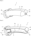
- THE figures 1 and 2 illustrate a perspective view and a sectional view of an example of fire extinguisher 1 according to a first embodiment of the invention.
- the fire extinguisher 1 comprises a body 2 extending longitudinally between a first end 2b and a second end 2c.
- the body 2 is hollow and forms an enclosure 2a enclosing a pressurization chamber 3 and a storage chamber 4.
- the body 2 also contains a piston 5, which separates the pressurization chamber 3 and the storage chamber 4.
- the enclosure 2a formed by the body 2 extends along the curvilinear longitudinal axis C figure 2 and surrounds the storage chamber 4 and the pressurization chamber 3.
- the piston 5 slides in the body 2 in contact with the enclosure 2a of said body 2.
- the body 2 further comprises a first bottom wall 21 at its first end 2b as well as a second bottom wall 22 at its second end 2c.
- the first and second bottom walls 2b and 2c define the body 2 longitudinally.
- the first bottom wall 21 delimits the pressurization chamber 3 while the second bottom wall 22 delimits the storage chamber 4, the pressurization chamber 3 and the storage chamber 4 being separated from each other. other by the piston 5.
- the pressurization chamber 3 is therefore located between the piston 5 and the first bottom wall 21.
- the storage chamber 4 is for its part located between the second bottom wall 22 and the piston 5. Consequently, the pressurization chamber 3 is delimited by the enclosure 2a of the body 2, by the first bottom wall 21 and by the piston 5, and the storage chamber 4 is delimited by the enclosure 2a of the body 2 , by the second bottom wall 22 and by the piston 5.
- the piston 5 is able to slide longitudinally in the body 2 between the first end 2b and the second end 2c.
- the sliding of the piston 5 in the body 2 makes it possible to vary the volume of the pressurization chamber 3 and of the storage chamber 4.
- the piston 5 can slide along a curvilinear axis of movement coincident with the axis longitudinal C X curvilinear of body 2.
- the second bottom wall 22 comprises an outlet orifice 10 configured to eject extinguishing agent outside the body 2.
- the second bottom wall 22 may comprise several outlet orifices 10.
- THE figures 3 and 4 respectively present a perspective view and a side view of the piston of the fire extinguisher 1 of the figures 1 and 2 .
- the piston 5 comprises a first wall 51 and a second wall 52 spaced from the first wall 51 and connected to the first wall 51 via a third wall 53 extending between the first wall 51 and the second wall 52.
- the piston 5 thus forms a closed polyhedron.
- the first wall 51 of the piston 5 faces the pressurization chamber 3 and faces the first bottom wall 21 of the body 2.
- the second wall 52 of the piston 5 faces the storage chamber 4 and faces of the second bottom wall 22 of the body 2.
- the piston 5 has a curved shape along the curvilinear longitudinal axis C
- the third wall 53 therefore does not have any notable symmetry.
- the portion of the third wall 53 which is at the bottom is shorter than the portion of the third wall 53 which is at the top when measuring the lengths of the portions between the first wall 51 and the second wall 52.
- the piston 5 in a section plane orthogonal to the direction of the curvilinear longitudinal axis C, the piston 5 has a shape without axial symmetry, and more particularly an overall shape of eight, that is to say pinched in the middle.
- This shape without axial symmetry in a cutting plane orthogonal to the curvilinear axis of movement of the piston 5 makes it possible to prevent the piston from getting stuck during its movement in the enclosure 2a.
- the piston 5 is configured to sealingly separate the pressurization chamber 3 from the storage chamber 4.
- the piston 5 extends over the entire internal section of the storage chamber 4.
- the piston 5 comprises preferably a sealing system 54 making it possible to create a seal between the pressurization chamber 3 and the storage chamber 4.
- the sealing system 54 prevents the extinguishing agent from penetrating into the pressurization chamber 3 , and prevents the air or gases present in the pressurization chamber 3 from penetrating inside the storage chamber 4.
- the sealing system 54 illustrated on the figures 3 and 4 comprises two seals 55 arranged continuously between the piston 5 and the body 2 and extending over the entire external perimeter of the third wall 53 to form a waterproof barrier in a plane perpendicular to the curvilinear longitudinal axis C
- the piston 5 can be made of metallic material, for example aluminum.
- the piston 5 can be made of a single material in order to simplify the manufacturing process of the fire extinguisher 1.
- a extinguishing agent is present in the storage chamber 4.
- the extinguishing agent may be present in the liquid state.
- the extinguishing agent may be present in the gaseous state.
- the extinguishing agent can be FK-5-1-12 or Novec TM 1230.
- Novec TM 1230 makes it possible to lower the temperature of the fire in the engine environment by vaporizing at the exit of the extinguisher and helps lower the oxygen level.
- Novec TM 1230 also has the advantage of being dielectric and leaving no residue.
- the fire extinguisher comprises a gas generator which can be housed in the piston 5 and in communication with the pressurization chamber 3 to generate the movement of the piston 5 towards the second end 2c of the body 2.
- the fire extinguisher 1 may further comprise a shutter sealingly closing the outlet orifice 10 and configured to allow the exit of the extinguishing agent outside the body 2 when the pressure in the storage chamber 4 exceeds a predefined value.
- the shutter is configured to prevent, when it is in a first configuration, the exit of the extinguishing agent outside the body 2.
- the shutter is further configured to pass into a second configuration when the pressure in the storage chamber 4 exceeds a predefined value, this second configuration of the shutter authorizing the exit of the extinguishing agent outside the body 2.
- the shutter can, for example, be in the form of a membrane configured to give way when the pressure in the storage chamber 4 exceeds a predefined value.
- the shutter can, for example, be a membrane made of aluminum or an Inconel ® type alloy.
- the gas generator is first actuated in order to pressurize the pressurizing chamber 3.
- This overpressure created in the pressurizing chamber 3 is transmitted by the piston 5 to the extinguishing agent present in the storage chamber 4.
- the shutter of the outlet orifice 10 passes into a second configuration allowing the exit of the extinguishing agent to the outside of the body 2 through the outlet orifice 10.
- the piston 5 is moved towards the second bottom wall 22 in order to cause the distribution of the extinguishing agent.
- the piston 5 is then set in motion along the curvilinear longitudinal axis C
- the extinguishing agent can be distributed outside the extinguisher 1.
- the volume of the pressurization chamber 3 increases and the volume of the storage chamber 4 decreases.
- the sum of the volume of the pressurization chamber 3 and the volume of the storage chamber 4 is constant during the distribution of the extinguishing agent.
- the piston 5 is configured to move without deforming during the distribution of the extinguishing agent.
- the first wall 51 of the piston 5 undergoes the pressure of the gas generated, this pressure is communicated to the second wall 52 of the piston 5 in order to allow the distribution of the extinguishing agent outside the body 2.
- the piston 5 causes, during its movement, the distribution of the extinguishing agent outside the body 2 in the manner of a syringe .
- the fire extinguisher 1 is particularly interesting for extinguishing fires in an aircraft engine.
- FIG. 5 illustrates an example of an aircraft engine 100 comprising fire extinguishers 1 according to a second embodiment of the invention.
- the example of an aircraft engine 100 is a dual-body, dual-flow aircraft turbomachine comprising, from upstream to downstream, in the direction of flow of the air flow, a fan 200, a compressor low pressure 300, a high pressure compressor 400, a combustion chamber 500, a high pressure turbine 600, and a low pressure turbine 700.
- the invention can be applied to a turbomachine having a different structure.
- the primary flow is delimited by an internal casing 800, and the secondary flow is delimited by the internal casing 800 and by an external casing 900.
- the external casing 900 includes the fan casing.
- the fire extinguisher(s) 1 can be arranged on the internal face of the external casing 900, or on the external face of the casing 800, near the combustion chamber 500 or the compressors 300, 400, the external casing forming a part of the nacelle of the aircraft engine 100.
- the fire extinguisher 1 further comprises an injection rail 58 coupled to the outlet orifice 10 and comprising a tube extending into the aircraft engine 100 in a direction parallel to the axis of revolution of the engine of plane.
- FIG. 6 illustrates an example of an aircraft engine 100 comprising fire extinguishers 1 according to a third embodiment of the invention.
- This embodiment differs from that of the Figure 5 in that the fire extinguisher 1 comprises an injection rail 59 coupled to the outlet orifice and comprising a tube extending into the aircraft engine in a circumferential direction around the axis of revolution of the engine of plane.
- the tubes of the injection rails 58 and 59 comprise a plurality of spray orifices which can each be provided with a spray nozzle to define a precise spray jet shape.
- the invention thus makes it possible to provide a pyrotechnic extinguisher using a non-polluting extinguishing agent in the liquid state which can be integrated into the nacelle of an engine to act as close as possible to the engine and thus extinguish a fire without drowning the engine. and limit the masses of the accessories of the fire extinguisher as much as possible, but by limiting to a minimum the aerodynamic disturbances of the air flow circulating in the vein of the engine in which the fire extinguisher is integrated.
Landscapes
- Health & Medical Sciences (AREA)
- Public Health (AREA)
- Business, Economics & Management (AREA)
- Emergency Management (AREA)
- Fire-Extinguishing By Fire Departments, And Fire-Extinguishing Equipment And Control Thereof (AREA)
Abstract
Description
- La présente invention concerne un extincteur d'incendie de moteur comprenant un agent d'extinction.
- L'extinction d'incendies de moteur est une problématique rencontrée notamment dans le domaine aéronautique, par exemple lorsque l'on cherche à éteindre le feu d'un moteur d'aéronef.
- Les extincteurs d'incendie de moteurs d'avion sont généralement équipés avec des systèmes de type bouteilles d'agent d'extinction pressurisées à environ 200 bars. De tels systèmes sont maintenus à distance du moteur, hors de la nacelle. Les extincteurs sont généralement maintenus en position par des éléments de fixation et reliés au compartiment moteur par des tuyaux, afin de limiter l'exposition directe des extincteurs aux fortes contraintes thermiques de l'environnement moteur.
- Ces systèmes utilisent classiquement un gaz Halon comme agent d'extinction venant supprimer l'oxygène pour circonscrire l'incendie. Les Halons ont l'avantage d'assurer une extinction satisfaisante tout en conservant une masse réduite. Toutefois, les Halons sont des produits polluants, qui présentent un fort potentiel de déplétion ozonique (« ODP » en anglais pour « Ozone Depletion Potential ») et dont l'utilisation fait l'objet d'interdictions réglementaires de plus en plus strictes. L'utilisation de Halons comme agent d'extinction constitue donc une solution provisoire non satisfaisante sur le plan environnemental qu'il est souhaitable de remplacer. Les Halons présentent également l'inconvénient d'avoir un fort potentiel de réchauffement.
- Cet agent gazeux est stocké dans des réservoirs positionnés dans le mat de chaque moteur. Des canalisations métalliques y sont reliées. Elles se séparent en plusieurs points d'injection en partie haute de la nacelle. L'injection est donc réalisée de manière non ciblée et noie l'ensemble du moteur.
- Il est possible de remplacer les extincteurs existants par des extincteurs pyrotechniques utilisant un agent d'extinction non polluant à l'état liquide mais dont la masse d'agent nécessaire pour atteindre la concentration souhaitée est le double de celle du Halon.
- L'invention a pour but de fournir un extincteur pyrotechnique utilisant un agent d'extinction non polluant à l'état liquide qui puisse être intégré dans la nacelle d'un moteur pour agir au plus près du moteur et ainsi éteindre un incendie sans noyer le moteur et limiter au maximum les masses des accessoires de l'extincteur, mais en limitant au minimum les perturbations aérodynamiques du flux d'air circulant dans la veine du moteur dans laquelle l'extincteur est intégré.
- Un objet de l'invention propose un extincteur d'incendie comprenant au moins :
- un corps formant une enceinte s'étendant longitudinalement entre une première extrémité et une seconde extrémité et renfermant une chambre de stockage et une chambre de mise sous pression séparées par un piston apte à coulisser dans ledit corps entre la première extrémité et la seconde extrémité dudit corps un agent d'extinction étant présent dans la chambre de stockage, et la chambre de stockage comprenant au moins un orifice de sortie, et
- un générateur de gaz apte à générer un gaz dans la chambre de mise sous pression.
- Selon une caractéristique générale de l'invention, le piston comprend le générateur de gaz, et le corps possède une forme incurvée longitudinalement entre sa première extrémité et sa seconde extrémité, le piston ayant une course curviligne entre la première extrémité et la seconde extrémité du corps.
- La forme incurvée longitudinalement du corps permet d'épouser la forme de la paroi externe de la veine où sera implanté l'extincteur dans le moteur et ainsi de limiter au maximum les perturbations du flux d'air dans la veine.
- L'intégration de l'extincteur dans la veine d'air du moteur permet ainsi de maximiser l'efficacité de l'extinction et de réduire le volume d'agent d'extinction nécessaire pour l'extinction.
- En disposant le générateur de gaz dans le piston, celui-ci est protégé par l'air ou le gaz présent dans la chambre de mise sous pression, qui fait office d'isolant thermique. Le générateur de gaz est donc protégé des contraintes thermiques extérieures à l'extincteur d'incendie en étant intercalé entre un ciel gazeux de la chambre de mise sous pression et l'agent d'extinction de la chambre de stockage. L'agent d'extinction a un fort pouvoir endothermique, ce qui en fait un excellent isolant thermique. Ainsi, l'extincteur est très compact, et peut être intégré au plus près du moteur ce qui permet de limiter le nombre de fixations et de tuyaux nécessaires, et d'alléger ainsi le dispositif complet. En particulier, un tel extincteur d'incendie disposé à proximité du moteur est toujours opérationnel après 15 minutes de feu dans le moteur.
- Dans un premier aspect de l'extincteur d'incendie, le piston peut posséder une forme sans symétrie centrale, comme par exemple une forme oblongue ou une forme de huit.
- La forme sans symétrie centrale permet d'empêcher toute rotation du piston autour de son axe et ainsi supprimer le risque que le piston ne se coince dans l'enceinte du corps.
- Dans un deuxième aspect de l'extincteur d'incendie, le piston peut posséder un profil incurvé longitudinalement correspondant à la courbure longitudinale du corps.
- La forme incurvée du piston dans la direction longitudinale permet de faciliter le coulissement du piston dans l'enceinte du corps dans la direction longitudinale entre la première extrémité et la seconde extrémité du corps.
- Dans un troisième aspect de l'extincteur d'incendie, le corps peut comprendre une pluralité d'orifices de sortie.
- La pluralité d'orifices de sortie permet de cibler précisément différentes zones du moteur, et de remplir le volume plus rapidement.
- Dans un quatrième aspect de l'extincteur d'incendie, l'extincteur peut comprendre en outre au moins une rampe d'injection couplée sur un orifice de sortie.
- La rampe d'injection permet d'acheminer plus rapidement l'agent d'extinction dans des zones distantes de l'extincteur sans attendre que la cavité à traiter soit remplie.
- Dans un cinquième aspect de l'extincteur d'incendie, au moins une rampe d'injection peut comprendre au moins un tube percé d'une pluralité d'orifice de pulvérisation.
- Les tubes peuvent avoir une section circulaire, carré ou d'une autre forme.
- Dans un sixième aspect de l'extincteur d'incendie, chaque orifice de pulvérisation d'un tube est muni d'une buse de pulvérisation ou d'un orifice faisant office de buse.
- Dans une variante, le piston peut comprendre un logement d'isolation thermique dans lequel est présent le générateur de gaz, le logement étant intercalé entre la chambre de mise sous pression et la chambre de stockage, le logement débouchant dans la chambre de mise sous pression.
- Le logement d'isolation thermique définit une portion en saillie dans la chambre de stockage et le générateur de gaz est entouré par l'agent d'extinction.
- Le logement dans lequel est présent le générateur de gaz est dans ce cas isolé sur toutes ses faces, améliorant ainsi davantage encore la tenue du générateur de gaz en ambiance feu.
- Selon un autre mode de réalisation de l'invention, le générateur de gaz est un générateur de gaz pyrotechnique.
- L'emploi d'un générateur de gaz pyrotechnique est avantageux par rapport à l'emploi d'une bouteille de gaz sous pression afin, d'une part, de limiter la sensibilité à la température de la pression générée et, d'autre part, d'obtenir un profil de pression d'agent d'extinction en fonction du temps permettant d'obtenir des valeurs de concentration en agent d'extinction en fonction du temps au plus près des valeurs minimales nécessaires de concentration en agent d'extinction, améliorant ainsi davantage encore l'efficacité d'extinction en environnement moteur.
- L'invention concerne en outre un moteur d'aéronef équipé d'au moins un extincteur tel que décrit précédemment.
- Selon un mode particulier de réalisation du moteur d'aéronef, le moteur est un moteur d'avion comprenant une nacelle, l'extincteur étant intégré dans la nacelle.
- En intégrant le ou les extincteurs directement dans la nacelle, on limite le nombre de fixations et de tuyaux nécessaires pour installer le ou les extincteurs, et on limite ainsi la masse totale de l'extincteur. On peut ainsi disposer le ou les extincteurs décrits précédemment au plus près du moteur.
- Selon un mode particulier de réalisation du moteur d'aéronef, lequel au moins un tube d'une rampe d'injection est fixé à la nacelle à l'aide de supports métalliques et s'étend dans le moteur selon une direction parallèle à un axe de révolution du moteur.
- Selon un mode particulier de réalisation du moteur d'aéronef, au moins un tube d'une rampe d'injection peut être fixé à la nacelle à l'aide de supports métalliques et s'étendre autour du moteur en formant un anneau.
- L'invention concerne également un procédé d'extinction d'un incendie dans un moteur d'aéronef à l'aide d'au moins un extincteur tel que décrit précédemment.
-
- [
Fig. 1 ] Lafigure 1 est une vue schématique en perspective d'un exemple d'extincteur selon un premier mode de réalisation l'invention. - [
Fig. 2 ] Lafigure 2 est une vue schématique en coupe longitudinale de l'extincteur de lafigure 1 . - [
Fig. 3 ] Lafigure 3 est une vue schématique en perspective du piston 5 de l'extincteur de lafigure 1 . - [
Fig. 4 ] Lafigure 4 est une vue schématique de côté du piston 5 de l'extincteur de lafigure 1 . - [
Fig. 5 ] Lafigure 5 est une vue schématique en coupe longitudinale d'un moteur d'avion pourvu d'extincteurs selon un deuxième mode de réalisation. - [
Fig. 6 ] Lafigure 6 est une vue schématique en coupe longitudinale d'un moteur d'avion pourvu d'extincteurs selon un troisième mode de réalisation. - Les
figures 1 et 2 illustrent une vue en perspective et une vue en coupe d'un exemple d'extincteur d'incendie 1 selon un premier mode de réalisation de l'invention. - L'extincteur d'incendie 1 comprend un corps 2 s'étendant longitudinalement entre une première extrémité 2b et une seconde extrémité 2c. Le corps 2 est creux et forme une enceinte 2a renfermant une chambre de mise sous pression 3 et une chambre de stockage 4. Le corps 2 renferme également un piston 5, qui sépare la chambre de mise sous pression 3 et la chambre de stockage 4.
- L'enceinte 2a formée par le corps 2 s'étend le long de l'axe longitudinal curviligne CX représenté en trait d'axe sur la
figure 2 et entoure la chambre de stockage 4 et la chambre de mise sous pression 3. Le piston 5 coulisse dans le corps 2 au contact de l'enceinte 2a dudit corps 2. Le corps 2 comporte en outre une première paroi de fond 21 à sa première extrémité 2b ainsi qu'une seconde paroi de fond 22 à sa seconde extrémité 2c. Les première et seconde parois de fond 2b et 2c délimitent longitudinalement le corps 2. - La première paroi de fond 21 délimite la chambre de mise sous pression 3 tandis que la seconde paroi de fond 22 délimite la chambre de stockage 4, la chambre de mise sous pression 3 et la chambre de stockage 4 étant séparée l'une de l'autre par le piston 5. La chambre de mise sous pression 3 est donc située entre le piston 5 et la première paroi de fond 21. La chambre de stockage 4 est quant à elle située entre la seconde paroi de fond 22 et le piston 5. Par conséquent, la chambre de mise sous pression 3 est délimitée par l'enceinte 2a du corps 2, par la première paroi de fond 21 et par le piston 5, et la chambre de stockage 4 est délimitée par l'enceinte 2a du corps 2, par la seconde paroi de fond 22 et par le piston 5.
- Le piston 5 est apte à coulisser longitudinalement dans le corps 2 entre la première extrémité 2b et la seconde extrémité 2c. Le coulissement du piston 5 dans le corps 2 permet de faire varier le volume de la chambre de mise sous pression 3 et de la chambre de stockage 4. Le piston 5 peut coulisser le long d'un axe de déplacement curviligne confondu avec l'axe longitudinal CX curviligne du corps 2.
- Dans l'exemple illustré sur les
figures 1 et 2 , la seconde paroi de fond 22 comprend un orifice de sortie 10 configuré pour éjecter de l'agent d'extinction à l'extérieur du corps 2. Dans une variante, la seconde paroi de fond 22 peut comprendre plusieurs orifices de sortie 10. - Comme cela est illustré sur la
figure 1 , dans un plan de coupe orthogonale à la direction de l'axe longitudinal curviligne CX du corps 2, l'enceinte 2a formée par le corps 2 possède une forme sans symétrie axiale, et plus particulièrement l'enceinte 2a présente une forme globale de huit. Autrement dit, une forme pincée au milieu. Cette forme sans symétrie axiale dans un plan de coupe orthogonal à l'axe longitudinal curviligne CX du corps 2 et donc orthogonale à l'axe de déplacement curviligne du piston 5 permet d'éviter que le piston ne se coince lors de son déplacement dans l'enceinte 2a. - Les
figures 3 et 4 présentent respectivement une vue en perspective et une vue de côté du piston de l'extincteur d'incendie 1 desfigures 1 et 2 . - Comme cela est illustré sur les 3 et 3, le piston 5 comprend une première paroi 51 et une seconde paroi 52 distante de la première paroi 51 et raccordée à la première paroi 51 via une troisième paroi 53 s'étendant entre la première paroi 51 et la seconde paroi 52. Le piston 5 forme ainsi un polyèdre fermé.
- La première paroi 51 du piston 5 en regard de la chambre de mise sous pression 3 et en regard de la première paroi de fond 21 du corps 2. La deuxième paroi 52 du piston 5 est en regard de la chambre de stockage 4 et en regard de la deuxième paroi de fond 22 du corps 2.
- Comme cela est illustré sur la
figure 4 , le piston 5 possède une forme incurvée selon l'axe longitudinal curviligne CX. La troisième paroi 53 ne présente donc pas de symétrie notable. Sur lafigure 4 , la portion de la troisième paroi 53 qui se trouve en bas est plus courte que la portion de la troisième paroi 53 qui se trouve en haut lorsqu'on mesure les longueurs des portions entre la première paroi 51 et la deuxième paroi 52. - En outre, comme cela est illustré sur la
figure 3 , dans un plan de coupe orthogonale à la direction de l'axe longitudinal curviligne C, le piston 5 possède une forme sans symétrie axiale, et plus particulièrement une forme globale de huit, c'est-à-dire pincée au milieu. Cette forme sans symétrie axiale dans un plan de coupe orthogonal à l'axe de déplacement curviligne du piston 5 permet d'éviter que le piston ne se coince lors de son déplacement dans l'enceinte 2a. - Le piston 5 est configuré pour séparer de manière étanche la chambre de mise sous pression 3 de la chambre de stockage 4. Le piston 5 s'étend sur l'intégralité de la section interne de la chambre de stockage 4. Le piston 5 comprend de préférence un système d'étanchéité 54 permettant de réaliser une étanchéité entre la chambre de mise sous pression 3 et la chambre de stockage 4. Le système d'étanchéité 54 empêche l'agent d'extinction de pénétrer dans la chambre de mise sous pression 3, et empêche l'air ou les gaz présents dans la chambre de mise sous pression 3 de pénétrer à l'intérieur de la chambre de stockage 4. Le système d'étanchéité 54 illustré sur les
figures 3 et 4 comprend deux joints 55 disposés de manière continue entre le piston 5 et le corps 2 et s'étendant sur tout le périmètre extérieur de la troisième paroi 53 pour former une barrière étanche dans un plan perpendiculaire à l'axe longitudinal curviligne CX. - Le piston 5 peut être réalisé en matériau métallique, par exemple en aluminium. Avantageusement, le piston 5 peut être constitué d'un seul matériau afin de simplifier le procédé de fabrication de l'extincteur 1.
- Un agent d'extinction est présent dans la chambre de stockage 4. L'agent d'extinction peut être présent à l'état liquide. L'agent d'extinction peut être présent à l'état gazeux. L'agent d'extinction peut être du FK-5-1-12 ou du Novec™ 1230. Par exemple, le Novec™ 1230 permet d'abaisser la température du feu en environnement moteur en se vaporisant à la sortie de l'extincteur et permet d'abaisser le taux d'oxygène. Le Novec™ 1230 présente en outre l'avantage d'être diélectrique et de ne pas laisser de résidus.
- L'extincteur comprend un générateur de gaz qui peut être logé dans le piston 5 et en communication avec la chambre de mise sous pression 3 pour générer le déplacement du piston 5 vers la seconde extrémité 2c du corps 2.
- L'extincteur 1 peut en outre comprendre un obturateur obturant de manière étanche l'orifice de sortie 10 et configuré pour permettre la sortie de l'agent d'extinction à l'extérieur du corps 2 lorsque la pression dans la chambre de stockage 4 dépasse une valeur prédéfinie. En d'autres termes, l'obturateur est configuré pour empêcher, lorsqu'il est dans une première configuration, la sortie de l'agent d'extinction à l'extérieur du corps 2. L'obturateur est en outre configuré pour passer dans une deuxième configuration lorsque la pression dans la chambre de stockage 4 dépasse une valeur prédéfinie, cette deuxième configuration de l'obturateur autorisant la sortie de l'agent d'extinction à l'extérieur du corps 2. L'obturateur peut, par exemple, être sous la forme d'une membrane configurée pour céder lorsque la pression dans la chambre de stockage 4 dépasse une valeur prédéfinie. Dans ce cas, l'obturateur peut, par exemple, être une membrane en aluminium ou en alliage de type Inconel®.
- Le procédé de distribution de l'agent d'extinction va à présent être décrit en lien avec la
figure 2 . Le générateur de gaz est tout d'abord actionné afin de mettre sous pression la chambre de mise sous pression 3. Cette surpression créée dans la chambre de mise sous pression 3 est transmise par le piston 5 à l'agent d'extinction présent dans la chambre de stockage 4. Une fois une valeur prédéfinie atteinte pour la pression dans la chambre de stockage 4, l'obturateur de l'orifice de sortie 10 passe dans une deuxième configuration permettant la sortie de l'agent d'extinction à l'extérieur du corps 2 au travers de l'orifice de sortie 10. Le piston 5 est mis en mouvement vers la deuxième paroi de fond 22 afin de provoquer la distribution de l'agent d'extinction. Le piston 5 est alors mis en mouvement selon l'axe longitudinal curviligne CX. L'agent d'extinction peut être distribué à l'extérieur de l'extincteur 1. - Durant la distribution de l'agent d'extinction, le volume de la chambre de mise sous pression 3 augmente et le volume de la chambre de stockage 4 diminue. La somme du volume de la chambre de mise sous pression 3 et du volume de la chambre de stockage 4 est constante durant la distribution de l'agent d'extinction. Le piston 5 est configuré pour se déplacer sans se déformer lors de la distribution de l'agent d'extinction. La première paroi 51 du piston 5 subit la pression du gaz généré, cette pression est communiquée à la deuxième paroi 52 du piston 5 afin de permettre la distribution de l'agent d'extinction l'extérieur du corps 2. Le piston 5 provoque, lors de son déplacement, la distribution de l'agent d'extinction à l'extérieur du corps 2 à la manière d'une seringue.
- L'extincteur d'incendie 1 est particulièrement intéressant pour l'extinction d'incendie dans un moteur d'aéronef.
- La
figure 5 illustre un exemple de moteur d'avion 100 comprenant des extincteurs d'incendie 1 selon un deuxième mode de réalisation de l'invention. L'exemple de moteur d'avion 100 est une turbomachine d'aéronef à double corps et double flux comprenant, de l'amont vers l'aval, dans le sens d'écoulement du flux d'air, une soufflante 200, un compresseur basse pression 300, un compresseur haute pression 400, une chambre de combustion 500, une turbine haute pression 600, et une turbine basse pression 700. Toutefois, l'invention peut s'appliquer sur une turbomachine possédant une structure différente. Le flux primaire est délimité par un carter interne 800, et le flux secondaire est délimité par le carter interne 800 et par un carter externe 900. Le carter externe 900 comprend le carter de soufflante. - Le ou les extincteurs d'incendie 1 peuvent être disposés sur la face interne du carter externe 900, ou sur la face externe du carter 800, à proximité de la chambre de combustion 500 ou des compresseurs 300, 400, le carter externe formant une partie de la nacelle du moteur d'avion 100.
- Sur la
figure 5 l'extincteur d'incendie 1 comprend en outre une rampe d'injection 58 couplée à l'orifice de sortie 10 et comportant un tube s'étendant dans le moteur d'avion 100 dans une direction parallèle à l'axe de révolution du moteur d'avion. - La
figure 6 illustre un exemple de moteur d'avion 100 comprenant des extincteurs d'incendie 1 selon un troisième mode de réalisation de l'invention. Ce mode de réalisation diffère de celui de lafigure 5 en ce que l'extincteur d'incendie 1 comprend une rampe d'injection 59 couplé à l'orifice de sortie et comportant un tube s'étendant dans le moteur d'avion dans une direction circonférentielle autour de l'axe de révolution du moteur d'avion. - Dans les deux modes de réalisation des
figures 5 et 6 , les tubes des rampes d'injection 58 et 59 comprennent une pluralité d'orifice de pulvérisation qui peuvent être munis chacun d'une buse de pulvérisation pour définir une forme de jet de pulvérisation précis. - L'invention permet ainsi de fournir un extincteur pyrotechnique utilisant un agent d'extinction non polluant à l'état liquide qui puisse être intégré dans la nacelle d'un moteur pour agir au plus près du moteur et ainsi éteindre un incendie sans noyer le moteur et limiter au maximum les masses des accessoires de l'extincteur, mais en limitant au minimum les perturbations aérodynamiques du flux d'air circulant dans la veine du moteur dans laquelle l'extincteur est intégré.
Claims (12)
- Extincteur d'incendie (1) comprenant au moins :- un corps (2) formant une enceinte s'étendant longitudinalement entre une première extrémité (2b) et une seconde extrémité (2c) et renfermant une chambre de stockage (4) et une chambre de mise sous pression (3) séparées par un piston (5) apte à coulisser dans ledit corps (2) entre la première extrémité (2b) et la seconde extrémité (2c) dudit corps (2), un agent d'extinction étant présent dans la chambre de stockage (4), et la chambre de stockage (4) comprenant au moins un orifice de sortie (10), et- un générateur de gaz apte à générer un gaz dans la chambre de mise sous pression (3),caractérisé en ce que le piston (5) comprend le générateur de gaz, et le corps (2) possède une forme incurvée longitudinalement entre sa première extrémité (2b) et sa seconde extrémité (2c), le piston (5) ayant une course curviligne entre la première extrémité (2b) et la seconde extrémité (2c) du corps (2).
- Extincteur d'incendie (1) selon la revendication 1, dans lequel le piston (5) possède une forme sans symétrie centrale.
- Extincteur d'incendie (1) selon l'une des revendications 1 ou 2, dans lequel le piston (5) possède un profil incurvé longitudinalement correspondant à la courbure longitudinale du corps (2).
- Extincteur d'incendie (1) selon l'une des revendications 1 à 3, dans lequel le corps (2) comprend une pluralité d'orifices de sortie (10).
- Extincteur d'incendie (1) selon l'une des revendications 1 à 4, comprenant en outre au moins une rampe d'injection (58, 59) couplée sur un orifice de sortie (10).
- Extincteur d'incendie (1) selon la revendication 5, dans lequel ladite au moins une rampe d'injection (58, 59) comprend au moins un tube percé d'une pluralité d'orifice de pulvérisation.
- Extincteur d'incendie (1) selon la revendication 6, dans lequel chaque orifice de pulvérisation d'un tube est muni d'une buse de pulvérisation.
- Moteur d'aéronef (100) équipé d'au moins un extincteur (1) selon l'une quelconque des revendications 1 à 7.
- Moteur d'aéronef (100) selon la revendication 8, ledit moteur étant un moteur d'avion comprenant une nacelle, l'extincteur (1) étant intégré dans la nacelle.
- Moteur d'aéronef (100) selon la revendication 9 comprenant un extincteur (1) selon l'une des revendications 5 à 7, et dans lequel au moins un tube d'une rampe d'injection (58) est fixé à la nacelle à l'aide de supports métalliques et s'étend dans le moteur selon une direction parallèle à un axe de révolution du moteur.
- Moteur d'aéronef (100) selon l'une des revendications 9 ou 10 comprenant un extincteur (1) selon l'une des revendications 5 à 7, et dans lequel au moins un tube d'une rampe d'injection (59) est fixé à la nacelle à l'aide de supports métalliques et s'étend autour du moteur en formant un anneau.
- Procédé d'extinction d'un incendie dans un moteur d'aéronef (100) à l'aide d'au moins un extincteur (1) selon l'une quelconque des revendications 1 à 7.
Applications Claiming Priority (1)
| Application Number | Priority Date | Filing Date | Title |
|---|---|---|---|
| FR2213788A FR3143375B1 (fr) | 2022-12-19 | 2022-12-19 | Extincteur d’incendie courbé pour moteur |
Publications (2)
| Publication Number | Publication Date |
|---|---|
| EP4389236A1 true EP4389236A1 (fr) | 2024-06-26 |
| EP4389236B1 EP4389236B1 (fr) | 2025-08-06 |
Family
ID=85462482
Family Applications (1)
| Application Number | Title | Priority Date | Filing Date |
|---|---|---|---|
| EP23215782.6A Active EP4389236B1 (fr) | 2022-12-19 | 2023-12-12 | Extincteur d'incendie courbé pour moteur |
Country Status (2)
| Country | Link |
|---|---|
| EP (1) | EP4389236B1 (fr) |
| FR (1) | FR3143375B1 (fr) |
Citations (3)
| Publication number | Priority date | Publication date | Assignee | Title |
|---|---|---|---|---|
| US8783372B2 (en) * | 2007-10-30 | 2014-07-22 | Airbus Operations S.A.S. | Fluid ejection device with reinforced seal |
| US10618670B2 (en) * | 2015-10-02 | 2020-04-14 | Airbus Operations Sas | Aircraft propulsion system having at least one anti-fire tank |
| US20210101036A1 (en) * | 2018-02-20 | 2021-04-08 | Arianegroup Sas | Fire extinguisher |
-
2022
- 2022-12-19 FR FR2213788A patent/FR3143375B1/fr active Active
-
2023
- 2023-12-12 EP EP23215782.6A patent/EP4389236B1/fr active Active
Patent Citations (3)
| Publication number | Priority date | Publication date | Assignee | Title |
|---|---|---|---|---|
| US8783372B2 (en) * | 2007-10-30 | 2014-07-22 | Airbus Operations S.A.S. | Fluid ejection device with reinforced seal |
| US10618670B2 (en) * | 2015-10-02 | 2020-04-14 | Airbus Operations Sas | Aircraft propulsion system having at least one anti-fire tank |
| US20210101036A1 (en) * | 2018-02-20 | 2021-04-08 | Arianegroup Sas | Fire extinguisher |
Also Published As
| Publication number | Publication date |
|---|---|
| FR3143375B1 (fr) | 2024-12-13 |
| EP4389236B1 (fr) | 2025-08-06 |
| FR3143375A1 (fr) | 2024-06-21 |
Similar Documents
| Publication | Publication Date | Title |
|---|---|---|
| EP2205325B1 (fr) | Dispositif d'ejection d'un fluide a etancheite renforcee | |
| EP4166771B1 (fr) | Ensemble propulsif pour aéronef | |
| EP2093408B1 (fr) | Réservoir | |
| FR2561743A1 (fr) | Vanne pyrotechnique | |
| FR3060652B1 (fr) | Nacelle pour turboreacteur d’aeronef equipee d’un dispositif d’extinction de feu | |
| FR2504195A1 (fr) | Systeme d'alimentation en combustible des turbines a gaz | |
| EP4124738B1 (fr) | Ensemble propulsif pour aéronef | |
| EP3701171B1 (fr) | Ensemble propulsif pour aéronef | |
| FR2817016A1 (fr) | Procede d'assemblage d'un injecteur de combustible pour chambre de combustion de turbomachine | |
| FR3041936A1 (fr) | Systeme propulsif d'aeronef comportant au moins un reservoir anti-incendie | |
| CA2985826A1 (fr) | Moyeu de carter intermediaire pour turboreacteur d'aeronef comportant un conduit de decharge composite | |
| EP4538513A1 (fr) | Ensemble propulsif pour aéronef | |
| FR3094892A1 (fr) | Systeme anti-incendie pour un aeronef comportant un reservoir a double chambre | |
| EP4389236B1 (fr) | Extincteur d'incendie courbé pour moteur | |
| FR2731471A1 (fr) | Moteur-fusee a propergol solide avec charges propulsives a combustion exterieure et a combustion interieure | |
| EP4455021B1 (fr) | Aéronef comprenant au moins un dispositif d'alimentation en hydrogène équipé d'au moins un système d'évacuation de gaz en cas de fuite | |
| EP4353329A1 (fr) | Extincteur d'incendie de moteur | |
| EP4538515A1 (fr) | Ensemble propulsif pour aéronef comportant un système d'échange thermique dans la tuyère d'éjection | |
| EP1902757A1 (fr) | Dispositif de propulsion d'un agent contenu dans une cavité | |
| EP0211703B1 (fr) | Dispositif de fermeture temporaire d'un orifice interne d'un propulseur | |
| EP3094916A1 (fr) | Système de protection thermique pour un réservoir cryogénique d'engin spatial | |
| EP4452757A1 (fr) | Intégration d'un extincteur en zone "feu" d'une turbomachine | |
| FR3130751A1 (fr) | Intégration de buses d’extinction en zone « feu » d’une turbomachine | |
| FR3071908B1 (fr) | Chambre de combustion de turbomachine a geometrie de cheminee fixe | |
| CA2852611A1 (fr) | Generateur de gaz muni d'un organe de securite pour les cas d'echauffements lents |
Legal Events
| Date | Code | Title | Description |
|---|---|---|---|
| PUAI | Public reference made under article 153(3) epc to a published international application that has entered the european phase |
Free format text: ORIGINAL CODE: 0009012 |
|
| STAA | Information on the status of an ep patent application or granted ep patent |
Free format text: STATUS: THE APPLICATION HAS BEEN PUBLISHED |
|
| AK | Designated contracting states |
Kind code of ref document: A1 Designated state(s): AL AT BE BG CH CY CZ DE DK EE ES FI FR GB GR HR HU IE IS IT LI LT LU LV MC ME MK MT NL NO PL PT RO RS SE SI SK SM TR |
|
| STAA | Information on the status of an ep patent application or granted ep patent |
Free format text: STATUS: REQUEST FOR EXAMINATION WAS MADE |
|
| 17P | Request for examination filed |
Effective date: 20240927 |
|
| RBV | Designated contracting states (corrected) |
Designated state(s): AL AT BE BG CH CY CZ DE DK EE ES FI FR GB GR HR HU IE IS IT LI LT LU LV MC ME MK MT NL NO PL PT RO RS SE SI SK SM TR |
|
| GRAP | Despatch of communication of intention to grant a patent |
Free format text: ORIGINAL CODE: EPIDOSNIGR1 |
|
| STAA | Information on the status of an ep patent application or granted ep patent |
Free format text: STATUS: GRANT OF PATENT IS INTENDED |
|
| RIC1 | Information provided on ipc code assigned before grant |
Ipc: A62C 35/02 20060101ALI20250218BHEP Ipc: A62C 3/08 20060101AFI20250218BHEP |
|
| INTG | Intention to grant announced |
Effective date: 20250325 |
|
| RIN1 | Information on inventor provided before grant (corrected) |
Inventor name: GONTHIER, GILLES Inventor name: LOPEZ, PHILIPPE Inventor name: TEOLDI, RAPHAEL |
|
| GRAS | Grant fee paid |
Free format text: ORIGINAL CODE: EPIDOSNIGR3 |
|
| GRAA | (expected) grant |
Free format text: ORIGINAL CODE: 0009210 |
|
| STAA | Information on the status of an ep patent application or granted ep patent |
Free format text: STATUS: THE PATENT HAS BEEN GRANTED |
|
| AK | Designated contracting states |
Kind code of ref document: B1 Designated state(s): AL AT BE BG CH CY CZ DE DK EE ES FI FR GB GR HR HU IE IS IT LI LT LU LV MC ME MK MT NL NO PL PT RO RS SE SI SK SM TR |
|
| REG | Reference to a national code |
Ref country code: GB Ref legal event code: FG4D Free format text: NOT ENGLISH |
|
| REG | Reference to a national code |
Ref country code: CH Ref legal event code: EP |
|
| REG | Reference to a national code |
Ref country code: DE Ref legal event code: R096 Ref document number: 602023005472 Country of ref document: DE |
|
| REG | Reference to a national code |
Ref country code: IE Ref legal event code: FG4D Free format text: LANGUAGE OF EP DOCUMENT: FRENCH |
|
| REG | Reference to a national code |
Ref country code: NL Ref legal event code: MP Effective date: 20250806 |
|
| PG25 | Lapsed in a contracting state [announced via postgrant information from national office to epo] |
Ref country code: IS Free format text: LAPSE BECAUSE OF FAILURE TO SUBMIT A TRANSLATION OF THE DESCRIPTION OR TO PAY THE FEE WITHIN THE PRESCRIBED TIME-LIMIT Effective date: 20251206 |
|
| PG25 | Lapsed in a contracting state [announced via postgrant information from national office to epo] |
Ref country code: NO Free format text: LAPSE BECAUSE OF FAILURE TO SUBMIT A TRANSLATION OF THE DESCRIPTION OR TO PAY THE FEE WITHIN THE PRESCRIBED TIME-LIMIT Effective date: 20251106 |
|
| REG | Reference to a national code |
Ref country code: LT Ref legal event code: MG9D |
|
| PG25 | Lapsed in a contracting state [announced via postgrant information from national office to epo] |
Ref country code: PT Free format text: LAPSE BECAUSE OF FAILURE TO SUBMIT A TRANSLATION OF THE DESCRIPTION OR TO PAY THE FEE WITHIN THE PRESCRIBED TIME-LIMIT Effective date: 20251209 |
|
| PG25 | Lapsed in a contracting state [announced via postgrant information from national office to epo] |
Ref country code: FI Free format text: LAPSE BECAUSE OF FAILURE TO SUBMIT A TRANSLATION OF THE DESCRIPTION OR TO PAY THE FEE WITHIN THE PRESCRIBED TIME-LIMIT Effective date: 20250806 |
|
| PG25 | Lapsed in a contracting state [announced via postgrant information from national office to epo] |
Ref country code: HR Free format text: LAPSE BECAUSE OF FAILURE TO SUBMIT A TRANSLATION OF THE DESCRIPTION OR TO PAY THE FEE WITHIN THE PRESCRIBED TIME-LIMIT Effective date: 20250806 Ref country code: NL Free format text: LAPSE BECAUSE OF FAILURE TO SUBMIT A TRANSLATION OF THE DESCRIPTION OR TO PAY THE FEE WITHIN THE PRESCRIBED TIME-LIMIT Effective date: 20250806 |
|
| PG25 | Lapsed in a contracting state [announced via postgrant information from national office to epo] |
Ref country code: GR Free format text: LAPSE BECAUSE OF FAILURE TO SUBMIT A TRANSLATION OF THE DESCRIPTION OR TO PAY THE FEE WITHIN THE PRESCRIBED TIME-LIMIT Effective date: 20251107 |
|
| PG25 | Lapsed in a contracting state [announced via postgrant information from national office to epo] |
Ref country code: SE Free format text: LAPSE BECAUSE OF FAILURE TO SUBMIT A TRANSLATION OF THE DESCRIPTION OR TO PAY THE FEE WITHIN THE PRESCRIBED TIME-LIMIT Effective date: 20250806 |
|
| PG25 | Lapsed in a contracting state [announced via postgrant information from national office to epo] |
Ref country code: LV Free format text: LAPSE BECAUSE OF FAILURE TO SUBMIT A TRANSLATION OF THE DESCRIPTION OR TO PAY THE FEE WITHIN THE PRESCRIBED TIME-LIMIT Effective date: 20250806 |
|
| PG25 | Lapsed in a contracting state [announced via postgrant information from national office to epo] |
Ref country code: PL Free format text: LAPSE BECAUSE OF FAILURE TO SUBMIT A TRANSLATION OF THE DESCRIPTION OR TO PAY THE FEE WITHIN THE PRESCRIBED TIME-LIMIT Effective date: 20250806 Ref country code: BG Free format text: LAPSE BECAUSE OF FAILURE TO SUBMIT A TRANSLATION OF THE DESCRIPTION OR TO PAY THE FEE WITHIN THE PRESCRIBED TIME-LIMIT Effective date: 20250806 |
|
| PG25 | Lapsed in a contracting state [announced via postgrant information from national office to epo] |
Ref country code: RS Free format text: LAPSE BECAUSE OF FAILURE TO SUBMIT A TRANSLATION OF THE DESCRIPTION OR TO PAY THE FEE WITHIN THE PRESCRIBED TIME-LIMIT Effective date: 20251106 |
|
| PG25 | Lapsed in a contracting state [announced via postgrant information from national office to epo] |
Ref country code: ES Free format text: LAPSE BECAUSE OF FAILURE TO SUBMIT A TRANSLATION OF THE DESCRIPTION OR TO PAY THE FEE WITHIN THE PRESCRIBED TIME-LIMIT Effective date: 20250806 |
|
| REG | Reference to a national code |
Ref country code: AT Ref legal event code: MK05 Ref document number: 1821136 Country of ref document: AT Kind code of ref document: T Effective date: 20250806 |
|
| PG25 | Lapsed in a contracting state [announced via postgrant information from national office to epo] |
Ref country code: RO Free format text: LAPSE BECAUSE OF FAILURE TO SUBMIT A TRANSLATION OF THE DESCRIPTION OR TO PAY THE FEE WITHIN THE PRESCRIBED TIME-LIMIT Effective date: 20250806 |
|
| PG25 | Lapsed in a contracting state [announced via postgrant information from national office to epo] |
Ref country code: SM Free format text: LAPSE BECAUSE OF FAILURE TO SUBMIT A TRANSLATION OF THE DESCRIPTION OR TO PAY THE FEE WITHIN THE PRESCRIBED TIME-LIMIT Effective date: 20250806 |
|
| PG25 | Lapsed in a contracting state [announced via postgrant information from national office to epo] |
Ref country code: DK Free format text: LAPSE BECAUSE OF FAILURE TO SUBMIT A TRANSLATION OF THE DESCRIPTION OR TO PAY THE FEE WITHIN THE PRESCRIBED TIME-LIMIT Effective date: 20250806 |
|
| PG25 | Lapsed in a contracting state [announced via postgrant information from national office to epo] |
Ref country code: AT Free format text: LAPSE BECAUSE OF FAILURE TO SUBMIT A TRANSLATION OF THE DESCRIPTION OR TO PAY THE FEE WITHIN THE PRESCRIBED TIME-LIMIT Effective date: 20250806 |
|
| PG25 | Lapsed in a contracting state [announced via postgrant information from national office to epo] |
Ref country code: IT Free format text: LAPSE BECAUSE OF FAILURE TO SUBMIT A TRANSLATION OF THE DESCRIPTION OR TO PAY THE FEE WITHIN THE PRESCRIBED TIME-LIMIT Effective date: 20250806 |
|
| PG25 | Lapsed in a contracting state [announced via postgrant information from national office to epo] |
Ref country code: CZ Free format text: LAPSE BECAUSE OF FAILURE TO SUBMIT A TRANSLATION OF THE DESCRIPTION OR TO PAY THE FEE WITHIN THE PRESCRIBED TIME-LIMIT Effective date: 20250806 |
|
| PG25 | Lapsed in a contracting state [announced via postgrant information from national office to epo] |
Ref country code: SK Free format text: LAPSE BECAUSE OF FAILURE TO SUBMIT A TRANSLATION OF THE DESCRIPTION OR TO PAY THE FEE WITHIN THE PRESCRIBED TIME-LIMIT Effective date: 20250806 Ref country code: EE Free format text: LAPSE BECAUSE OF FAILURE TO SUBMIT A TRANSLATION OF THE DESCRIPTION OR TO PAY THE FEE WITHIN THE PRESCRIBED TIME-LIMIT Effective date: 20250806 |
|
| REG | Reference to a national code |
Ref country code: DE Ref legal event code: R097 Ref document number: 602023005472 Country of ref document: DE |
|
| PLBE | No opposition filed within time limit |
Free format text: ORIGINAL CODE: 0009261 |
|
| STAA | Information on the status of an ep patent application or granted ep patent |
Free format text: STATUS: NO OPPOSITION FILED WITHIN TIME LIMIT |
|
| REG | Reference to a national code |
Ref country code: CH Ref legal event code: L10 Free format text: ST27 STATUS EVENT CODE: U-0-0-L10-L00 (AS PROVIDED BY THE NATIONAL OFFICE) Effective date: 20260617 |
|
| PG25 | Lapsed in a contracting state [announced via postgrant information from national office to epo] |
Ref country code: LT Free format text: LAPSE BECAUSE OF FAILURE TO SUBMIT A TRANSLATION OF THE DESCRIPTION OR TO PAY THE FEE WITHIN THE PRESCRIBED TIME-LIMIT Effective date: 20250806 |
|
| PG25 | Lapsed in a contracting state [announced via postgrant information from national office to epo] |
Ref country code: MC Free format text: LAPSE BECAUSE OF FAILURE TO SUBMIT A TRANSLATION OF THE DESCRIPTION OR TO PAY THE FEE WITHIN THE PRESCRIBED TIME-LIMIT Effective date: 20250806 |
|
| 26N | No opposition filed |
Effective date: 20260507 |