EP4389032B1 - Schraubenschlüssel zur externen fixationsstrebeneinstellung, verstellbare externe fixationsstrebe und kit mit der fixationsstrebe und dem schraubenschlüssel - Google Patents
Schraubenschlüssel zur externen fixationsstrebeneinstellung, verstellbare externe fixationsstrebe und kit mit der fixationsstrebe und dem schraubenschlüssel Download PDFInfo
- Publication number
- EP4389032B1 EP4389032B1 EP23150722.9A EP23150722A EP4389032B1 EP 4389032 B1 EP4389032 B1 EP 4389032B1 EP 23150722 A EP23150722 A EP 23150722A EP 4389032 B1 EP4389032 B1 EP 4389032B1
- Authority
- EP
- European Patent Office
- Prior art keywords
- strut
- external fixation
- tool
- wrench
- shaft
- Prior art date
- Legal status (The legal status is an assumption and is not a legal conclusion. Google has not performed a legal analysis and makes no representation as to the accuracy of the status listed.)
- Active
Links
Images


Classifications
-
- A—HUMAN NECESSITIES
- A61—MEDICAL OR VETERINARY SCIENCE; HYGIENE
- A61B—DIAGNOSIS; SURGERY; IDENTIFICATION
- A61B17/00—Surgical instruments, devices or methods
- A61B17/56—Surgical instruments or methods for treatment of bones or joints; Devices specially adapted therefor
- A61B17/58—Surgical instruments or methods for treatment of bones or joints; Devices specially adapted therefor for osteosynthesis, e.g. bone plates, screws or setting implements
- A61B17/88—Osteosynthesis instruments; Methods or means for implanting or extracting internal or external fixation devices
- A61B17/8875—Screwdrivers, spanners or wrenches
-
- A—HUMAN NECESSITIES
- A61—MEDICAL OR VETERINARY SCIENCE; HYGIENE
- A61B—DIAGNOSIS; SURGERY; IDENTIFICATION
- A61B17/00—Surgical instruments, devices or methods
- A61B17/56—Surgical instruments or methods for treatment of bones or joints; Devices specially adapted therefor
- A61B17/58—Surgical instruments or methods for treatment of bones or joints; Devices specially adapted therefor for osteosynthesis, e.g. bone plates, screws or setting implements
- A61B17/60—Surgical instruments or methods for treatment of bones or joints; Devices specially adapted therefor for osteosynthesis, e.g. bone plates, screws or setting implements for external osteosynthesis, e.g. distractors, contractors
- A61B17/66—Alignment, compression or distraction mechanisms
-
- A—HUMAN NECESSITIES
- A61—MEDICAL OR VETERINARY SCIENCE; HYGIENE
- A61B—DIAGNOSIS; SURGERY; IDENTIFICATION
- A61B17/00—Surgical instruments, devices or methods
- A61B2017/00017—Electrical control of surgical instruments
-
- A—HUMAN NECESSITIES
- A61—MEDICAL OR VETERINARY SCIENCE; HYGIENE
- A61B—DIAGNOSIS; SURGERY; IDENTIFICATION
- A61B90/00—Instruments, implements or accessories specially adapted for surgery or diagnosis and not covered by any of the groups A61B1/00 - A61B50/00, e.g. for luxation treatment or for protecting wound edges
- A61B90/06—Measuring instruments not otherwise provided for
- A61B2090/061—Measuring instruments not otherwise provided for for measuring dimensions, e.g. length
-
- B—PERFORMING OPERATIONS; TRANSPORTING
- B25—HAND TOOLS; PORTABLE POWER-DRIVEN TOOLS; MANIPULATORS
- B25B—TOOLS OR BENCH DEVICES NOT OTHERWISE PROVIDED FOR, FOR FASTENING, CONNECTING, DISENGAGING OR HOLDING
- B25B21/00—Portable power-driven screw or nut setting or loosening tools; Attachments for drilling apparatus serving the same purpose
-
- B—PERFORMING OPERATIONS; TRANSPORTING
- B25—HAND TOOLS; PORTABLE POWER-DRIVEN TOOLS; MANIPULATORS
- B25B—TOOLS OR BENCH DEVICES NOT OTHERWISE PROVIDED FOR, FOR FASTENING, CONNECTING, DISENGAGING OR HOLDING
- B25B23/00—Details of, or accessories for, spanners, wrenches, screwdrivers
- B25B23/14—Arrangement of torque limiters or torque indicators in wrenches or screwdrivers
- B25B23/142—Arrangement of torque limiters or torque indicators in wrenches or screwdrivers specially adapted for hand operated wrenches or screwdrivers
- B25B23/1422—Arrangement of torque limiters or torque indicators in wrenches or screwdrivers specially adapted for hand operated wrenches or screwdrivers torque indicators or adjustable torque limiters
- B25B23/1425—Arrangement of torque limiters or torque indicators in wrenches or screwdrivers specially adapted for hand operated wrenches or screwdrivers torque indicators or adjustable torque limiters by electrical means
Definitions
- the prescription for length adjustments can be complicated, and human errors are prone to occur during the course of a complicated prescription. Even though the patient is invited to verify compliance between prescription and frame status by inspecting the strut length, an error can well remain unnoticed, due to a negligent check or a total lack thereof.
- the programmable tool is preferably provided with means to measure the strut length, for instance a digital ruler which is meant to be coupled to the opposite ends thereof.
- a digital ruler which is meant to be coupled to the opposite ends thereof.
- the programmable tool preferably requires further interface means, such as means to identify the individual struts, to help the patient in correctly performing the prescription.
- This means can be for instance an RFID reader meant to read a unique identification code from the strut.
- the technical problem underlining the present invention is that of providing a new system for adjusting external fixation that solves, or at least alleviates, the drawbacks identified with respect to the prior art.
- a main aim of the improved system of the present disclosure is that of enhancing the automation of the adjustment process, without burdening to the user with additional tasks such as strut number identification and external measurement of the strut length, without resorting to wireless data communication between the adjustment tool and the strut.
- a further aim of the improved system is providing an improved interaction with the external fixation strut(s), enabling an efficient operation of the same and at the same time the automation/securing of the adjustment process, avoiding adjustment errors.
- a further aim in improving the system is that of maintaining the design streamlined and cost-effective.
- the solution idea at the basis of the present disclosure is that of integrating at least a data port within the mechanical interface between the programmable tool and the strut.
- the data port can thus be employed to communicate the readings of an internal sensor to the controller that drives the programmable tool.
- This disclosure shows an embodiment of a programmable wrench for automatically adjusting the length of external fixation struts, the programmable wrench comprising:
- the electrical interface has the dual function of providing both sensor powering and data communication.
- the common port is a wrench socket.
- the wrench socket can be a hex-socket, and a corresponding tip of the external fixation strut can be a hex-key.
- outer engagement surfaces are provided externally with respect to the first and second coupling portions, to transmit a resistant counter torque while the driving torque is transmitted from the wrench to the external fixation strut.
- the electrical connector defines a wired contact with the external fixation strut, a first pole being connected via an inner connector, a second pole being connected via an outer connector.
- the inner connector is a pogo-pin and the outer connector is a metal spring.
- the senor is either an inductive or a capacitive sensor.
- the senor detects the position of a metering cursor, which is integral to either the first shaft or the second shaft, along a sensing strip which is integral to the other between the first shaft or the second shaft.
- This disclosure also shows an embodiment of a programmable wrench for automatically adjusting the length of external fixation struts of an external fixation system, wherein said programmable wrench is adapted to:
- the step of guiding a user toward performing the adjustment of the external fixation struts may include at least a sub-step of indicating to the user which external fixation strut has to be adjusted.
- the wrench may be activated in a direction and for a time which are automatically calculated in view of the strut currently engaged and of the updated prescription data.
- the activation time is feedback controlled according to the reading of the length sensor of the engaged external fixation strut.
- the programmable wrench comprises a port for connection with an external fixation strut, the programmable wrench being able to univocally identify the external fixation strut to which it is connected via said port.
- said prescription data comprises a schedule for adjusting the length of said external fixation struts, the programmable wrench being configured to alert the user each and every time in which an adjustment in length of said external fixation struts is scheduled.
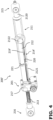
- a tool for adjusting an external fixation strut is globally and schematically indicated with 100, while different embodiments of an external fixation strut are globally and schematically indicated with 200, 200', 200", 200"'.
- the second shaft 213 has an intermediate shank 2130 which is externally threaded.
- the intermediate shank 2130 is rotatably inserted within a sleeve 2160 of the respective end 216 of the strut 200 on one side, and within a slidable end-piece 222 on the other side.
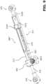
- Figure 4 refers to an alternative embodiment of an external fixation strut 200', which features an improved version of the inductive position sensor 214'.
- the inductive position sensor 214' differs from the previously described position sensor 214 mainly in that the metering cursor 219', the position of which is detected, is kept within the body of the first shaft 212: in particular, within the tubular element defined by the sliding body 2121.
- the internal metering cursor 219' is preferable since it does not interfere with the readings on the external scales, and it greatly reduces the risk of damages from handling.
- the groove may not be a pass-through groove, being only present on the inner wall. Therefore, the groove is not visible from the outside.
- a hole can be added on the sliding body 2121 to allow gluing/welding of the cursor.
- the internal metering cursor 219' further features a lateral protrusion 2191 which extends at least partly through the slit 220 and which exhibits an index 2192 for visual reading of the element's position of on an underlying metered scale.
- the inductive position sensor 214' further comprises a sensing strip 2142, which is obtained as a flexible printed circuit board in a per se known manner.
- Figure 6 shows a cross-section of the external fixation strut 200' which shows further details of the inductive position sensor 214' and of its sensing strip 2142.
- the sensing strip 2142 is attached over an elongated support plate 2143 made of ferromagnetic material, for instance mu-metal.
- the ferrite plate 2143 is meant to shield the sensor from external interferences.
- the top face of the sensing strip 2142 faces the internal metering cursor 219' and the ferrite plate 2143 backs the sensing strip 2142 on the other side.
- the sensing strip 2142 can be glued to the ferrite plate 2143 via a double-sided adhesive strip which is provided on the sensing strip 2142. Then, the combined plate-and-strip are inserted within the sliding body 2121 through the slit 220. As an alternative, the ferromagnetic plate is directly provided as a last layer of the sensing strip.
- the position sensor 214' is preferably an absolute sensor.
- Figure 7 shows a schematic side view of a third embodiment of the external fixation strut 200" according to the invention.
- the third embodiment is identical to the previous ones except for the position sensor 214", which is based on a capacitive technology.
- Figure 8 shows a cross-sectional view of the device of figure 7 .
- the position sensor 214" is glued on an internal surface of the sliding body 2121, and it measures the relative position of the end-piece 222.
- the position sensor 214" detects an absolute position of the end-piece 222 of the second shaft 213, returning a measurement value which can be employed to assess the relative position of the second shaft 213 with respect to the first shaft 212.
- Figure 9 shows a schematic perspective view of the external fixation strut 200" according to the third embodiment of the invention, with no further elements disclosed.
- Figures 10-15 refer to fourth embodiment of an external fixation strut 200"', which is shorter in size with respect to the long external fixation strut 200' according to the first embodiment previously discussed.
- the external fixation strut 200′′′ essentially has the same components and main features of the longer embodiments, which are previously described. Such components and features are therefore indicated in the figures by reference numerals previously used, and they are not described anew in the following paragraphs.
- the main structural difference with respect to the longer version is that here the two attachment points defined by the ball-joints 218 are set closer to each other, thanks to the fact that the ball-joint of the first shaft 212 is not placed at the end 215 thereof, but rather at an opposite end of the hollow main body 2120 of the first shaft 215.
- Figure 16 shows a detail in the construction of the previously introduced position sensor 214.
- a flexible signal line 2141 of the position sensor made in form of a flat cable, connects an electronic board 2140 to the body of the sensor 214, which extends in the vicinity of the sensed end-piece 222.
- the electronic board 2140 is meant for sensor powering and data transmission and is meant to connect to a programmable tool 100 via the connecting system which is described in the following.
- the flexible signal line 2141 has at least one curvature to connect the rotatable adjustment mechanism's housing to the rest of the shaft. Said curvature is designed such that the radius is kept above a threshold value to avoid damaging the signal line during the manufacturing process.
- the same construction of the electronic board 2140 with flexible signal line 2141 is also preferably adopted in the position sensors 214', 214" of the second and third embodiments.
- the casing 111 has a substantially cylindrical shape.
- the shape of the housing 111 may be any shape and size convenient for use.
- the device may further comprise a buzzer or any other audio device.
- the device may also comprise wireless charging means, as well as Near-Field Communication (NFC) means for communication with other electronic devices, as it will be detailed below.
- NFC Near-Field Communication
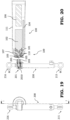
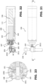
- Figure 19 shows a side view of the programmable tool 100 about to be coupled with an external fixation strut 200.
- Figure 20 is a cross-sectional view of the two devices of figure 19 , and schematically shows the main components inside the casing 111 of the programmable tool 100.
- the programmable tool 100 comprises a power source 106 in the form of a rechargeable battery, an electric motor 102 which preferably comprises a gearbox in-line with a coaxial output shaft 101, and a controller 104, for example in the form of a PCB.
- the controller 104 is adapted to manage the operation of the tool 100 and is not limited by a particular configuration.
- the programmable tool 100 may also comprise an internal memory, which can be conveniently used for storing a patient's prescription and an actual length of a plurality of struts making up an external fixator to be adjusted by the tool 100.
- an internal memory which can be conveniently used for storing a patient's prescription and an actual length of a plurality of struts making up an external fixator to be adjusted by the tool 100.
- the present disclosure is not limited by the architecture of the tool memory, which may be an integral part of the controller 104 or also a separate memory portion which is operatively connected to said controller 104.
- the programmable tool 100 further comprises means (herein referred to as "TX") for communicating data with an external unit, in particular with an external data source, for example in the form of data ports and/or wireless connectivity.
- TX means for communicating data with an external unit, in particular with an external data source, for example in the form of data ports and/or wireless connectivity.
- the programmable tool has a SIM housing (not shown) which is meant to provide internet connectivity to the device, even if any other suitable means may be used for this purpose.
- Such means TX may also comprise Bluetooth connection ports or Wi-Fi connection ports, as well as the above-mentioned NFC means, for example for connecting with a user device or other external devices.
- the controller 104 of the programmable tool 100 is adapted to communicate with an external portal, directly or via a portable electronic device such as a smartphone, to retrieve a surgeon's prescription and update a status comprising at least the length of the several external fixation struts 200, 200', 200", 200′′′ of an external fixator.
- a first connecting portion 105 which is meant to electrically connect with a second connecting portion 205 of the strut 200, 200', 200", 200"'.
- the prescription data DATA relate to the patient's case which the tool 100 is associated with and comprise the information and instructions for performing an adjustment of the external fixation strut 200 of said patient, such as for example a set of dates and/or times in which the adjustment of said external fixation strut 200 is to be applied, as well as the extent of said adjustment, for example in terms of strut length per adjustment step.
- each prescription has an expiry date. If no prescription is downloaded within that date, the prescription become invalid, and no other treatment is allowed
- the surgeon may confirm by pressing one of the push buttons of the tool 100 (e.g., button 1). Therefore, in standard setup operations, the surgeon confirms the successful download of the prescription data DATA, as above discussed.
- the patient may receive said update (for example via a mobile app) and then he/she may confirm the download of the updated prescription and may then confirm its success.
- the controller 104 then causes the tool 100 to enter a waiting state, for example following a further pressure of one of the push buttons, in which it waits for a preliminary coupling with the external fixation strut 200 of the patient, in particular for communicating data therewith via the first connecting portion 105.
- this preliminary coupling is performed by the surgeon (or by any other suitable operator); in particular, after the tool 100 has been connected to the external fixation strut 200 in the preliminary coupling operation, the controller 104 is able to automatically recognize a coupling state of the tool 100 with said external fixation strut 200 and to signal this coupling state.
- the controller 104 communicates with the external fixation strut 200 via the first connecting portion 105 and the second connecting portion 205, in particular it performs a data communication.
- the controller 104 is able to write an ID to the strut memory in order to give a unique identity to a brand new strut, or to re-code a wrong-coded strut.
- the controller 104 is configured to assign a strut ID to the external fixation strut 200 for the identification thereof.
- the tool 100 i.e., the controller 104 thereof enters an idle state (for example following a further pressure of a push button after the coupling is complete) in which it waits for the prescribed time/date when the strut adjustment is to be applied.
- the patient may also check the next adjustment date/time, for example by pressing a push button of the tool 100.
- the tool 100 may generate an alert (which may be a visual and/or acoustic alert) and the patient may press a push button (for example button 1) of said tool 100; the controller 104 is then configured to cause the tool 100 to enter a further waiting state in which it waits for a successive mechanical coupling with the external fixation strut 200 for applying the prescribed adjustment thereto.
- This successive coupling operation involves a mechanical engagement between the tool 100 and the tool 200 and it is usually performed by the patient.
- the controller 104 is configured to wake-up the tool 100 due to an upcoming treatment.
- the wake-up of the tool 100 is performed by using internal RTC.
- the controller 104 when there is an upcoming treatment, is also programmed to estimate the power-budget to finish the entire treatment.
- the controller 104 is configured to automatically apply the prescribed adjustment by driving dedicated means of the tool 100 which act on the rotatable adjustment mechanism 201 of the external fixation strut 200. More in particular, the controller 104 is configured to drive the motor 102 of the tool 100 according to the prescription data DATA, so as to apply the proper adjustment to the strut 200. As it will be discussed in the following, the length of the external fixation strut 200 may be used for controlling the driving means of the tool 100.
- the patient is informed when the tool has successfully adjusted the strut gradual length and, by newly pressing a push button (e.g., button 1), the tool may return again in the idle state.
- a push button e.g., button 1
- a fixation device comprises a plurality of struts, for example six struts. Therefore, after the coupling with one external fixation strut is completed, the controller 104 is configured to check whether other external fixation struts are to be engaged by the tool 100 and, if yes, to cause said tool 100 to enter a waiting state (for example after pressing a push button) in which it waits for the coupling with said another external fixation strut.
- a waiting state for example after pressing a push button
- the tool 100 after the surgeon has performed the preliminary pairing between the tool 100 and the struts 200, the tool 100 knows exactly the identity of each strut 200 of the external fixation device (e.g., which is the correct strut 1, strut 2, etc.). In this way, if the patient engages the wrong strut, the tool 100 is adapted to returning this feedback to the user and therefore generates a warning in the form of an error message, so that the patient knows that he/she's engaging the wrong strut.
- the external fixation device e.g., which is the correct strut 1, strut 2, etc.
- INFO useful information
- the actual length of the external fixation strut 200 is obtained by the controller 104 by reading data from the position sensor 214 of said external fixation strut 200.
- the information INFO (exchanged during the successive coupling performed by the patient) may relate to a measurement indicative of a length of the external fixation strut 200, and, when the tool 100 is coupled with the external fixation strut 200, the controller 104 is configured to retrieve from the position sensor 2014 of said external fixation strut 200 at least said length. This value may then be used in a successive adjustment step for feedback control when driving the tool 100 according to the prescription data DATA.
- the tool 100 is configured to generate an alert when the date and/or time for the prescribed adjustment is reached, so that the patient may promptly couple said tool 100 the strut 200 when needed.
- the user may also postpone the application of the adjustment of the external fixation strut 200, for example by pressing one of the push buttons of the tool 100 when the alert is generated; in an embodiment, by pressing the bush button 1, the tool enters in the waiting state in which it waits to be coupled with the strut, while by pressing button 2 the correction is postponed.
- the controller 104 when the correction is to be applied and the alert is generated, the controller 104 is programmed in such a way that that patient has the following options:
- the controller 104 is configured to detect from the external unit 300 an update of the prescription data DATA and to download, either directly in its memory or indirectly via the user device 310, said update in order to substitute the previously downloaded prescription data with updated prescription data, so that the proper prescription may always be applied.
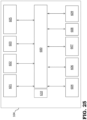
- Figure 25 is a block scheme of an exemplary architecture and connections according to embodiments of the present disclosure, wherein only data connections are shown for the sake of clarity.
- the controller 104 of the tool 100 comprises a mainboard 600 which integrates the proper software modules for accomplishing the functionalities of said tool 100 that have been disclosed above.
- a communication module 601 is configured for establishing a communication protocol with the struts 200.
- the communication between the tool 100 and the struts 200, 200', 200", 200′′′ may occur over a dc-coupled bus where both power and data are carried trough.
- the communication is performed on a half-duplex serial bus where data is written or read to and from the struts 200, 200', 200", 200"'.
- the communication module 601 is also configured to allow the reading of the strut length and position via the strut sensors.
- the controller 104 is also programmed to implement a power management module 602 which is configured to manage all the power paths of the tool 100.
- the controller 104 is also programmed to implement a USB data connection module 603, as well as a motor management/encoder module 604.
- the motor management/encoder module 604 is configured to ensure that the driving of the motor (which may be a brush motor) is done correctly.
- the hardware for driving the motor is apt to detect motor fault/over force, to set the speed, and to verify with a closed loop PID that the target speed is achieved.
- motor acceleration and deceleration ramps are implemented, and the operation is controlled by said closed loop PID by reading as feedback hall sensors.
- the software modules then comprise a keyboard management module 606 configured to recognize the pressure of the pushbuttons of the tool 100 and trigger the proper action.
- the software modules then comprise an external flash and Ram module 607 and a display module 608.
- a connectivity module 609 is configured to enable connection to the external device 300, for example in order to check for new firmware updates, check for new prescriptions, upload on the cloud last life counters, logs or any data that have to be loaded, receive command to enable some specific modes of operation of the tool 100 (e.g., service mode or surgeon mode), and the like.
- a safety module 610 is configured to ensure the proper and safe operation of the tool.
- the prescribed lengthening is monitored both from reading back data from the sensor of the strut and also from the rotation of the motor shaft.
- the right math is applied considering gearbox reduction rates between the motor of the tool 100 and the strut. If the value does not match within a certain threshold, the controller is configured to enter the tool 100 in a safe mode. In other words, the controller is configured to monitor the rotation of the output shaft 101 and to evaluate gearbox reduction rates between the motor 102 of the tool 100 and the strut 200.
- the controller 104 may also be configured to generate interfaces I1-I23 on the display 116 of the tool 100, said interfaces I1-I23 being structured to show a respective operating status of said tool 100.
- Figures 26A-26W show examples of the interfaces displayed in the display of the tool according to embodiments of the present disclosure. These figures will be discussed below in connection with figures 27 and 28 .
- Figures 27 and 28 show a top and a bottom part of a flow diagram of the operation of tool 100 as disclosed above in connection with figure 24 .
- the device can be turned from an off state 500 to an on state 501 by the user, for instance by pressing Button 1 or Button 2 for a given time. This may correspond to passage from interface I1 of figure 26A to interface I2 of figure 26B .
- a similar user action may be demanded to return the device to the off state 500.
- the device After a given time from being turned on, the device will be associated to a specific case 502, as represented by interfaces I3, I4, and I5 of figures 26C, 26D , and 26E .
- the device connects to the internet and retrieves from a dedicated portal the prescription data DATA for the patient's case 503 and, when this prescription treatment has been successfully transferred to the tool memory, informs the patient.
- a dedicated portal the prescription data DATA for the patient's case 503 and, when this prescription treatment has been successfully transferred to the tool memory, informs the patient.
- This is represented by interfaces I6, I7, and I8 of figures 26F, 26G, and 26H .
- the device Upon a user command, for instance the pressure of Button 1, the device enters the coupling waiting state 505 and it will signal through the display 116 that it is ready to connect with a given strut, as shown in interface I10 of figure 26J .
- steps 513-515 are repeated; otherwise, the device signals to the user that the correction is completed 516 (interface I20 of figure 26T ), and returns to the idle state 509.
Landscapes
- Health & Medical Sciences (AREA)
- Orthopedic Medicine & Surgery (AREA)
- Surgery (AREA)
- Life Sciences & Earth Sciences (AREA)
- Engineering & Computer Science (AREA)
- Medical Informatics (AREA)
- Biomedical Technology (AREA)
- Heart & Thoracic Surgery (AREA)
- Nuclear Medicine, Radiotherapy & Molecular Imaging (AREA)
- Molecular Biology (AREA)
- Animal Behavior & Ethology (AREA)
- General Health & Medical Sciences (AREA)
- Public Health (AREA)
- Veterinary Medicine (AREA)
- Mechanical Engineering (AREA)
- Surgical Instruments (AREA)
Claims (4)
- Eine äußere Fixationsstrebe (200, 200', 200", 200"'), umfassend:einen länglichen Körper (211) mit variabler Länge;mindestens einen Sensor (214, 214', 214"), der in den länglichen Körper (211) eingebettet ist und in der Lage ist, mindestens eine Längenänderung des länglichen Körpers (211) zu erfassen;dadurch gekennzeichnet, dass sie ferner mindestens einen kabelgebundenen Datenanschluss umfasst, der mit einem programmierbaren Schraubenschlüssel (100) verbindbar ist, der dazu bestimmt ist, die Länge der äußeren Fixationsstrebe (200, 200', 200", 200‴) automatisch einzustellen, um Daten über die Längenänderung des länglichen Körpers (211) an den programmierbaren Schraubenschlüssel (100) zu übertragen.
- Die äußere Fixationsstrebe (200, 200', 200", 200"') gemäß Anspruch 1, wobei der Sensor (214, 214', 214") ein Positionssensor ist, der eine Position einer ersten Welle (212) relativ zu einer zweiten Welle (213) des länglichen Körpers (211) erfasst, wobei die erste Welle (212) und die zweite Welle (213) teleskopisch miteinander verbunden sind, um den länglichen Körper (211) zu bilden.
- Die äußere Fixationsstrebe (200, 200', 200", 200"') gemäß Anspruch 2, wobei der Sensor (214, 214', 214") entweder ein induktiver oder ein kapazitiver Sensor ist.
- Die äußere Fixationsstrebe (200, 200', 200", 200"') gemäß Anspruch 3, wobei der Sensor (214, 214', 214") die Position eines Messcursors (219, 219') erfasst, der fest entweder mit der ersten Welle (212) oder der zweiten Welle (213) verbunden ist, entlang eines Erfassungsstreifens (2142), der fest mit der jeweils anderen der ersten Welle (212) oder der zweiten Welle (213) verbunden ist.
Priority Applications (5)
| Application Number | Priority Date | Filing Date | Title |
|---|---|---|---|
| EP24217081.9A EP4491331B1 (de) | 2022-12-23 | 2023-01-09 | Schraubenschlüssel zur externen einstellung einer fixierstrebe |
| JP2025528405A JP2026500992A (ja) | 2022-12-23 | 2023-11-16 | 創外固定支柱の調整用レンチ、調整可能な創外固定支柱、ならびに当該固定支柱およびレンチを備えたキット |
| CN202380077664.5A CN120265225A (zh) | 2022-12-23 | 2023-11-16 | 调节外部固定支杆的扳手、可调节外部固定支杆以及包括所述固定支杆和所述扳手的套件 |
| IL320308A IL320308A (en) | 2022-12-23 | 2023-11-16 | Wrench for external fixation strut adjustment, adjustable external fixation strut, and kit comprising said fixator strut and said wrench |
| PCT/EP2023/082038 WO2024132311A1 (en) | 2022-12-23 | 2023-11-16 | Wrench for external fixation strut adjustment, adjustable external fixation strut, and kit comprising said fixator strut and said wrench |
Applications Claiming Priority (1)
| Application Number | Priority Date | Filing Date | Title |
|---|---|---|---|
| US202263477091P | 2022-12-23 | 2022-12-23 |
Related Child Applications (2)
| Application Number | Title | Priority Date | Filing Date |
|---|---|---|---|
| EP24217081.9A Division EP4491331B1 (de) | 2022-12-23 | 2023-01-09 | Schraubenschlüssel zur externen einstellung einer fixierstrebe |
| EP24217081.9A Division-Into EP4491331B1 (de) | 2022-12-23 | 2023-01-09 | Schraubenschlüssel zur externen einstellung einer fixierstrebe |
Publications (2)
| Publication Number | Publication Date |
|---|---|
| EP4389032A1 EP4389032A1 (de) | 2024-06-26 |
| EP4389032B1 true EP4389032B1 (de) | 2025-07-09 |
Family
ID=84888623
Family Applications (1)
| Application Number | Title | Priority Date | Filing Date |
|---|---|---|---|
| EP23150722.9A Active EP4389032B1 (de) | 2022-12-23 | 2023-01-09 | Schraubenschlüssel zur externen fixationsstrebeneinstellung, verstellbare externe fixationsstrebe und kit mit der fixationsstrebe und dem schraubenschlüssel |
Country Status (3)
| Country | Link |
|---|---|
| US (1) | US20240208014A1 (de) |
| EP (1) | EP4389032B1 (de) |
| ES (1) | ES3036674T3 (de) |
Families Citing this family (3)
| Publication number | Priority date | Publication date | Assignee | Title |
|---|---|---|---|---|
| IL300186A (en) * | 2020-07-30 | 2023-03-01 | Synthes Gmbh | Detachable engine |
| ES3038870T3 (en) * | 2022-12-23 | 2025-10-15 | Orthofix Srl | Tool for external fixation strut adjustment |
| EP4389030B1 (de) * | 2022-12-23 | 2025-07-23 | Orthofix S.r.l. | Werkzeug zur externen fixationsstrebeneinstellung, verstellbare externe fixationsstrebe und kit mit der fixationsstrebe und dem werkzeug |
Family Cites Families (9)
| Publication number | Priority date | Publication date | Assignee | Title |
|---|---|---|---|---|
| US4973331A (en) * | 1989-03-08 | 1990-11-27 | Autogenesis Corporation | Automatic compression-distraction-torsion method and apparatus |
| US20020010465A1 (en) * | 2000-01-31 | 2002-01-24 | Ja Kyo Koo | Frame fixator and operation system thereof |
| US8282652B2 (en) * | 2006-08-02 | 2012-10-09 | The Nemours Foundation | Force-controlled autodistraction |
| US8864750B2 (en) | 2008-02-18 | 2014-10-21 | Texas Scottish Rite Hospital For Children | Tool and method for external fixation strut adjustment |
| US9987043B2 (en) * | 2014-10-24 | 2018-06-05 | Stryker European Holdings I, Llc | Methods and systems for adjusting an external fixation frame |
| US10010350B2 (en) * | 2016-06-14 | 2018-07-03 | Stryker European Holdings I, Llc | Gear mechanisms for fixation frame struts |
| WO2018169547A1 (en) * | 2017-03-17 | 2018-09-20 | Spiration, Inc. D.B.A. Olympus Respiratory America | Airway sizing apparatus |
| US11911074B2 (en) * | 2019-01-31 | 2024-02-27 | Smith & Nephew, Inc. | Device for external fixation strut measurement and real-time feedback |
| EP4034009B1 (de) * | 2019-09-26 | 2024-07-10 | Smith & Nephew, Inc. | Automatischer räumlicher rahmen und damit verwendete automatische streben |
-
2023
- 2023-01-09 EP EP23150722.9A patent/EP4389032B1/de active Active
- 2023-01-09 ES ES23150722T patent/ES3036674T3/es active Active
- 2023-12-20 US US18/391,064 patent/US20240208014A1/en active Pending
Also Published As
| Publication number | Publication date |
|---|---|
| ES3036674T3 (en) | 2025-09-23 |
| EP4389032A1 (de) | 2024-06-26 |
| US20240208014A1 (en) | 2024-06-27 |
Similar Documents
| Publication | Publication Date | Title |
|---|---|---|
| EP4389032B1 (de) | Schraubenschlüssel zur externen fixationsstrebeneinstellung, verstellbare externe fixationsstrebe und kit mit der fixationsstrebe und dem schraubenschlüssel | |
| EP2252222B1 (de) | Werkzeug zur einstellung einer externen fixierstrebe | |
| US12471955B2 (en) | Automated spatial frame and automated struts used therewith | |
| US20250134454A1 (en) | User interface for strut device | |
| EP3917419B1 (de) | Vorrichtung zur externen fixierstrebenmessung und echtzeit-feedback | |
| US20240206916A1 (en) | Tool for external fixation strut adjustment, adjustable external fixation strut, and kit comprising said fixator strut and said tool | |
| EP4491331B1 (de) | Schraubenschlüssel zur externen einstellung einer fixierstrebe | |
| US20240206915A1 (en) | Tool for external fixation strut adjustment, adjustable external fixation strut, and kit comprising said fixator strut and said tool | |
| US20240206914A1 (en) | Programmable tool for external fixation strut adjustment | |
| EP4643798A1 (de) | Verbessertes programmierbares werkzeug zur einstellung einer externen fixierstrebe | |
| EP4491332B1 (de) | Werkzeug zur externen fixationsstrebeneinstellung | |
| US20140213936A1 (en) | Devices, systems, and methods for tissue measurement | |
| WO2024132307A1 (en) | Tool for external fixation strut adjustment, adjustable external fixation strut, and kit comprising said fixator strut and said tool | |
| KR101951638B1 (ko) | 관절염 환자를 위한 멀티모듈형 부종 및 압통 측정 장치 | |
| GB2542626A (en) | Surgical aid | |
| EP4353145B1 (de) | Dolorimeteradapter für handgriff-dynamometer | |
| RU211057U1 (ru) | Устройство для мониторинга состояния лётчика вертолёта, применяющего очки ночного видения, в условиях воздействия химического фактора | |
| EP2882472B1 (de) | Instrument zur abscheidung von fettgewebe in einer lipomodellierung | |
| JP2006234451A (ja) | 電子体温計 |
Legal Events
| Date | Code | Title | Description |
|---|---|---|---|
| PUAI | Public reference made under article 153(3) epc to a published international application that has entered the european phase |
Free format text: ORIGINAL CODE: 0009012 |
|
| STAA | Information on the status of an ep patent application or granted ep patent |
Free format text: STATUS: THE APPLICATION HAS BEEN PUBLISHED |
|
| AK | Designated contracting states |
Kind code of ref document: A1 Designated state(s): AL AT BE BG CH CY CZ DE DK EE ES FI FR GB GR HR HU IE IS IT LI LT LU LV MC ME MK MT NL NO PL PT RO RS SE SI SK SM TR |
|
| P01 | Opt-out of the competence of the unified patent court (upc) registered |
Free format text: CASE NUMBER: APP_43936/2024 Effective date: 20240729 |
|
| STAA | Information on the status of an ep patent application or granted ep patent |
Free format text: STATUS: REQUEST FOR EXAMINATION WAS MADE |
|
| 17P | Request for examination filed |
Effective date: 20241203 |
|
| RBV | Designated contracting states (corrected) |
Designated state(s): AL AT BE BG CH CY CZ DE DK EE ES FI FR GB GR HR HU IE IS IT LI LT LU LV MC ME MK MT NL NO PL PT RO RS SE SI SK SM TR |
|
| RIN1 | Information on inventor provided before grant (corrected) |
Inventor name: CHERKASHIN, ALEXANDER Inventor name: SAMCHUKOV, MIKHAIL Inventor name: STANDEFER, KAREN DIVITA Inventor name: ROSS, JOHN DAVID Inventor name: GABURRO, NICOLA Inventor name: FORCOLIN COMINOTTO, ANDREA Inventor name: MISTRETTA, PAOLO Inventor name: DONNICI, MARIO Inventor name: OTTOBONI, ANDREA Inventor name: VENTURINI, DANIELE Inventor name: LORENZINI, DENIS |
|
| GRAP | Despatch of communication of intention to grant a patent |
Free format text: ORIGINAL CODE: EPIDOSNIGR1 |
|
| STAA | Information on the status of an ep patent application or granted ep patent |
Free format text: STATUS: GRANT OF PATENT IS INTENDED |
|
| RIC1 | Information provided on ipc code assigned before grant |
Ipc: A61B 90/00 20160101ALN20250127BHEP Ipc: B25B 21/00 20060101ALI20250127BHEP Ipc: A61B 17/88 20060101ALI20250127BHEP Ipc: A61B 17/66 20060101AFI20250127BHEP |
|
| INTG | Intention to grant announced |
Effective date: 20250205 |
|
| GRAS | Grant fee paid |
Free format text: ORIGINAL CODE: EPIDOSNIGR3 |
|
| GRAA | (expected) grant |
Free format text: ORIGINAL CODE: 0009210 |
|
| STAA | Information on the status of an ep patent application or granted ep patent |
Free format text: STATUS: THE PATENT HAS BEEN GRANTED |
|
| AK | Designated contracting states |
Kind code of ref document: B1 Designated state(s): AL AT BE BG CH CY CZ DE DK EE ES FI FR GB GR HR HU IE IS IT LI LT LU LV MC ME MK MT NL NO PL PT RO RS SE SI SK SM TR |
|
| REG | Reference to a national code |
Ref country code: GB Ref legal event code: FG4D |
|
| REG | Reference to a national code |
Ref country code: CH Ref legal event code: EP |
|
| REG | Reference to a national code |
Ref country code: IE Ref legal event code: FG4D |
|
| REG | Reference to a national code |
Ref country code: DE Ref legal event code: R096 Ref document number: 602023004577 Country of ref document: DE |
|
| REG | Reference to a national code |
Ref country code: ES Ref legal event code: FG2A Ref document number: 3036674 Country of ref document: ES Kind code of ref document: T3 Effective date: 20250923 |
|
| REG | Reference to a national code |
Ref country code: NL Ref legal event code: MP Effective date: 20250709 |
|
| PG25 | Lapsed in a contracting state [announced via postgrant information from national office to epo] |
Ref country code: PT Free format text: LAPSE BECAUSE OF FAILURE TO SUBMIT A TRANSLATION OF THE DESCRIPTION OR TO PAY THE FEE WITHIN THE PRESCRIBED TIME-LIMIT Effective date: 20251110 |
|
| PG25 | Lapsed in a contracting state [announced via postgrant information from national office to epo] |
Ref country code: NL Free format text: LAPSE BECAUSE OF FAILURE TO SUBMIT A TRANSLATION OF THE DESCRIPTION OR TO PAY THE FEE WITHIN THE PRESCRIBED TIME-LIMIT Effective date: 20250709 |
|
| REG | Reference to a national code |
Ref country code: AT Ref legal event code: MK05 Ref document number: 1811076 Country of ref document: AT Kind code of ref document: T Effective date: 20250709 |
|
| PG25 | Lapsed in a contracting state [announced via postgrant information from national office to epo] |
Ref country code: IS Free format text: LAPSE BECAUSE OF FAILURE TO SUBMIT A TRANSLATION OF THE DESCRIPTION OR TO PAY THE FEE WITHIN THE PRESCRIBED TIME-LIMIT Effective date: 20251109 |
|
| PG25 | Lapsed in a contracting state [announced via postgrant information from national office to epo] |
Ref country code: NO Free format text: LAPSE BECAUSE OF FAILURE TO SUBMIT A TRANSLATION OF THE DESCRIPTION OR TO PAY THE FEE WITHIN THE PRESCRIBED TIME-LIMIT Effective date: 20251009 |
|
| REG | Reference to a national code |
Ref country code: LT Ref legal event code: MG9D |
|
| PG25 | Lapsed in a contracting state [announced via postgrant information from national office to epo] |
Ref country code: AT Free format text: LAPSE BECAUSE OF FAILURE TO SUBMIT A TRANSLATION OF THE DESCRIPTION OR TO PAY THE FEE WITHIN THE PRESCRIBED TIME-LIMIT Effective date: 20250709 |
|
| PG25 | Lapsed in a contracting state [announced via postgrant information from national office to epo] |
Ref country code: FI Free format text: LAPSE BECAUSE OF FAILURE TO SUBMIT A TRANSLATION OF THE DESCRIPTION OR TO PAY THE FEE WITHIN THE PRESCRIBED TIME-LIMIT Effective date: 20250709 |
|
| PG25 | Lapsed in a contracting state [announced via postgrant information from national office to epo] |
Ref country code: HR Free format text: LAPSE BECAUSE OF FAILURE TO SUBMIT A TRANSLATION OF THE DESCRIPTION OR TO PAY THE FEE WITHIN THE PRESCRIBED TIME-LIMIT Effective date: 20250709 |
|
| PGFP | Annual fee paid to national office [announced via postgrant information from national office to epo] |
Ref country code: FR Payment date: 20251217 Year of fee payment: 4 |
|
| PG25 | Lapsed in a contracting state [announced via postgrant information from national office to epo] |
Ref country code: GR Free format text: LAPSE BECAUSE OF FAILURE TO SUBMIT A TRANSLATION OF THE DESCRIPTION OR TO PAY THE FEE WITHIN THE PRESCRIBED TIME-LIMIT Effective date: 20251010 |
|
| PG25 | Lapsed in a contracting state [announced via postgrant information from national office to epo] |
Ref country code: SE Free format text: LAPSE BECAUSE OF FAILURE TO SUBMIT A TRANSLATION OF THE DESCRIPTION OR TO PAY THE FEE WITHIN THE PRESCRIBED TIME-LIMIT Effective date: 20250709 |
|
| PG25 | Lapsed in a contracting state [announced via postgrant information from national office to epo] |
Ref country code: LV Free format text: LAPSE BECAUSE OF FAILURE TO SUBMIT A TRANSLATION OF THE DESCRIPTION OR TO PAY THE FEE WITHIN THE PRESCRIBED TIME-LIMIT Effective date: 20250709 |
|
| PG25 | Lapsed in a contracting state [announced via postgrant information from national office to epo] |
Ref country code: PL Free format text: LAPSE BECAUSE OF FAILURE TO SUBMIT A TRANSLATION OF THE DESCRIPTION OR TO PAY THE FEE WITHIN THE PRESCRIBED TIME-LIMIT Effective date: 20250709 Ref country code: BG Free format text: LAPSE BECAUSE OF FAILURE TO SUBMIT A TRANSLATION OF THE DESCRIPTION OR TO PAY THE FEE WITHIN THE PRESCRIBED TIME-LIMIT Effective date: 20250709 |
|
| PG25 | Lapsed in a contracting state [announced via postgrant information from national office to epo] |
Ref country code: RS Free format text: LAPSE BECAUSE OF FAILURE TO SUBMIT A TRANSLATION OF THE DESCRIPTION OR TO PAY THE FEE WITHIN THE PRESCRIBED TIME-LIMIT Effective date: 20251009 |