EP4353145B1 - Dolorimeteradapter für handgriff-dynamometer - Google Patents
Dolorimeteradapter für handgriff-dynamometer Download PDFInfo
- Publication number
- EP4353145B1 EP4353145B1 EP23020472.9A EP23020472A EP4353145B1 EP 4353145 B1 EP4353145 B1 EP 4353145B1 EP 23020472 A EP23020472 A EP 23020472A EP 4353145 B1 EP4353145 B1 EP 4353145B1
- Authority
- EP
- European Patent Office
- Prior art keywords
- sleeve
- adapter according
- bottom cap
- side walls
- adapter
- Prior art date
- Legal status (The legal status is an assumption and is not a legal conclusion. Google has not performed a legal analysis and makes no representation as to the accuracy of the status listed.)
- Active
Links
Images

Classifications
-
- A—HUMAN NECESSITIES
- A61—MEDICAL OR VETERINARY SCIENCE; HYGIENE
- A61B—DIAGNOSIS; SURGERY; IDENTIFICATION
- A61B5/00—Measuring for diagnostic purposes; Identification of persons
- A61B5/0048—Detecting, measuring or recording by applying mechanical forces or stimuli
- A61B5/0053—Detecting, measuring or recording by applying mechanical forces or stimuli by applying pressure, e.g. compression, indentation, palpation, grasping, gauging
-
- A—HUMAN NECESSITIES
- A61—MEDICAL OR VETERINARY SCIENCE; HYGIENE
- A61B—DIAGNOSIS; SURGERY; IDENTIFICATION
- A61B5/00—Measuring for diagnostic purposes; Identification of persons
-
- A—HUMAN NECESSITIES
- A61—MEDICAL OR VETERINARY SCIENCE; HYGIENE
- A61B—DIAGNOSIS; SURGERY; IDENTIFICATION
- A61B10/00—Instruments for taking body samples for diagnostic purposes; Other methods or instruments for diagnosis, e.g. for vaccination diagnosis, sex determination or ovulation-period determination; Throat striking implements
-
- A—HUMAN NECESSITIES
- A61—MEDICAL OR VETERINARY SCIENCE; HYGIENE
- A61B—DIAGNOSIS; SURGERY; IDENTIFICATION
- A61B5/00—Measuring for diagnostic purposes; Identification of persons
- A61B5/16—Devices for psychotechnics; Testing reaction times ; Devices for evaluating the psychological state
-
- A—HUMAN NECESSITIES
- A61—MEDICAL OR VETERINARY SCIENCE; HYGIENE
- A61B—DIAGNOSIS; SURGERY; IDENTIFICATION
- A61B5/00—Measuring for diagnostic purposes; Identification of persons
- A61B5/22—Ergometry; Measuring muscular strength or the force of a muscular blow
- A61B5/224—Measuring muscular strength
-
- A—HUMAN NECESSITIES
- A61—MEDICAL OR VETERINARY SCIENCE; HYGIENE
- A61B—DIAGNOSIS; SURGERY; IDENTIFICATION
- A61B5/00—Measuring for diagnostic purposes; Identification of persons
- A61B5/48—Other medical applications
- A61B5/4824—Touch or pain perception evaluation
Definitions
- the subject of the invention is dolorimetric adapter to hand grip dynamometer designed for pain objectification of patients during a palpation.
- dolorimeters that is medical devices for measuring the intensity of pain during pressure, have been known from the industry. Such devices consist of a movable part, which is used to apply pressure to certain points on the body, and a meter connected to it, allowing to determine the strength of the pressure released.
- a dolorimetric device is known from US5012817A which contains an element with a property which changes depending on the pressure exerted on it.
- a device is provided for attaching the segment to the user's hand so that the segment fits under the user's finger.
- the segment is sized to fit between the finger and the object touched by the user, while allowing essential tactile communication with the finger.
- a device for quantifying the variance of said property from said element is provided.
- a system for measuring sensitivity is known from WO2019204899A1 to be used in patient's diagnostics and treatment, which includes: a handheld, formable device that contains a pressure sensor, a Bluetooth ® radio and a battery, the pressure sensor and Bluetooth radio in electrical communication with the battery, the pressure sensor in electrical communication with the Bluetooth radio; a computer device, a computer device that contains a Bluetooth ® receiver that is in radio communication with the Bluetooth radio, a processor and memory, the memory containing instructions for calibrating the system for a specific patient for calibration, the memory storing a set of calibration and sensitivity data for a specific patient; and a user interface that communicates electronically with the computer device.
- a computer operated sensory testing system is known from EP2482716A2 , which can be used for further studies on pain and supporting clinical diagnosis and treatment of pain syndromes.
- the system includes actuators to deliver pressure/strain (tension), auditory, olfactory and other stimuli to the patient.
- the system includes software to control the delivery of the stimuli.
- the system is further capable of receiving feedback on the stimuli received.
- the purpose of the invention is to develop such a dolorimetric adapter that, when used together with a hand grip dynamometer, will allow an objective study of pain sensation in both inpatient and outpatient settings.
- the ease of use of the indicated invention will make it possible to accurately determine points of maximum soreness before conducting therapy and to compare the results after therapeutic intervention. Obtaining accurate, objective measurements significantly improves the quality of the treatment performed.
- the invention allows for increased testing capability with a single device, in this case a hand grip dynamometer, without the need to purchase and calibrate further measuring devices.
- a hand grip dynamometer for testing gives the possibility of acting with greater force, up to 120 kg.
- the body of the adapter is placed on the handle of the dynamometer, after which a cap is placed in its upper part to lock the body. Inside the cap, there is a pressure plate, which is further tightened using a thumb screw. A pressure pin is screwed into the lower part of the body, along with a cap that directly exerts pressure on the patient's body. Making the overlays in two sizes allows testing with a similar pressure area for the index finger (16mm diameter) and for the thumb (20mm diameter).
- the solution is an additional device, dedicated for use with a hand grip dynamometer.
- the indicated solution allows to increase the possibility of testing with one device, without the need to purchase and calibrate further measuring devices.
- the use of a hand grip dynamometer for testing gives the possibility of acting with a much greater force, up to 120 kg, compared to commercially available dolorimeters.
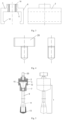
- fig. 1 shows the pressure pin
- fig. 2 the bottom cap fig. 3 the sleeve fig. 4 the screw fig. 5 the dolorimetric adapter
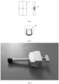
- fig. 6 the pressure plate
- fig. 7 a blind hole in the bottom cap
- fig. 8 the dolorimetric adapter with hand grip dynamometer.
- Example I The dolorimetric adapter for the hand grip dynamometer consists of a body 1 embedded in a sleeve 2.
- Sleeve 2 has the shape of a channel, with side walls 6.
- the side walls 6 have the same dimension and are parallel to each other.
- Sleeve 2 has a base 3 and two side walls 6, set to the base 3 at right angles.
- the side walls 6 are L-shaped and their block serifs 12 face each other.
- Sleeve 2 has a through-hole 10 for a screw 20 preferably wing-head thumb screw, pressing the sleeve 2 against the body 1 through the pressure plate 4.
- the pressure plate 4 has a blind seating hole 16, placed in one axis with the through-hole 10.
- the body 1 consists of a channel-shaped bottom cap 7 and a pressure pin 8.
- a blind hole 19 In the upper wall 9 of the bottom cap 7, there is a blind hole 19 in which the pressure pin 8 seated through a threaded connection 18 is embedded.
- the pressure pin 8 is cylindrical in shape, and has an expansion 11 in the upper part, on which the locking cap 13 is seated.
- the bottom cap 7 has side walls 14.
- the side walls 14 have the same dimensions and are parallel to each other.
- the side walls 14 have block serifs 15 facing in opposite directions to each other.
- Block serifs 15 of the bottom cap 7 are adjusted in length and width to the internal dimensions of block serifs 12 of the sleeve 2.
- the top wall 9 of the bottom cap 7 has two symmetrical bevels relative to the vertical axis of the bottom cap 7.
- Dolorymetric adapter to hand grip dynamometer is characterized in that it consists of a body 1 embedded in sleeve 2 on pressure plate 4.
- the channel-shaped sleeve 2 has mutually parallel side walls 6 and a base 3 embedded at a right angle, which side walls 6 are L-shaped and have their block serifs 12 facing each other, and the sleeve 2 having a through hole 10 with a screw 20.
- the body 1 consists of a channel-shaped bottom cap 7 and pressure pin 8, with the upper wall 9 of bottom cap 7 having a blind hole 19 in which a cylindrical pressure pin 8 with an expansion 11 in the upper part is embedded.
- the bottom cap 7 has mutually parallel side walls 14 with block serifs 15 facing in opposite directions.
- Example III is different from I due to having a cuboid-shaped pressure plate 4 with dimensions not greater than the width and length of the upper wall 5 base 3 of sleeve 2 embedded on the bottom base 3 of sleeve 2.
Landscapes
- Health & Medical Sciences (AREA)
- Life Sciences & Earth Sciences (AREA)
- Engineering & Computer Science (AREA)
- Veterinary Medicine (AREA)
- General Health & Medical Sciences (AREA)
- Heart & Thoracic Surgery (AREA)
- Medical Informatics (AREA)
- Molecular Biology (AREA)
- Surgery (AREA)
- Animal Behavior & Ethology (AREA)
- Biomedical Technology (AREA)
- Public Health (AREA)
- Pathology (AREA)
- Biophysics (AREA)
- Physics & Mathematics (AREA)
- Psychiatry (AREA)
- Hospice & Palliative Care (AREA)
- Developmental Disabilities (AREA)
- Psychology (AREA)
- Social Psychology (AREA)
- Educational Technology (AREA)
- Child & Adolescent Psychology (AREA)
- Pain & Pain Management (AREA)
- Physical Education & Sports Medicine (AREA)
- Finger-Pressure Massage (AREA)
- Measuring Fluid Pressure (AREA)
Claims (10)
- Dolorimeteradapter für Handgriff-dynamometer ist dadurch gekennzeichnet, dass er aus einem Körper (1) besteht, der in einer Kappe (2) in Form eines Kanals auf der Druckplatte (4) montiert ist, wobei die Kappe (2) die Form eines Kanals hat und parallele Seitenwände (6) sowie eine Basis (3) aufweist, die im rechten Winkel angebracht ist, die Seitenwände (6) haben eine L-Form und sind mit Balken-Serifs (12) zueinander gerichtet, zudem besitzt die Kappe (2) eine Durchgangsbohrung (10) mit einer Schraube (20), auf deren auf unterer Basis (3) der Kappe (2) die Druckplatte (4) montiert ist, und der Körper (1) besteht aus einer Bodenkappe (7) in Form eines Kanals und einer Druckspindel(8), wo sich in der oberen Wand (9) der Bodenkappe (7) eine Sacklochbohrung (19) befindet, in der die zylindrische Druckspindel (8) mit einer Verlängerung (11) im oberen Teil eingesetzt ist, und die Bodenkappe (7) hat parallele Seitenwände (14) mit Balken-Serifs (15), die in entgegengesetzte Richtungen weisen.
- Adapter nach Anspruch 1, dadurch gekennzeichnet, dass die Seitenwände (6) die gleichen Abmessungen aufweisen.
- Adapter nach Anspruch 1 oder 2, dadurch gekennzeichnet, dass die Druckplatte (4) die Form eines Quaders hat und vorzugsweise in ihren Abmessungen an die obere Fläche (5) der Basis (3) der Kappe (2) angepasst ist oder Abmessungen aufweist, die nicht größer sind als die Breite und Länge der oberen Fläche (5) der Basis (3) der Kappe (2).
- Adapter nach Anspruch 1, 2 oder 3, dadurch gekennzeichnet, dass die Schraube (20) eine Flügelschraube ist.
- Adapter nach Anspruch 1, 2, 3 oder 4, dadurch gekennzeichnet, dass die Druckspindel (8) im unteren Bereich ein Gewinde (18) aufweist.
- Adapter nach Anspruch 1, 2, 3, 4 oder 5, dadurch gekennzeichnet, dass die Druckspindel (8) im oberen Bereich eine Schutzkappe (13) besitzt.
- Adapter nach Anspruch 1, 2, 3, 4, 5 oder 6, dadurch gekennzeichnet, dass die Seitenwände (14) die gleichen Abmessungen aufweisen.
- Adapter nach Anspruch 1, 2, 3, 4, 5, 6 oder 7, dadurch gekennzeichnet, dass die Balken-Serifs (15) der Bodenkappe (7) in Länge und Breite an die Innenmaße der Balken-Serifs (12) der Kappe (2) angepasst sind.
- Adapter nach Anspruch 1, 2, 3, 4, 5, 6, 7 oder 8, dadurch gekennzeichnet, dass die obere Wand (9) der Bodenkappe (7) zwei symmetrische Abschrägungen (17) bezüglich der vertikalen Achse der Bodenkappe (7) aufweist.
- Adapter nach Anspruch 1, 2, 3, 4, 5, 6, 7, 8 oder 9, dadurch gekennzeichnet, dass die Druckplatte (4) eine Sackbohrung (16) aufweist, die mit der Durchgangsbohrung (10) fluchtet.
Applications Claiming Priority (1)
| Application Number | Priority Date | Filing Date | Title |
|---|---|---|---|
| PL442529A PL442529A1 (pl) | 2022-10-14 | 2022-10-14 | Adapter dolorymetryczny do dynamometru dłoniowego |
Publications (3)
| Publication Number | Publication Date |
|---|---|
| EP4353145A1 EP4353145A1 (de) | 2024-04-17 |
| EP4353145C0 EP4353145C0 (de) | 2025-04-09 |
| EP4353145B1 true EP4353145B1 (de) | 2025-04-09 |
Family
ID=86325394
Family Applications (1)
| Application Number | Title | Priority Date | Filing Date |
|---|---|---|---|
| EP23020472.9A Active EP4353145B1 (de) | 2022-10-14 | 2023-10-13 | Dolorimeteradapter für handgriff-dynamometer |
Country Status (2)
| Country | Link |
|---|---|
| EP (1) | EP4353145B1 (de) |
| PL (2) | PL442529A1 (de) |
Family Cites Families (8)
| Publication number | Priority date | Publication date | Assignee | Title |
|---|---|---|---|---|
| US3672219A (en) * | 1970-11-12 | 1972-06-27 | Us Air Force | Adjustable hydraulic/electric hand grip dynamometer |
| US5012817A (en) | 1989-05-19 | 1991-05-07 | University Of Victoria | Dolorimeter apparatus |
| JP4875916B2 (ja) * | 2006-03-30 | 2012-02-15 | アニマ株式会社 | 筋力測定装置 |
| WO2011041683A2 (en) | 2009-10-02 | 2011-04-07 | The Regents Of The University Of Michigan | Multimodal automated sensory testing system |
| JP2011120727A (ja) * | 2009-12-10 | 2011-06-23 | Ito Chotanpa Kk | 生体データ測定器及び生体データ測定システム、並びに、筋力計及び筋力測定システム |
| KR102239670B1 (ko) * | 2015-12-28 | 2021-04-13 | 가부시키가이샤 오하시 치소오 겐큐쇼 | 악력 검출 기구, 악력 검출 기구를 구비하는 운동구 및 그 운동구의 사용 방법 |
| CA3003155A1 (en) | 2018-04-25 | 2019-10-25 | Dynamic Disc Designs Corp. | Sensitivity metering system for use in patient diagnosis |
| KR102261453B1 (ko) * | 2019-05-13 | 2021-06-07 | (주)아이쿱 | 통증 모니터링 장치 및 방법 |
-
2022
- 2022-10-14 PL PL442529A patent/PL442529A1/pl unknown
-
2023
- 2023-10-13 PL PL23020472.9T patent/PL4353145T3/pl unknown
- 2023-10-13 EP EP23020472.9A patent/EP4353145B1/de active Active
Also Published As
| Publication number | Publication date |
|---|---|
| PL4353145T3 (pl) | 2025-07-28 |
| EP4353145A1 (de) | 2024-04-17 |
| EP4353145C0 (de) | 2025-04-09 |
| PL442529A1 (pl) | 2023-05-15 |
Similar Documents
| Publication | Publication Date | Title |
|---|---|---|
| US8485075B1 (en) | Electronic torque wrench | |
| US9307906B2 (en) | Multimodal automated sensory testing system | |
| US6792801B2 (en) | Device for measuring force and angles | |
| JP6158294B2 (ja) | 手掌の握る力を測定するシステム | |
| WO2018085532A3 (en) | Surgical depth instrument having neuromonitoring capabilities | |
| Rinderknecht et al. | Reliable and rapid robotic assessment of wrist proprioception using a gauge position matching paradigm | |
| CN102438506A (zh) | 用于评估温痛和振动敏感性的设备和方法 | |
| US3670573A (en) | Apparatus for measuring thumb and finger force | |
| CN203259305U (zh) | 触头压力测量仪的定标设备 | |
| EP4353145B1 (de) | Dolorimeteradapter für handgriff-dynamometer | |
| KR101771156B1 (ko) | 스킨 폴드 캘리퍼 | |
| US20160256103A1 (en) | Wearable medical examination and treatment device and wearable medical examination and treatment system comprising the same | |
| Evans et al. | Controlled manual loading of body tissues: towards the next generation of pressure algometer | |
| KR20150095439A (ko) | 생체 정보 측정 시스템 및 그 측정 방법 | |
| US10893827B2 (en) | Device for measuring muscle relaxation and monitoring equipment | |
| US8376909B1 (en) | Therapy evaluation machine for measuring range of motion of a wrist, a hand and fingers | |
| EP4104753A1 (de) | Vorrichtung zum messen der empfindlichkeit eines probanden | |
| KR20210129899A (ko) | 휴대용 통증 측정 장치 | |
| EP4182910B1 (de) | Zahntrainingsvorrichtungen, -systeme und -verfahren | |
| KR20200041081A (ko) | 도수치료용 압력 피드백 기기 | |
| RU2093108C1 (ru) | Устройство для определения центрального соотношения челюстей | |
| Bedenik et al. | Forceps Pressure Algometer Based on Load Cell | |
| US20160183837A1 (en) | Detection of tissue injury using microcurrent. Device name - Zone Finder | |
| AU2024302009A1 (en) | Frailty assessment device and system | |
| CN120265225A (zh) | 调节外部固定支杆的扳手、可调节外部固定支杆以及包括所述固定支杆和所述扳手的套件 |
Legal Events
| Date | Code | Title | Description |
|---|---|---|---|
| PUAI | Public reference made under article 153(3) epc to a published international application that has entered the european phase |
Free format text: ORIGINAL CODE: 0009012 |
|
| STAA | Information on the status of an ep patent application or granted ep patent |
Free format text: STATUS: THE APPLICATION HAS BEEN PUBLISHED |
|
| AK | Designated contracting states |
Kind code of ref document: A1 Designated state(s): AL AT BE BG CH CY CZ DE DK EE ES FI FR GB GR HR HU IE IS IT LI LT LU LV MC ME MK MT NL NO PL PT RO RS SE SI SK SM TR |
|
| STAA | Information on the status of an ep patent application or granted ep patent |
Free format text: STATUS: REQUEST FOR EXAMINATION WAS MADE |
|
| 17P | Request for examination filed |
Effective date: 20240628 |
|
| RBV | Designated contracting states (corrected) |
Designated state(s): AL AT BE BG CH CY CZ DE DK EE ES FI FR GB GR HR HU IE IS IT LI LT LU LV MC ME MK MT NL NO PL PT RO RS SE SI SK SM TR |
|
| GRAP | Despatch of communication of intention to grant a patent |
Free format text: ORIGINAL CODE: EPIDOSNIGR1 |
|
| STAA | Information on the status of an ep patent application or granted ep patent |
Free format text: STATUS: GRANT OF PATENT IS INTENDED |
|
| INTG | Intention to grant announced |
Effective date: 20241105 |
|
| GRAS | Grant fee paid |
Free format text: ORIGINAL CODE: EPIDOSNIGR3 |
|
| GRAA | (expected) grant |
Free format text: ORIGINAL CODE: 0009210 |
|
| STAA | Information on the status of an ep patent application or granted ep patent |
Free format text: STATUS: THE PATENT HAS BEEN GRANTED |
|
| AK | Designated contracting states |
Kind code of ref document: B1 Designated state(s): AL AT BE BG CH CY CZ DE DK EE ES FI FR GB GR HR HU IE IS IT LI LT LU LV MC ME MK MT NL NO PL PT RO RS SE SI SK SM TR |
|
| REG | Reference to a national code |
Ref country code: GB Ref legal event code: FG4D |
|
| REG | Reference to a national code |
Ref country code: CH Ref legal event code: EP |
|
| REG | Reference to a national code |
Ref country code: IE Ref legal event code: FG4D |
|
| U01 | Request for unitary effect filed |
Effective date: 20250414 |
|
| U07 | Unitary effect registered |
Designated state(s): AT BE BG DE DK EE FI FR IT LT LU LV MT NL PT RO SE SI Effective date: 20250422 |
|
| PG25 | Lapsed in a contracting state [announced via postgrant information from national office to epo] |
Ref country code: ES Free format text: LAPSE BECAUSE OF FAILURE TO SUBMIT A TRANSLATION OF THE DESCRIPTION OR TO PAY THE FEE WITHIN THE PRESCRIBED TIME-LIMIT Effective date: 20250409 |
|
| PG25 | Lapsed in a contracting state [announced via postgrant information from national office to epo] |
Ref country code: NO Free format text: LAPSE BECAUSE OF FAILURE TO SUBMIT A TRANSLATION OF THE DESCRIPTION OR TO PAY THE FEE WITHIN THE PRESCRIBED TIME-LIMIT Effective date: 20250709 Ref country code: GR Free format text: LAPSE BECAUSE OF FAILURE TO SUBMIT A TRANSLATION OF THE DESCRIPTION OR TO PAY THE FEE WITHIN THE PRESCRIBED TIME-LIMIT Effective date: 20250710 |
|
| PG25 | Lapsed in a contracting state [announced via postgrant information from national office to epo] |
Ref country code: HR Free format text: LAPSE BECAUSE OF FAILURE TO SUBMIT A TRANSLATION OF THE DESCRIPTION OR TO PAY THE FEE WITHIN THE PRESCRIBED TIME-LIMIT Effective date: 20250409 |
|
| PG25 | Lapsed in a contracting state [announced via postgrant information from national office to epo] |
Ref country code: RS Free format text: LAPSE BECAUSE OF FAILURE TO SUBMIT A TRANSLATION OF THE DESCRIPTION OR TO PAY THE FEE WITHIN THE PRESCRIBED TIME-LIMIT Effective date: 20250709 |
|
| PG25 | Lapsed in a contracting state [announced via postgrant information from national office to epo] |
Ref country code: IS Free format text: LAPSE BECAUSE OF FAILURE TO SUBMIT A TRANSLATION OF THE DESCRIPTION OR TO PAY THE FEE WITHIN THE PRESCRIBED TIME-LIMIT Effective date: 20250809 |
|
| U20 | Renewal fee for the european patent with unitary effect paid |
Year of fee payment: 3 Effective date: 20251009 |
|
| PG25 | Lapsed in a contracting state [announced via postgrant information from national office to epo] |
Ref country code: SM Free format text: LAPSE BECAUSE OF FAILURE TO SUBMIT A TRANSLATION OF THE DESCRIPTION OR TO PAY THE FEE WITHIN THE PRESCRIBED TIME-LIMIT Effective date: 20250409 |
|
| PG25 | Lapsed in a contracting state [announced via postgrant information from national office to epo] |
Ref country code: CZ Free format text: LAPSE BECAUSE OF FAILURE TO SUBMIT A TRANSLATION OF THE DESCRIPTION OR TO PAY THE FEE WITHIN THE PRESCRIBED TIME-LIMIT Effective date: 20250409 |
|
| PGFP | Annual fee paid to national office [announced via postgrant information from national office to epo] |
Ref country code: PL Payment date: 20251009 Year of fee payment: 3 |
|
| PG25 | Lapsed in a contracting state [announced via postgrant information from national office to epo] |
Ref country code: SK Free format text: LAPSE BECAUSE OF FAILURE TO SUBMIT A TRANSLATION OF THE DESCRIPTION OR TO PAY THE FEE WITHIN THE PRESCRIBED TIME-LIMIT Effective date: 20250409 |
|
| PLBE | No opposition filed within time limit |
Free format text: ORIGINAL CODE: 0009261 |
|
| STAA | Information on the status of an ep patent application or granted ep patent |
Free format text: STATUS: NO OPPOSITION FILED WITHIN TIME LIMIT |
|
| REG | Reference to a national code |
Ref country code: CH Ref legal event code: L10 Free format text: ST27 STATUS EVENT CODE: U-0-0-L10-L00 (AS PROVIDED BY THE NATIONAL OFFICE) Effective date: 20260218 |
|
| 26N | No opposition filed |
Effective date: 20260112 |