EP4388959B1 - Autonomer reinigungsroboter mit abfalldeflektoren - Google Patents
Autonomer reinigungsroboter mit abfalldeflektoren Download PDFInfo
- Publication number
- EP4388959B1 EP4388959B1 EP23216591.0A EP23216591A EP4388959B1 EP 4388959 B1 EP4388959 B1 EP 4388959B1 EP 23216591 A EP23216591 A EP 23216591A EP 4388959 B1 EP4388959 B1 EP 4388959B1
- Authority
- EP
- European Patent Office
- Prior art keywords
- cleaning robot
- autonomous cleaning
- connecting channel
- deflector
- deflection surface
- Prior art date
- Legal status (The legal status is an assumption and is not a legal conclusion. Google has not performed a legal analysis and makes no representation as to the accuracy of the status listed.)
- Active
Links
Images

Classifications
-
- A—HUMAN NECESSITIES
- A47—FURNITURE; DOMESTIC ARTICLES OR APPLIANCES; COFFEE MILLS; SPICE MILLS; SUCTION CLEANERS IN GENERAL
- A47L—DOMESTIC WASHING OR CLEANING; SUCTION CLEANERS IN GENERAL
- A47L11/00—Machines for cleaning floors, carpets, furniture, walls, or wall coverings
- A47L11/40—Parts or details of machines not provided for in groups A47L11/02 - A47L11/38, or not restricted to one of these groups, e.g. handles, arrangements of switches, skirts, buffers, levers
- A47L11/4036—Parts or details of the surface treating tools
- A47L11/4044—Vacuuming or pick-up tools; Squeegees
-
- A—HUMAN NECESSITIES
- A47—FURNITURE; DOMESTIC ARTICLES OR APPLIANCES; COFFEE MILLS; SPICE MILLS; SUCTION CLEANERS IN GENERAL
- A47L—DOMESTIC WASHING OR CLEANING; SUCTION CLEANERS IN GENERAL
- A47L11/00—Machines for cleaning floors, carpets, furniture, walls, or wall coverings
- A47L11/02—Floor surfacing or polishing machines
- A47L11/10—Floor surfacing or polishing machines motor-driven
- A47L11/12—Floor surfacing or polishing machines motor-driven with reciprocating or oscillating tools
-
- A—HUMAN NECESSITIES
- A47—FURNITURE; DOMESTIC ARTICLES OR APPLIANCES; COFFEE MILLS; SPICE MILLS; SUCTION CLEANERS IN GENERAL
- A47L—DOMESTIC WASHING OR CLEANING; SUCTION CLEANERS IN GENERAL
- A47L11/00—Machines for cleaning floors, carpets, furniture, walls, or wall coverings
- A47L11/24—Floor-sweeping machines, motor-driven
-
- A—HUMAN NECESSITIES
- A47—FURNITURE; DOMESTIC ARTICLES OR APPLIANCES; COFFEE MILLS; SPICE MILLS; SUCTION CLEANERS IN GENERAL
- A47L—DOMESTIC WASHING OR CLEANING; SUCTION CLEANERS IN GENERAL
- A47L11/00—Machines for cleaning floors, carpets, furniture, walls, or wall coverings
- A47L11/40—Parts or details of machines not provided for in groups A47L11/02 - A47L11/38, or not restricted to one of these groups, e.g. handles, arrangements of switches, skirts, buffers, levers
- A47L11/4013—Contaminants collecting devices, i.e. hoppers, tanks or the like
-
- A—HUMAN NECESSITIES
- A47—FURNITURE; DOMESTIC ARTICLES OR APPLIANCES; COFFEE MILLS; SPICE MILLS; SUCTION CLEANERS IN GENERAL
- A47L—DOMESTIC WASHING OR CLEANING; SUCTION CLEANERS IN GENERAL
- A47L11/00—Machines for cleaning floors, carpets, furniture, walls, or wall coverings
- A47L11/40—Parts or details of machines not provided for in groups A47L11/02 - A47L11/38, or not restricted to one of these groups, e.g. handles, arrangements of switches, skirts, buffers, levers
- A47L11/4036—Parts or details of the surface treating tools
- A47L11/4041—Roll shaped surface treating tools
-
- A—HUMAN NECESSITIES
- A47—FURNITURE; DOMESTIC ARTICLES OR APPLIANCES; COFFEE MILLS; SPICE MILLS; SUCTION CLEANERS IN GENERAL
- A47L—DOMESTIC WASHING OR CLEANING; SUCTION CLEANERS IN GENERAL
- A47L11/00—Machines for cleaning floors, carpets, furniture, walls, or wall coverings
- A47L11/40—Parts or details of machines not provided for in groups A47L11/02 - A47L11/38, or not restricted to one of these groups, e.g. handles, arrangements of switches, skirts, buffers, levers
- A47L11/4072—Arrangement of castors or wheels
-
- A—HUMAN NECESSITIES
- A47—FURNITURE; DOMESTIC ARTICLES OR APPLIANCES; COFFEE MILLS; SPICE MILLS; SUCTION CLEANERS IN GENERAL
- A47L—DOMESTIC WASHING OR CLEANING; SUCTION CLEANERS IN GENERAL
- A47L11/00—Machines for cleaning floors, carpets, furniture, walls, or wall coverings
- A47L11/40—Parts or details of machines not provided for in groups A47L11/02 - A47L11/38, or not restricted to one of these groups, e.g. handles, arrangements of switches, skirts, buffers, levers
- A47L11/4094—Accessories to be used in combination with conventional vacuum-cleaning devices
-
- A—HUMAN NECESSITIES
- A47—FURNITURE; DOMESTIC ARTICLES OR APPLIANCES; COFFEE MILLS; SPICE MILLS; SUCTION CLEANERS IN GENERAL
- A47L—DOMESTIC WASHING OR CLEANING; SUCTION CLEANERS IN GENERAL
- A47L2201/00—Robotic cleaning machines, i.e. with automatic control of the travelling movement or the cleaning operation
Definitions
- the present invention relates to the field of robot vacuum cleaners capable of moving autonomously over a surface to be cleaned and making it possible to vacuum up dust and waste present on the surface to be cleaned, which may for example be tiles, parquet, laminate, carpet or a rug, and possibly to wash the surface to be cleaned simultaneously with a vacuuming operation.
- the present invention aims to remedy these drawbacks.
- the technical problem underlying the invention consists in particular in providing an autonomous cleaning robot which is of simple, economical and compact structure, while having high cleaning performance.
- the suction chamber comprises a waste deflector comprising a first deflector portion and a second deflector portion located on either side of the inlet opening of the connecting channel, the first and second deflector portions respectively comprising a first deflection surface and a second deflection surface which are configured to be oriented towards the surface to be cleaned and which extend transversely, and for example substantially perpendicularly, to a main direction of movement of the autonomous cleaning robot, the first deflection surface being inclined such that the distance between the surface to be cleaned and the first deflection surface increases in the direction of the inlet opening of the connecting channel, and for example from a first end of the rotating cleaning brush towards the inlet opening of the connecting channel, the second deflection surface being inclined such that the distance between the surface to be cleaned and the second deflection surface increases in the direction of the inlet opening of the connecting channel, and for example from a second end of the rotating cleaning brush towards the inlet opening of the connecting channel.
- Such a configuration of the waste deflector allows for efficient guidance waste, having entered the suction chamber in particular from lateral portions of the suction chamber, towards the inlet opening of the connecting channel (via successive rebounds of the waste against in particular on the first and second deflection surfaces), where the waste is then sucked up and guided towards the waste collection container.
- Such a configuration of the waste deflector thus ensures efficient collection of the waste present on the surface to be cleaned, without the need to use a suction unit with high power, and therefore while preserving the autonomy of the autonomous cleaning robot.
- the autonomous cleaning robot of the present invention is designed, like the majority of autonomous cleaning robots, to efficiently clean floors when it moves in a direction of movement parallel to the longitudinal axis of the autonomous cleaning robot and in a predetermined direction of movement.
- the direction of movement parallel to the longitudinal axis of the autonomous cleaning robot and the predetermined direction of movement define a main direction of movement of the autonomous cleaning robot of the present invention.
- a front part or a rear part of the main body of the autonomous cleaning robot is identified relative to the main direction of movement of the autonomous cleaning robot.
- the autonomous cleaning robot may further have one or more of the following features, taken alone or in combination.
- the waste deflector is configured to prevent rotation of the waste within the suction chamber.
- the first deflection surface extends from a first lateral edge of the suction mouth to the inlet opening of the connecting channel
- the second deflection surface extends from a second lateral edge of the suction mouth to the inlet opening of the connecting channel.
- each of the first and second deflection surfaces is configured to be inclined relative to the horizontal by an angle of inclination of between 2° and 20°, advantageously between 2° and 10°, and for example approximately 5°, when the autonomous cleaning robot rests on a horizontal surface.
- an angle of inclination of between 2° and 20°, advantageously between 2° and 10°, and for example approximately 5°, when the autonomous cleaning robot rests on a horizontal surface.
- each of the first and second deflection surfaces has a width, measured parallel to the main direction of movement of the autonomous cleaning robot, which increases towards the inlet opening of the connecting channel.
- each of the first and second deflection surfaces is substantially planar.
- the autonomous cleaning robot further comprises a lower deflector located at the rear of the brush rotation axis and extending at least partly opposite the inlet opening of the connecting channel, the lower deflector comprising a lower deflection surface which partly delimits the suction chamber and which is configured to deflect, upwards and towards the connecting channel, waste projected backwards by the rotating cleaning brush onto the lower deflection surface.
- each of the first and second deflection surfaces is located opposite the lower deflector, and for example the lower deflection surface.
- waste entering the suction chamber from a lateral portion of the suction chamber, bounces successively on the lower deflector and one of the first and second deflection surfaces and is gradually conveyed to the inlet opening of the connecting channel, where it is then sucked and guided towards the waste collection container.
- the waste deflector further increases the cleaning performance of the autonomous cleaning robot according to the present invention.
- the lower deflector is elongated and extends substantially parallel to the axis of rotation of the brush.
- the lower deflector extends over substantially the entire length of the rotating cleaning brush. Such a configuration of the lower deflector limits the risks of expulsion of large waste from the suction chamber, and therefore promotes the suction of this waste through the connecting channel.
- the lower deflector forms a rear edge of the suction mouth.
- Such a configuration of the lower deflector makes it possible to limit the depth of the autonomous cleaning robot according to the present invention, while promoting the guidance of the vacuumed waste towards the connecting channel.
- the lower deflection surface is inclined backwards and upwards and is configured to be inclined relative to the horizontal by an angle of inclination of between 20 and 55°, advantageously between 25 and 45°, and is for example approximately 37°, when the autonomous cleaning robot rests on a horizontal surface.
- Such an inclination of the lower deflection surface further promotes the guidance of the vacuumed waste towards the waste collection container, while limiting the height and depth requirements of the autonomous cleaning robot according to the present invention.
- the lower deflection surface is flat.
- the autonomous cleaning robot further comprises an upper deflector extending at least partly opposite an outlet opening of the connecting channel, the upper deflector comprising an upper deflection surface which is configured to deflect, rearwardly and towards the waste collection container, waste exiting, upwardly, from the connecting channel.
- Such a configuration of the lower and upper deflectors and the connecting channel makes it possible to effectively guide the waste, projected by the rotating cleaning brush within the suction chamber, towards the waste collection container via successive rebounds of the waste against in particular the lower deflector, the internal walls of the connecting channel and the upper deflector, and therefore to ensure effective collection of the waste, and in particular large and medium waste, present on the surface to be cleaned.
- the upper deflection surface is configured to deflect, rearwardly and towards a lower portion of the waste collection container, waste exiting, upwardly, from the connecting channel.
- the lower deflector and the upper deflector are located at least partly opposite each other.
- the upper deflection surface is curved and has an aerodynamic profile, for example a profile having a gradual curvature, such as an aircraft wing profile.
- an aerodynamic profile for example a profile having a gradual curvature, such as an aircraft wing profile.
- the upper deflection surface is substantially planar and is inclined upwardly and backwardly.
- the upper deflection surface may, for example, have an inclination substantially identical to that of the lower deflection surface.
- the suction chamber comprises a rear deflector comprising a first rear deflector portion and a second rear deflector portion located on either side of the inlet opening of the connecting channel and configured to each extend substantially vertically when the autonomous cleaning robot rests on a horizontal surface, the first and second rear deflector portions respectively comprising a first rear deflection surface and a second rear deflection surface which face the rotating cleaning brush, the first rear deflection surface being inclined such that the distance between the brush rotation axis and the first rear deflection surface increases towards the inlet opening of the connecting channel, and for example from the first end of the rotating cleaning brush towards the inlet opening of the connecting channel, and the second rear deflection surface being inclined such that the distance between the brush rotation axis and the second rear deflection surface increases towards the inlet opening of the connecting channel, and for example from the second end of the rotating cleaning brush towards the inlet opening of the connecting channel.
- waste entering the suction chamber from a side portion of the suction chamber successively bounces off one of the first and second rear deflection surfaces and the rotating cleaning brush and is gradually conveyed to the inlet opening of the connecting channel, where it is then sucked in and guided toward the waste collection container.
- Such a configuration of the waste deflector makes it possible to further increase the cleaning performance of the autonomous cleaning robot according to the present invention.
- the suction chamber comprises a rear chamber wall which is located opposite the rotating cleaning brush and which extends substantially parallel to the brush rotation axis, the rear chamber wall being located at a separation distance from a vertical plane containing the brush rotation axis and being configured to extend substantially vertically when the autonomous cleaning robot rests on a horizontal surface.
- the lower deflector extends up to the rear chamber wall, and for example from the rear edge of the suction mouth to the rear chamber wall.
- the first and second rear deflection surfaces extend on either side of the rear chamber wall.
- each of the first and second rear deflection surfaces extends to the rear chamber wall.
- each of the first and second rear deflection surfaces is substantially planar.
- the first rear deflection surface extends from the first lateral edge of the suction mouth to the rear chamber wall
- the second rear deflection surface extends from the second lateral edge of the suction mouth to the rear chamber wall
- each of the first and second rear deflection surfaces is inclined, relative to a vertical transverse plane perpendicular to the main direction of movement of the autonomous cleaning robot (i.e. perpendicular to a median longitudinal plane of the main body), by an angle of inclination of between 2° and 20°, advantageously between 2° and 10°, and for example approximately 4°.
- an angle of inclination of between 2° and 20°, advantageously between 2° and 10°, and for example approximately 4°.
- the connecting channel has a generally cylindrical shape and is configured to extend substantially vertically when the autonomous cleaning robot rests on a horizontal surface.
- the connecting channel is configured to extend vertically when the autonomous cleaning robot rests on a horizontal surface, or to be inclined relative to the vertical by an angle inclination less than or equal to 10°, and for example less than or equal to 5°, when the autonomous cleaning robot rests on a horizontal surface.
- the connecting channel has a circular or oblong section.
- the waste guide channel is located behind the brush rotation axis.
- the connecting channel opens into a rear part of the suction chamber. Such an arrangement of the connecting channel further promotes the guidance of the sucked waste towards the waste collection container.
- the connecting channel is located, in a longitudinal direction, between the suction chamber and the waste collection container.
- the main body has a median longitudinal plane which intersects with the connecting channel.
- the connecting channel has a front wall and a rear wall which are substantially parallel to each other and which are spaced apart from each other by a spacing distance.
- the spacing distance is between 15 and 40 mm, and advantageously between 15 and 25 mm, and for example approximately 20 mm. Such a value of the spacing distance ensures increased suction and guidance of the waste towards the waste collection container, while limiting the depth footprint of the autonomous cleaning robot.
- a ratio of a maximum dimension of the connecting channel, measured parallel to the main direction of movement of the autonomous cleaning robot, to a minimum distance between an outer periphery of the rotating cleaning brush and the rear chamber wall is between 1 and 2.5, advantageously between 1.5 and 2, and is for example approximately 1.7. Such a ratio further limits the risks of expelling certain types of waste from the suction chamber before having been sucked into the connecting channel.
- a ratio of the maximum dimension of the connecting channel, measured parallel to the main direction of movement of the autonomous cleaning robot, to the difference between the separation distance and a brush radius of the rotating cleaning brush is between 1 and 2.5, advantageously between 1.5 and 2.5, and for example about 1.7.
- the maximum dimension of the connecting channel measured parallel to the main direction of movement of the autonomous cleaning robot, corresponds to the spacing distance between the front and rear walls of the connecting channel.
- the maximum dimension of the connecting channel corresponds to the internal diameter of the connecting channel when the connecting channel has a circular section.
- the connecting channel has a first maximum dimension measured parallel to the main direction of movement of the autonomous cleaning robot and a second maximum dimension measured perpendicular to the median longitudinal plane of the main body, the first maximum dimension being less than the second maximum dimension.
- the rotating cleaning brush has a brush diameter of between 30 and 60 mm, advantageously between 35 and 45 mm, and for example approximately 41 mm.
- the brush body has an external diameter of between 20 and 40 mm, and for example approximately 33 mm.
- the difference between the outer diameter of the brush body and the brush diameter is twice the free length of the bristles.
- the free length of the bristles is between 3 and 8 mm and is advantageously equal to approximately 4 mm.
- the rotating cleaning brush has, in operation, a rotation speed of between approximately 1000 and 5000 revolutions per minute.
- the autonomous cleaning robot comprises two drive wheels configured to roll on the surface to be cleaned and mounted to move in rotation on the main body respectively around two axes of rotation which are substantially parallel.
- the autonomous cleaning robot further comprises a wet cleaning device comprising at least one mop holder which is mounted on the main body, and at least one mop removably mounted on the at least one mop holder and configured to be in contact with the surface to be cleaned.
- the wet cleaning device is arranged in a rear part of the main body.
- the autonomous cleaning robot comprises a cleaning liquid reservoir, the wet cleaning device comprising at least one liquid outlet which is configured to be fluidically connected to the cleaning liquid reservoir and which is configured to supply cleaning liquid to the at least one mop mounted on the at least one mop holder.
- the autonomous cleaning robot comprises a power battery configured to electrically power the autonomous cleaning robot.
- the suction unit comprises a suction motor and a fan which is coupled to the suction motor and which is configured to generate the airflow through the suction mouth.
- the waste collection device is removably mounted on the main body.
- the suction mouth is provided in a front part of the main body.
- the brush rotation axis extends transversely, and for example perpendicularly, to the main direction of movement of the autonomous cleaning robot.
- the suction mouth has an elongated shape and extends in an extension direction which is transverse, and for example perpendicular, to the main direction of movement of the autonomous cleaning robot.
- the autonomous cleaning robot comprises a partition wall configured to at least partially separate the connecting channel and the waste collection container.
- the upper deflection surface is located at a distance from an upper end of the partition wall and delimits, with the partition wall, a connecting passage fluidly connecting the connecting channel with the waste collection container.
- the rotating cleaning brush is configured to eject waste towards the rear portion of the suction chamber, and for example according to an ejection angle, measured in the median longitudinal plane of the main body, between 0 and 20°.
- an ejection angle is defined by a minimum ejection trajectory for waste ejected by the rotating cleaning brush and a maximum ejection trajectory for waste ejected by the rotating cleaning brush.
- the suction chamber is delimited at least in part by a cylindrical surface portion having a circular section and having a longitudinal axis substantially coaxial with the axis of rotation of the brush.
- the difference between the radius of the cylindrical surface portion and the brush radius of the rotating cleaning brush is between 0.5 and 2 mm.
- the waste collection container is located at the rear of the suction chamber.
- the terms “horizontal”, “vertical”, “lower”, “upper”, “top”, “below” used to describe the autonomous cleaning robot or the main body refer to the cleaning robot autonomous cleaning in use when it rests by its wheels on a floor to be cleaned which is flat and horizontal.
- the term "brush diameter” means the external diameter of the rotating cleaning brush measured at the free ends of the bristles.
- the brush diameter corresponds to the diameter of a circle centered on the central longitudinal axis of the brush body and in which the rotating cleaning brush is inscribed.
- forward and backward are defined relative to the main direction of travel of the autonomous cleaning robot.
- the term "median longitudinal plane” means a vertical plane which is parallel to the main direction of movement and which divides the main body into two substantially equal parts.
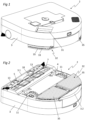
- THE figures 1 to 10 represent an autonomous cleaning robot 2, and more particularly a robot vacuum cleaner, configured to move autonomously over a surface to be cleaned.
- the autonomous cleaning robot 2 comprises a main body 3 having a lower face 4 which is configured to be oriented towards the surface to be cleaned, and a suction mouth 5 which is provided in a front part 3.1 of the main body 3 and which opens into the lower face 4 of the main body 3.
- the suction mouth 5 is elongated and extends in a direction of extension which is perpendicular to a main direction of movement D of the autonomous cleaning robot 2.
- the main body 3 delimits a suction chamber 6 which opens into the lower face 4 of the main body 3 via the suction mouth 5.
- the main body 3 has, seen from above in a substantially vertical orientation, a shape general of D.
- the main body 3 could have a completely different shape, and for example have a general circular or rectangular shape.
- the autonomous cleaning robot 2 further comprises a rotating cleaning brush 7 housed in the suction chamber 6 and mounted to rotate about a brush rotation axis A1 which extends transversely, and more particularly perpendicularly, to the main direction of movement D.
- the brush rotation axis A1 is substantially horizontal when the autonomous cleaning robot 2 rests on a horizontal surface.
- the rotating cleaning brush 7 is configured to eject waste toward a rear portion of the suction chamber 6 at an ejection angle, measured in a median longitudinal plane P of the main body 3, of between 0 and 20°.
- an ejection angle is defined by a minimum ejection trajectory for waste ejected by the rotating cleaning brush 7 and a maximum ejection trajectory for waste ejected by the rotating cleaning brush 7, depending in particular on the type of floor, which may be a hard floor such as tiles or which may be a soft floor, for example carpet, and depending on the type of waste, for example grains of rice or lentils.
- the paths of waste ejected by the rotating cleaning brush 7 according to the minimum and maximum ejection trajectories are shown in dotted lines on the Figure 7 .
- the waste ejection angle and the waste ejection speed depend in particular on the rotational speed of the rotating cleaning brush 7, the brush diameter, the bristle type, the free length of the bristles and the type of floor to be cleaned.
- the rotational speed and the diameter of the rotating cleaning brush 7 make it possible to determine a tangential speed at the periphery of the rotating cleaning brush 7, in other words a tangential speed at the end of the bristles.
- the bristle type and the free length of the bristles determine the flexibility of the bristles which also influences the ejection angle and the waste ejection speed.
- the rotating cleaning brush 7 comprises a brush body 8 which has a central longitudinal axis and which is configured to be driven in rotation in a predetermined direction of rotation, which is shown diagrammatically in the Figure 7 by an arrow rotating counterclockwise, and around the brush rotation axis A1.
- the brush rotation axis A1 is coaxial with the central longitudinal axis of the brush body 8.
- the rotating cleaning brush 7 further comprises one or more rows of bristles 9, for example two rows of bristles, provided on an outer peripheral surface of the brush body 8 and extending over at least part of the length of the brush body 8.
- the rotating cleaning brush 7 could further comprise, or instead of the rows of bristles 9, one or more cleaning strips, for example elastically deformable or rigid, provided on the outer peripheral surface of the brush body 8.
- the rotating cleaning brush 7 may have a brush diameter of between 30 and 60 mm, advantageously between 35 and 45 mm, and for example approximately 41 mm, and the brush body 8 may have an external diameter of between 20 and 40 mm, and for example approximately 33 mm.
- the difference between the external diameter of the brush body 8 and the brush diameter corresponds to twice the free length of the bristles.
- the bristles may have a free length of between 3 and 8 mm and for example approximately 4 mm.
- the bristles are for example made of nylon and advantageously have a diameter of between 0.15 and 0.25 mm.
- the rotating cleaning brush 7 according to the invention has a conventional rotation speed of between approximately 1000 and 5000 revolutions per minute, or approximately 104.7 radians/s to 523.6 radians/s.
- the autonomous cleaning robot 2 also includes a drive mechanism (not visible in the figures) which is configured to drive in rotation of the brush body 8 around the brush rotation axis A1.
- the suction chamber 6 is delimited at least in part by a cylindrical surface portion having a circular section and having a longitudinal axis substantially coaxial with the brush rotation axis A1.
- the difference between the radius of the cylindrical surface portion and a brush radius R of the rotating cleaning brush 7 is between 0.5 and 2 mm.
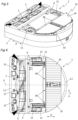
- the autonomous cleaning robot 2 comprises two drive wheels 11 which are configured to roll on the surface to be cleaned.
- the two drive wheels 11 are mounted to be able to rotate relative to the main body 3, and have axes of rotation which are parallel, and advantageously collinear.
- the axes of rotation of the drive wheels 11 extend perpendicular to the main direction of movement D.
- the two drive wheels 11 are configured to protrude from the lower face 4 of the main body 3, and are arranged on either side of the median longitudinal plane P of the main body 3.
- the two drive wheels 11 are arranged symmetrically with respect to the median longitudinal plane P of the main body 3, and are side wheels of the autonomous cleaning robot 2.
- the two drive wheels 11 are advantageously motorized independently of each other.
- the autonomous cleaning robot 2 comprises two rotational drive mechanisms 12 housed in the main body 3 and each configured to rotate a respective drive wheel 11 among the two drive wheels 11.
- Each rotational drive mechanism 12 comprises a drive motor rotatably coupled to the respective drive wheel 11 and arranged for example in a respective lateral portion of the main body 3. According to the control of the two motors aforementioned drive, the main body 3 can pivot left, right or on itself, move forward or even backward.
- the autonomous cleaning robot 2 comprises additional wheels 13 mounted to rotate freely relative to the main body 3, and for example two additional wheels 13 arranged on the front part 3.1 of the main body 3.
- all the additional wheels 13 are located in front of the axes of rotation of the two drive wheels 11, such that the autonomous cleaning robot 2 is devoid of an additional wheel located behind the axes of rotation of the two drive wheels 11.
- the autonomous cleaning robot 2 further comprises a suction unit 14 which is housed in the main body 3.
- the suction unit 14 comprises a suction motor and a fan which is coupled to the suction motor and which is configured to generate an airflow through the suction mouth 5.
- the autonomous cleaning robot 2 also includes a waste collection device 15 (see the Figure 6 ) removably mounted on the main body 3.
- the waste collection device 15 comprises a waste collection container 16 located upstream of the suction unit 14.
- the waste collection container 16 is configured to be traversed by the air flow generated by the fan when the autonomous cleaning robot 2 is in operation, and to retain waste transported by the air flow.
- the autonomous cleaning robot 2 further comprises a connecting channel 17 fluidly connecting the suction chamber 6 to the waste collection container 16.
- the connecting channel 17 has a generally cylindrical shape, and is configured to extend vertically when the autonomous cleaning robot 2 rests on a horizontal surface.
- the connecting channel 17 could be configured to be inclined relative to the vertical by an inclination angle of less than or equal to 10°, and for example less than or equal to 5°, when the autonomous cleaning robot 2 rests on a horizontal surface.
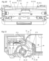
- the connecting channel 17 has an oblong section, but could however have a circular section. As shown more particularly on the Figure 10 , the connecting channel 17 has a first maximum dimension measured parallel to the main direction of movement D of the autonomous cleaning robot 2 and a second maximum dimension measured perpendicular to the median longitudinal plane P of the main body 3, the first maximum dimension being less than the second maximum dimension.
- the connecting channel 17 opens into the rear part of the suction chamber 6, and the median longitudinal plane P of the main body 3 intersects with the connecting channel 17.
- the connecting channel 17 comprises a front wall 17.1, and a rear wall 17.2 which are parallel to each other and which are spaced from each other by a spacing distance D1 which is between 15 and 40 mm, and advantageously between 15 and 25 mm, and for example approximately 20 mm.
- the waste collection container 16 comprises a bottom wall 16.1 which is set back from an upper end of the rear wall 17.2 of the connecting channel 17.
- the autonomous cleaning robot 2 also comprises a lower deflector 18 located at the rear of the brush rotation axis A1 and extending at least partly opposite an inlet opening of the connecting channel 17.
- the lower deflector 18 is elongated and extends parallel to the axis of rotation of the brush A1.
- the lower deflector 18 extends over the entire length of the rotating cleaning brush 7, and forms a rear edge 5.1 of the suction mouth 5.
- the distance between a first vertical plane containing the front edge of the lower deflector 18 and a second vertical plane containing the rear edge of the lower deflector 18 is less than the spacing distance D1.
- the lower deflector 18 comprises a lower deflection surface 19 which partly delimits the suction chamber 6 and which is configured to deflect, upwards and towards the connecting channel 17, waste projected backwards by the rotating cleaning brush 7 onto the lower deflection surface 19.
- the lower deflection surface 19 is flat.
- the lower deflection surface 19 is inclined backwards and upwards, and is configured to be inclined relative to the horizontal by an angle of inclination of between 20 and 55°, advantageously between 25 and 45°, and is for example approximately 37°, when the autonomous cleaning robot 2 rests on a horizontal surface.
- the autonomous cleaning robot 2 further comprises an upper deflector 21 extending at least partly opposite an outlet opening of the connecting channel 17.
- the lower deflector 18 and the upper deflector 21 are located at least partly opposite each other.
- the upper deflector 21 comprises an upper deflection surface 22 which is configured to deflect, rearwardly and towards a lower portion of the waste collection container 16, waste exiting, upwardly, from the connecting channel 17.
- the upper deflection surface 22 may for example be curved and have an aerodynamic profile, such as an aircraft wing profile. According to an alternative embodiment of the invention, the upper deflection surface 22 could be planar and have an inclination, rearwardly and upwardly, substantially identical to that of the lower deflection surface 19.
- the autonomous cleaning robot 2 comprises a partition wall 20 configured to at least partially separate the connecting channel 17 and the waste collection container 16.
- the upper deflection surface 22 is located at a distance from an upper end of the partition wall 20 and delimits, with the partition separation 20, a connecting passage fluidly connecting the connecting channel 17 with the waste collection container 16.
- the separating partition 20 extends from the bottom wall 16.1 of the waste collection container 16.
- the suction chamber 6 has a rear chamber wall 23 (see the figures 9 And 10 ) which is located opposite the rotating cleaning brush 7 and which extends substantially parallel to the brush rotation axis A1.
- the rear chamber wall 23 is located at a separation distance D2 from a vertical plane P1 containing the brush rotation axis A1 and is configured to extend substantially vertically when the autonomous cleaning robot 2 rests on a horizontal surface.
- the separation distance D2 may for example be between 30 and 40 mm, and is for example approximately 34 mm.
- the lower deflector 18 extends to the rear chamber wall 23 and the rear wall 17.2 of the connecting channel 17 extends in the extension of the rear chamber wall 23.
- the lower deflector 18, and thus the lower deflection surface 19 extends from the rear edge 5.1 of the suction mouth 5 to the rear chamber wall 23.
- the rear edge 5.1 of the suction mouth 5 is located at an edge distance D3 from the vertical plane P1 containing the brush rotation axis A1.
- the edge distance D3 corresponds also to the distance between the front edge of the lower deflector 18 and the vertical plane P1 containing the brush rotation axis A1.
- the spacing distance D1 is greater than the difference between the separation distance D2 and the edge distance D3 and is less than the separation distance D2.
- the edge distance D3 is less than the brush radius R of the rotating cleaning brush 7.
- the edge distance D3 can for example be between 15 and 25 mm, and is for example approximately 19 mm.
- the suction chamber 6 comprises a waste deflector 24 comprising a first deflector portion 25 and a second deflector portion 26 located on either side of the inlet opening of the connecting channel 17.
- the first and second deflector portions 25, 26 respectively comprise a first deflection surface 25.1 and a second deflection surface 26.1 which are configured to be oriented towards a surface to be cleaned.
- the first deflection surface 25.1 extends from a first lateral edge of the suction mouth 5 to the inlet opening of the connecting channel 17, and the second deflection surface 26.1 extends from a second lateral edge of the suction mouth 5 to the inlet opening of the connecting channel 17.
- each of the first and second deflection surfaces 25.1, 26.1 is located opposite the lower deflector 18, and more particularly the lower deflection surface 19.
- each of the first and second deflection surfaces 25.1, 26.1 is planar and extends transversely, and for example perpendicularly, to the main direction of movement D of the autonomous cleaning robot 2.
- each of the first and second deflection surfaces 25.1, 26.1 has a width, measured parallel to the main direction of movement of the autonomous cleaning robot, which increases towards the inlet opening of the connecting channel 17.
- the first deflection surface 25.1 is inclined such that the distance between the surface to be cleaned and the first deflection surface 25.1 increases from a first end of the rotating cleaning brush 7 towards the inlet opening of the connecting channel 17, and the second deflection surface 26.1 is inclined such that the distance between the surface to be cleaned and the second deflection surface 26.1 increases from a second end of the rotating cleaning brush 7 towards the inlet opening of the connecting channel 17.
- each of the first and second deflection surfaces 25.1, 26.1 is configured to be inclined relative to the horizontal by an angle of inclination of between 2° and 20°, advantageously between 2° and 10°, and for example approximately 5°, when the autonomous cleaning robot 2 rests on a horizontal surface.
- the suction chamber 6 also comprises a rear deflector 27 comprising a first rear deflector portion 28 and a second rear deflector portion 29 located on either side of the inlet opening of the connecting channel 17 and configured to each extend substantially vertically when the autonomous cleaning robot 2 rests on a horizontal surface.
- the first and second rear deflector portions 28, 29 respectively comprise a first rear deflection surface 28.1 and a second rear deflection surface 29.1 which face the rotating cleaning brush 7 and which are located on either side of the rear chamber wall 23.
- the first rear deflection surface 28.1 extends from the first lateral edge of the suction mouth 5 to the rear chamber wall 23
- the second rear deflection surface 29.1 extends from the second lateral edge of the suction mouth 5 to the rear chamber wall 23.
- each of the first and second rear deflection surfaces 28.1, 29.1 is substantially planar.
- the first rear deflection surface 28.1 is inclined such that the distance between the brush rotation axis A1 and the first rear deflection surface 28.1 increases from the first end of the rotating cleaning brush 7 toward the inlet opening of the connecting channel 17, and the second rear deflection surface 29.1 is inclined such that the distance between the brush rotation axis A1 and the second rear deflection surface 29.1 increases from the second end of the rotating cleaning brush 7 toward the inlet opening of the connecting channel 17.
- each of the first and second rear deflection surfaces 28.1, 29.1 is inclined, relative to a plane perpendicular to the median longitudinal plane P of the main body 3, by an angle of inclination of between 2° and 20°, advantageously between 2° and 10°, and for example approximately 4°.
- the autonomous cleaning robot 2 also comprises a power battery 31 configured to electrically power the autonomous cleaning robot 2.
- the power battery 31 is rechargeable and is housed in the main body 3.
- the autonomous cleaning robot 2 further comprises a wet cleaning device 32 which is arranged in a rear part 3.2 of the main body 3.
- the wet cleaning device 32 is arranged opposite the rotating cleaning brush 7 with respect to the axes of rotation of the drive wheels 11.
- the wet cleaning device 32 comprises two mop supports 33 which are arranged side by side and which are located behind the rotation axes of the drive wheels 11.
- the two mop supports 33 are arranged on either side of the median longitudinal plane P of the main body 3, and are configured to extend substantially horizontally when the main body 3 rests on a horizontal surface.
- the power supply battery 31 is located at least in part, and for example entirely, above one of the mop supports 33, and the suction unit 14 is located at least partly, and for example entirely, above the other of the mop supports 33.
- the suction unit 14 and the power battery 31 are arranged on either side of the median longitudinal plane P of the main body 3.
- the two mop supports 33 are each mounted to be movable in translation relative to the main body 3 in a translation direction T which extends transversely, and advantageously perpendicularly, to the main direction of movement D of the autonomous cleaning robot 2.
- the mop supports 33 are mounted to be movable relative to each other between a close configuration in which the two mop supports 33 are close to each other, and a distant configuration in which the two mop supports 33 are distant from each other.
- the wet cleaning device 32 also comprises a translational drive mechanism 34 configured to move the mop supports 33 in translation in the translation direction T and alternately between the close configuration and the distant configuration.
- the translational drive mechanism 34 is configured to move the two mop supports 33 in translation in phase opposition.
- the translational drive mechanism 34 is located at least partly above the mop supports 33.
- the wet cleaning device 32 further comprises two mops 35 removably mounted respectively on the two mop supports 33.
- the mops 35 are configured to be in contact with the surface to be cleaned, and more particularly to exert a pressing force on the surface to be cleaned, when the autonomous cleaning robot 2 rests on the surface to be cleaned.
- the autonomous cleaning robot 2 is configured such that so that, when the autonomous cleaning robot 2 rests on a surface to be cleaned, a rear part of the autonomous cleaning robot 2 rests on said surface to be cleaned directly by the two mops 35.
- the wet cleaning device 32 is removably mounted relative to the main body 3, and the main body 3 comprises a receiving housing 36 in which the wet cleaning device 32 is received at least in part.
- the wet cleaning device 32 is advantageously configured to be removed from the main body 3 by a translational movement directed towards the rear of the main body 3.
- the autonomous cleaning robot 2 also comprises a cleaning liquid reservoir 37 which is mounted, for example removably, on the main body 3.
- the cleaning liquid reservoir 37 and the waste collection container 16 are superimposed, and are integral with each other.
- the autonomous cleaning robot 2 may for example comprise a removable reservoir comprising a first compartment forming the cleaning liquid reservoir 37 and a second compartment forming the waste collection container 16.
- the cleaning liquid reservoir 37 could be separate from the waste collection device 15, and for example be provided directly on the wet cleaning device 32.
- the wet cleaning device 32 further comprises a plurality of liquid outlets 38 which are configured to be fluidically connected to the cleaning liquid reservoir 37 and which are configured to supply cleaning liquid to the mops 35 mounted on the mop holders 33.
- the liquid outlets 38 are located at the front of the mop holders 33, and for example at the front of the mops 35, and are configured to be oriented towards the surface to be cleaned.
- the autonomous cleaning robot 2 also comprises a cleaning liquid supply circuit (not described in detail) provided on the main body 3 and configured to fluidly connect the liquid outlet ports 38 to the cleaning liquid reservoir 37.
- the cleaning liquid supply circuit may for example comprise in particular a distributor 39 (see the Figure 6 ) housed in the main body 3.
- FIG. 11 represents an autonomous cleaning robot 2 according to a second embodiment of the invention which differs from the first embodiment shown in the figures 1 to 10 essentially in that the upper deflection surface 22 of the upper deflector 21 has a radius of curvature and extends for example over less than a quarter of a circle, in that the cleaning liquid reservoir 37 is offset relative to the waste collection container 16, such that the cleaning liquid reservoir 37 and the waste collection container 16 are not superimposed, and in that the waste collection container 16 has an upper wall which is substantially planar and configured to extend horizontally when the autonomous cleaning robot 2 rests on a horizontal surface.
- the wet cleaning device 32 could be provided with a floor treatment element, other than a mop, configured to carry out a mechanical, chemical, thermal or radiant treatment of the floor.
- the wet cleaning device 32 could comprise at least one passive mop, i.e. one which is mounted immobile relative to the main body 3.
- the autonomous cleaning robot 2 could be devoid of a wet cleaning device 32.
Landscapes
- Nozzles For Electric Vacuum Cleaners (AREA)
- Electric Vacuum Cleaner (AREA)
Claims (15)
- Autonomer Reinigungsroboter (2), umfassend:- einen Hauptkörper (3) mit einer Unterseite (4), die so eingerichtet ist, dass sie zu einer zu reinigenden Oberfläche und einem Ansaugstutzen (5) gerichtet ist, der in die Unterseite (4) des Hauptkörpers (3) mündet, wobei der Hauptkörper (3) eine Ansaugkammer (6) begrenzt, die fluidisch mit dem Ansaugstutzen (5) verbunden ist,- eine rotierende Reinigungsbürste (7), die in der Ansaugkammer (6) untergebracht und um eine Bürstendrehachse (A1) drehbar montiert ist,- eine Ansaugeinheit (14), die mindestens teilweise im Hauptkörper (3) untergebracht ist und die so eingerichtet ist, dass sie einen Luftstrom durch den Ansaugstutzen (5) erzeugt,- eine Abfallsammelvorrichtung (15), die einen Abfallsammelbehälter (16) umfasst, der der Ansaugeinheit (14) vorgelagert ist und so eingerichtet ist, dass er vom von der Ansaugeinheit (14) erzeugten Luftstrom durchquert wird und Abfall zurückhält, der durch den Luftstrom transportiert wird, und- einen Verbindungskanal (17), der die Ansaugkammer (6) fluidisch mit dem Abfallsammelbehälter (16) verbindet, wobei der Verbindungskanal (17) eine Einlassöffnung umfasst, die in die Ansaugkammer (6) mündet,dadurch gekennzeichnet, dass die Ansaugkammer (6) eine Abfallumlenkung (24) aufweist, die einen ersten Umlenkabschnitt (25) und einen zweiten Umlenkabschnitt (26) umfasst, die sich auf beiden Seiten der Eingangsöffnung des Verbindungskanals (17) befinden, wobei der erste und der zweite Umlenkabschnitt (25, 26) jeweils eine erste Umlenkfläche (25.1) und eine zweite Umlenkfläche (26.1) aufweisen die so eingerichtet sind, dass sie auf die zu reinigende Fläche ausgerichtet sind und sich quer zu einer Hauptbewegungsrichtung (D) des autonomen Reinigungsroboters (2) erstrecken, wobei die erste Umlenkfläche (25.1) so geneigt ist, dass der Abstand zwischen der zu reinigenden Fläche und der ersten Umlenkfläche (25.1) in Richtung der Eingangsöffnung des Verbindungskanals (17) zunimmt, wobei die zweite Umlenkfläche (26.1) so geneigt sein, dass sich der Abstand zwischen der zu reinigenden Fläche und der zweiten Umlenkfläche (26.1) in Richtung der Eintrittsöffnung des Verbindungskanals (17) vergrößert.
- Autonomer Reinigungsroboter (2) nach Anspruch 1, wobei jede der ersten und zweiten Umlenkflächen (25.1, 26.1) so eingerichtet ist, dass sie in Bezug auf die Horizontale um einen Neigungswinkel zwischen 2° und 20° geneigt ist, wenn der autonome Reinigungsroboter (2) auf einer horizontalen Oberfläche ruht.
- Autonomer Reinigungsroboter (2) nach Anspruch 1 oder 2, wobei jede der ersten und zweiten Umlenkflächen (25.1, 26.1) eine Breite aufweist, gemessen parallel zur Hauptbewegungsrichtung (D) des autonomen Reinigungsroboters (2), die in Richtung der Eingangsöffnung des Verbindungskanals (17) zunimmt.
- Autonomer Reinigungsroboter (2) nach einem der Ansprüche 1 bis 3, wobei jede der ersten und zweiten Umlenkflächen (25.1, 26.1) im Wesentlichen eben ist.
- Autonomer Reinigungsroboter (2) nach einem der Ansprüche 1 bis 4, der ferner eine untere Umlenkung (18) aufweist, der sich hinter der Bürstendrehachse (A1) befindet und sich mindestens teilweise gegenüber der Eingangsöffnung des Verbindungskanals (17) erstreckt, wobei die untere Umlenkung (18) eine untere Umlenkfläche (19) umfasst, die die Ansaugkammer (6) teilweise begrenzt und die so eingerichtet ist, dass sie nach oben und in Richtung des Verbindungskanals (17) Abfall umleitet, der von der rotierenden Reinigungsbürste (7) auf die untere Umlenkfläche (19) geschleudert werden.
- Autonomer Reinigungsroboter (2) nach Anspruch 5, wobei sich jede der ersten und zweiten Umlenkflächen (25.1, 26.1) gegenüber der unteren Umlenkung (18) befindet.
- Autonomer Reinigungsroboter (2) nach Anspruch 5 oder 6, wobei die untere Umlenkung (18) eine Hinterkante (5.1) des Ansaugstutzens (5) bildet.
- Autonomer Reinigungsroboter (2) nach einem der Ansprüche 5 bis 7, wobei die untere Umlenkfläche (19) nach hinten und oben geneigt ist und so eingerichtet ist, dass sie in Bezug auf die Horizontale um einen Neigungswinkel zwischen 20 und 55° geneigt ist, wenn der autonome Reinigungsroboter (2) auf einer horizontalen Oberfläche ruht.
- Autonomer Reinigungsroboter (2) nach einem der Ansprüche 1 bis 8, der ferner eine zumindest teilweise gegenüber einer Austrittsöffnung des Verbindungskanals (17) erstreckende obere Umlenkung (21) aufweist, wobei die obere Umlenkung (21) eine obere Umlenkfläche (22) aufweist, die so eingerichtet ist, dass sie Abfall, der nach oben aus dem Verbindungskanal (17) austritt, nach hinten in den Abfallsammelbehälter (16) umleitet.
- Autonomer Reinigungsroboter (2) nach Anspruch 5 und 9, wobei sich die untere Umlenkung (18) und die obere Umlenkung (21) mindestens teilweise gegenüberliegend zueinander befinden.
- Autonomer Reinigungsroboter (2) nach einem der Ansprüche 1 bis 10, wobei die Ansaugkammer (6) eine hintere Umlenkung (27) aufweist, die einen ersten hinteren Umlenkabschnitt (28) und einen zweiten hinteren Umlenkabschnitt (29) umfasst, die sich auf beiden Seiten der Eingangsöffnung des Verbindungskanals (17) befinden und so eingerichtet sind, dass sie sich jeweils im Wesentlichen vertikal ausdehnen, wenn der autonome Reinigungsroboter (2) auf einer horizontalen Oberfläche ruht, der erste und zweite hintere Umlenkabschnitt (28, 29) jeweils eine erste hintere Umlenkfläche (28.1) und eine zweite hintere Umlenkfläche (29.1) aufweisen, die der rotierenden Reinigungsbürste (7) zugewandt sind, wobei die erste hintere Umlenkfläche (28.1) so geneigt ist, dass der Abstand zwischen der Bürstendrehachse (A1) und der ersten hinteren Umlenkfläche (28.1) in Richtung der Eingangsöffnung des Verbindungskanals (17) zunimmt, und die zweite hintere Umlenkfläche (29.1) so geneigt ist, dass sich der Abstand zwischen der Bürstendrehachse (A1) und der zweiten hinteren Umlenkfläche (29.1) in Richtung der Eintrittsöffnung des Verbindungskanals (17) vergrößert.
- Autonomer Reinigungsroboter (2) nach Anspruch 11, wobei jede der ersten und zweiten hinteren Umlenkflächen (28.1, 29.1) in Bezug auf eine senkrechte Querebene senkrecht zur Hauptbewegungsrichtung (D) des autonomen Reinigungsroboters (2) um einen Neigungswinkel zwischen 2° und 20° geneigt ist.
- Autonomer Reinigungsroboter (2) nach einem der Ansprüche 1 bis 12, wobei der Verbindungskanal (17) eine insgesamt zylindrische Form aufweist und so eingerichtet ist, dass er sich im Wesentlichen vertikal erstreckt, wenn der autonome Reinigungsroboter (2) auf einer horizontalen Oberfläche aufliegt.
- Autonomer Reinigungsroboter (2) nach einem der Ansprüche 1 bis 13, wobei der Verbindungskanal (17) in einen hinteren Teil der Ansaugkammer (6) mündet.
- Autonomer Reinigungsroboter (2) nach einem der Ansprüche 1 bis 14, der ferner eine Nassreinigungsvorrichtung (32) umfasst, die mindestens einen Mopphalter (33) umfasst, der am Hauptkörper (3) montiert ist, und mindestens einen Mopp (35), der beweglich an dem mindestens einen Mopphalter (33) montiert und so eingerichtet ist, dass er mit der zu reinigenden Oberfläche in Kontakt steht.
Applications Claiming Priority (1)
| Application Number | Priority Date | Filing Date | Title |
|---|---|---|---|
| FR2214104A FR3143962B1 (fr) | 2022-12-21 | 2022-12-21 | Robot de nettoyage autonome équipé de déflecteurs de déchets |
Publications (2)
| Publication Number | Publication Date |
|---|---|
| EP4388959A1 EP4388959A1 (de) | 2024-06-26 |
| EP4388959B1 true EP4388959B1 (de) | 2025-05-28 |
Family
ID=85936833
Family Applications (1)
| Application Number | Title | Priority Date | Filing Date |
|---|---|---|---|
| EP23216591.0A Active EP4388959B1 (de) | 2022-12-21 | 2023-12-14 | Autonomer reinigungsroboter mit abfalldeflektoren |
Country Status (7)
| Country | Link |
|---|---|
| EP (1) | EP4388959B1 (de) |
| JP (1) | JP2025542170A (de) |
| KR (1) | KR20250127283A (de) |
| CN (1) | CN118216829A (de) |
| ES (1) | ES3035965T3 (de) |
| FR (1) | FR3143962B1 (de) |
| WO (1) | WO2024134067A1 (de) |
Family Cites Families (3)
| Publication number | Priority date | Publication date | Assignee | Title |
|---|---|---|---|---|
| KR20080087596A (ko) * | 2007-03-27 | 2008-10-01 | 삼성전자주식회사 | 로봇청소기 |
| DE102010060479B4 (de) * | 2010-11-10 | 2023-03-23 | Vorwerk & Co. Interholding Gmbh | Kehrgerät |
| KR20160025392A (ko) * | 2014-08-27 | 2016-03-08 | 에브리봇 주식회사 | 흡입 노즐, 로봇 청소기 및 그의 제어 방법 |
-
2022
- 2022-12-21 FR FR2214104A patent/FR3143962B1/fr active Active
-
2023
- 2023-12-14 EP EP23216591.0A patent/EP4388959B1/de active Active
- 2023-12-14 KR KR1020257023826A patent/KR20250127283A/ko active Pending
- 2023-12-14 ES ES23216591T patent/ES3035965T3/es active Active
- 2023-12-14 WO PCT/FR2023/052010 patent/WO2024134067A1/fr not_active Ceased
- 2023-12-14 JP JP2025534717A patent/JP2025542170A/ja active Pending
- 2023-12-20 CN CN202311755932.2A patent/CN118216829A/zh active Pending
Also Published As
| Publication number | Publication date |
|---|---|
| EP4388959A1 (de) | 2024-06-26 |
| CN118216829A (zh) | 2024-06-21 |
| FR3143962A1 (fr) | 2024-06-28 |
| FR3143962B1 (fr) | 2024-12-20 |
| JP2025542170A (ja) | 2025-12-25 |
| WO2024134067A1 (fr) | 2024-06-27 |
| KR20250127283A (ko) | 2025-08-26 |
| ES3035965T3 (en) | 2025-09-11 |
Similar Documents
| Publication | Publication Date | Title |
|---|---|---|
| EP4115785B1 (de) | Autonomer reinigungsroboter, der mit einer nassreinigungsvorrichtung ausgestattet ist | |
| WO2009125130A2 (fr) | Appareil nettoyeur de surface immergée à protubérance accélératrice du flux d'entrée | |
| FR2961838A1 (fr) | Appareil automobile nettoyeur de surface immergee | |
| EP4388959B1 (de) | Autonomer reinigungsroboter mit abfalldeflektoren | |
| EP4393368B1 (de) | Autonomer reinigungsroboter mit abfalldeflektoren | |
| EP4046557B1 (de) | Roboterstaubsauger, der mit mindestens einem festen seitlichen reinigungselement ausgestattet ist | |
| EP4388955B1 (de) | Autonomer reinigungsroboter mit nassreinigungsvorrichtung | |
| EP4473889B1 (de) | Reinigungsvorrichtung mit einem abfallleitkanal | |
| EP4473888B1 (de) | Reinigungsvorrichtung mit einem abfallleitkanal | |
| EP4563052A1 (de) | Autonomer reinigungsroboter | |
| EP4473890B1 (de) | Reinigungsvorrichtung mit einem abfallleitkanal | |
| EP4566498A1 (de) | Autonomer reinigungsroboter mit zwei festen seitenreinigungselementen | |
| WO2020070217A1 (fr) | Balai de nettoyage de sol a fonction electrique | |
| FR3159307A1 (fr) | Procédé de commande d’un système de nettoyage autonome pourvu d’une station d’accueil équipée d’organes de grattage | |
| FR3138290A1 (fr) | Tête d’aspiration équipée d’une brosse rotative pourvue d’une lamelle de nettoyage | |
| FR3155696A1 (fr) | Robot de nettoyage autonome équipé d’un dispositif de nettoyage | |
| EP4039148A1 (de) | Schlittenartige ansaugeinheit, die mit einer zyklonabscheidevorrichtung ausgestattet ist | |
| FR3119529A1 (fr) | Ensemble d’aspiration équipé d’une structure de protection d’un dispositif de séparation et de collecte de déchets | |
| FR3119524A1 (fr) | Appareil de nettoyage avec structure de protection |
Legal Events
| Date | Code | Title | Description |
|---|---|---|---|
| PUAI | Public reference made under article 153(3) epc to a published international application that has entered the european phase |
Free format text: ORIGINAL CODE: 0009012 |
|
| STAA | Information on the status of an ep patent application or granted ep patent |
Free format text: STATUS: THE APPLICATION HAS BEEN PUBLISHED |
|
| AK | Designated contracting states |
Kind code of ref document: A1 Designated state(s): AL AT BE BG CH CY CZ DE DK EE ES FI FR GB GR HR HU IE IS IT LI LT LU LV MC ME MK MT NL NO PL PT RO RS SE SI SK SM TR |
|
| STAA | Information on the status of an ep patent application or granted ep patent |
Free format text: STATUS: REQUEST FOR EXAMINATION WAS MADE |
|
| 17P | Request for examination filed |
Effective date: 20241125 |
|
| RBV | Designated contracting states (corrected) |
Designated state(s): AL AT BE BG CH CY CZ DE DK EE ES FI FR GB GR HR HU IE IS IT LI LT LU LV MC ME MK MT NL NO PL PT RO RS SE SI SK SM TR |
|
| GRAP | Despatch of communication of intention to grant a patent |
Free format text: ORIGINAL CODE: EPIDOSNIGR1 |
|
| STAA | Information on the status of an ep patent application or granted ep patent |
Free format text: STATUS: GRANT OF PATENT IS INTENDED |
|
| RIC1 | Information provided on ipc code assigned before grant |
Ipc: A47L 11/12 20060101AFI20241217BHEP |
|
| INTG | Intention to grant announced |
Effective date: 20250103 |
|
| P01 | Opt-out of the competence of the unified patent court (upc) registered |
Free format text: CASE NUMBER: APP_10889/2025 Effective date: 20250305 |
|
| GRAS | Grant fee paid |
Free format text: ORIGINAL CODE: EPIDOSNIGR3 |
|
| GRAA | (expected) grant |
Free format text: ORIGINAL CODE: 0009210 |
|
| STAA | Information on the status of an ep patent application or granted ep patent |
Free format text: STATUS: THE PATENT HAS BEEN GRANTED |
|
| AK | Designated contracting states |
Kind code of ref document: B1 Designated state(s): AL AT BE BG CH CY CZ DE DK EE ES FI FR GB GR HR HU IE IS IT LI LT LU LV MC ME MK MT NL NO PL PT RO RS SE SI SK SM TR |
|
| REG | Reference to a national code |
Ref country code: GB Ref legal event code: FG4D Free format text: NOT ENGLISH |
|
| REG | Reference to a national code |
Ref country code: CH Ref legal event code: EP |
|
| REG | Reference to a national code |
Ref country code: IE Ref legal event code: FG4D Free format text: LANGUAGE OF EP DOCUMENT: FRENCH Ref country code: DE Ref legal event code: R096 Ref document number: 602023003709 Country of ref document: DE |
|
| REG | Reference to a national code |
Ref country code: ES Ref legal event code: FG2A Ref document number: 3035965 Country of ref document: ES Kind code of ref document: T3 Effective date: 20250911 |
|
| REG | Reference to a national code |
Ref country code: NL Ref legal event code: MP Effective date: 20250528 |
|
| PG25 | Lapsed in a contracting state [announced via postgrant information from national office to epo] |
Ref country code: FI Free format text: LAPSE BECAUSE OF FAILURE TO SUBMIT A TRANSLATION OF THE DESCRIPTION OR TO PAY THE FEE WITHIN THE PRESCRIBED TIME-LIMIT Effective date: 20250528 |
|
| REG | Reference to a national code |
Ref country code: LT Ref legal event code: MG9D |
|
| PG25 | Lapsed in a contracting state [announced via postgrant information from national office to epo] |
Ref country code: NO Free format text: LAPSE BECAUSE OF FAILURE TO SUBMIT A TRANSLATION OF THE DESCRIPTION OR TO PAY THE FEE WITHIN THE PRESCRIBED TIME-LIMIT Effective date: 20250828 Ref country code: GR Free format text: LAPSE BECAUSE OF FAILURE TO SUBMIT A TRANSLATION OF THE DESCRIPTION OR TO PAY THE FEE WITHIN THE PRESCRIBED TIME-LIMIT Effective date: 20250829 |
|
| PG25 | Lapsed in a contracting state [announced via postgrant information from national office to epo] |
Ref country code: NL Free format text: LAPSE BECAUSE OF FAILURE TO SUBMIT A TRANSLATION OF THE DESCRIPTION OR TO PAY THE FEE WITHIN THE PRESCRIBED TIME-LIMIT Effective date: 20250528 Ref country code: PL Free format text: LAPSE BECAUSE OF FAILURE TO SUBMIT A TRANSLATION OF THE DESCRIPTION OR TO PAY THE FEE WITHIN THE PRESCRIBED TIME-LIMIT Effective date: 20250528 |
|
| PG25 | Lapsed in a contracting state [announced via postgrant information from national office to epo] |
Ref country code: BG Free format text: LAPSE BECAUSE OF FAILURE TO SUBMIT A TRANSLATION OF THE DESCRIPTION OR TO PAY THE FEE WITHIN THE PRESCRIBED TIME-LIMIT Effective date: 20250528 |
|
| PG25 | Lapsed in a contracting state [announced via postgrant information from national office to epo] |
Ref country code: HR Free format text: LAPSE BECAUSE OF FAILURE TO SUBMIT A TRANSLATION OF THE DESCRIPTION OR TO PAY THE FEE WITHIN THE PRESCRIBED TIME-LIMIT Effective date: 20250528 |
|
| PG25 | Lapsed in a contracting state [announced via postgrant information from national office to epo] |
Ref country code: RS Free format text: LAPSE BECAUSE OF FAILURE TO SUBMIT A TRANSLATION OF THE DESCRIPTION OR TO PAY THE FEE WITHIN THE PRESCRIBED TIME-LIMIT Effective date: 20250828 |
|
| PG25 | Lapsed in a contracting state [announced via postgrant information from national office to epo] |
Ref country code: IS Free format text: LAPSE BECAUSE OF FAILURE TO SUBMIT A TRANSLATION OF THE DESCRIPTION OR TO PAY THE FEE WITHIN THE PRESCRIBED TIME-LIMIT Effective date: 20250928 |
|
| PG25 | Lapsed in a contracting state [announced via postgrant information from national office to epo] |
Ref country code: LV Free format text: LAPSE BECAUSE OF FAILURE TO SUBMIT A TRANSLATION OF THE DESCRIPTION OR TO PAY THE FEE WITHIN THE PRESCRIBED TIME-LIMIT Effective date: 20250528 |
|
| REG | Reference to a national code |
Ref country code: AT Ref legal event code: MK05 Ref document number: 1798133 Country of ref document: AT Kind code of ref document: T Effective date: 20250528 |
|
| PG25 | Lapsed in a contracting state [announced via postgrant information from national office to epo] |
Ref country code: AT Free format text: LAPSE BECAUSE OF FAILURE TO SUBMIT A TRANSLATION OF THE DESCRIPTION OR TO PAY THE FEE WITHIN THE PRESCRIBED TIME-LIMIT Effective date: 20250528 Ref country code: DK Free format text: LAPSE BECAUSE OF FAILURE TO SUBMIT A TRANSLATION OF THE DESCRIPTION OR TO PAY THE FEE WITHIN THE PRESCRIBED TIME-LIMIT Effective date: 20250528 Ref country code: SM Free format text: LAPSE BECAUSE OF FAILURE TO SUBMIT A TRANSLATION OF THE DESCRIPTION OR TO PAY THE FEE WITHIN THE PRESCRIBED TIME-LIMIT Effective date: 20250528 |
|
| PGFP | Annual fee paid to national office [announced via postgrant information from national office to epo] |
Ref country code: FR Payment date: 20251230 Year of fee payment: 3 |
|
| PG25 | Lapsed in a contracting state [announced via postgrant information from national office to epo] |
Ref country code: CZ Free format text: LAPSE BECAUSE OF FAILURE TO SUBMIT A TRANSLATION OF THE DESCRIPTION OR TO PAY THE FEE WITHIN THE PRESCRIBED TIME-LIMIT Effective date: 20250528 |
|
| PG25 | Lapsed in a contracting state [announced via postgrant information from national office to epo] |
Ref country code: EE Free format text: LAPSE BECAUSE OF FAILURE TO SUBMIT A TRANSLATION OF THE DESCRIPTION OR TO PAY THE FEE WITHIN THE PRESCRIBED TIME-LIMIT Effective date: 20250528 |
|
| PG25 | Lapsed in a contracting state [announced via postgrant information from national office to epo] |
Ref country code: SK Free format text: LAPSE BECAUSE OF FAILURE TO SUBMIT A TRANSLATION OF THE DESCRIPTION OR TO PAY THE FEE WITHIN THE PRESCRIBED TIME-LIMIT Effective date: 20250528 |
|
| PG25 | Lapsed in a contracting state [announced via postgrant information from national office to epo] |
Ref country code: RO Free format text: LAPSE BECAUSE OF FAILURE TO SUBMIT A TRANSLATION OF THE DESCRIPTION OR TO PAY THE FEE WITHIN THE PRESCRIBED TIME-LIMIT Effective date: 20250528 |