EP4388872A1 - Multiple nozzle holder for an agricultural spraying system - Google Patents
Multiple nozzle holder for an agricultural spraying system Download PDFInfo
- Publication number
- EP4388872A1 EP4388872A1 EP23210742.5A EP23210742A EP4388872A1 EP 4388872 A1 EP4388872 A1 EP 4388872A1 EP 23210742 A EP23210742 A EP 23210742A EP 4388872 A1 EP4388872 A1 EP 4388872A1
- Authority
- EP
- European Patent Office
- Prior art keywords
- plate
- valve
- nozzle holder
- valves
- contact
- Prior art date
- Legal status (The legal status is an assumption and is not a legal conclusion. Google has not performed a legal analysis and makes no representation as to the accuracy of the status listed.)
- Pending
Links
- 238000005507 spraying Methods 0.000 title description 11
- 238000009826 distribution Methods 0.000 claims abstract description 41
- 230000002093 peripheral effect Effects 0.000 claims abstract description 15
- 239000007788 liquid Substances 0.000 claims description 39
- 239000007921 spray Substances 0.000 claims description 12
- 238000007789 sealing Methods 0.000 claims description 6
- 230000006835 compression Effects 0.000 claims description 3
- 238000007906 compression Methods 0.000 claims description 3
- 230000007246 mechanism Effects 0.000 claims description 3
- 239000012530 fluid Substances 0.000 description 11
- 208000031968 Cadaver Diseases 0.000 description 5
- 230000009467 reduction Effects 0.000 description 2
- 230000000284 resting effect Effects 0.000 description 2
- 210000002105 tongue Anatomy 0.000 description 2
- 230000009471 action Effects 0.000 description 1
- 239000003518 caustics Substances 0.000 description 1
- 230000008859 change Effects 0.000 description 1
- 239000013043 chemical agent Substances 0.000 description 1
- 231100001010 corrosive Toxicity 0.000 description 1
- 229920001971 elastomer Polymers 0.000 description 1
- 239000000806 elastomer Substances 0.000 description 1
- 238000005461 lubrication Methods 0.000 description 1
- 238000004519 manufacturing process Methods 0.000 description 1
- 239000000463 material Substances 0.000 description 1
- 238000000034 method Methods 0.000 description 1
- 230000004048 modification Effects 0.000 description 1
- 238000012986 modification Methods 0.000 description 1
- 230000004044 response Effects 0.000 description 1
- 230000000717 retained effect Effects 0.000 description 1
- 238000005096 rolling process Methods 0.000 description 1
- 238000000926 separation method Methods 0.000 description 1
- 230000007704 transition Effects 0.000 description 1
Images


Classifications
-
- B—PERFORMING OPERATIONS; TRANSPORTING
- B05—SPRAYING OR ATOMISING IN GENERAL; APPLYING FLUENT MATERIALS TO SURFACES, IN GENERAL
- B05B—SPRAYING APPARATUS; ATOMISING APPARATUS; NOZZLES
- B05B1/00—Nozzles, spray heads or other outlets, with or without auxiliary devices such as valves, heating means
- B05B1/14—Nozzles, spray heads or other outlets, with or without auxiliary devices such as valves, heating means with multiple outlet openings; with strainers in or outside the outlet opening
- B05B1/16—Nozzles, spray heads or other outlets, with or without auxiliary devices such as valves, heating means with multiple outlet openings; with strainers in or outside the outlet opening having selectively- effective outlets
- B05B1/1609—Nozzles, spray heads or other outlets, with or without auxiliary devices such as valves, heating means with multiple outlet openings; with strainers in or outside the outlet opening having selectively- effective outlets with a selecting mechanism comprising a lift valve
-
- A—HUMAN NECESSITIES
- A01—AGRICULTURE; FORESTRY; ANIMAL HUSBANDRY; HUNTING; TRAPPING; FISHING
- A01G—HORTICULTURE; CULTIVATION OF VEGETABLES, FLOWERS, RICE, FRUIT, VINES, HOPS OR SEAWEED; FORESTRY; WATERING
- A01G7/00—Botany in general
- A01G7/06—Treatment of growing trees or plants, e.g. for preventing decay of wood, for tingeing flowers or wood, for prolonging the life of plants
-
- A—HUMAN NECESSITIES
- A01—AGRICULTURE; FORESTRY; ANIMAL HUSBANDRY; HUNTING; TRAPPING; FISHING
- A01M—CATCHING, TRAPPING OR SCARING OF ANIMALS; APPARATUS FOR THE DESTRUCTION OF NOXIOUS ANIMALS OR NOXIOUS PLANTS
- A01M7/00—Special adaptations or arrangements of liquid-spraying apparatus for purposes covered by this subclass
- A01M7/0025—Mechanical sprayers
- A01M7/0032—Pressure sprayers
-
- A—HUMAN NECESSITIES
- A01—AGRICULTURE; FORESTRY; ANIMAL HUSBANDRY; HUNTING; TRAPPING; FISHING
- A01M—CATCHING, TRAPPING OR SCARING OF ANIMALS; APPARATUS FOR THE DESTRUCTION OF NOXIOUS ANIMALS OR NOXIOUS PLANTS
- A01M7/00—Special adaptations or arrangements of liquid-spraying apparatus for purposes covered by this subclass
- A01M7/005—Special arrangements or adaptations of the spraying or distributing parts, e.g. adaptations or mounting of the spray booms, mounting of the nozzles, protection shields
- A01M7/006—Mounting of the nozzles
-
- B—PERFORMING OPERATIONS; TRANSPORTING
- B05—SPRAYING OR ATOMISING IN GENERAL; APPLYING FLUENT MATERIALS TO SURFACES, IN GENERAL
- B05B—SPRAYING APPARATUS; ATOMISING APPARATUS; NOZZLES
- B05B1/00—Nozzles, spray heads or other outlets, with or without auxiliary devices such as valves, heating means
- B05B1/14—Nozzles, spray heads or other outlets, with or without auxiliary devices such as valves, heating means with multiple outlet openings; with strainers in or outside the outlet opening
-
- B—PERFORMING OPERATIONS; TRANSPORTING
- B05—SPRAYING OR ATOMISING IN GENERAL; APPLYING FLUENT MATERIALS TO SURFACES, IN GENERAL
- B05B—SPRAYING APPARATUS; ATOMISING APPARATUS; NOZZLES
- B05B1/00—Nozzles, spray heads or other outlets, with or without auxiliary devices such as valves, heating means
- B05B1/30—Nozzles, spray heads or other outlets, with or without auxiliary devices such as valves, heating means designed to control volume of flow, e.g. with adjustable passages
- B05B1/3013—Nozzles, spray heads or other outlets, with or without auxiliary devices such as valves, heating means designed to control volume of flow, e.g. with adjustable passages the controlling element being a lift valve
-
- B—PERFORMING OPERATIONS; TRANSPORTING
- B05—SPRAYING OR ATOMISING IN GENERAL; APPLYING FLUENT MATERIALS TO SURFACES, IN GENERAL
- B05B—SPRAYING APPARATUS; ATOMISING APPARATUS; NOZZLES
- B05B15/00—Details of spraying plant or spraying apparatus not otherwise provided for; Accessories
- B05B15/60—Arrangements for mounting, supporting or holding spraying apparatus
- B05B15/65—Mounting arrangements for fluid connection of the spraying apparatus or its outlets to flow conduits
- B05B15/658—Mounting arrangements for fluid connection of the spraying apparatus or its outlets to flow conduits the spraying apparatus or its outlet axis being perpendicular to the flow conduit
-
- B—PERFORMING OPERATIONS; TRANSPORTING
- B05—SPRAYING OR ATOMISING IN GENERAL; APPLYING FLUENT MATERIALS TO SURFACES, IN GENERAL
- B05B—SPRAYING APPARATUS; ATOMISING APPARATUS; NOZZLES
- B05B15/00—Details of spraying plant or spraying apparatus not otherwise provided for; Accessories
- B05B15/70—Arrangements for moving spray heads automatically to or from the working position
Definitions
- the present invention relates to the field of agricultural spraying systems. More specifically, the invention relates to spraying devices, comprising in particular multiple nozzle holders, that is to say carrying a plurality of spraying nozzles.
- An agricultural spray boom generally includes nozzle holders distributed uniformly over the entire length of the spray boom, for spraying phytosanitary product in liquid form onto rows of plants.
- nozzle holders distributed uniformly over the entire length of the spray boom, for spraying phytosanitary product in liquid form onto rows of plants.
- it is necessary to vary the spray flow rate of the nozzles and control it proportionally to the forward speed of the agricultural machine supporting the spray boom and/or depending on the product sprayed for example.
- nozzle holders supporting several nozzles are known, for example different nozzles or nozzles having different flow rates.
- Nozzle holders are thus known comprising a plurality of nozzles which can be active simultaneously, and having an identical flow rate or not. These nozzle holders are generally automatically controllable by means of an electric actuator, making it possible to select the active nozzle(s) by means of an active nozzle selection device.
- the document EP 2801410 B1 describes such an example of a nozzle holder having a plurality of nozzles, including a main body, a distribution chamber and a plurality of valves configured to leave open or to close corresponding passages to the plurality of nozzles.
- nozzle holders have the major disadvantage of seeing the entire mechanism for selecting the activated nozzles bathed in the fluid distributed by the spraying device.
- the product in the context of spraying a phytosanitary product, the product is in contact with mechanical components which risk polluting said product before spraying.
- contact with a fluid which may include chemical agents, for example corrosives, harms the lifespan of the device and is incompatible with a need for lubrication of the moving mechanical elements, which also reduces their lifespan.
- the entire device must be waterproof, all of these constraints limiting the choice of materials usable for the manufacture of the nozzle holder.
- the invention aims to resolve the drawbacks of the state of the art, in particular by proposing a nozzle holder comprising a plurality of nozzles which can be active simultaneously, in which the number of mechanical components in contact with the fluid is limited.
- the mechanical components involved in the kinematic chain of control of such a nozzle holder are isolated from a phytosanitary fluid circulating from a spray line towards the spray heads.
- a user can thus freely and remotely control the active nozzle without manual intervention, which simplifies the effective operating time of said nozzle holder.
- the response time for moving a valve from the open position to the closed position or from the closed position to the open position is not only configurable by the rotation speed transmitted by the actuator to the plate, but also by the inclination of the slope portions of the peripheral edge of the plateau.
- valves of the plurality of valves are in the open position simultaneously, each first valve end contact surface being in contact with a single first edge of the plate.
- a fluid circulating in the nozzle holder can thus be sprayed by a plurality of nozzles simultaneously.
- each first edge portion extends circumferentially along a given circular sector.
- the circular sectors of each of the first edges can be different from each other, so that for a complete revolution of the plate, the contact between the first valve end contact surface is mainly with the edge portions high or mainly with low border portions.
- the nozzle holder comprises an even number of valves associated in pairs, the associated valves being arranged symmetrically with respect to a reference plane perpendicular to the plate, said plate comprising at least one given angular position for each pair of associated valves in a simultaneous opening position of said pair of valves
- the distribution chamber is supplied by two branches of the intake pipe, each branch opening into the distribution chamber on a different side of the reference plane. In such a configuration, each half of the plurality of valves is fed simultaneously through the intake line, thereby increasing the flow rate of filling the nozzle holder.
- the separation of the intake pipe into two branches makes it possible to reduce the singular pressure losses of the flow of a fluid in the nozzle holder.
- each valve further comprises a mechanical compression spring linking the valve to the walls of the distribution chamber of the body; a second valve end configured to sealingly close the passage orifices of the distribution chamber in the valve closed position, said second end further comprising sealing means.
- the mechanical spring keeps the valve in the closed position.
- the first contact end surface is carried by a tooth in contact with the peripheral edge of the plate.
- any rotation of a valve is blocked.
- the sliding of the tooth on the edge of the plate is facilitated, in particular on the transitional zones, for example when passing from the contact from a high portion to a sloping portion.
- an axis of rotation of the actuator is offset radially relative to an axis of rotation of the plate.
- a directional axis of the supply line can intersect the axis of rotation of the movable plate, which provides better balance when attaching the nozzle holder to said supply line.
- the actuator for example a stepper electric motor, can occupy a free volume depending on the desired motor power.
- the actuator comprises a pinion forming a gear connection with teeth of the plate.
- the teeth of the plate occupy a circular sector greater than or equal to 120°.
- the nozzle holder comprises at least one stop valve fixed to the body to control the pressure of a liquid circulating in the inlet pipe.
- the shut-off valve is preferably a solenoid shut-off valve. More preferably, the solenoid valve controls the pressure of the liquid circulating in the intake pipe by pulse width modulation signals.
- the stop valve may be a mechanical or pneumatic drip stop.
- such a fixing device makes it possible both to fix a nozzle holder to a fluid supply line while ensuring a function of fixing a casing to a nozzle holder comprising for example an actuator such as a stepper electric motor configured to supply mechanical energy to the nozzle holder.
- the fixing device further allows a nozzle holder architecture in which the majority of the mass of the casing is directly aligned with the supply line and the nozzle holder, which limits the risk of the nozzle holder pivoting under the action of a moment generated by the weight of the casing.
- the fixing device comprises a first receiving support located on one side of the nozzle holder and a second fixing support located on another side of the nozzle holder.
- the hinges of the two receiving supports each pivot relative to a pivot axis located on either side of the supply line.
- each of the pins pivots in one direction of rotation, which prevents the risk of accidental opening of the fixing device and the fall of the nozzle holder from the supply line.
- the clamp includes a curved tab.
- the curved tab allows a user to exert sufficient pressure to engage the hose clamp onto the supply line or to disengage the hose clamp to the free position of the pin.
- each latch comprises a locking means in the closed position on the receiving support so that said locking means is retained by a stop of the receiving support when the fixing device is subjected to the weight of the nozzle holder.
- a locking means makes it easier to position the nozzle holder on the supply line before assembling the casing with the body of the nozzle holder followed by inserting the pin and snapping in the collar tightening on the supply line.
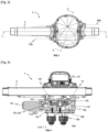
- THE figures 1 to 5 illustrate a nozzle holder 1 configured to be part of a spraying system.
- the nozzle holder 1 is intended to be fixed to a supply line 2 and to be for example carried or dragged by a vehicle, in particular an agricultural machine.
- the nozzle holder 1 comprises a body, in particular prismatic, having the function of housing the different components of the nozzle holder 1.
- the body is preferably formed from an upper body part 10a, an intermediate body part 10b and a lower body part 10c.
- the upper part 10a is fixed to the supply line 2 and secured to the intermediate body part 10b.
- the lower body part 10c is integral with the intermediate body part 10b.
- the body parts 10a, 10b and 10c are secured by fixing means, for example by screws, distributed around the periphery of the body parts 10a, 10b and 10c.
- the body comprises a liquid intake pipe 101, for example phytosanitary liquid.
- the inlet pipe 101 extends through the upper body part 10a and through the intermediate body part 10b to connect the supply line 2 to a stop valve 18 to control the pressure of the liquid circulating in the inlet pipe 101.
- the stop valve 18 is preferably a solenoid valve 18, fixed to the intermediate body part 10b.
- the solenoid valve 18 makes it possible to control the pressure of the liquid circulating in the intake pipe by pulse width modulation signals, for example coming from the command of a driver from the cabin of the agricultural machine.
- the inlet pipe 101 opens into a distribution chamber 102, located in the lower part of the body 10c.
- the distribution chamber 102 is supplied with liquid through the inlet pipe 101.
- the distribution chamber 102 extends around the periphery of the lower body part 10c.
- the distribution chamber communicates with a plurality of outlet pipes 104, here four in number.
- the interfaces between the distribution chamber 102 and each of the liquid outlet pipes delimit liquid passage orifices 103, also four in number.
- the liquid outlet pipes 104 extend into the lower part of the body 10c and open into spray heads 105.
- a seal for example an elastomeric seal, is interposed between the intermediate body part 10b and the lower body part 10c.
- the assembly of the upper body part 10a and the intermediate body part 10b delimits a compartment 106 intended to house movable mechanical elements of the nozzle holder 1.
- the compartment 106 comprises a plate 14 movable in rotation relative to the part intermediate body 10b and the upper part of body 10a.
- the connection between the body and the plate 14 is a pivot connection around an axis of rotation of the plate 500, the axis of rotation of the plate 500 being parallel to an alignment axis in the assembled position of the body parts 10a, 10b , 10c.
- the pivot connection between the body and the plate 14 is preferably provided by two lubricated plain bearings located at a central part of the plate 14, one of the plain bearings ensuring guidance in rotation relative to the upper body part 10a and the other of the plain bearings ensuring guidance in rotation relative to the part intermediate body 10b.
- the plate 14 is stopped axially on the one hand by a shoulder resting on the upper part of the body 10a and on the other hand by a shoulder resting on the intermediate part of the body 10b.
- the pivot connection can be provided by rolling rings, for example ball or roller bearing rings.
- the plate 14 has a cylindrical shape, a thickness of the plate 14 being substantially smaller than a radius of the plate 14.
- a peripheral edge of the plate 14 has high edge portions 141 and low edge portions 142 connected by portions in slopes 143.
- the lower edges 142 are axially closer to the intermediate body part 10b and the upper edges 141 are axially closer to the upper body part 10a.
- the sloping edge portions 143 connect the high edges and the low edges so that the edge of the plate 14 is continuous.
- the plate 14 further comprises teeth 144 to form a gear connection with a pinion 160 of an actuator 16 intended to drive the plate 14 in rotation.
- the actuator 16 is for example an electric stepper motor, but can alternatively be a pneumatic or mechanical actuator.
- An axis of rotation 600 of the actuator 16 is offset radially relative to the axis of rotation 500 of the plate 14.
- the gear connection between the pinion 160 and the teeth 144 generates a multiplication or reduction of the torque transmitted by the actuator 16 to the plate 14.
- the teeth 144 of the plate 14 occupies a circular sector, advantageously but not limited to greater than or equal to 120°.
- a stop screw 107 is offset radially towards the teeth 144 to serve as an end stop for the rotation of the plate 14.
- the screw 107 makes it possible to define an origin for the angular orientation of the plate 14, in particular for the actuator 16, which corresponds to the nozzle position of the teeth 144 against the stop screw 107.
- the nozzle holder 1 comprises a plurality of valves 12 partly arranged in the distribution chamber 102, each of the valves 12 being movable between a sealed closing position of the corresponding liquid passage orifice 103 of the distribution chamber and a opening position of said passage orifice.
- Each of the valves 12 comprises a first contact end surface 121 carried by a tooth 122 in contact with the peripheral edge of the plate 14.
- the valves 12 are linked to the upper body part 10a by mechanical springs 123 and extend through the compartment 106 towards the distribution chamber 102.
- the mechanical springs 123 are compression springs to maintain contact between a second end 124 of valve 12 and the liquid passage orifices 103 in the closed position of the valves.
- the second valve end 124 further comprises sealing means 125 intended to cooperate with the liquid passage orifices 103 to guarantee sealing.
- the sealing means 125 are for example elastomer seals or circlips.
- the valves 12 may also include additional sealing means 126, in particular for the parts of each of the valves extending between the compartment 106 and the distribution chamber 102.
- the supply line 2 supplies liquid, for example phytosanitary liquid, the admission pipe 101 towards the admission chamber 102, by means of the solenoid valve 18 makes it possible to modulate the pressure and flow rate of the fluid entering the intake chamber 102.
- the valves 12 being initially in the closed position, the intake chamber 102 can thus fill with liquid.
- the teeth 122 of the valves 12 are each in contact with a lower portion 142 of the plate 14.
- the actuator 16 By a control of the actuator 16, the movable plate 14 is rotated around the axis rotation of the plate 500.
- the contact between the teeth 122 and the peripheral edge of the plate 14 then moves following the sloping portions 143, to reach the high edges 141 in the opening position of the valves 12.
- the second ends of valve 124 then releases the liquid passage orifices 103.
- the liquid contained in the distribution chamber 102 then flows towards the liquid outlet pipes 104 and can be sprayed via the spray heads 105 towards the outside of the holder. nozzles 1.
- each upper edge 141 and each lower edge 142 extend circumferentially along a given circular sector.
- the circular sectors of each of the upper borders 141 and of each of the lower borders 142 may be different.
- THE figures 5 to 7 illustrate a nozzle holder 1 according to another aspect of the invention, relating to the fixing of the nozzle holder 1 on the supply line 2 by a fixing device 4.
- the upper body part 10a carries two receiving supports 40 of the fixing device 4, in surface cylindrical contact with the supply line 2.
- Each of the two receiving supports 40 comprises a hinge 41 allowing the pivoting of a latch 42 around of a pivot axis, 700, 800, parallel to the direction of the supply line, the latch 42 being movable between an opening position in which the contact between the receiving support 40 and the supply line 2 can be broken and a closed position in which the latch 42 surrounds the power line 2 on an external periphery of the line to maintain contact between the receiving support 4 and the power line 2.
- the latch 42 is locked by means of a pin 43 inserting into coaxial holes of the receiving support 4 and the latch 42.
- each of the latches 42 pivots in different directions of rotation and the axes pivoting points 700, 800, are on either side of the supply line 2.
- the actuator 16 is housed in a casing 3 fixed to the upper body part 10a so that the supply line 2 extends partly between the casing 3 and the upper body part 10a.
- the casing 3 further comprises two tongues 31 extending projecting parallel to the direction of the supply line 2, facing and at a distance from the latches 42 in the closing position of the latches.
- Each of the pins 43 further comprises a clamp 44 elastically deformable into an initial undeformed shape.
- the pin 43 can pivot around the pivot axis 700, 800 of the hinge of the other receiving support.
- the pin 43 thus pivots between a clamping position in which the clamp 44 is elastically deformed to surround and tighten the external periphery of the supply line 2 by a snap and a free position in which the clamp 44 is left free in its initial form and the contact between the clamp 44 and the supply line 2 is broken.
- the clamp 44 comprises an eccentric 45 projecting radially relative to the direction of the supply line 2.
- the eccentric 45 in the tightening position of the pin 43 rests and exerts a stress on the tongue of the housing 3.
- the pin 43 in the tightening position makes it possible to fix the nozzle holder 1 to the supply line 2, but also to keep the casing 3 secured to the upper part of the body 10a, thus guaranteeing the flow of a liquid from the supply line 2 towards the inlet pipe 101.
- the clamp 44 includes a curved tab 46.
- the curved tab 46 allows a user to exert sufficient pressure to engage the clamp 44 on the supply line 2 or to disengage the clamp 44 towards the free position of pin 43.
- the nozzle holder may comprise an even number of valves 12, different from four, the valves 12 being associated two by two.
- the associated valves 12 are arranged symmetrically with respect to a reference plane perpendicular to the plate 14.
- the plate 14 can be oriented in at least one given angular position for each pair of associated valves 12 in a simultaneous opening position of said pair of valves 12.
- the nozzle holder can contain an odd number of valves 12, the valves 12 can then be associated differently.
- the nozzle holder 1 may comprise a second stop valve, preferably arranged for example symmetrically on the intermediate body part 10b relative to the first stop valve.
Landscapes
- Life Sciences & Earth Sciences (AREA)
- Engineering & Computer Science (AREA)
- Wood Science & Technology (AREA)
- Environmental Sciences (AREA)
- Pest Control & Pesticides (AREA)
- Zoology (AREA)
- Insects & Arthropods (AREA)
- Biodiversity & Conservation Biology (AREA)
- Ecology (AREA)
- Forests & Forestry (AREA)
- Mechanical Engineering (AREA)
- Botany (AREA)
- Nozzles (AREA)
- Catching Or Destruction (AREA)
Abstract
La présente invention vise un porte-buses (1), comprenant un corps, une chambre de distribution (102), une pluralité de soupapes (12) dans la chambre de distribution (102), mobile entre une position ouverte et fermée, un plateau (14) mobile en rotation et en contact avec une première surface de contact d'extrémité (121) de chaque soupape (12) pour commander le déplacement de ladite soupape (12) entre ses deux positions; dans lequel la bordure périphérique du plateau (14) présente des portions de bordure hautes (141) et basses (142), dans la position d'ouverture d'une soupape (12), la première surface de contact d'extrémité (121) est en contact avec une première portion de bordure de plateau, et dans la position de fermeture, la première surface de contact d'extrémité (121) de la soupape (12) est en contact avec une deuxième bordure de plateau (14), la deuxième bordure étant différente de la première bordure.The present invention relates to a nozzle holder (1), comprising a body, a distribution chamber (102), a plurality of valves (12) in the distribution chamber (102), movable between an open and closed position, a plate (14) movable in rotation and in contact with a first end contact surface (121) of each valve (12) to control the movement of said valve (12) between its two positions; in which the peripheral edge of the plate (14) has high (141) and low (142) edge portions, in the opening position of a valve (12), the first end contact surface (121) is in contact with a first plate edge portion, and in the closed position, the first end contact surface (121) of the valve (12) is in contact with a second plate edge (14), the second border being different from the first border.
Description
La présente invention concerne le domaine des systèmes de pulvérisation agricoles. Plus précisément, l'invention concerne les dispositifs de pulvérisation, comprenant notamment des portes-buses multiples, c'est-à-dire portant une pluralité de buses de pulvérisation.The present invention relates to the field of agricultural spraying systems. More specifically, the invention relates to spraying devices, comprising in particular multiple nozzle holders, that is to say carrying a plurality of spraying nozzles.
Une rampe de pulvérisation agricole comprend généralement des portes-buses répartis de manière uniforme sur toute la longueur de la rampe de pulvérisation, pour pulvériser du produit phytosanitaire sous forme liquide sur des rangs de végétaux. Pour améliorer l'efficacité de la pulvérisation de produit, il est nécessaire de faire varier le débit de pulvérisation des buses et de le piloter proportionnellement à la vitesse d'avancement de la machine agricole supportant la rampe de pulvérisation et / ou en fonction du produit pulvérisé par exemple. Pour répondre à cette problématique, il est connu des porte-buses supportant plusieurs buses, par exemple des buses différentes ou des buses ayant des débits différents.An agricultural spray boom generally includes nozzle holders distributed uniformly over the entire length of the spray boom, for spraying phytosanitary product in liquid form onto rows of plants. To improve the efficiency of product spraying, it is necessary to vary the spray flow rate of the nozzles and control it proportionally to the forward speed of the agricultural machine supporting the spray boom and/or depending on the product sprayed for example. To address this problem, nozzle holders supporting several nozzles are known, for example different nozzles or nozzles having different flow rates.
Lorsqu'un utilisateur souhaite changer de buse, il doit effectuer une opération, généralement manuelle, pour tourner le porte-buses et ainsi rendre active une autre buse adaptée à une vitesse d'avancement de la machine agricole différente. Cette opération nécessite une interruption de la pulvérisation, au profit d'une opération de modification des buses actives sur chacun des portes buses. Il est ainsi connu des portes-buses comprenant une pluralité de buses pouvant être actives de manière simultanée, et présentant un débit identique ou non. Ces portes-buses sont généralement pilotables automatiquement par le biais d'un actionneur électrique, permettant de sélectionner la ou les buses actives au moyen d'un dispositif de sélection des buses actives. Le document
Néanmoins, de tels portes-buses présentent l'inconvénient majeur de voir l'intégralité du mécanisme de sélection des buses activées baigner dans le fluide distribué par le dispositif de pulvérisation. Ainsi, dans le cadre de la pulvérisation d'un produit phytosanitaire, le produit est en contact avec des composants mécaniques risquant de polluer ledit produit avant pulvérisation. A l'inverse, le contact avec un fluide pouvant comprendre des agents chimiques, par exemple corrosifs, nuit à la durée de vie du dispositif et est incompatible avec une nécessité de lubrification des éléments mécaniques mobiles, ce qui réduit également leur durée de vie. En outre dans cette configuration, l'intégralité du dispositif doit être étanche, l'ensemble de ces contraintes limitant le choix des matériaux utilisables pour la fabrication du porte-buses.However, such nozzle holders have the major disadvantage of seeing the entire mechanism for selecting the activated nozzles bathed in the fluid distributed by the spraying device. Thus, in the context of spraying a phytosanitary product, the product is in contact with mechanical components which risk polluting said product before spraying. Conversely, contact with a fluid which may include chemical agents, for example corrosives, harms the lifespan of the device and is incompatible with a need for lubrication of the moving mechanical elements, which also reduces their lifespan. Furthermore in this configuration, the entire device must be waterproof, all of these constraints limiting the choice of materials usable for the manufacture of the nozzle holder.
L'invention vise à résoudre les inconvénients de l'état de la technique, notamment en proposant un porte-buses comprenant une pluralité de buses pouvant être actives de manière simultanée, dans lequel le nombre de composants mécaniques au contact du fluide est limité.The invention aims to resolve the drawbacks of the state of the art, in particular by proposing a nozzle holder comprising a plurality of nozzles which can be active simultaneously, in which the number of mechanical components in contact with the fluid is limited.
Plus précisément, l'invention a pour objet un porte-buses, notamment pour un pulvérisateur agricole, comprenant :
- un corps logeant une conduite d'admission de liquide configurée pour être alimentée en liquide par une ligne d'alimentation de liquide ;
- une chambre de distribution périphérique du corps alimentée en liquide par la conduite d'admission et communicant avec une pluralité de conduites de sortie de liquide, les interfaces entre la chambre de distribution et chacune des conduites de sortie de liquide délimitant des orifices de passage de liquide de la chambre de distribution, chacune desdites conduites de sortie débouchant sur une tête de pulvérisation ;
- une pluralité de soupapes en partie agencées dans la chambre de distribution, chacune desdites soupapes étant mobile entre une position de fermeture étanche de l'orifice de passage de liquide correspondant de la chambre de distribution et une position d'ouverture dudit orifice de passage de la chambre de distribution ;
- un plateau circulaire mobile en rotation par rapport au corps et logé dans un compartiment à mécanismes du corps présentant une bordure périphérique en contact avec une première surface de contact d'extrémité de chaque soupape pour commander le déplacement de ladite soupape entre la position de fermeture et la position d'ouverture ;
- un actionneur fixé au corps pour entrainer le plateau en rotation ;
- a body housing a liquid inlet line configured to be supplied with liquid through a liquid supply line;
- a peripheral distribution chamber of the body supplied with liquid by the inlet pipe and communicating with a plurality of liquid outlet pipes, the interfaces between the distribution chamber and each of the liquid outlet pipes delimiting liquid passage orifices from the distribution chamber, each of said outlet pipes opening onto a spray head;
- a plurality of valves partly arranged in the distribution chamber, each of said valves being movable between a sealed closing position of the corresponding liquid passage orifice of the distribution chamber and an opening position of said passage orifice of the distribution chamber;
- a circular plate movable in rotation relative to the body and housed in a mechanism compartment of the body having a peripheral edge in contact with a first end contact surface of each valve to control the movement of said valve between the closed position and the opening position;
- an actuator attached to the body to rotate the plate;
Grâce à une telle combinaison de caractéristique, les composants mécaniques impliqués dans la chaine cinématique de commande d'un tel porte-buses sont isolés d'un fluide phytosanitaire circulant d'une ligne de pulvérisation vers les têtes de pulvérisation. De plus, un utilisateur peut ainsi piloter librement et à distance la buse active sans intervention manuelle, ce qui simplifie le temps de fonctionnement effectif dudit porte-buses. En outre, le temps de réponse pour le déplacement d'une soupape de la position ouverte à la position fermée ou de la position fermée à la position ouverte est non seulement paramétrable par la vitesse de rotation transmise par l'actionneur au plateau, mais aussi par l'inclinaison des portions de pentes de la bordure périphérique du plateau. Autrement dit, il est possible de modifier les performances d'un tel porte-buses en modifiant la géométrie du plateau, ce qui ne contraint qu'à modifier une seule pièce parmi l'ensemble du porte-buses pour augmenter ou réduire la durée de passage d'une position à l'autre. Enfin, dans une telle configuration, il est possible de passer de la position d'ouverture d'une soupape à une position de fermeture de la soupape puis à nouveau à une position d'ouverture de la soupape sans inverser le sens de rotation du plateau circulaire, en alternant bordures hautes et bordures basses.Thanks to such a combination of characteristics, the mechanical components involved in the kinematic chain of control of such a nozzle holder are isolated from a phytosanitary fluid circulating from a spray line towards the spray heads. In addition, a user can thus freely and remotely control the active nozzle without manual intervention, which simplifies the effective operating time of said nozzle holder. In addition, the response time for moving a valve from the open position to the closed position or from the closed position to the open position is not only configurable by the rotation speed transmitted by the actuator to the plate, but also by the inclination of the slope portions of the peripheral edge of the plateau. In other words, it is possible to modify the performance of such a nozzle holder by modifying the geometry of the plate, which only requires modifying a single part among the entire nozzle holder to increase or reduce the duration of transition from one position to another. Finally, in such a configuration, it is possible to move from the opening position of a valve to a closing position of the valve then again to an opening position of the valve without reversing the direction of rotation of the plate circular, alternating high and low borders.
Avantageusement, dans une orientation angulaire donnée du plateau par rapport au corps, plusieurs soupapes de la pluralité de soupapes sont en position d'ouverture simultanément, chaque première surface de contact d'extrémité de soupape étant en contact avec une seule première bordure du plateau. Dans une telle configuration, un fluide circulant dans le porte-buses peut ainsi être pulvérisé par une pluralité de buses de manière simultanée.Advantageously, in a given angular orientation of the plate relative to the body, several valves of the plurality of valves are in the open position simultaneously, each first valve end contact surface being in contact with a single first edge of the plate. In such a configuration, a fluid circulating in the nozzle holder can thus be sprayed by a plurality of nozzles simultaneously.
Avantageusement, chaque première portion de bordure s'étend de manière circonférentielle selon un secteur circulaire donné. En particulier, les secteurs circulaires de chacune des premières bordures peuvent être différentes les uns des autres, de sorte que pour une révolution complète du plateau, le contact entre la première surface de contact d'extrémité de soupape se fait majoritairement avec les portions de bordures hautes ou majoritairement avec les portions de bordures basses.Advantageously, each first edge portion extends circumferentially along a given circular sector. In particular, the circular sectors of each of the first edges can be different from each other, so that for a complete revolution of the plate, the contact between the first valve end contact surface is mainly with the edge portions high or mainly with low border portions.
Avantageusement, le porte-buses comprend un nombre pair de soupapes associées deux à deux, les soupapes associées étant agencées symétriquement par rapport à un plan de référence perpendiculaire au plateau, ledit plateau comprenant au moins une position angulaire donnée pour chaque paire de soupapes associées dans une position d'ouverture simultanée de ladite paire de soupapes
Avantageusement, la chambre de distribution est alimentée par deux embranchements de la conduite d'admission, chaque embranchement débouchant sur la chambre de distribution d'un côté différent du plan de référence. Dans une telle configuration, chaque moitié de la pluralité de soupapes est alimentée simultanément par la conduite d'admission, augmentant ainsi le débit de remplissage du porte-buses. En outre, la séparation de la conduite d'admission en deux embranchements permet de réduire les pertes de charge singulière de l'écoulement d'un fluide dans le porte-buses.Advantageously, the nozzle holder comprises an even number of valves associated in pairs, the associated valves being arranged symmetrically with respect to a reference plane perpendicular to the plate, said plate comprising at least one given angular position for each pair of associated valves in a simultaneous opening position of said pair of valves
Advantageously, the distribution chamber is supplied by two branches of the intake pipe, each branch opening into the distribution chamber on a different side of the reference plane. In such a configuration, each half of the plurality of valves is fed simultaneously through the intake line, thereby increasing the flow rate of filling the nozzle holder. In addition, the separation of the intake pipe into two branches makes it possible to reduce the singular pressure losses of the flow of a fluid in the nozzle holder.
Avantageusement, chaque soupape comprend en outre un ressort mécanique de compression liant la soupape à des parois de la chambre de distribution du corps ; une deuxième extrémité de soupape configurée pour fermer de manière étanche les orifices de passage de la chambre de distribution en position de fermeture de soupape, ladite deuxième extrémité comportant en outre des moyens d'étanchéité. Dans cette configuration, le ressort mécanique permet de maintenir la soupape dans la position de fermeture.Advantageously, each valve further comprises a mechanical compression spring linking the valve to the walls of the distribution chamber of the body; a second valve end configured to sealingly close the passage orifices of the distribution chamber in the valve closed position, said second end further comprising sealing means. In this configuration, the mechanical spring keeps the valve in the closed position.
Avantageusement, la première surface d'extrémité de contact est portée par une dent en contact avec la bordure périphérique du plateau. Dans une telle configuration, toute rotation sur elle-même d'une soupape est bloquée. En outre, le glissement de la dent sur la bordure du plateau est facilité, en particulier sur les zones transitionnelles, par exemple lors du passage du contact d'une portion haute à une portion en pente.Advantageously, the first contact end surface is carried by a tooth in contact with the peripheral edge of the plate. In such a configuration, any rotation of a valve is blocked. In addition, the sliding of the tooth on the edge of the plate is facilitated, in particular on the transitional zones, for example when passing from the contact from a high portion to a sloping portion.
Avantageusement, un axe de rotation de l'actionneur est déporté radialement par rapport à un axe de rotation du plateau. Dans une telle configuration, un axe directionnel de la ligne d'alimentation peut intersecter l'axe de rotation du plateau mobile, ce qui confère un meilleur équilibre lors de la fixation du porte-buses à ladite ligne d'alimentation. De plus, l'actionneur, par exemple un moteur électrique pas à pas, peut occuper un volume libre en fonction de la puissance désirée de moteur.Advantageously, an axis of rotation of the actuator is offset radially relative to an axis of rotation of the plate. In such a configuration, a directional axis of the supply line can intersect the axis of rotation of the movable plate, which provides better balance when attaching the nozzle holder to said supply line. In addition, the actuator, for example a stepper electric motor, can occupy a free volume depending on the desired motor power.
Avantageusement, l'actionneur comprend un pignon formant une liaison engrenage avec une denture du plateau. Ainsi, une réduction ou une multiplication du couple transmis par l'actionneur au plateau est possible. La denture du plateau occupe un secteur circulaire supérieur ou égal à 120°.Advantageously, the actuator comprises a pinion forming a gear connection with teeth of the plate. Thus, a reduction or multiplication of the torque transmitted by the actuator to the plate is possible. The teeth of the plate occupy a circular sector greater than or equal to 120°.
Avantageusement, le porte-buses comprend au moins une vanne d'arrêt fixée au corps pour piloter la pression d'un liquide circulant dans la conduite d'admission. La vanne d'arrêt est de préférence une électrovanne d'arrêt. De préférence encore, l'électrovanne pilote la pression du liquide circulant dans la conduite d'admission par des signaux de modulation de largeur d'impulsions. Alternativement, la vanne d'arrêt peut être un stop-goutte mécanique ou pneumatique.Advantageously, the nozzle holder comprises at least one stop valve fixed to the body to control the pressure of a liquid circulating in the inlet pipe. The shut-off valve is preferably a solenoid shut-off valve. More preferably, the solenoid valve controls the pressure of the liquid circulating in the intake pipe by pulse width modulation signals. Alternatively, the stop valve may be a mechanical or pneumatic drip stop.
Selon un autre aspect de l'invention, celle-ci a trait à un dispositif de fixation de porte-buses à une ligne d'alimentation en fluide, ledit dispositif étant configuré pour fixer un porte-buses comprenant un corps et un carter à une ligne d'alimentation, la ligne d'alimentation s'étendant entre le corps du porte-buses et le carter du porte-buses, le dispositif de fixation comprenant :
- au moins un support de réception en contact cylindrique surfacique avec la ligne d'alimentation ;
- une charnière de support de réception permettant le pivotement d'un loquet autour d'un premier axe de pivotement parallèle à la direction de la ligne d'alimentation, le loquet étant mobile entre une position de fermeture dans laquelle le loquet entoure la ligne d'alimentation sur une périphérie externe de la ligne d'alimentation et une position d'ouverture dans laquelle le contact entre le support de réception et la ligne d'alimentation peut être rompu ;
- une goupille de support de réception permettant de verrouiller le loquet en position de fermeture en s'insérant dans des trous coaxiaux du loquet et du support de réception, la goupille comprenant un collier de serrage élastiquement déformable dans une forme initiale non déformée, ladite goupille pouvant pivoter autour d'un deuxième axe de pivotement parallèle au premier axe de pivotement entre une position de serrage dans laquelle le collier de serrage est déformé élastiquement pour entourer et serrer la périphérie externe de la ligne d'alimentation par un encliquetage et une position libre dans laquelle le collier de serrage est laissé libre dans sa forme initiale, le contact entre le collier de serrage et la ligne d'alimentation étant rompu ;
- at least one receiving support in surface cylindrical contact with the power line;
- a receiving support hinge allowing the pivoting of a latch around a first pivot axis parallel to the direction of the supply line, the latch being movable between a closed position in which the latch surrounds the supply line power supply on an external periphery of the power line and an open position in which contact between the receiving support and the power line can be broken;
- a receiving support pin for locking the latch in the closed position by inserting into coaxial holes in the latch and the receiving support, the pin comprising an elastically deformable clamp collar in an initial non-deformed shape, said pin being able to pivot about a second pivot axis parallel to the first pivot axis between a clamping position in which the clamp is elastically deformed to surround and tighten the outer periphery of the feed line by a snap and a free position in in which the clamp is left free in its initial shape, the contact between the clamp and the supply line being broken;
Grâce à une telle combinaison de caractéristiques, un tel dispositif de fixation permet à la fois de fixer un porte-buses à une ligne d'alimentation en fluide tout en assurant une fonction de fixation d'un carter à un porte-buses comprenant par exemple un actionneur tel qu'un moteur électrique pas à pas configuré pour alimenter en énergie mécanique le porte-buses. Le dispositif de fixation permet en outre une architecture de porte-buses dans lequel la majorité de la masse du carter est directement aligné avec la ligne d'alimentation et le porte-buses, ce qui limite le risque de pivotement du porte-buses sous l'action d'un moment généré par le poids du carter.Thanks to such a combination of characteristics, such a fixing device makes it possible both to fix a nozzle holder to a fluid supply line while ensuring a function of fixing a casing to a nozzle holder comprising for example an actuator such as a stepper electric motor configured to supply mechanical energy to the nozzle holder. The fixing device further allows a nozzle holder architecture in which the majority of the mass of the casing is directly aligned with the supply line and the nozzle holder, which limits the risk of the nozzle holder pivoting under the action of a moment generated by the weight of the casing.
Avantageusement, le dispositif de fixation comprend un premier support de réception situé d'un côté du porte-buses et un deuxième support de fixation situé d'un autre côté du porte buses.Advantageously, the fixing device comprises a first receiving support located on one side of the nozzle holder and a second fixing support located on another side of the nozzle holder.
Avantageusement, les charnières des deux supports de réception pivotent chacune par rapport à un axe de pivotement situé de part et d'autre de la ligne d'alimentation. Dans cette configuration, chacune des goupilles pivote dans un sens de rotation, ce qui prévient le risque d'ouverture accidentelle du dispositif de fixation et la chute du porte-buses de la ligne d'alimentation.Advantageously, the hinges of the two receiving supports each pivot relative to a pivot axis located on either side of the supply line. In this configuration, each of the pins pivots in one direction of rotation, which prevents the risk of accidental opening of the fixing device and the fall of the nozzle holder from the supply line.
Avantageusement, le collier de serrage comprend une patte courbée. La patte courbée permet à un utilisateur d'exercer une pression suffisante pour encliqueter le collier de serrage sur la ligne d'alimentation ou bien de désengager le collier de serrage vers la position libre de la goupille.Advantageously, the clamp includes a curved tab. The curved tab allows a user to exert sufficient pressure to engage the hose clamp onto the supply line or to disengage the hose clamp to the free position of the pin.
Avantageusement, chaque loquet comprend un moyen de verrouillage en position de fermeture sur le support de réception de sorte que ledit moyen de verrouillage est retenu par une butée du support de réception lorsque le dispositif de fixation est soumis au poids du porte-buses. Un tel moyen de verrouillage permet de faciliter la mise en place du porte-buses sur la ligne d'alimentation avant l'assemblage du carter avec le corps du porte-buses suivi de l'insertion de la goupille et de l'encliquetage du collier de serrage sur la ligne d'alimentation.Advantageously, each latch comprises a locking means in the closed position on the receiving support so that said locking means is retained by a stop of the receiving support when the fixing device is subjected to the weight of the nozzle holder. Such a locking means makes it easier to position the nozzle holder on the supply line before assembling the casing with the body of the nozzle holder followed by inserting the pin and snapping in the collar tightening on the supply line.
L'invention sera mieux comprise à la lecture de la description qui va suivre, donnée uniquement à titre d'exemple, et se référant aux dessins annexés donnés à titre d'exemples non limitatifs, dans lesquels des références identiques sont données à des objets semblables et sur lesquels :
- la
figure 1 est une représentation schématique en perspective isométrique d'un porte-buses selon un premier mode de réalisation de l'invention ; - la
figure 2 est une représentation schématique en perspective isométrique éclatée de lafigure 1 ; - la
figure 3 est une représentation schématique en vue de dessus de lafigure 1 ; - la
figure 4 est une représentation schématique en vue de coupe suivant une direction C-C de lafigure 3 ; - la
figure 5 est une représentation schématique en vue de coupe suivant une direction B-B de lafigure 3 ; - la
figure 6 est une représentation schématique en vue de face d'une région particulière détail de lafigure 1 selon un autre aspect de l'invention ; - la
figure 7 est une représentation schématique en vue de gauche d'un détail de lafigure 1 selon un autre aspect de l'invention ;
- there
figure 1 is a schematic representation in isometric perspective of a nozzle holder according to a first embodiment of the invention; - there
figure 2 is a schematic representation in exploded isometric perspective of thefigure 1 ; - there
Figure 3 is a schematic top view representation of thefigure 1 ; - there
figure 4 is a schematic representation in section view in a CC direction of theFigure 3 ; - there
Figure 5 is a schematic representation in section view along a BB direction of theFigure 3 ; - there
Figure 6 is a schematic representation in front view of a particular region detail of thefigure 1 according to another aspect of the invention; - there
figure 7 is a schematic representation in left view of a detail of thefigure 1 according to another aspect of the invention;
Il faut noter que les figures exposent l'invention de manière détaillée pour permettre de mettre en oeuvre l'invention ; bien que non limitatives, lesdites figures servent notamment à mieux définir l'invention le cas échéant.It should be noted that the figures set out the invention in detail to enable the invention to be implemented; although not limiting, said figures serve in particular to better define the invention where appropriate.
Les
Le corps comprend une conduite d'admission 101 de liquide, par exemple de liquide phytosanitaire. La conduite d'admission 101 s'étend à travers la partie supérieure de corps 10a et à travers la partie intermédiaire de corps 10b pour relier la ligne d'alimentation 2 à une vanne d'arrêt 18 pour piloter la pression du liquide circulant dans la conduite d'admission 101. La vanne d'arrêt 18 est de préférence une électrovanne 18, fixée à la partie intermédiaire de corps 10b. L'électrovanne 18 permet de piloter la pression du liquide circulant dans la conduite d'admission par des signaux de modulation de largeur d'impulsions, issus par exemple de la commande d'un conducteur depuis la cabine de la machine agricole.The body comprises a
La conduite d'admission 101 débouche sur une chambre de distribution 102, localisée dans la partie inférieure de corps 10c. La chambre de distribution 102 est alimenté en liquide par la conduite d'admission 101. La chambre de distribution 102 s'étend en périphérie de la partie inférieure de corps 10c. La chambre de distribution communique avec une pluralité de conduites de sorties 104, ici au nombre de quatre. Les interfaces entre la chambre de distribution 102 et chacune des conduites de sortie de liquide délimitent des orifices de passage de liquide 103, également au nombre de quatre. Les conduites de sortie de liquide 104 s'étendent dans la partie inférieure de corps 10c et débouchent dans des têtes de pulvérisation 105. Pour garantir l'étanchéité de la chambre de distribution 102, un joint d'étanchéité, par exemple un joint élastomère, est intercalé entre la partie intermédiaire de corps 10b et la partie de corps inférieure 10c.The
L'assemblage de la partie supérieure de corps 10a et de la partie intermédiaire de corps 10b délimite un compartiment 106 destiné à loger des éléments mécaniques mobiles du porte-buses 1. Le compartiment 106 comprend un plateau 14 mobile en rotation par rapport à la partie intermédiaire de corps 10b et à la partie supérieure de corps 10a. La liaison entre le corps et le plateau 14 est une liaison pivot autour d'un axe de rotation du plateau 500, l'axe de rotation du plateau 500 étant parallèle à un axe d'alignement en position assemblée des parties de corps 10a, 10b, 10c. La liaison pivot entre le corps et le plateau 14 est de préférence assurée par deux paliers lisses lubrifiés localisés au niveau d'une partie centrale du plateau 14, un des paliers lisses assurant le guidage en rotation par rapport à la partie de corps supérieure 10a et l'autre des paliers lisses assurant le guidage en rotation par rapport à la partie intermédiaire de corps 10b. En outre, le plateau 14 est arrêté axialement d'une part par un épaulement en appuie sur la partie supérieure de corps 10a et d'autre part par une épaulement en appuie sur la partie intermédiaire de corps 10b. De manière alternative, la liaison pivot peut être assurée par des bagues de roulement, par exemple des bagues de roulement à billes ou à rouleaux.The assembly of the
Le plateau 14 présente une forme cylindrique, une épaisseur du plateau 14 étant sensiblement plus faible qu'un rayon du plateau 14. Une bordure périphérique du plateau 14 présente des portions de bordure hautes 141 et des portions de bordures basses 142 reliées par des portions en pentes 143. Les bordures basses 142 sont axialement plus proches de la partie intermédiaire de corps 10b et les bordures hautes 141 sont axialement plus proches de la partie supérieure de corps 10a. Les portions de bordures en pentes 143 relient les bordures hautes et les bordures basses de sorte que la bordure du plateau 14 est continue. Le plateau 14 comprend en outre une denture 144 pour former une liaison engrenage avec un pignon 160 d'un actionneur 16 destiné à entraîner le plateau 14 en rotation. L'actionneur 16 est par exemple un moteur électrique pas à pas, mais peut alternativement être un actionneur pneumatique ou mécanique. Un axe de rotation 600 de l'actionneur 16 est déporté radialement par rapport à l'axe de rotation 500 du plateau 14. Avantageusement, la liaison engrenage entre le pignon 160 et la denture 144 génère une multiplication ou une réduction du couple transmis par l'actionneur 16 au plateau 14. La denture 144 du plateau 14 occupe un secteur circulaire, avantageusement mais non limitativement supérieur ou égal à 120°. Avantageusement, une vis de butée 107, est déporté radialement vers la denture 144 pour servir de butée de fin de course à la rotation du plateau 14. En outre, la vis 107 permet de définir une origine à l'orientation angulaire du plateau 14, notamment pour l'actionneur 16, qui correspond à la position de busée de la denture 144 contre la vis de butée 107.The
Le porte-buses 1 comprend une pluralité de soupapes 12 en partie agencées dans la chambre de distribution 102, chacune des soupapes 12 étant mobile entre une position de fermeture étanche de l'orifice de passage de liquide 103 correspondant de la chambre de distribution et une position d'ouverture dudit orifice de passage. Ici, les soupapes 12 sont au nombre de quatre mais le nombre de soupapes peut être différent suivant le mode de réalisation choisi. Chacune des soupapes 12 comprend une première surface d'extrémité de contact 121 portée par une dent 122 en contact avec la bordure périphérique du plateau 14. Les soupapes 12 sont liées à la partie supérieure de corps 10a par des ressorts mécaniques 123 et s'étendent à travers le compartiment 106 vers la chambre de distribution 102. Ici, les ressorts mécaniques 123 sont des ressorts de compression pour maintenir un contact entre une deuxième extrémité 124 de soupape 12 et les orifices de passage de liquide 103 en position de fermeture des soupapes 12. La deuxième extrémité de soupape 124 comprend en outre des moyens d'étanchéité 125 destinés à coopérer avec les orifices de passages de liquide 103 pour garantir une étanchéité. Les moyens d'étanchéités 125 sont par exemple des joints en élastomère ou des circlips. Les soupapes 12 peuvent en outre comprendre des moyens d'étanchéité supplémentaires 126, notamment pour les parties de chacune des soupapes s'étendant entre le compartiment 106 et la chambre de distribution 102.The
La description se concentre ici à décrire le fonctionnement du porte-buses 1. La ligne d'alimentation 2 alimente en liquide, par exemple en liquide phytosanitaire la conduite d'admission 101 vers la chambre d'admission 102, par le biais de l'électrovanne 18 permet de moduler la pression et le débit du fluide entrant dans la chambre d'admission 102. Les soupapes 12 étant initialement en position de fermeture, la chambre d'admission 102 peut ainsi se remplir de liquide. En position de fermeture des soupapes 12, les dents 122 des soupapes 12 sont en contact avec une chacune une portion basse 142 du plateau 14. Par une commande de l'actionneur 16, le plateau mobile 14 est entrainé en rotation autour de l'axe de rotation du plateau 500. Le contact entre les dents 122 et la bordure périphérique du plateau 14 se déplace alors en suivant les portions en pentes 143, pour atteindre les bordures hautes 141 dans la position d'ouverture des soupapes 12. Les deuxièmes extrémités de soupape 124 libèrent alors les orifices de passage de liquide 103. Le liquide contenu dans la chambre de distribution 102 s'écoule alors vers les conduites de sortie de liquide 104 et peut être pulvérisé via les têtes de pulvérisation 105 vers l'extérieur du porte-buses 1.The description focuses here on describing the operation of the
La conséquence d'une telle architecture de porte-buses 1 et de son fonctionnement réside dans le fait que le chemin emprunté par un écoulement de fluide évite un passage par le compartiment 106 dans lequel se retrouvent les éléments mobiles du porte-buses, de l'admission à la sortie du fluide.The consequence of such an architecture of
Aussi, chaque bordure haute 141 et chaque bordures basses 142 s'étendent de manière circonférentielle suivant un secteur circulaire donné. Les secteurs circulaires de chacune des bordures hautes 141 et de chacune des bordures basses 142 peuvent être différents.Also, each
Dans le mode de réalisation décrit, il est donc possible de configurer les secteurs circulaires de chaque bordure de telle sorte que pour un porte-buses, une à quatre soupapes 12, avec un total de six positions angulaires différentes du plateau 14, aboutit à six configurations possibles d'ouverture ou de fermeture des quatre soupapes. Ainsi, quatre premières positions angulaires correspondent à une position de fermeture de trois des soupapes 12 et à une position d'ouverture de la dernière soupape 12, la soupape 12 en position de fermeture étant différente pour chacune des quatre premières positions angulaires du plateau 14. Les deux positions angulaires restantes correspondent à des configurations où deux des quatre soupapes 12 sont en position d'ouverture et les deux autres soupapes 12 sont en position de fermeture, les deux soupapes 12 en position de fermeture et les deux soupapes 12 en position d'ouverture étant différentes pour chacune des deux positions angulaires restantes. Le porte-buses 1 peut ainsi pulvériser du liquide de manière continue par plusieurs têtes de pulvérisation 105 simultanément.In the embodiment described, it is therefore possible to configure the circular sectors of each edge in such a way that for a nozzle holder, one to four
Les
La partie supérieure de corps 10a porte deux supports de réception 40 du dispositif de fixation 4, en contact cylindrique surfacique avec la ligne d'alimentation 2. Chacun des deux supports de réception 40 comprend une charnière 41 permettant le pivotement d'un loquet 42 autour d'un axe de pivotement, 700, 800, parallèlement à la direction de la ligne d'alimentation, le loquet 42 étant mobile entre une position d'ouverture dans laquelle le contact entre le support de réception 40 et la ligne d'alimentation 2 peut être rompu et une position de fermeture dans laquelle le loquet 42 entoure la ligne d'alimentation 2 sur une périphérie externe de ligne pour maintenir le contact entre le support de réception 4 et la ligne d'alimentation 2. En position de fermeture, le loquet 42 est verrouillé par le biais d'une goupille 43 s'insérant dans des trous coaxiaux du support de réception 4 et du loquet 42. Dans le mode de réalisation décrit, chacun des loquets 42 pivote dans des sens de rotation différents et les axes de pivotement 700, 800, sont de part et d'autre de la ligne d'alimentation 2.The
L'actionneur 16 est logé dans un carter 3 fixé à la partie supérieure de corps 10a de sorte que la ligne d'alimentation 2 s'étend en partie entre le carter 3 et la partie supérieure de corps 10a. Le carter 3 comprend en outre deux languettes 31 s'étendant en saillie parallèlement à la direction de la ligne d'alimentation 2, en regard et à distance des loquets 42 en position de fermeture des loquets. Chacune des goupilles 43 comprend en outre un collier de serrage 44 élastiquement déformable dans une forme initiale non déformée. La goupille 43 peut pivoter autour de l'axe de pivotement 700, 800 de la charnière de l'autre support de réception. La goupille 43 pivote ainsi entre une position de serrage dans laquelle le collier de serrage 44 est déformé élastiquement pour entourer et serrer la périphérie externe de la ligne d'alimentation 2 par un encliquetage et une position libre dans laquelle le collier de serrage 44 est laissé libre dans sa forme initiale et le contact entre le collier de serrage 44 et la ligne d'alimentation 2 est rompu.The
Le collier de serrage 44 comprend une excentrique 45 en saillie radiale par rapport à la direction de la ligne d'alimentation 2. L'excentrique 45 dans la position de serrage de la goupille 43 s'appuie et exerce une contrainte sur la languette du carter 3. Dans une telle configuration, la goupille 43 en position de serrage permet de fixer le porte-buses 1 à la ligne d'alimentation 2, mais également de maintenir le carter 3 solidaire de la partie supérieure de corps 10a, garantissant ainsi l'écoulement d'un liquide de la ligne d'alimentation 2 vers la conduite d'admission 101.The
Le collier de serrage 44 comprend une patte courbée 46. La patte courbée 46 permet à un utilisateur d'exercer une pression suffisante pour encliqueter le collier de serrage 44 sur la ligne d'alimentation 2 ou bien de désengager le collier de serrage 44 vers la position libre de la goupille 43.The
On notera par ailleurs que l'invention n'est pas limitée aux modes de réalisation décrit précédemment. Il apparaîtra en effet à l'homme du métier que diverses modifications peuvent être apportées au mode de réalisation décrit ci-dessus, à la lumière de l'enseignement qui vient de lui être divulgué.It should also be noted that the invention is not limited to the embodiments described above. It will indeed appear to those skilled in the art that various modifications can be made to the embodiment described above, in light of the teaching which has just been disclosed to him.
Par exemple, le porte-buses peut comprendre un nombre pair de soupapes 12, différent de quatre, les soupapes 12 étant associées deux à deux. Les soupapes 12 associées sont agencées symétriquement par rapport à un plan de référence perpendiculaire au plateau 14. Le plateau 14 peut s'orienter dans au moins une position angulaire donnée pour chaque paire de soupapes 12 associées dans une position d'ouverture simultanée de ladite paire de soupapes 12. Alternativement, le porte-buses peut contenir un nombre impair de soupapes 12, les soupapes 12 peuvent alors être associées différemment.For example, the nozzle holder may comprise an even number of
Alternativement, le porte-buses 1 peut comprendre une deuxième vanne d'arrêt, de préférence disposée par exemple symétriquement sur la partie intermédiaire de corps 10b par rapport à la première vanne d'arrêt.Alternatively, the
Dans la présentation détaillée de l'invention qui est faite précédemment, les termes utilisés ne doivent pas être interprétés comme limitant l'invention au mode de réalisation exposé dans la présente description, mais doivent être interprétés pour y inclure tous les équivalents dont la prévision est à la portée de l'homme de l'art en appliquant ses connaissances générales à la mise en oeuvre de l'enseignement qui vient de lui être divulgué.In the detailed presentation of the invention which is made previously, the terms used should not be interpreted as limiting the invention to the embodiment set out in the present description, but must be interpreted to include all the equivalents for which the prediction is within the reach of those skilled in the art by applying their general knowledge to the implementation of the teaching which has just been disclosed to them.
Claims (10)
Priority Applications (1)
| Application Number | Priority Date | Filing Date | Title |
|---|---|---|---|
| EP24179732.3A EP4400217A2 (en) | 2022-12-19 | 2023-11-17 | Multiple nozzle holder for an agricultural spraying system |
Applications Claiming Priority (1)
| Application Number | Priority Date | Filing Date | Title |
|---|---|---|---|
| FR2213888A FR3143268A1 (en) | 2022-12-19 | 2022-12-19 | Multiple nozzle holders for an agricultural spraying system |
Related Child Applications (1)
| Application Number | Title | Priority Date | Filing Date |
|---|---|---|---|
| EP24179732.3A Division EP4400217A2 (en) | 2022-12-19 | 2023-11-17 | Multiple nozzle holder for an agricultural spraying system |
Publications (1)
| Publication Number | Publication Date |
|---|---|
| EP4388872A1 true EP4388872A1 (en) | 2024-06-26 |
Family
ID=86272522
Family Applications (2)
| Application Number | Title | Priority Date | Filing Date |
|---|---|---|---|
| EP23210742.5A Pending EP4388872A1 (en) | 2022-12-19 | 2023-11-17 | Multiple nozzle holder for an agricultural spraying system |
| EP24179732.3A Pending EP4400217A2 (en) | 2022-12-19 | 2023-11-17 | Multiple nozzle holder for an agricultural spraying system |
Family Applications After (1)
| Application Number | Title | Priority Date | Filing Date |
|---|---|---|---|
| EP24179732.3A Pending EP4400217A2 (en) | 2022-12-19 | 2023-11-17 | Multiple nozzle holder for an agricultural spraying system |
Country Status (4)
| Country | Link |
|---|---|
| US (1) | US20240198365A1 (en) |
| EP (2) | EP4388872A1 (en) |
| AU (1) | AU2023278025A1 (en) |
| FR (1) | FR3143268A1 (en) |
Citations (5)
| Publication number | Priority date | Publication date | Assignee | Title |
|---|---|---|---|---|
| EP1821017A2 (en) * | 2006-02-15 | 2007-08-22 | Amazonen-Werke H. Dreyer GmbH & Co. KG | Manifold valve |
| US20130168473A1 (en) * | 2010-07-16 | 2013-07-04 | Amazonen-Werke H. Dreyer Gmbh & Co. Kg | Multiple nozzle body |
| WO2014067785A1 (en) * | 2012-10-29 | 2014-05-08 | Arag S.R.L. | Multiple nozzle holder assembly with increased operating flexibility |
| EP2801410B1 (en) | 2013-05-07 | 2018-10-10 | Amazonen-Werke H. Dreyer GmbH & Co. KG | Multiple nozzle body |
| EP3542906B1 (en) * | 2018-03-19 | 2021-12-01 | Amazonen-Werke H. Dreyer SE & Co. KG | Field sprayer with nozzle assemblies |
-
2022
- 2022-12-19 FR FR2213888A patent/FR3143268A1/en active Pending
-
2023
- 2023-11-17 EP EP23210742.5A patent/EP4388872A1/en active Pending
- 2023-11-17 EP EP24179732.3A patent/EP4400217A2/en active Pending
- 2023-12-06 AU AU2023278025A patent/AU2023278025A1/en active Pending
- 2023-12-13 US US18/538,636 patent/US20240198365A1/en active Pending
Patent Citations (5)
| Publication number | Priority date | Publication date | Assignee | Title |
|---|---|---|---|---|
| EP1821017A2 (en) * | 2006-02-15 | 2007-08-22 | Amazonen-Werke H. Dreyer GmbH & Co. KG | Manifold valve |
| US20130168473A1 (en) * | 2010-07-16 | 2013-07-04 | Amazonen-Werke H. Dreyer Gmbh & Co. Kg | Multiple nozzle body |
| WO2014067785A1 (en) * | 2012-10-29 | 2014-05-08 | Arag S.R.L. | Multiple nozzle holder assembly with increased operating flexibility |
| EP2801410B1 (en) | 2013-05-07 | 2018-10-10 | Amazonen-Werke H. Dreyer GmbH & Co. KG | Multiple nozzle body |
| EP3542906B1 (en) * | 2018-03-19 | 2021-12-01 | Amazonen-Werke H. Dreyer SE & Co. KG | Field sprayer with nozzle assemblies |
Also Published As
| Publication number | Publication date |
|---|---|
| FR3143268A1 (en) | 2024-06-21 |
| AU2023278025A1 (en) | 2024-07-04 |
| EP4400217A2 (en) | 2024-07-17 |
| US20240198365A1 (en) | 2024-06-20 |
Similar Documents
| Publication | Publication Date | Title |
|---|---|---|
| FR3067912B1 (en) | MANUFACTURING APPARATUS FOR MANUFACTURING A COMPOSITION | |
| FR2526355A1 (en) | DEPRESSION RETENTION DEVICE, IN PARTICULAR FOR HOLDING AN ARTICLE ON A SUPPORT | |
| EP3519259B1 (en) | Cleaning device intended for spraying at least one fluid onto a surface to be cleaned of a motor vehicle | |
| WO2008084148A1 (en) | Aerator with air flow orientation and flow-rate adjustment | |
| WO2020151941A1 (en) | Cleaning system for equipment of a motor vehicle and associated vehicle | |
| EP4388872A1 (en) | Multiple nozzle holder for an agricultural spraying system | |
| CA2481015A1 (en) | Hinge system, particularly for devices used in robotics and for spectacle frames | |
| EP0899136A1 (en) | Air diffuser for a motor vehicle | |
| WO1987007352A1 (en) | Liquid distribution valve | |
| FR2534345A1 (en) | FLOW CONTROL FOR FLAP INTERFACE | |
| EP2986877B1 (en) | Valve, in particular an engine control valve, equipped with a metering gate and a diverter gate | |
| FR2549221A1 (en) | GAS METER | |
| EP0884505A1 (en) | Device with pivotable lever for transmission of movement and valve incorporating such a device | |
| EP1737315A2 (en) | Material dispensing device with a rotary seal | |
| FR2524944A1 (en) | FLUID ACTUATOR | |
| EP1132667B1 (en) | System to reduce the passage in a flow channel | |
| EP0352161B1 (en) | Guiding-steering device for a missile having a mobile nozzle | |
| FR2538862A2 (en) | HYDRAULIC CONTROL DEVICE FOR A SERVOMOTOR, PARTICULARLY FOR VEHICLE STEERING MECHANISMS | |
| EP0165281B1 (en) | Compressed air flow rate limiter | |
| WO2019158836A2 (en) | Air flow control device for a front face module of a motor vehicle | |
| EP1132228B1 (en) | Ventilation installation for the passenger compartment of motor vehicles | |
| EP0237368B1 (en) | Control device for a mobile element, such as the shutter of a heating or ventilation system for a motor vehicle | |
| FR2892342A1 (en) | Fluid flow controlling and orienting device e.g. air vent, for motor vehicle, has nozzle with walls whose openings are relative to each other in one position, where one wall`s openings are covered by other wall`s zone in another position | |
| FR2511786A1 (en) | Flow regulator for hydraulic or pneumatic applications - uses tubular valve with cut=outs in walls and geared adjusting screw to vary area available for fluid flow | |
| EP1875017A1 (en) | Robot for automatic cleaning of the floor of a swimming pool |
Legal Events
| Date | Code | Title | Description |
|---|---|---|---|
| PUAI | Public reference made under article 153(3) epc to a published international application that has entered the european phase |
Free format text: ORIGINAL CODE: 0009012 |
|
| STAA | Information on the status of an ep patent application or granted ep patent |
Free format text: STATUS: THE APPLICATION HAS BEEN PUBLISHED |
|
| AK | Designated contracting states |
Kind code of ref document: A1 Designated state(s): AL AT BE BG CH CY CZ DE DK EE ES FI FR GB GR HR HU IE IS IT LI LT LU LV MC ME MK MT NL NO PL PT RO RS SE SI SK SM TR |
|
| STAA | Information on the status of an ep patent application or granted ep patent |
Free format text: STATUS: REQUEST FOR EXAMINATION WAS MADE |
|
| 17P | Request for examination filed |
Effective date: 20240719 |
|
| RBV | Designated contracting states (corrected) |
Designated state(s): AL AT BE BG CH CY CZ DE DK EE ES FI FR GB GR HR HU IE IS IT LI LT LU LV MC ME MK MT NL NO PL PT RO RS SE SI SK SM TR |