EP0899136A1 - Air diffuser for a motor vehicle - Google Patents
Air diffuser for a motor vehicle Download PDFInfo
- Publication number
- EP0899136A1 EP0899136A1 EP98440171A EP98440171A EP0899136A1 EP 0899136 A1 EP0899136 A1 EP 0899136A1 EP 98440171 A EP98440171 A EP 98440171A EP 98440171 A EP98440171 A EP 98440171A EP 0899136 A1 EP0899136 A1 EP 0899136A1
- Authority
- EP
- European Patent Office
- Prior art keywords
- control
- fins
- wheel
- cam
- barrel according
- Prior art date
- Legal status (The legal status is an assumption and is not a legal conclusion. Google has not performed a legal analysis and makes no representation as to the accuracy of the status listed.)
- Granted
Links
Images


Classifications
-
- B—PERFORMING OPERATIONS; TRANSPORTING
- B60—VEHICLES IN GENERAL
- B60H—ARRANGEMENTS OF HEATING, COOLING, VENTILATING OR OTHER AIR-TREATING DEVICES SPECIALLY ADAPTED FOR PASSENGER OR GOODS SPACES OF VEHICLES
- B60H1/00—Heating, cooling or ventilating devices
- B60H1/34—Nozzles; Air-diffusers
- B60H1/3414—Nozzles; Air-diffusers with means for adjusting the air stream direction
- B60H1/3421—Nozzles; Air-diffusers with means for adjusting the air stream direction using only pivoting shutters
-
- B—PERFORMING OPERATIONS; TRANSPORTING
- B60—VEHICLES IN GENERAL
- B60H—ARRANGEMENTS OF HEATING, COOLING, VENTILATING OR OTHER AIR-TREATING DEVICES SPECIALLY ADAPTED FOR PASSENGER OR GOODS SPACES OF VEHICLES
- B60H1/00—Heating, cooling or ventilating devices
- B60H1/34—Nozzles; Air-diffusers
- B60H2001/3471—Details of actuators
Definitions
- the purpose of the present invention is to simplify the design of this type of barrel to reduce the number of parts and the cost price while avoiding disadvantages mentioned above in order to ensure optimum quality of operation fins.
- control finger is integral with the wheel and distant from its axis of rotation by a radius R, and the cam is secured to the connecting bar.
- control finger is integral with the connecting bar and the cam is integral with the control wheel.
- cam can be a substantially V-shaped groove and have advantageously at its lowest point a hollow and the control finger can have an indexing tooth arranged to ensure continuous movement and in the right direction of the fins when the control wheel is rotated.
Landscapes
- Physics & Mathematics (AREA)
- Thermal Sciences (AREA)
- Engineering & Computer Science (AREA)
- Mechanical Engineering (AREA)
- Air-Flow Control Members (AREA)
- Air-Conditioning For Vehicles (AREA)
Abstract
Description
La présente invention concerne un barillet d'aérateur pour un véhicule automobile comportant un corps monté dans l'habitacle du véhicule à la sortie d'un conduit d'air, au moins un jeu d'ailettes directionnelles pour défléchir le flux d'air, parallèles, pivotantes et montées dans ledit corps autour d'axes de pivotement fixes A, reliées entre elles par une barrette de liaison en des points de liaison B distants des axes de pivotement A, et une molette de commande montée en rotation autour d'un axe fixe dans ledit corps.The present invention relates to an aerator barrel for a motor vehicle comprising a body mounted in the passenger compartment of the vehicle at the outlet of an air duct, at least one set of directional fins for deflecting the air flow, parallel, pivotable and mounted in said body around fixed pivot axes A, connected between them by a connecting bar at connecting points B distant from the axes of pivoting A, and a control wheel mounted in rotation about a fixed axis in said body.
D'une manière connue, les barillets d'aérateur pourvus d'ailettes du type "rideau", c'est à dire d'ailettes alignées et pouvant obturer totalement la sortie d'air, comportent des moyens de commande des ailettes relativement complexes, nécessitant de nombreuses pièces. L'un des moyens prévoit que la molette de commande engrène un pignon satellite monté sur un axe fixe dans le corps. Ce pignon engrène à son tour et en sens inverse un pignon de commande. La rotation de ce pignon de commande entraíne le pivotement des ailettes au moyen d'une came prévue sur ledit pignon et un axe de commande prévue sur la barrette de liaison des ailettes.In a known manner, aerator barrels provided with “curtain” type fins, this is ie aligned fins that can completely block the air outlet, have relatively complex fins control means, requiring many rooms. One of the means provides that the control wheel engages a pinion satellite mounted on a fixed axis in the body. This sprocket in turn and in direction reverses a drive gear. The rotation of this drive gear causes the pivoting of the fins by means of a cam provided on said pinion and an axis of control provided on the fin link bar.
Un autre moyen est décrit dans la publication EP-A-782 939 et prévoit que la molette est directement couplée à une des ailettes au moyen d'un axe de l'ailette entraínant la barrette de liaison pour commander les autres ailettes simultanément. La molette comporte une fente excentrée dans laquelle coulisse l'axe de l'ailette. Cette forme de transmission directe de la molette à une ailette de même que la transmission de l'effort de manoeuvre aux autres ailettes ne sont pas optimales. L'angle de manoeuvre de la molette est relativement faible, ce qui entraíne une mauvaise maítrise des angles intermédiaires des ailettes. L'effort de manoeuvre nécessaire pour vaincre l'effort de fermeture des ailettes doit être relativement important. L'effort de fermeture exercé par la molette sur l'ailette n'est pas perpendiculaire et donc les ailettes ne tiennent pas suffisamment en position fermée et peuvent être déréglées manuellement. Les axes de pivotement des ailettes sur la barrette de liaison étant alignés, il faut exercer un effort de manoeuvre suffisant pour vaincre la souplesse de cette barrette de liaison qui a tendance à s'arc-bouter. Enfin, ce type de transmission est limité à des barillets de forme sensiblement plane. Another means is described in the publication EP-A-782 939 and provides that the wheel is directly coupled to one of the fins by means of a pin axis leading to the link bar to control the other fins simultaneously. The wheel has an eccentric slot in which the axis of the fin slides. This form of direct transmission of the wheel to a fin as well as the transmission of the force maneuver to the other fins are not optimal. The operating angle of the wheel is relatively small, which results in poor control of angles fins intermediates. The maneuvering effort necessary to overcome the effort of closing the fins should be relatively important. The closing effort exerted by the wheel on the fin is not perpendicular and therefore the fins do not hold sufficiently in the closed position and can be manually adjusted. The axes of pivoting of the fins on the connecting bar being aligned, it is necessary to exert a force sufficient maneuver to overcome the flexibility of this link bar which has tendency to brace. Finally, this type of transmission is limited to barrels of substantially planar shape.
Le but de la présente invention est de simplifier la conception de ce type de barillet d'aérateur pour réduire le nombre de pièces et le prix de revient tout en évitant les inconvénients mentionnés ci-dessus afin d'assurer une qualité de manoeuvre optimale des ailettes.The purpose of the present invention is to simplify the design of this type of barrel to reduce the number of parts and the cost price while avoiding disadvantages mentioned above in order to ensure optimum quality of operation fins.
Ce but est atteint par un barillet d'aérateur tel que défini en préambule et caractérisé en ce que la barrette de liaison est disposée dans un plan sensiblement parallèle à celui défini par la molette de commande et en ce que la molette de commande est couplée positivement à ladite barrette de liaison par au moins un doigt de commande solidaire de l'une des pièces constituées par la molette et la barrette, et par au moins une came prévue sur l'autre pièce, ce doigt de commande étant sensiblement parallèle à l'axe de rotation de la molette.This object is achieved by an aerator barrel as defined in the preamble and characterized in that the connecting bar is arranged in a plane substantially parallel to that defined by the control wheel and in that the control wheel is coupled positively to said connecting bar by at least one control finger integral of one of the parts constituted by the wheel and the bar, and by at least one cam provided on the other part, this control finger being substantially parallel to the axis of rotation of the wheel.
Dans une forme de réalisation préférée de l'invention, le doigt de commande est solidaire de la molette et distant de son axe de rotation d'un rayon R, et la came est solidaire de la barrette de liaison.In a preferred embodiment of the invention, the control finger is integral with the wheel and distant from its axis of rotation by a radius R, and the cam is secured to the connecting bar.
Le doigt de commande peut traverser ledit corps par l'intermédiaire d'une lumière en arc de cercle dont le centre est confondu avec l'axe de rotation de la molette.The control finger can pass through said body by means of a light in arc of a circle whose center coincides with the axis of rotation of the thumb wheel.
De préférence, ladite lumière s'étend sur un secteur angulaire d'angle a délimitant la rotation de la molette de commande entre deux positions extrêmes.Preferably, said light extends over an angular sector of angle a delimiting the rotation of the control wheel between two extreme positions.
Dans la forme de réalisation préférée de l'invention, la came s'étend sur une longueur au moins égale à celle parcourue par le doigt de commande entre les deux positions extrêmes de la molette de commande de manière à commander la rotation des ailettes entre leurs deux positions extrêmes qui correspondent à une position des ailettes totalement fermée et une position des ailettes totalement ouverte.In the preferred embodiment of the invention, the cam extends over a length at least equal to that traversed by the control finger between the two positions ends of the control wheel so as to control the rotation of the fins between their two extreme positions which correspond to a position of the fins fully closed and a fully open fin position.
La came peut être une rampe de forme gauche ou une rainure de forme gauche dont la section est sensiblement égale au diamètre du doigt de commande.The cam can be a ramp of left shape or a groove of left shape whose section is substantially equal to the diameter of the control finger.
Selon une autre variante de réalisation, la came peut comporter une zone de verrouillage agencée pour verrouiller les ailettes en position fermée. According to another alternative embodiment, the cam may include a zone of locking arranged to lock the fins in the closed position.
Selon une autre forme de réalisation, le barillet comporte deux cames coopérant respectivement avec deux doigts de commande, une des cames étant agencée pour ouvrir les ailettes et l'autre pour les fermer.According to another embodiment, the barrel has two cooperating cams respectively with two control fingers, one of the cams being arranged to open the fins and the other to close them.
Selon encore une autre forme de réalisation, le doigt de commande est solidaire de la barrette de liaison et la came est solidaire de la molette de commande. Dans ce cas, la came peut être une rainure sensiblement en forme de V et comporter avantageusement à son point le plus bas un creux et le doigt de commande peut comporter une dent d'indexage agencée pour assurer le déplacement en continu et dans le bon sens des ailettes lors de la rotation de la molette de commande.According to yet another embodiment, the control finger is integral with the connecting bar and the cam is integral with the control wheel. In this case cam can be a substantially V-shaped groove and have advantageously at its lowest point a hollow and the control finger can have an indexing tooth arranged to ensure continuous movement and in the right direction of the fins when the control wheel is rotated.
La distance entre l'axe de pivotement fixe A et le point de liaison B peut être différente pour chaque ailettes de manière à créer un effet éventail.The distance between the fixed pivot axis A and the connection point B can be different for each wing in order to create a fan effect.
La présente invention et ses avantages apparaítront mieux dans la description suivante de plusieurs exemples de réalisation non limitatifs, en référence aux dessins annexés, dans lesquels :
- la figure 1 représente une vue en coupe du barillet selon l'invention, les ailettes étant en position fermée,
- la figure 2 est une vue de côté en coupe du barillet de la figure 1 selon la ligne II-II,
- la figure 3 est une vue similaire à celle de la figure 1, les ailettes étant en position ouverte,
- les figures 4A et 4B sont des vues similaires à la figure 1 d'une première variante de réalisation de l'invention, les ailettes étant respectivement en position ouverture et en position fermée,
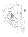
- la figure 5 représente une deuxième variante de réalisation de l'invention,
- les figures 6A à 6F sont des vues de la deuxième variante de réalisation, les ailettes étant dans différentes positions,
- la figure 7 représente une troisième variante de réalisation de l'invention, et
- la figure 8 représente une quatrième variante de réalisation de l'invention.
- FIG. 1 represents a sectional view of the barrel according to the invention, the fins being in the closed position,
- FIG. 2 is a side view in section of the barrel of FIG. 1 along the line II-II,
- FIG. 3 is a view similar to that of FIG. 1, the fins being in the open position,
- FIGS. 4A and 4B are views similar to FIG. 1 of a first alternative embodiment of the invention, the fins being respectively in the open position and in the closed position,
- FIG. 5 represents a second variant embodiment of the invention,
- FIGS. 6A to 6F are views of the second variant embodiment, the fins being in different positions,
- FIG. 7 represents a third alternative embodiment of the invention, and
- FIG. 8 represents a fourth alternative embodiment of the invention.
En référence aux figures 1 à 3, le barillet d'aérateur 1 selon l'invention comporte un
corps 2 creux monté dans l'habitacle d'un véhicule à la sortie d'un conduit d'air du
circuit de ventilation, un jeu d'ailettes directionnelles 3 pour défléchir le flux d'air
reliées entre elles par une barrette de liaison 4, et une molette de commande 5
accessible de l'habitacle par l'utilisateur pour faire varier à guise la position desdites
ailettes. Le corps 2 du barillet est fermé en face frontale par un capot d'aspect 6
laissant apparaítre la molette de commande 5 et les ailettes directionnelles 3.Referring to Figures 1 to 3, the
De manière connue, les ailettes directionnelles 3 sont disposées parallèles entre elles et
montées dans le corps 2 de manière pivotante autour d'axes de pivotement fixes A.
Elles sont disposées pour former un "rideau" c'est-à-dire qu'elles sont alignées de
manière à obturer totalement la sortie du flux d'air dans une de leurs positions
extrêmes représentée dans la figure 1. L'autre position extrême correspond à leur
position totalement ouverte représentée dans la figure 3. Ces deux positions extrêmes
sont décalées d'un angle β1 à β5 différent selon la position de chaque ailette 3, qui sont
par exemple au nombre de cinq, ce nombre pouvant varier de 1 à 10 par exemple. Ces
angles sont également représentés dans la figure 3 où la position fermée est illustrée
en traits interrompus.In known manner, the
Ces ailettes directionnelles 3 sont reliées entre elles par la barrette de liaison 4 en des
points de liaison B distants des axes de pivotement A pour créer un couple de
rotation. Cette barrette de liaison 4 est commandée par la molette de commande 5 qui
est montée en rotation dans ledit corps 2 autour d'un axe fixe C et entre deux parois
parallèles 2a, 2b dudit corps. La barrette de liaison 4 et la molette de commande 5
sont disposées de préférence dans deux plans sensiblement parallèles.These
La molette de commande 5 est couplée positivement à la barrette de liaison 4 par un
doigt de commande 7 solidaire de la molette 5 qui coulisse sur une came 8 solidaire de
la barrette de liaison 4. Bien entendu, l'inverse peut également être prévu, c'est-à-dire
le doigt de commande 7 peut être solidaire de la barrette de liaison 4 et la came 8 de
la molette de commande 5.The
Dans l'exemple de réalisation illustré, l'axe D du doigt de commande 7 est
sensiblement parallèle à l'axe C de rotation de la molette de commande 5 et distant de
cet axe d'un rayon R. Le doigt de commande 7 traverse ledit corps 2 par une rainure 9
présentant une forme en arc de cercle, de centre C, de rayon R et s'étendant sur un
secteur angulaire a qui peut être compris entre 10° et 130°. Les extrémités de cette
rainure 9 définissent les butées pour les deux positions extrêmes de la molette de
commande 7 qui correspondent aux deux positions extrêmes des ailettes
directionnelles 3, soit une position des ailettes totalement ouverte et une position des
ailettes totalement fermée.In the illustrated embodiment, the axis D of the
Dans l'exemple de réalisation illustré, la came 8 est constituée d'une rainure 10 de
forme gauche prévue dans un prolongement de la barrette de liaison 4. Cette came 8
peut être également constituée d'une rampe de forme gauche dans une variante de
réalisation. La rainure 10 a une section sensiblement égale au diamètre du doigt de
commande 7 pour permettre son coulissement avec un léger frottement. Cette rainure
10 s'étend sur une longueur au moins égale au trajet parcouru par le doigt de
commande 7 entre les deux positions extrêmes de la molette de commande 5. Elle a
une forme gauche courbe qui permet de faire correspondre les deux positions
extrêmes de la molette de commande 5 à celles des ailettes directionnelles 3. Et entre
ces deux positions extrêmes de la molette de commande 5, le doigt de commande 7
occupe dans la rainure 10 des positions intermédiaires qui correspondent aux
positions ouvertes intermédiaires des ailettes directionnelles 3. Ces positions ouvertes
intermédiaires sont stables étant donné que le doigt de commande 7 est retenu par
frottement dans la rainure 10.In the illustrated embodiment, the
Toutes les pièces formant ledit barillet d'aération 1 peuvent être réalisées dans une
matière synthétique injectée, en utilisant ou non un procédé de surmoulage.All the parts forming said
Le fonctionnement du barillet d'aérateur 1 selon l'invention est très simple. Quand les
ailettes directionnelles 3 sont en position fermée, elles empêchent la sortie du flux d'air
et jouent le rôle d'un volet d'obturation. Néanmoins, dans certaines réalisations, le
conduit d'air peut être équipé d'un volet intérieur d'obturation commandé par un levier
ou une molette indépendant. L'ouverture des ailettes directionnelles 3 est obtenue en
manoeuvrant la molette de commande 5 qui actionne directement la barrette de liaison
4 par l'intermédiaire du doigt de commande 7 et de la rainure 10. Grâce à cette liaison
directe, la rotation des ailettes directionnelles 3 a l'avantage d'être proportionnelle à
celle de la molette de commande 5 sur toute la course angulaire a. Ainsi on obtient
une meilleure gestion des différentes positions des ailettes directionnelles 3 et des
efforts de manoeuvre. The operation of the
Les figures 4A et 4B représentent un barillet d'aération 11 qui constitue une première
variante de réalisation du barillet d'aération 1 décrit précédemment. Toutes les pièces
identiques portent le même numéro de référence. Seule la came 18 est différente. La
rainure 20 de forme gauche qui la constitue comporte une zone de verrouillage 20' des
ailettes 3 en position fermée. Dans cette zone de verrouillage 20', la rainure 20
comporte un coude orientant la rainure 20 sensiblement en direction de l'axe C de
rotation de la molette 5. En position fermée (fig. 4B), le doigt de commande 7 se
trouve dans la zone de verrouillage 20' juste après le coude. Les ailettes
directionnelles 3 sont fermées et verrouillées dans cette position. En effet, elles ne
peuvent pas être déréglées ou déplacées sous l'effet d'une pression manuelle exercée
par l'utilisateur directement sur les ailettes car le doigt de commande 7 est bloqué dans
la zone de verrouillage 20' et ne peut pas remonter le coude prévu dans la rainure 20.
Seule la manoeuvre de la molette 5 permet de dégager le doigt de commande 7 de
cette zone de verrouillage 20' et d'ouvrir les ailettes 3.FIGS. 4A and 4B represent a
La figure 5 illustre un barillet d'aération 21 qui constitue une deuxième variante de
réalisation du barillet d'aération 1 décrit précédemment. Toutes les pièces identiques
portent le même numéro de référence. Dans cette variante, la came 28 est prévue dans
la molette 25 et est constituée d'une rainure 30 en forme de V ouvert dans laquelle
coulisse le doigt de commande 27 solidaire de la barrette de liaison 24. Au point le
plus bas de la rainure 30 est prévu un creux 30' agencé pour recevoir une dent
d'indexage 27' prévue sur le doigt de commande 27. Pour mieux comprendre le but
recherché par cette variante de réalisation, les figures 6A à 6F illustrent ce même
barillet d'aérateur 21 mais sans la dent d'indexage 27' ni le creux 30'. Dans le sens de
la flèche O, la molette de commande 25 entraíne l'ouverture des ailettes directionnelles
3 et inversement dans le sens de la flèche F. La figure 6A illustre les ailettes 3 en
position fermée, les figures 6B et 6C illustrent les ailettes 3 dans des positions
intermédiaires et la figure 6D illustre les ailettes 3 en position d'ouverture totale des
ailettes. Entre les positions illustrées par les figures 6B et 6C, on constate que la
molette de commande 25 peut effectuer une rotation angulaire X sans que cela
engendre un déplacement de la barrette de liaison 24 et une rotation des ailettes 3.
L'angle Y de rotation des ailettes 3 reste identique. Il existe alors une course dite
"morte" quel que soit le sens de rotation O ou F de la molette de commande 25.
D'autre part, dans la figure 6E, qui correspond à la figure 6B, il est possible de
déplacer manuellement la barrette de liaison 24 du point G au point H (figure 6F) sans
pour cela entraíner une rotation de la molette de commande 25. Lors de cette
manoeuvre, on inverse le sens normal de rotation des ailettes 3. La flèche I représente
le sens de rotation normale pour aller du point G au point H et la flèche J représente le
sens de rotation fausse des ailettes 3 pour aller du point G au point H. De ce fait, le
fonctionnement normal de la cinématique n'est plus respecté. La barrette de liaison 24
translatée au point H (figure 6F) par rapport à la molette de commande 25 engendre
le non fonctionnement de la cinématique de commande. La molette de commande 25
ne peut plus inverser la barrette de liaison 24 et, sous l'effet de cette résistance, elle
casse systématiquement.
Pour éviter ces inconvénients, le doigt de commande 27 a été complété par un doigt
d'indexage 27' et la rainure 30 de la came 28 par un creux 30', en référence aux figures
5 et 6G. Cette dent d'indexage 27' a pour effet d'assurer l'entraínement continuel de la
barrette de liaison 24 sous l'action de la rotation de la molette de commande 25. Ainsi,
la course "morte" est supprimée et les ailettes 3 ne peuvent pas effectuer la rotation
suivant la flèche J pour que la barrette de liaison 24 se translate du point G au point H
car la dent d'indexage 27' entre en interférence avec la came 28 de la molette de
commande 25.
La figure 7 illustre un barillet d'aération 31 qui constitue une troisième variante de
réalisation du barillet d'aération 1 décrit précédemment. Toutes les pièces identiques
portent le même numéro de référence. Dans cette variante, la barrette de liaison 34
comporte deux cames 38a et 38b situées de part et d'autre de l'axe C de rotation de la
molette de commande 5. Chaque came 38a, 38b coopère avec un doigt de commande
respectivement 37a et 37b prévu sur la molette 5. Les doigts 37a, 37b sont
diamétralement opposés par rapport à l'axe C de rotation de la molette de commande
5 et distants de cette axe du rayon R. Le doigt de commande 37a agit sur la came 38a
dans la direction de la flèche K pour l'ouverture des ailettes 3, dans le sens inverse de
la flèche F, et le doigt de commande 37b agit sur la came 38b dans la direction de la
flèche L pour la fermeture desdites ailettes 3, dans le sens de la flèche F. Les deux
cames 38a, 38b ont par conséquent des formes gauches différentes pour optimiser le
déplacement des ailettes 3. La barrette de liaison 34 présente, dans cette variante de
réalisation, une surface plus importante que dans les réalisations décrites plus haut et
les bras de liaison 34', 34" aux ailettes 3 supérieures sont très allongés et ont une
grande souplesse. Cette variante de réalisation est généralement utilisée pour des
courses importantes entre l'ouverture et la fermeture des ailettes dans le but de
maítriser le sens de rotation des ailettes. Dans une réalisation à une seule came, la
barrette de liaison du fait de sa longueur a tendance à s'arc-bouter, permettant la
rotation des ailettes en sens inverse. Avec la double came, cet inconvénient est
supprimé.FIG. 5 illustrates an
To avoid these drawbacks, the
FIG. 7 illustrates an
La figure 8 illustre un barillet d'aération 41 qui constitue une quatrième variante de
réalisation du barillet d'aération 1 décrit précédemment. Dans cette variante, seules les
ailettes 3 sont représentées dans le corps 2 du barillet. La distance entre les points de
pivotement A et B est différente pour chaque ailette 3. Ainsi on a r1 différent de r2
différent de r3 différent de r4 différent de r5. Les rayons n'étant pas identiques, pour
un déplacement de la barrette de liaison (non représentée), on obtient un déplacement
angulaire différent pour chaque ailette 3 et donc un angle d'ouverture entre chaque
ailette différent. Ainsi on a β1 différent de β2 différent de β3 différent de β4. On
obtient un effet éventail. Cette variante de réalisation peut être appliquée à chaque
mode de réalisation décrit précédemment et, notamment, à celui illustré par la figure 7
compte tenu de la souplesse de la barrette de liaison.FIG. 8 illustrates a
La présente invention n'est pas limitée aux exemples de réalisation décrits mais s'étend à toute modification et variante évidente pour un homme du métier. Notamment la forme des barrettes de liaison et celle des cames ne sont pas limitées. Les angles de manoeuvre et de déplacement des différentes pièces peuvent également variés en fonction des besoins. De même, la liaison directe entre la molette de commande et la barrette de liaison peut être appliquée à différents types et formes de barillet d'aérateur.The present invention is not limited to the embodiments described but extends any modification and variant obvious to a person skilled in the art. Especially the shape of the connecting bars and that of the cams are not limited. The angles of maneuvering and moving the different parts can also be varied according to needs. Similarly, the direct connection between the control wheel and the connecting bar can be applied to different types and shapes of barrel aerator.
Claims (12)
Applications Claiming Priority (2)
| Application Number | Priority Date | Filing Date | Title |
|---|---|---|---|
| FR9710113A FR2766765B1 (en) | 1997-08-04 | 1997-08-04 | AERATOR BARREL FOR A MOTOR VEHICLE |
| FR9710113 | 1997-08-04 |
Publications (2)
| Publication Number | Publication Date |
|---|---|
| EP0899136A1 true EP0899136A1 (en) | 1999-03-03 |
| EP0899136B1 EP0899136B1 (en) | 2002-04-10 |
Family
ID=9510111
Family Applications (1)
| Application Number | Title | Priority Date | Filing Date |
|---|---|---|---|
| EP19980440171 Expired - Lifetime EP0899136B1 (en) | 1997-08-04 | 1998-08-04 | Air diffuser for a motor vehicle |
Country Status (3)
| Country | Link |
|---|---|
| EP (1) | EP0899136B1 (en) |
| DE (1) | DE69804731T2 (en) |
| FR (1) | FR2766765B1 (en) |
Cited By (6)
| Publication number | Priority date | Publication date | Assignee | Title |
|---|---|---|---|---|
| EP1055536A1 (en) * | 1999-05-18 | 2000-11-29 | TRW Automotive Electronics & Components GmbH & Co. KG | System with vanes |
| WO2001008912A1 (en) * | 1999-07-28 | 2001-02-08 | Volkswagen Ag | Air vent with lamellae |
| EP1291209A3 (en) * | 2001-09-07 | 2004-04-14 | Nihon Plast Co., Ltd. | Ventilator |
| US6800023B2 (en) | 2001-01-16 | 2004-10-05 | Trw Automotive Electronics & Components Gmbh & Co. Kg | Air vent, especially for vehicle air-conditioning |
| AU2003245907B2 (en) * | 2002-06-03 | 2009-02-19 | Vrije Universiteit Brussel | Streptococcus thermophilus strain producing exopolysaccharide |
| US9073408B2 (en) | 2012-01-09 | 2015-07-07 | Ford Global Technologies, Llc | Register vane air deflector and method |
Families Citing this family (6)
| Publication number | Priority date | Publication date | Assignee | Title |
|---|---|---|---|---|
| FR2790426B1 (en) * | 1999-03-02 | 2001-05-04 | Coutier Moulage Gen Ind | AERATOR BARREL FOR MOTOR VEHICLE |
| DE10244280B4 (en) * | 2002-09-23 | 2013-05-02 | Volkswagen Ag | Ventilation device for a vehicle, in particular for a motor vehicle |
| DE10244327B4 (en) * | 2002-09-23 | 2011-01-13 | Volkswagen Ag | Ventilation device for a vehicle, in particular for a motor vehicle |
| DE102004004427B4 (en) * | 2004-01-28 | 2009-04-09 | Olho-Technik Oleff & Holtmann Ohg | exhaust nozzle |
| DE102010035079A1 (en) * | 2010-08-21 | 2012-02-23 | Volkswagen Ag | Air-outlet device for introducing air into inner space of vehicle, has air guidance slats connected to control disk and pivoted in rotational axis by rotation of control disk that is rotated in rotational axis by control element |
| FR3050149B1 (en) * | 2016-04-18 | 2018-04-06 | Reydel Automotive B.V. | ARRANGEMENT OF MOBILE FINES ESPECIALLY FOR AERATOR |
Citations (4)
| Publication number | Priority date | Publication date | Assignee | Title |
|---|---|---|---|---|
| US5072657A (en) * | 1989-02-28 | 1991-12-17 | Daikyo Co., Ltd. | Blowing louver with swinging fins for air conditioners |
| WO1994000310A1 (en) * | 1992-06-19 | 1994-01-06 | Dr. Franz Schneider Gmbh | Nozzle for ventilating or air conditioning installations, especially in motor vehicle interiors |
| EP0782939A2 (en) | 1996-01-04 | 1997-07-09 | AURORA Konrad G. Schulz GmbH & Co | Air nozzle |
| FR2760694A1 (en) * | 1997-03-12 | 1998-09-18 | Bourbon Automobile Sa | Outlet for directional control of fluid flow e.g. air-conditioning outlet for vehicle cabin |
-
1997
- 1997-08-04 FR FR9710113A patent/FR2766765B1/en not_active Expired - Fee Related
-
1998
- 1998-08-04 EP EP19980440171 patent/EP0899136B1/en not_active Expired - Lifetime
- 1998-08-04 DE DE1998604731 patent/DE69804731T2/en not_active Expired - Fee Related
Patent Citations (4)
| Publication number | Priority date | Publication date | Assignee | Title |
|---|---|---|---|---|
| US5072657A (en) * | 1989-02-28 | 1991-12-17 | Daikyo Co., Ltd. | Blowing louver with swinging fins for air conditioners |
| WO1994000310A1 (en) * | 1992-06-19 | 1994-01-06 | Dr. Franz Schneider Gmbh | Nozzle for ventilating or air conditioning installations, especially in motor vehicle interiors |
| EP0782939A2 (en) | 1996-01-04 | 1997-07-09 | AURORA Konrad G. Schulz GmbH & Co | Air nozzle |
| FR2760694A1 (en) * | 1997-03-12 | 1998-09-18 | Bourbon Automobile Sa | Outlet for directional control of fluid flow e.g. air-conditioning outlet for vehicle cabin |
Cited By (6)
| Publication number | Priority date | Publication date | Assignee | Title |
|---|---|---|---|---|
| EP1055536A1 (en) * | 1999-05-18 | 2000-11-29 | TRW Automotive Electronics & Components GmbH & Co. KG | System with vanes |
| WO2001008912A1 (en) * | 1999-07-28 | 2001-02-08 | Volkswagen Ag | Air vent with lamellae |
| US6800023B2 (en) | 2001-01-16 | 2004-10-05 | Trw Automotive Electronics & Components Gmbh & Co. Kg | Air vent, especially for vehicle air-conditioning |
| EP1291209A3 (en) * | 2001-09-07 | 2004-04-14 | Nihon Plast Co., Ltd. | Ventilator |
| AU2003245907B2 (en) * | 2002-06-03 | 2009-02-19 | Vrije Universiteit Brussel | Streptococcus thermophilus strain producing exopolysaccharide |
| US9073408B2 (en) | 2012-01-09 | 2015-07-07 | Ford Global Technologies, Llc | Register vane air deflector and method |
Also Published As
| Publication number | Publication date |
|---|---|
| FR2766765A1 (en) | 1999-02-05 |
| DE69804731T2 (en) | 2002-11-14 |
| EP0899136B1 (en) | 2002-04-10 |
| DE69804731D1 (en) | 2002-05-16 |
| FR2766765B1 (en) | 1999-10-01 |
Similar Documents
| Publication | Publication Date | Title |
|---|---|---|
| EP0899136B1 (en) | Air diffuser for a motor vehicle | |
| EP0986688B1 (en) | Improved articulation device for a hatchback mounted on a motor vehicle body | |
| FR2812612A1 (en) | Bicycle motorized front derailleur gear comprises fork unit for shifting chain and electric motor which controls activating arm through gearing | |
| LU83482A1 (en) | DEVICE FOR ADJUSTING THE RAISING OF VISORS OF HELMETS AND THE LIKE | |
| EP0125976B1 (en) | Flap valve system for the distribution of flow in an air conditioning unit for a motor vehicle | |
| EP1838541B1 (en) | Air nozzle for a motor vehicle, to be placed at the outlet of a vent pipe into the passenger compartment of the vehicle, and corresponding vehicle | |
| FR2558280A1 (en) | DEVICE FOR SIMULTANEOUSLY CONTROLLING TWO OSCILLATING PARTS SUCH AS SHUTTERS OF A MOTOR VEHICLE AIR CONDITIONING ASSEMBLY | |
| FR2809349A1 (en) | Ventilation outlet for motor vehicle interior has drum with rotary button driving main louvre via cable and vanes attached directly to vane operating console | |
| FR2790426A1 (en) | AERATOR BARREL FOR MOTOR VEHICLE | |
| FR3081384A1 (en) | AERATION DEVICE FOR ADJUSTING THE AIR FLOW AND VEHICLE THEREFOR | |
| FR2716141A1 (en) | Device for adjusting the folding shutters of a cylinder with folding shutters. | |
| EP1162095A1 (en) | Rotating hideaway aerator assembly for motor vehicle and its application system | |
| EP0007861B1 (en) | Adjusting device for a rear-view mirror, particularly for a vehicle | |
| FR2665479A1 (en) | DEVICE FOR OPERATING A PIVOTING SHUTTER ELEMENT. | |
| EP1410985A1 (en) | Pivoting steering wheel | |
| EP0009457B1 (en) | Bolt for a window, door or the like | |
| EP0704359B1 (en) | Windscreen wiper mechanism with non-circular wiping pattern | |
| FR2822108A1 (en) | Motor vehicle ventilation system housing has articulated trim panel linked to shutter | |
| FR2827815A1 (en) | Automobile ventilator comprises sealing joints located on shutter blade edge and body edge, and barrel with blades behind shutter blades controlled by rotating ring | |
| FR2768663A1 (en) | Air outlet especially for motor vehicle | |
| FR2667565A1 (en) | Pedal and bottom bracket assembly with cranks of fixed or variable length for cycles | |
| FR2717213A1 (en) | Improved device for hinging an opening, in particular a tailgate of a motor vehicle. | |
| EP1207259A2 (en) | Articulation device for an opening panel of a motor vehicle, especially for a tailgate | |
| FR2625543A1 (en) | Novel valve for pipelines | |
| FR2596100A1 (en) | Device for adjusting the slope of retractable arms for awnings blinds and the like |
Legal Events
| Date | Code | Title | Description |
|---|---|---|---|
| PUAI | Public reference made under article 153(3) epc to a published international application that has entered the european phase |
Free format text: ORIGINAL CODE: 0009012 |
|
| AK | Designated contracting states |
Kind code of ref document: A1 Designated state(s): DE FR IT |
|
| AX | Request for extension of the european patent |
Free format text: AL;LT;LV;MK;RO;SI |
|
| RIN1 | Information on inventor provided before grant (corrected) |
Inventor name: CAODURO, JEAN-PAUL |
|
| 17P | Request for examination filed |
Effective date: 19990830 |
|
| AKX | Designation fees paid |
Free format text: DE FR IT |
|
| GRAG | Despatch of communication of intention to grant |
Free format text: ORIGINAL CODE: EPIDOS AGRA |
|
| 17Q | First examination report despatched |
Effective date: 20010510 |
|
| GRAG | Despatch of communication of intention to grant |
Free format text: ORIGINAL CODE: EPIDOS AGRA |
|
| GRAH | Despatch of communication of intention to grant a patent |
Free format text: ORIGINAL CODE: EPIDOS IGRA |
|
| GRAH | Despatch of communication of intention to grant a patent |
Free format text: ORIGINAL CODE: EPIDOS IGRA |
|
| GRAA | (expected) grant |
Free format text: ORIGINAL CODE: 0009210 |
|
| AK | Designated contracting states |
Kind code of ref document: B1 Designated state(s): DE FR IT |
|
| PG25 | Lapsed in a contracting state [announced via postgrant information from national office to epo] |
Ref country code: IT Free format text: LAPSE BECAUSE OF FAILURE TO SUBMIT A TRANSLATION OF THE DESCRIPTION OR TO PAY THE FEE WITHIN THE PRE;WARNING: LAPSES OF ITALIAN PATENTS WITH EFFECTIVE DATE BEFORE 2007 MAY HAVE OCCURRED AT ANY TIME BEFORE 2007. THE CORRECT EFFECTIVE DATE MAY BE DIFFERENT FROM THE ONE RECORDED.SCRIBED TIME-LIMIT Effective date: 20020410 |
|
| REF | Corresponds to: |
Ref document number: 69804731 Country of ref document: DE Date of ref document: 20020516 |
|
| PLBE | No opposition filed within time limit |
Free format text: ORIGINAL CODE: 0009261 |
|
| STAA | Information on the status of an ep patent application or granted ep patent |
Free format text: STATUS: NO OPPOSITION FILED WITHIN TIME LIMIT |
|
| 26N | No opposition filed |
Effective date: 20030113 |
|
| PGFP | Annual fee paid to national office [announced via postgrant information from national office to epo] |
Ref country code: DE Payment date: 20030820 Year of fee payment: 6 |
|
| PG25 | Lapsed in a contracting state [announced via postgrant information from national office to epo] |
Ref country code: DE Free format text: LAPSE BECAUSE OF NON-PAYMENT OF DUE FEES Effective date: 20050301 |
|
| PGFP | Annual fee paid to national office [announced via postgrant information from national office to epo] |
Ref country code: FR Payment date: 20060731 Year of fee payment: 9 |
|
| REG | Reference to a national code |
Ref country code: FR Ref legal event code: ST Effective date: 20080430 |
|
| PG25 | Lapsed in a contracting state [announced via postgrant information from national office to epo] |
Ref country code: FR Free format text: LAPSE BECAUSE OF NON-PAYMENT OF DUE FEES Effective date: 20070831 |