EP4388284B1 - Tank- und sensoranordnung zur bestimmung eines flüssigkeitsstands für einen flugzeugtank, verfahren zur verwendung solch eines sensors - Google Patents
Tank- und sensoranordnung zur bestimmung eines flüssigkeitsstands für einen flugzeugtank, verfahren zur verwendung solch eines sensors Download PDFInfo
- Publication number
- EP4388284B1 EP4388284B1 EP22750724.1A EP22750724A EP4388284B1 EP 4388284 B1 EP4388284 B1 EP 4388284B1 EP 22750724 A EP22750724 A EP 22750724A EP 4388284 B1 EP4388284 B1 EP 4388284B1
- Authority
- EP
- European Patent Office
- Prior art keywords
- tank
- liquid
- pressure
- sensor
- measuring
- Prior art date
- Legal status (The legal status is an assumption and is not a legal conclusion. Google has not performed a legal analysis and makes no representation as to the accuracy of the status listed.)
- Active
Links
Images


Classifications
-
- G—PHYSICS
- G01—MEASURING; TESTING
- G01F—MEASURING VOLUME, VOLUME FLOW, MASS FLOW OR LIQUID LEVEL; METERING BY VOLUME
- G01F23/00—Indicating or measuring liquid level or level of fluent solid material, e.g. indicating in terms of volume or indicating by means of an alarm
- G01F23/14—Indicating or measuring liquid level or level of fluent solid material, e.g. indicating in terms of volume or indicating by means of an alarm by measurement of pressure
- G01F23/16—Indicating, recording, or alarm devices being actuated by mechanical or fluid means, e.g. using gas, mercury, or a diaphragm as transmitting element, or by a column of liquid
- G01F23/162—Indicating, recording, or alarm devices being actuated by mechanical or fluid means, e.g. using gas, mercury, or a diaphragm as transmitting element, or by a column of liquid by a liquid column
-
- F—MECHANICAL ENGINEERING; LIGHTING; HEATING; WEAPONS; BLASTING
- F01—MACHINES OR ENGINES IN GENERAL; ENGINE PLANTS IN GENERAL; STEAM ENGINES
- F01M—LUBRICATING OF MACHINES OR ENGINES IN GENERAL; LUBRICATING INTERNAL COMBUSTION ENGINES; CRANKCASE VENTILATING
- F01M11/00—Component parts, details or accessories, not provided for in, or of interest apart from, groups F01M1/00 - F01M9/00
- F01M11/10—Indicating devices; Other safety devices
- F01M11/12—Indicating devices; Other safety devices concerning lubricant level
-
- G—PHYSICS
- G01—MEASURING; TESTING
- G01F—MEASURING VOLUME, VOLUME FLOW, MASS FLOW OR LIQUID LEVEL; METERING BY VOLUME
- G01F22/00—Methods or apparatus for measuring volume of fluids or fluent solid material, not otherwise provided for
- G01F22/02—Methods or apparatus for measuring volume of fluids or fluent solid material, not otherwise provided for involving measurement of pressure
-
- G—PHYSICS
- G01—MEASURING; TESTING
- G01F—MEASURING VOLUME, VOLUME FLOW, MASS FLOW OR LIQUID LEVEL; METERING BY VOLUME
- G01F23/00—Indicating or measuring liquid level or level of fluent solid material, e.g. indicating in terms of volume or indicating by means of an alarm
- G01F23/0007—Indicating or measuring liquid level or level of fluent solid material, e.g. indicating in terms of volume or indicating by means of an alarm for discrete indicating and measuring
-
- G—PHYSICS
- G01—MEASURING; TESTING
- G01F—MEASURING VOLUME, VOLUME FLOW, MASS FLOW OR LIQUID LEVEL; METERING BY VOLUME
- G01F23/00—Indicating or measuring liquid level or level of fluent solid material, e.g. indicating in terms of volume or indicating by means of an alarm
- G01F23/14—Indicating or measuring liquid level or level of fluent solid material, e.g. indicating in terms of volume or indicating by means of an alarm by measurement of pressure
- G01F23/18—Indicating, recording or alarm devices actuated electrically
- G01F23/185—Indicating, recording or alarm devices actuated electrically for discrete levels
-
- B—PERFORMING OPERATIONS; TRANSPORTING
- B64—AIRCRAFT; AVIATION; COSMONAUTICS
- B64D—EQUIPMENT FOR FITTING IN OR TO AIRCRAFT; FLIGHT SUITS; PARACHUTES; ARRANGEMENT OR MOUNTING OF POWER PLANTS OR PROPULSION TRANSMISSIONS IN AIRCRAFT
- B64D1/00—Dropping, ejecting, releasing or receiving articles, liquids, or the like, in flight
- B64D1/16—Dropping or releasing powdered, liquid, or gaseous matter, e.g. for fire-fighting
Definitions
- the present invention relates to the field of measuring a liquid level in a tank of an aircraft, in particular, an oil tank of a helicopter.
- a submerged level sensor in an aircraft tank to measure a liquid level, for example, by measuring the position of a float of the level sensor in the tank.
- a submerged level sensor needs to adapt to the shape of the tank, which is a significant disadvantage given that tanks are generally of different shapes depending on the aircraft.
- a submerged level sensor has the disadvantage of being difficult to access, which penalizes maintenance.
- a tank comprises a liquid phase, the level of which is variable, and a complementary gas phase. It has been proposed to use a differential level sensor to determine the liquid level in a tank by measuring, on the one hand, the pressure of the liquid phase and, on the other hand, the pressure of the gas phase.
- a differential type level sensor 9 comprises a first tubing 91 in relation to the liquid phase PL and a second tubing 92 in relation to the gas phase PG of a tank 100.
- the level sensor 9 determines from the pressure difference a liquid level NL which is transmitted to a computer 6 of the aircraft in order to provide liquid level information to the propulsion system of the aircraft or to the pilot.
- Such tubings 91, 92 extend externally to the tank 91, 92, which increases the bulk.
- These problems are all the more significant since each tank 100 comprises several differential level sensors 9 in order to ensure consolidation of the level measurement and limit errors, in particular, linked to movements of the aircraft. During maintenance, it is necessary to remove the tubings 91, 92, which is complex and time-consuming.
- the invention thus aims to eliminate at least some of these drawbacks by proposing a liquid level determination sensor which adapts to any tank, the maintenance of which is simplified while having limited space requirements.
- the invention relates to an assembly according to claim 1.
- the invention advantageously provides a two-part sensor that allows the orifice to be conveniently closed to prevent any loss of liquid and/or pollution.
- a removable assembly allows for simple and rapid maintenance of the measuring element. It can thus be inspected and/or replaced without difficulty.
- the measuring device comprises an external pipe opening outside the tank to measure the external pressure as a reference pressure.
- the measuring device makes it possible to use the external pressure as a reference pressure. This makes it possible to form a sensor with reduced space requirements. It is therefore not necessary to provide a high opening in the tank.
- the measuring device comprises a gas line configured to be in fluid communication with a gas phase of the tank as a reference pressure.
- the gas line is connected to a filler cap of the tank, which makes it possible to avoid forming a dedicated orifice in the tank.
- the gas line is flexible so as to allow convenient manipulation of the filler cap with the gas line.
- the measuring device comprises two pressure measuring members in order to ensure redundancy and/or consolidation of the liquid level measurement.
- the assembly comprises a single sensor.
- the reservoir having a minimum liquid height designated "alert height"
- the orifice is positioned at a height lower than said alert height.
- the liquid line is always filled with liquid to provide liquid pressure.
- the orifice is a drain orifice of the tank in which a drain plug is mounted, the sensor is integrated into said drain plug.
- a measurement at the drain plug is very advantageous since the closure device performs a sealing function without requiring dedicated machining in the tank.
- the position of the drain plug in a very low position ensures that the liquid line will always be filled with liquid to provide liquid pressure.
- An integration of the sensor in the drain plug allows the application of the invention to aircraft tanks in circulation (backward compatibility), which is very advantageous.
- the reservoir comprises a mouth formed around the orifice, the mouth comprising at least one opening, in fluid communication with a gas phase of the reservoir via a first internal gas conduit portion, the closure device comprising a second internal gas conduit portion configured to supply the measuring member with the gas pressure.
- An internal gas line allows for a significant reduction in size, the closure device allowing the measuring device to be supplied with liquid pressure and gas pressure.
- the size is reduced as is the mass.
- the automatic closing member of the liquid line allows the liquid line and the second portion of the internal gas line to be closed when the measuring device is not mounted on the closure device.
- the assembly comprises at least one auxiliary pressure sensor configured to measure a liquid pressure at a determined height of the orifice so as to deduce a liquid density therefrom.
- the type of liquid can be deduced to determine a liquid level correction parameter.
- the liquid level supplied to the pilot is very precise.
- the invention further relates to an aircraft comprising a sensor as presented previously and/or an assembly of an aircraft tank and a sensor as presented previously.
- the method includes a step of issuing an alarm when the liquid pressure is equal to the reference pressure.
- the operator under extreme conditions (rapid descent/rise), the operator is informed that the level measurement is not reliable. He can thus control by taking into account only the other relevant measurements.
- the invention will be presented for an oil tank of a helicopter but it goes without saying that the invention applies to other types of tank (fuel, coolant, etc.) and other types of aircraft (airplane, etc.).
- a tank 100 of a helicopter is schematically represented.
- the tank 100 is represented in the form of a block but this is generally complex with a non-flat bottom.
- the tank 100 comprises a liquid phase PL, the level of which is variable, and a complementary gaseous phase PG.
- the interface between the two phases PL, PG corresponds to the liquid level NL to be determined.
- the tank 100 has a wall 102 having a thickness enabling it to withstand pressure, generally metallic.
- the tank 100 has at least one liquid inlet H1 and one liquid outlet H2 in order to supply a liquid circuit, in particular, an oil circuit for cooling components of an aircraft turbomachine.
- the tank 100 comprises a drain orifice 101 which is positioned in a low point of the tank 100 so as to allow its draining by gravity.
- a drain orifice 101 is formed during the manufacture of a tank 100 and advantageously does not require additional machining.
- the drain orifice 101 comprises a mouth, preferably cylindrical, to cooperate with a drain plug closing said drain orifice 101.
- a sensor 1 for determining a liquid level NL is integrated into said drain plug so that the latter advantageously fulfills a dual function and limits the size.
- the senor 1 could be used independently, in particular, in a fluid circulation orifice other than the drain orifice 101.
- the senor 1 is positioned at a height lower than a minimum liquid height designated “alert height” HA.
- the drain orifice 101 has a very low height and meets this condition.
- the sensor 1 is located in a position that is not very subject to turbulence due to the suction and discharge of liquid (proximity to the liquid inlet H1 and the liquid outlet H2).
- the drain orifice 101 is generally located opposite and meets this condition.
- the HA warning height advantageously takes this phenomenon into account.
- the senor 1 comprises a closing device 2, configured to be mounted in the drain orifice 101, and a measuring device 3, removably mounted on the closing device 2.
- the measuring device 3 forms a removable accessory which is not necessary to close the tank 100. Due to its removable nature, the maintenance of the measuring device 3 is greatly simplified.
- the closure device 2 comprises a liquid pipe 20 configured to conduct liquid from the drain orifice 101 and an automatic closure member 21 of the liquid pipe 20 if the measuring device 3 is not mounted on the closure device 2.
- the cooperation of the measuring device 3 with the closure device 2 makes it possible to inactivate the automatic closure member 21 and allows a circulation of liquid making it possible to measure the liquid pressure P2.
- the automatic closure member 21 can be in various forms, in particular, a non-return valve.
- the closing device 2 advantageously fulfills a plug function by blocking the drain orifice 101.
- the measuring device 3 makes it possible to measure the liquid level NL and can be replaced quickly in the event of a malfunction. This solution is advantageous since it can be transposed to any existing tank 100. In addition, in the event of maintenance or technological development of the measuring device 3, it can be replaced in a practical manner.
- the closing device 2 and the measuring device 3 are mounted together mechanically, for example, by screwing, by fitting, by a bayonet system or the like. It goes without saying that a magnetic mounting could also be suitable.
- the measuring member 30 is connected to a computer 6 of the aircraft in order to provide liquid level information to the propulsion system of the aircraft or to the pilot.
- the pressure measuring member 30 is in the form of an electronic chip configured to determine a pressure difference between the liquid pressure P1 and the reference pressure.
- the measuring device 3 comprises a single pressure measuring member 30.
- the measuring device 3 comprises an external pipe 31, opening outside the tank 100.
- the reference pressure is the external pressure Pext of the external environment Mext, that is to say, atmospheric pressure.
- the atmospheric pressure Pext forms a stable reference pressure which makes it possible to precisely determine the liquid level NL in a differential manner.
- the integration of a sensor 1 in a drain plug makes it possible to measure the liquid level NL without modifying the reservoir 100, which is advantageous.
- the space requirement is also limited.
- the measuring device 3 comprises a gas pipe 32 in fluid communication with the gas phase PG of the reservoir 100.
- the reference pressure Pref is the gas pressure P2, that is to say, the pressure of the gas phase PG.
- the gas line 32 extends externally to the tank 100 and connects the measuring member 30 to an upper opening 103 formed in the tank 100.
- the gas line 32 may be flexible or rigid.
- the gas line 32 is equipped with pneumatic connections at its ends.
- the gas line 32 opens into a filler cap (not shown) mounted in a filler orifice located in the upper part of the tank 100.
- a gas line 32 which is flexible makes it possible to avoid its disassembly when the tank 100 is filled. The filler cap can thus be handled while remaining connected to the gas line 32.
- the gas phase PG makes it possible to form a relevant comparison basis for determining the liquid level NL.
- the gas pipe 32' extends internally to the reservoir 100 and to the closure device 2 and makes it possible to connect a high orifice 104 (tapping) opening into the interior of the reservoir 100 and the measuring member 30 of the measuring device 3.
- the internal gas pipe 32' comprises a first portion 32a' which is formed in the thickness of the wall 102 of the reservoir 100 and a second portion 32b' which is formed in the closure device 2.
- the mouth 101 of the reservoir 100 comprises an opening which allows fluid communication between the two portions 32a', 32b'.
- seals are provided to ensure sealing, in particular, O-rings.
- the closing device 2 makes it possible to supply a liquid pressure P1 and a gas pressure P2 in a centralized and practical manner to the measuring device 3.
- the measuring member 30 thus makes it possible to deduce the liquid level NL.
- the first portion 32a' of the gas pipe 32' extends upwards from the upper orifice 104 and downwards from the opening which allows fluid communication between the two portions 32a', 32b, to avoid any phenomenon of accumulation of liquid mist in the gas pipe 32', which would distort the measurement.
- the measuring device 3 of the sensor 1 comprises two measuring members 30a, 30b in order to carry out independent level measurements NL1, NL2 which are supplied to the computer 6.
- the measuring members 30a, 30b are integrated into the same sensor 1 to reduce the size and the number of machining operations in the tank 100.
- each tank 100 is only associated with a single sensor 1, which may comprise one or more measuring members 30a, 30b. Due to the redundancy, it is no longer necessary to provide a window in the tank 100 in order to allow a visual check of the liquid level NL.
- the two measuring members 30a, 30b each make it possible to measure a fluid pressure P1 and an external pressure Pext.
- the two measuring members 30a, 30b are supplied separately in order to guarantee the independence of the measurements. Nevertheless, it goes without saying that communication with the liquid phase PL or the external environment Mext could be common in order to limit the size.
- the two measuring members 30a, 30b each make it possible to measure a fluid pressure P1 and a gas pressure P2.
- the two measuring members 30a, 30b are supplied separately in order to guarantee the independence of the measurements. Nevertheless, it goes without saying that communication with the liquid phase PL or the gas phase PG could be common in order to limit the size.
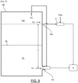
- the first measuring member 30a makes it possible to measure a fluid pressure P1 and a gas pressure P2 while the second measuring member 30b makes it possible to measure a fluid pressure P1 and an external pressure Pext.
- the use of two reference pressures of different natures makes it possible to obtain two level measurements NL1, NL2 which are independent and decorrelated. This makes it possible to detect a drift of one of the measuring members 30a, 30b or another fault in a practical manner. Indeed, when the turbomachine is stopped, the pressures P2 and Pext must be identical and lead to the same liquid level measurement NL1, NL2.
- the calculator 6 can thus consolidate the measurements of level NL1, NL2 (average, etc.) in order to provide qualitative information to the aircraft propulsion system or to the pilot.
- the density of the liquid (here the oil density) is also determined. This information is important since the same turbomachine can be used with oils of different types. By knowing the type of oil, a correction parameter ⁇ NL1 for the NL level measurement can be determined and thus the measurement accuracy improved.
- an auxiliary pressure sensor 4 is placed in fluid communication with the liquid phase via an upper opening 104 of the reservoir 100 and with the external environment Mext having an external pressure Pext in order to carry out a differential pressure measurement which is supplied to the computer 6.
- the density measurement ⁇ is carried out after filling the tank 100.
- the density measurement ⁇ is stored in the computer 6 and will be used to determine the correction parameter ⁇ NL1 of the level measurement NL. It goes without saying that the density measurement ⁇ could be determined more frequently.
- the measuring device 3 comprises an amplification member, in particular a hydraulic one, in order to increase its sensitivity to the liquid pressure P1 and to accurately measure any variation.
- the amplification member is in the form of a piston rod whose ends have different sections so as to amplify the variations.
- the closing device 2 comprises a strainer in order to filter impurities in the liquid, in particular, in the automatic closing member. 21.
- the invention also relates to a method of using a sensor 1 mounted in a drain orifice 101 of an aircraft tank 100.
- the method of use will be presented in relation to the embodiment of the [ Fig. 5 ].
- the closing device 2 in the initial position, only the closing device 2 is mounted in the drain orifice 101.
- the closing member 21 is active and prevents any flow of liquid. If emptying is desired, an operator can insert a pipe into the closing member 21 or act on the control lever 22.
- the operator mounts the measuring device 3 on the closing device 2, which puts the measuring member 30 into fluid communication with the liquid pipe 20 which has a liquid pressure P1.
- the pressure measuring member 30 is also in fluid communication with the gas phase PG which has a gas pressure P2.
- the closing device 2 directly allows this fluid communication.
- the method comprises a step of determining the liquid level NL from the liquid pressure P1 and the gas pressure P2 measured by the measuring member 30. Such a differential measurement is robust.
- liquid level measurement can be conveniently implemented on any type of tank 100.
- the two-part structure of the sensor 1 allows for draining when necessary while facilitating maintenance since the measuring device 3 can be removed in a removable manner.
- the invention also relates to a method for detecting operating conditions from the sensor 1 according to the invention, in particular, extreme conditions such as a rapid climb/descent of the aircraft (abrupt change of altitude).
- the liquid housed in the tank 100 is subjected to the forces of gravity, which modifies the pressures measured by the sensor 1.
- the method comprises a step of issuing an alarm which is provided with the liquid level measurement NL or replaces it in order to inform the propulsion system or the pilot of the aircraft that the liquid level measurement NL is not reliable given the exceptional conditions.
- advantage is taken of the differential measurement for check the operating conditions and deduce an index of relevance of the NL liquid level measurement which is provided.
Landscapes
- Physics & Mathematics (AREA)
- Fluid Mechanics (AREA)
- General Physics & Mathematics (AREA)
- Engineering & Computer Science (AREA)
- Mechanical Engineering (AREA)
- General Engineering & Computer Science (AREA)
- Measuring Fluid Pressure (AREA)
- Measurement Of Levels Of Liquids Or Fluent Solid Materials (AREA)
Claims (9)
- Anordnung aus einem Flugzeugtank (100) und einem Sensor (1) zur Bestimmung eines Flüssigkeitsstands (NL) für einen Tank (100) eines Flugzeugs, wobei der Sensor (1) umfasst:- eine Verschlussvorrichtung (2), die in einer Öffnung (101) des Tanks (100) angebracht ist, die die Zirkulation von Flüssigkeit ermöglicht, und eine Messvorrichtung (3), die abnehmbar an der Verschlussvorrichtung (2) angebracht ist,- wobei die Verschlussvorrichtung (2) eine Flüssigkeitsleitung (20), die ausgelegt ist, um Flüssigkeit aus der Öffnung (100) des Tanks (100) zu leiten, und ein Organ (21) zum automatischen Verschließen der Flüssigkeitsleitung (20) umfasst, wenn die Messvorrichtung (3) nicht an der Verschlussvorrichtung (2) angebracht ist,- wobei die Messvorrichtung (3) mindestens ein Druckmessorgan (30) umfasst, das ausgelegt ist, um eine Druckdifferenz zwischen einerseits einem Flüssigkeitsdruck (P1) in der Flüssigkeitsleitung (20) und andererseits einem Referenzdruck (P2, Pext) zu messen, so dass daraus der Flüssigkeitsstand (NL) im Tank (100) abgeleitet wird,- wobei der Tank (100) eine um die Öffnung (101) herum gebildete Mündung umfasst, wobei die Mündung mindestens eine Öffnung in Fluidverbindung über einen ersten internen Gasleitungsabschnitt (32a') mit einer Gasphase (PG) des Tanks (100) aufweist, die in einer Dicke einer Wand (102) des Tanks (100) ausgebildet ist, wobei die Verschlussvorrichtung (2) einen zweiten internen Gasleitungsabschnitt (32b') aufweist, der ausgelegt ist, um das Messorgan (30) mit dem Gasdruck (P2) der Gasphase (PG) des Tanks (100) als Referenzdruck zu versorgen.
- Anordnung nach Anspruch 1, wobei die Messvorrichtung (3) eine äußere Leitung (31) aufweist, die aus dem Tank (100) ausmündet, um den Außendruck (Pext) als Referenzdruck zu messen.
- Anordnung nach einem der Ansprüche 1 bis 2, wobei die Messvorrichtung (3) zwei Druckmessorgane (30a, 30b) umfasst.
- Anordnung nach einem der Ansprüche 1 bis 3, wobei der Tank (100) eine als "Alarmhöhe (HA)" bezeichnete Mindestflüssigkeitshöhe aufweist, wobei die Öffnung (101) in einer Höhe unterhalb der Alarmhöhe (HA) positioniert ist.
- Anordnung nach einem der Ansprüche 1 bis 4, wobei die Öffnung eine Entleerungsöffnung (101) des Tanks (100) ist, in der ein Entleerungsstopfen angebracht ist, wobei der Sensor (1) in den Entleerungsstopfen integriert ist.
- Anordnung nach einem der Ansprüche 1 bis 6, die mindestens einen Hilfsdrucksensor (4) umfasst, der ausgelegt ist, um einen Flüssigkeitsdruck (P3) in einer bestimmten Höhe (h) der Öffnung (101) zu messen, um daraus eine Flüssigkeitsdichte (ρ) abzuleiten.
- Flugzeug, das eine Anordnung nach einem der Ansprüche 1 bis 6 aufweist.
- Verfahren zur Verwendung einer Anordnung aus einem Sensor (1) und einem Tank (100) eines Flugzeugs nach einem der Ansprüche 1 bis 6, wobei die Verschlussvorrichtung (2) des Sensors (1) in der Öffnung (101) des Tanks (100) angebracht ist, wobei das Verschlussorgan (21) die Flüssigkeitsleitung (20) verschließt, wobei das Verfahren Schritte umfasst, die darin bestehen:- Anbringen der Messvorrichtung (3) an der Verschlussvorrichtung (2), so dass das Messorgan (30) in Fluidverbindung mit dem Flüssigkeitsdruck (P1) gebracht wird, wobei das Verschlussorgan (21) nach der Anbringung inaktiviert ist,- Messen einer Druckdifferenz zwischen dem Flüssigkeitsdruck (P1) in der Flüssigkeitsleitung (20) einerseits und einem Referenzdruck (P2, Pext) andererseits, um daraus den Flüssigkeitsstand (NL) im Tank (100) abzuleiten.
- Verfahren zur Verwendung nach Anspruch 8, das einen Schritt des Sendens eines Alarms umfasst, wenn der Flüssigkeitsdruck (P1) gleich dem Referenzdruck (P2, Pext) ist.
Applications Claiming Priority (2)
| Application Number | Priority Date | Filing Date | Title |
|---|---|---|---|
| FR2108730A FR3126244B1 (fr) | 2021-08-17 | 2021-08-17 | Capteur de détermination d’un niveau de liquide pour un réservoir d’aéronef, ensemble d’un réservoir et d’un capteur, procédé d’utilisation d’un tel capteur |
| PCT/EP2022/071023 WO2023020797A1 (fr) | 2021-08-17 | 2022-07-27 | Capteur de détermination d'un niveau de liquide pour un réservoir d'aéronef, ensemble d'un réservoir et d'un capteur, procédé d'utilisation d'un tel capteur |
Publications (2)
| Publication Number | Publication Date |
|---|---|
| EP4388284A1 EP4388284A1 (de) | 2024-06-26 |
| EP4388284B1 true EP4388284B1 (de) | 2025-03-19 |
Family
ID=78536337
Family Applications (1)
| Application Number | Title | Priority Date | Filing Date |
|---|---|---|---|
| EP22750724.1A Active EP4388284B1 (de) | 2021-08-17 | 2022-07-27 | Tank- und sensoranordnung zur bestimmung eines flüssigkeitsstands für einen flugzeugtank, verfahren zur verwendung solch eines sensors |
Country Status (4)
| Country | Link |
|---|---|
| US (1) | US20240353250A1 (de) |
| EP (1) | EP4388284B1 (de) |
| FR (1) | FR3126244B1 (de) |
| WO (1) | WO2023020797A1 (de) |
Families Citing this family (13)
| Publication number | Priority date | Publication date | Assignee | Title |
|---|---|---|---|---|
| CA3212048A1 (en) | 2019-05-30 | 2020-11-30 | Marathon Petroleum Company Lp | Methods and systems for minimizing nox and co emissions in natural draft heaters |
| CA3109606C (en) | 2020-02-19 | 2022-12-06 | Marathon Petroleum Company Lp | Low sulfur fuel oil blends for paraffinic resid stability and associated methods |
| US11898109B2 (en) | 2021-02-25 | 2024-02-13 | Marathon Petroleum Company Lp | Assemblies and methods for enhancing control of hydrotreating and fluid catalytic cracking (FCC) processes using spectroscopic analyzers |
| US12473500B2 (en) | 2021-02-25 | 2025-11-18 | Marathon Petroleum Company Lp | Assemblies and methods for enhancing control of fluid catalytic cracking (FCC) processes using spectroscopic analyzers |
| US20250012744A1 (en) | 2021-02-25 | 2025-01-09 | Marathon Petroleum Company Lp | Methods and assemblies for enhancing control of refining processes using spectroscopic analyzers |
| US12461022B2 (en) | 2021-02-25 | 2025-11-04 | Marathon Petroleum Company Lp | Methods and assemblies for determining and using standardized spectral responses for calibration of spectroscopic analyzers |
| US11692141B2 (en) | 2021-10-10 | 2023-07-04 | Marathon Petroleum Company Lp | Methods and systems for enhancing processing of hydrocarbons in a fluid catalytic cracking unit using a renewable additive |
| US11802257B2 (en) | 2022-01-31 | 2023-10-31 | Marathon Petroleum Company Lp | Systems and methods for reducing rendered fats pour point |
| US12311305B2 (en) | 2022-12-08 | 2025-05-27 | Marathon Petroleum Company Lp | Removable flue gas strainer and associated methods |
| CA3238046A1 (en) | 2023-05-12 | 2025-07-07 | Marathon Petroleum Company Lp | Systems, apparatuses, and methods for sample cylinder inspection, pressurization, and sample disposal |
| US12533615B2 (en) | 2023-06-02 | 2026-01-27 | Marathon Petroleum Company Lp | Methods and systems for reducing contaminants in a feed stream |
| US12415962B2 (en) | 2023-11-10 | 2025-09-16 | Marathon Petroleum Company Lp | Systems and methods for producing aviation fuel |
| US12599848B2 (en) | 2024-06-03 | 2026-04-14 | Marathon Petroleum Company Lp | Systems, analyzers, controllers, and associated methods to enhance fluid separation for distillation operations |
Family Cites Families (42)
| Publication number | Priority date | Publication date | Assignee | Title |
|---|---|---|---|---|
| US4377809A (en) * | 1981-04-27 | 1983-03-22 | Itt | Liquid level system |
| DE3514911A1 (de) * | 1985-04-25 | 1986-10-30 | Pfister Gmbh, 8900 Augsburg | Druckmesseinrichtung |
| DE3928679A1 (de) * | 1989-08-30 | 1991-03-14 | Datacontrol Systemtechnik Gmbh | Verfahren und vorrichtung zur leckpruefung an vertikaltanks oder tankfarmen |
| US5606513A (en) * | 1993-09-20 | 1997-02-25 | Rosemount Inc. | Transmitter having input for receiving a process variable from a remote sensor |
| US5604315A (en) * | 1995-01-12 | 1997-02-18 | Setra Systems, Inc. | Apparatus using a feedback network to measure fluid pressures |
| DE19653879A1 (de) * | 1996-12-21 | 1998-06-25 | Mannesmann Vdo Ag | Füllstandsgrenzgeber und Verfahren zur Ermittlung eines Unter- oder Überschreitens einer vorgesehenen Füllhöhe von Flüssigkeit in einem Behälter |
| US5811690A (en) * | 1997-03-20 | 1998-09-22 | Hershey; George E. | Differential pressure transmitter with highly accurate temperature compensation |
| US6425293B1 (en) * | 1999-03-13 | 2002-07-30 | Textron Systems Corporation | Sensor plug |
| US6434494B1 (en) * | 1999-03-30 | 2002-08-13 | Simmonds Precision Products, Inc. | Pressure based fluid gauging system |
| US6571624B1 (en) * | 2001-12-03 | 2003-06-03 | The Boeing Company | Low gravity liquid level sensor rake |
| US7258130B2 (en) * | 2002-01-15 | 2007-08-21 | Adel Wiggins Group | Integrated jet fluid level shutoff sensor and fuel tank vent for vehicles |
| US6837262B2 (en) * | 2002-01-15 | 2005-01-04 | Adel Wiggins Group | Non tank pressurizing fast fill receiver and system for vehicles |
| US7270174B2 (en) * | 2003-12-16 | 2007-09-18 | International Business Machines Corporation | Method, system and program product for automatically checking coolant loops of a cooling system for a computing environment |
| US6889547B1 (en) * | 2003-12-19 | 2005-05-10 | Taylor Innovations, Llc | Liquid level input assembly for measuring the height of a column of liquid |
| US7032449B2 (en) * | 2004-07-14 | 2006-04-25 | Intevep, S.A. | Measurement of fluid properties in vessel and sensor for same |
| US6932028B1 (en) * | 2004-10-06 | 2005-08-23 | Vogt Power International Inc. | Apparatus and method for determining a liquid level in a steam drum |
| KR100882479B1 (ko) * | 2004-10-07 | 2009-02-06 | 엘지전자 주식회사 | 감온식 수위감지장치 및 이를 구비한 유체탱크 |
| EP1883792A4 (de) * | 2005-05-11 | 2009-07-08 | Innovative Solutions & Support | System und verfahren zur überwachung der flugzeugtreibstoffkapazität auf druckbasis |
| US8464590B2 (en) * | 2010-09-17 | 2013-06-18 | Cameron International Corporation | Pressure sensor configuration for pressurized tank |
| WO2013052667A1 (en) * | 2011-10-04 | 2013-04-11 | Spillx Llc | Refilling apparatus with jet level sensor |
| US8925382B1 (en) * | 2012-03-09 | 2015-01-06 | Kevin Beal | System and process for measuring a volume of a liquid within a keg |
| US9581483B2 (en) * | 2012-03-23 | 2017-02-28 | Honeywell International, Inc. | Tank overflow protection system and method |
| US9121743B2 (en) * | 2012-05-31 | 2015-09-01 | Rosemount Inc. | Process variable transmitter system with analog communication |
| US9194734B2 (en) * | 2012-07-09 | 2015-11-24 | United Technologies Corporation | Liquid level sensor system |
| GB201214969D0 (en) * | 2012-08-22 | 2012-10-03 | Airbus Uk Ltd | Fuel quantity measurement |
| US9458006B2 (en) * | 2013-03-15 | 2016-10-04 | Adel Wiggins Group | Non-pressurized fluid level shutoff for fuel tank |
| US11988539B2 (en) * | 2013-10-09 | 2024-05-21 | Parker-Hannifin Corporation | Aircraft fluid gauging techniques using pressure measurements and optical sensors |
| US20160054164A1 (en) * | 2014-08-19 | 2016-02-25 | Honeywell International Inc. | Compensated fluid level transmitter |
| US9494457B2 (en) * | 2014-12-05 | 2016-11-15 | Cub Elecparts Inc. | Tank liquid depth measurement method using a pressure sensor |
| US10830627B2 (en) * | 2015-04-15 | 2020-11-10 | Schlumberger Norge As | Method and system for fluid level determination from pressure measurement |
| US20170097254A1 (en) * | 2015-10-01 | 2017-04-06 | Numerex Corp. | Closed Tank Fill Level Sensor |
| US11933654B2 (en) * | 2016-06-14 | 2024-03-19 | Watgrid, S.A. | Level and/or density sensor device for liquid vessels |
| GB201705039D0 (en) * | 2017-03-29 | 2017-05-10 | Weston Aerospace Ltd | A Liquid level monitoring system |
| US10724891B2 (en) * | 2018-04-17 | 2020-07-28 | Hall Labs Llc | Apparatus and method for measuring level |
| BE1026218B1 (fr) * | 2018-04-19 | 2019-11-21 | Safran Aero Boosters S.A. | Dispositif de mesure de niveau pour réservoir d'huile de turbomachine |
| US20210356310A1 (en) * | 2018-04-30 | 2021-11-18 | Hewlett-Packard Development Company, L.P. | Particulate height calculations from pressure gradients |
| FR3086699B1 (fr) * | 2018-09-28 | 2020-11-13 | Safran Aircraft Engines | Procede de determination de la quantite d'huile d'un reservoir d'huile d'une turbomachine et ensemble de determination d'une telle quantite |
| US10914521B2 (en) * | 2019-01-24 | 2021-02-09 | Versum Materials Us, Llc | System and method for drying and analytical testing of containers |
| IL273837B (en) * | 2020-04-06 | 2021-01-31 | Hayman Meir | Device and method for measuring liquid level in a tank by a protected pressure sensor |
| US20230294838A1 (en) * | 2022-03-18 | 2023-09-21 | Eaton Intelligent Power Limited | Non-contact aircraft fuel tank gauging system and method |
| GB2630358A (en) * | 2023-05-25 | 2024-11-27 | Airbus Operations Ltd | Fuel tank monitoring system |
| GB2632125A (en) * | 2023-07-24 | 2025-01-29 | Airbus Operations Ltd | Fuel system |
-
2021
- 2021-08-17 FR FR2108730A patent/FR3126244B1/fr active Active
-
2022
- 2022-07-27 EP EP22750724.1A patent/EP4388284B1/de active Active
- 2022-07-27 US US18/683,606 patent/US20240353250A1/en active Pending
- 2022-07-27 WO PCT/EP2022/071023 patent/WO2023020797A1/fr not_active Ceased
Also Published As
| Publication number | Publication date |
|---|---|
| US20240353250A1 (en) | 2024-10-24 |
| FR3126244A1 (fr) | 2023-02-24 |
| EP4388284A1 (de) | 2024-06-26 |
| WO2023020797A1 (fr) | 2023-02-23 |
| FR3126244B1 (fr) | 2023-12-29 |
Similar Documents
| Publication | Publication Date | Title |
|---|---|---|
| WO2023020797A1 (fr) | Capteur de détermination d'un niveau de liquide pour un réservoir d'aéronef, ensemble d'un réservoir et d'un capteur, procédé d'utilisation d'un tel capteur | |
| EP0395200A1 (de) | Verfahren und Anordnung zur Ermittlung des Dampfdruckes einer Flüssigkeit | |
| CA2548900C (fr) | Procede et systeme d'evaluation de l'etancheite d'un dispositif de stockage de gaz carburant sous haute pression | |
| EP2626616B1 (de) | Dränagekreislauf einer Flüssigkeit, die aus einer Motorenanlage eines Drehflügelflugzeugs stammt, mit einem Überwachungsgerät für den übermäßigen Austritt der Flüssigkeit | |
| FR3019300A1 (fr) | Banc d'essai, destine a la caracterisation d'un ecoulement d'un fluide diphasique. | |
| EP0109883B1 (de) | Vorrichtung zur Kontrolle des Regeldrucks eines Sicherheitsventils | |
| CA2255201C (fr) | Methode et dispositif de debitmetrie polyphasique | |
| EP1963795A1 (de) | Verfahren und vorrichtung zur automatischen messung des ölverbrauchs eines verbrennungsmotors und zum austauschen des öls dieses motors | |
| EP2558700B1 (de) | Verfahren und vorrichtung zur formulierung eines sollwertsignals | |
| FR2777878A1 (fr) | Procede de recuperation de vapeurs emises au cours d'une distribution de liquide | |
| EP0088026B1 (de) | Kopf zur Niveaudetektion durch hydrostatischen Effekt mit Schutzvorrichtung | |
| EP2499370B1 (de) | Vorrichtung zur überwachung von probenentnahme mit einer kolbenpumpe | |
| EP3892833B1 (de) | Turbomaschine mit öltank, der mit sensoren versehen ist | |
| EP0022394B1 (de) | Verfahren und Vorrichtung zur Kontrolle der Entgasung eines Hydrauliksystems | |
| FR2510750A1 (fr) | Procede et dispositif de controle et d'ajustement d'une quantite de liquide contenue dans un reservoir | |
| EP0076178A2 (de) | Verfahren und Vorrichtung zur Prüfung von montierten Vergasern | |
| EP0349374A1 (de) | Verfahren und Vorrichtung zur Ermittlung einer Pumpeigenschaft oder eines Parameters eines Fluids | |
| FR3086699A1 (fr) | Procede de determination de la quantite d'huile d'un reservoir d'huile d'une turbomachine et ensemble de determination d'une telle quantite | |
| FR2858056A1 (fr) | Dispositif et procede de mesure de la quantite d'air dans une huile hydraulique | |
| CN223565326U (zh) | 一种管线加油车的车载测水装置 | |
| EP2207017B1 (de) | Volumetrisches Messgerät mit zwei Kolben für eine Kraftstoff-Abgabevorrichtung | |
| FR2522066A1 (fr) | Dispositif de maintien du niveau d'huile dans un moteur | |
| FR3147365A1 (fr) | Mesure de perméabilité d’un système d’injection de turbomachine | |
| FR3069054B1 (fr) | Jauge pour un liquide, notamment un hydrocarbure | |
| FR2608717A1 (fr) | Dispositif thermodoseur de fluides |
Legal Events
| Date | Code | Title | Description |
|---|---|---|---|
| STAA | Information on the status of an ep patent application or granted ep patent |
Free format text: STATUS: UNKNOWN |
|
| STAA | Information on the status of an ep patent application or granted ep patent |
Free format text: STATUS: THE INTERNATIONAL PUBLICATION HAS BEEN MADE |
|
| PUAI | Public reference made under article 153(3) epc to a published international application that has entered the european phase |
Free format text: ORIGINAL CODE: 0009012 |
|
| STAA | Information on the status of an ep patent application or granted ep patent |
Free format text: STATUS: REQUEST FOR EXAMINATION WAS MADE |
|
| 17P | Request for examination filed |
Effective date: 20240215 |
|
| AK | Designated contracting states |
Kind code of ref document: A1 Designated state(s): AL AT BE BG CH CY CZ DE DK EE ES FI FR GB GR HR HU IE IS IT LI LT LU LV MC MK MT NL NO PL PT RO RS SE SI SK SM TR |
|
| DAV | Request for validation of the european patent (deleted) | ||
| DAX | Request for extension of the european patent (deleted) | ||
| GRAP | Despatch of communication of intention to grant a patent |
Free format text: ORIGINAL CODE: EPIDOSNIGR1 |
|
| STAA | Information on the status of an ep patent application or granted ep patent |
Free format text: STATUS: GRANT OF PATENT IS INTENDED |
|
| INTG | Intention to grant announced |
Effective date: 20241203 |
|
| GRAS | Grant fee paid |
Free format text: ORIGINAL CODE: EPIDOSNIGR3 |
|
| GRAA | (expected) grant |
Free format text: ORIGINAL CODE: 0009210 |
|
| STAA | Information on the status of an ep patent application or granted ep patent |
Free format text: STATUS: THE PATENT HAS BEEN GRANTED |
|
| AK | Designated contracting states |
Kind code of ref document: B1 Designated state(s): AL AT BE BG CH CY CZ DE DK EE ES FI FR GB GR HR HU IE IS IT LI LT LU LV MC MK MT NL NO PL PT RO RS SE SI SK SM TR |
|
| REG | Reference to a national code |
Ref country code: GB Ref legal event code: FG4D Free format text: NOT ENGLISH |
|
| REG | Reference to a national code |
Ref country code: CH Ref legal event code: EP |
|
| REG | Reference to a national code |
Ref country code: DE Ref legal event code: R096 Ref document number: 602022012043 Country of ref document: DE |
|
| REG | Reference to a national code |
Ref country code: IE Ref legal event code: FG4D Free format text: LANGUAGE OF EP DOCUMENT: FRENCH |
|
| PG25 | Lapsed in a contracting state [announced via postgrant information from national office to epo] |
Ref country code: RS Free format text: LAPSE BECAUSE OF FAILURE TO SUBMIT A TRANSLATION OF THE DESCRIPTION OR TO PAY THE FEE WITHIN THE PRESCRIBED TIME-LIMIT Effective date: 20250619 |
|
| PG25 | Lapsed in a contracting state [announced via postgrant information from national office to epo] |
Ref country code: FI Free format text: LAPSE BECAUSE OF FAILURE TO SUBMIT A TRANSLATION OF THE DESCRIPTION OR TO PAY THE FEE WITHIN THE PRESCRIBED TIME-LIMIT Effective date: 20250319 |
|
| REG | Reference to a national code |
Ref country code: LT Ref legal event code: MG9D |
|
| PG25 | Lapsed in a contracting state [announced via postgrant information from national office to epo] |
Ref country code: NO Free format text: LAPSE BECAUSE OF FAILURE TO SUBMIT A TRANSLATION OF THE DESCRIPTION OR TO PAY THE FEE WITHIN THE PRESCRIBED TIME-LIMIT Effective date: 20250619 |
|
| PG25 | Lapsed in a contracting state [announced via postgrant information from national office to epo] |
Ref country code: HR Free format text: LAPSE BECAUSE OF FAILURE TO SUBMIT A TRANSLATION OF THE DESCRIPTION OR TO PAY THE FEE WITHIN THE PRESCRIBED TIME-LIMIT Effective date: 20250319 |
|
| PG25 | Lapsed in a contracting state [announced via postgrant information from national office to epo] |
Ref country code: LV Free format text: LAPSE BECAUSE OF FAILURE TO SUBMIT A TRANSLATION OF THE DESCRIPTION OR TO PAY THE FEE WITHIN THE PRESCRIBED TIME-LIMIT Effective date: 20250319 |
|
| PG25 | Lapsed in a contracting state [announced via postgrant information from national office to epo] |
Ref country code: BG Free format text: LAPSE BECAUSE OF FAILURE TO SUBMIT A TRANSLATION OF THE DESCRIPTION OR TO PAY THE FEE WITHIN THE PRESCRIBED TIME-LIMIT Effective date: 20250319 Ref country code: GR Free format text: LAPSE BECAUSE OF FAILURE TO SUBMIT A TRANSLATION OF THE DESCRIPTION OR TO PAY THE FEE WITHIN THE PRESCRIBED TIME-LIMIT Effective date: 20250620 |
|
| REG | Reference to a national code |
Ref country code: NL Ref legal event code: MP Effective date: 20250319 |
|
| PG25 | Lapsed in a contracting state [announced via postgrant information from national office to epo] |
Ref country code: NL Free format text: LAPSE BECAUSE OF FAILURE TO SUBMIT A TRANSLATION OF THE DESCRIPTION OR TO PAY THE FEE WITHIN THE PRESCRIBED TIME-LIMIT Effective date: 20250319 |
|
| PG25 | Lapsed in a contracting state [announced via postgrant information from national office to epo] |
Ref country code: SE Free format text: LAPSE BECAUSE OF FAILURE TO SUBMIT A TRANSLATION OF THE DESCRIPTION OR TO PAY THE FEE WITHIN THE PRESCRIBED TIME-LIMIT Effective date: 20250319 |
|
| PG25 | Lapsed in a contracting state [announced via postgrant information from national office to epo] |
Ref country code: SM Free format text: LAPSE BECAUSE OF FAILURE TO SUBMIT A TRANSLATION OF THE DESCRIPTION OR TO PAY THE FEE WITHIN THE PRESCRIBED TIME-LIMIT Effective date: 20250319 |
|
| PG25 | Lapsed in a contracting state [announced via postgrant information from national office to epo] |
Ref country code: ES Free format text: LAPSE BECAUSE OF FAILURE TO SUBMIT A TRANSLATION OF THE DESCRIPTION OR TO PAY THE FEE WITHIN THE PRESCRIBED TIME-LIMIT Effective date: 20250319 Ref country code: PT Free format text: LAPSE BECAUSE OF FAILURE TO SUBMIT A TRANSLATION OF THE DESCRIPTION OR TO PAY THE FEE WITHIN THE PRESCRIBED TIME-LIMIT Effective date: 20250721 |
|
| PGFP | Annual fee paid to national office [announced via postgrant information from national office to epo] |
Ref country code: DE Payment date: 20250722 Year of fee payment: 4 |
|
| PG25 | Lapsed in a contracting state [announced via postgrant information from national office to epo] |
Ref country code: PL Free format text: LAPSE BECAUSE OF FAILURE TO SUBMIT A TRANSLATION OF THE DESCRIPTION OR TO PAY THE FEE WITHIN THE PRESCRIBED TIME-LIMIT Effective date: 20250319 Ref country code: IT Free format text: LAPSE BECAUSE OF FAILURE TO SUBMIT A TRANSLATION OF THE DESCRIPTION OR TO PAY THE FEE WITHIN THE PRESCRIBED TIME-LIMIT Effective date: 20250319 |
|
| PG25 | Lapsed in a contracting state [announced via postgrant information from national office to epo] |
Ref country code: AT Free format text: LAPSE BECAUSE OF FAILURE TO SUBMIT A TRANSLATION OF THE DESCRIPTION OR TO PAY THE FEE WITHIN THE PRESCRIBED TIME-LIMIT Effective date: 20250319 |
|
| PGFP | Annual fee paid to national office [announced via postgrant information from national office to epo] |
Ref country code: FR Payment date: 20250722 Year of fee payment: 4 |
|
| PG25 | Lapsed in a contracting state [announced via postgrant information from national office to epo] |
Ref country code: EE Free format text: LAPSE BECAUSE OF FAILURE TO SUBMIT A TRANSLATION OF THE DESCRIPTION OR TO PAY THE FEE WITHIN THE PRESCRIBED TIME-LIMIT Effective date: 20250319 Ref country code: CZ Free format text: LAPSE BECAUSE OF FAILURE TO SUBMIT A TRANSLATION OF THE DESCRIPTION OR TO PAY THE FEE WITHIN THE PRESCRIBED TIME-LIMIT Effective date: 20250319 |
|
| PG25 | Lapsed in a contracting state [announced via postgrant information from national office to epo] |
Ref country code: RO Free format text: LAPSE BECAUSE OF FAILURE TO SUBMIT A TRANSLATION OF THE DESCRIPTION OR TO PAY THE FEE WITHIN THE PRESCRIBED TIME-LIMIT Effective date: 20250319 |
|
| PG25 | Lapsed in a contracting state [announced via postgrant information from national office to epo] |
Ref country code: SK Free format text: LAPSE BECAUSE OF FAILURE TO SUBMIT A TRANSLATION OF THE DESCRIPTION OR TO PAY THE FEE WITHIN THE PRESCRIBED TIME-LIMIT Effective date: 20250319 |
|
| PG25 | Lapsed in a contracting state [announced via postgrant information from national office to epo] |
Ref country code: IS Free format text: LAPSE BECAUSE OF FAILURE TO SUBMIT A TRANSLATION OF THE DESCRIPTION OR TO PAY THE FEE WITHIN THE PRESCRIBED TIME-LIMIT Effective date: 20250719 |
|
| REG | Reference to a national code |
Ref country code: DE Ref legal event code: R097 Ref document number: 602022012043 Country of ref document: DE |
|
| PG25 | Lapsed in a contracting state [announced via postgrant information from national office to epo] |
Ref country code: DK Free format text: LAPSE BECAUSE OF FAILURE TO SUBMIT A TRANSLATION OF THE DESCRIPTION OR TO PAY THE FEE WITHIN THE PRESCRIBED TIME-LIMIT Effective date: 20250319 |
|
| PLBE | No opposition filed within time limit |
Free format text: ORIGINAL CODE: 0009261 |
|
| STAA | Information on the status of an ep patent application or granted ep patent |
Free format text: STATUS: NO OPPOSITION FILED WITHIN TIME LIMIT |
|
| REG | Reference to a national code |
Ref country code: CH Ref legal event code: L10 Free format text: ST27 STATUS EVENT CODE: U-0-0-L10-L00 (AS PROVIDED BY THE NATIONAL OFFICE) Effective date: 20260128 |
|
| REG | Reference to a national code |
Ref country code: CH Ref legal event code: H13 Free format text: ST27 STATUS EVENT CODE: U-0-0-H10-H13 (AS PROVIDED BY THE NATIONAL OFFICE) Effective date: 20260224 |
|
| 26N | No opposition filed |
Effective date: 20251222 |
|
| PG25 | Lapsed in a contracting state [announced via postgrant information from national office to epo] |
Ref country code: LU Free format text: LAPSE BECAUSE OF NON-PAYMENT OF DUE FEES Effective date: 20250727 |
|
| REG | Reference to a national code |
Ref country code: BE Ref legal event code: MM Effective date: 20250731 |
|
| PG25 | Lapsed in a contracting state [announced via postgrant information from national office to epo] |
Ref country code: BE Free format text: LAPSE BECAUSE OF NON-PAYMENT OF DUE FEES Effective date: 20250731 |
|
| PG25 | Lapsed in a contracting state [announced via postgrant information from national office to epo] |
Ref country code: CH Free format text: LAPSE BECAUSE OF NON-PAYMENT OF DUE FEES Effective date: 20250731 |