EP4387910B1 - Maschine zur herstellung von laminaren produkten aus papiermaterial, insbesondere servietten, tissues oder ähnlichen produkten und zugehöriges herstellungsverfahren - Google Patents
Maschine zur herstellung von laminaren produkten aus papiermaterial, insbesondere servietten, tissues oder ähnlichen produkten und zugehöriges herstellungsverfahren Download PDFInfo
- Publication number
- EP4387910B1 EP4387910B1 EP22768470.1A EP22768470A EP4387910B1 EP 4387910 B1 EP4387910 B1 EP 4387910B1 EP 22768470 A EP22768470 A EP 22768470A EP 4387910 B1 EP4387910 B1 EP 4387910B1
- Authority
- EP
- European Patent Office
- Prior art keywords
- support body
- group
- folding
- interfolding
- displacement
- Prior art date
- Legal status (The legal status is an assumption and is not a legal conclusion. Google has not performed a legal analysis and makes no representation as to the accuracy of the status listed.)
- Active
Links
Images


Classifications
-
- B—PERFORMING OPERATIONS; TRANSPORTING
- B65—CONVEYING; PACKING; STORING; HANDLING THIN OR FILAMENTARY MATERIAL
- B65H—HANDLING THIN OR FILAMENTARY MATERIAL, e.g. SHEETS, WEBS, CABLES
- B65H45/00—Folding thin material
- B65H45/12—Folding articles or webs with application of pressure to define or form crease lines
- B65H45/24—Interfolding sheets, e.g. cigarette or toilet papers
-
- B—PERFORMING OPERATIONS; TRANSPORTING
- B65—CONVEYING; PACKING; STORING; HANDLING THIN OR FILAMENTARY MATERIAL
- B65H—HANDLING THIN OR FILAMENTARY MATERIAL, e.g. SHEETS, WEBS, CABLES
- B65H23/00—Registering, tensioning, smoothing or guiding webs
- B65H23/04—Registering, tensioning, smoothing or guiding webs longitudinally
- B65H23/044—Sensing web tension
-
- B—PERFORMING OPERATIONS; TRANSPORTING
- B65—CONVEYING; PACKING; STORING; HANDLING THIN OR FILAMENTARY MATERIAL
- B65H—HANDLING THIN OR FILAMENTARY MATERIAL, e.g. SHEETS, WEBS, CABLES
- B65H23/00—Registering, tensioning, smoothing or guiding webs
- B65H23/04—Registering, tensioning, smoothing or guiding webs longitudinally
- B65H23/18—Registering, tensioning, smoothing or guiding webs longitudinally by controlling or regulating the web-advancing mechanism, e.g. mechanism acting on the running web
- B65H23/182—Registering, tensioning, smoothing or guiding webs longitudinally by controlling or regulating the web-advancing mechanism, e.g. mechanism acting on the running web in unwinding mechanisms or in connection with unwinding operations
- B65H23/1825—Registering, tensioning, smoothing or guiding webs longitudinally by controlling or regulating the web-advancing mechanism, e.g. mechanism acting on the running web in unwinding mechanisms or in connection with unwinding operations and controlling web tension
-
- B—PERFORMING OPERATIONS; TRANSPORTING
- B65—CONVEYING; PACKING; STORING; HANDLING THIN OR FILAMENTARY MATERIAL
- B65H—HANDLING THIN OR FILAMENTARY MATERIAL, e.g. SHEETS, WEBS, CABLES
- B65H27/00—Special constructions, e.g. surface features, of feed or guide rollers for webs
-
- B—PERFORMING OPERATIONS; TRANSPORTING
- B65—CONVEYING; PACKING; STORING; HANDLING THIN OR FILAMENTARY MATERIAL
- B65H—HANDLING THIN OR FILAMENTARY MATERIAL, e.g. SHEETS, WEBS, CABLES
- B65H35/00—Delivering articles from cutting or line-perforating machines; Article or web delivery apparatus incorporating cutting or line-perforating devices, e.g. adhesive tape dispensers
- B65H35/0006—Article or web delivery apparatus incorporating cutting or line-perforating devices
-
- B—PERFORMING OPERATIONS; TRANSPORTING
- B65—CONVEYING; PACKING; STORING; HANDLING THIN OR FILAMENTARY MATERIAL
- B65H—HANDLING THIN OR FILAMENTARY MATERIAL, e.g. SHEETS, WEBS, CABLES
- B65H45/00—Folding thin material
- B65H45/12—Folding articles or webs with application of pressure to define or form crease lines
- B65H45/16—Rotary folders
-
- B—PERFORMING OPERATIONS; TRANSPORTING
- B65—CONVEYING; PACKING; STORING; HANDLING THIN OR FILAMENTARY MATERIAL
- B65H—HANDLING THIN OR FILAMENTARY MATERIAL, e.g. SHEETS, WEBS, CABLES
- B65H45/00—Folding thin material
- B65H45/12—Folding articles or webs with application of pressure to define or form crease lines
- B65H45/20—Zig-zag folders
-
- B—PERFORMING OPERATIONS; TRANSPORTING
- B65—CONVEYING; PACKING; STORING; HANDLING THIN OR FILAMENTARY MATERIAL
- B65H—HANDLING THIN OR FILAMENTARY MATERIAL, e.g. SHEETS, WEBS, CABLES
- B65H45/00—Folding thin material
- B65H45/12—Folding articles or webs with application of pressure to define or form crease lines
- B65H45/28—Folding in combination with cutting
-
- B—PERFORMING OPERATIONS; TRANSPORTING
- B65—CONVEYING; PACKING; STORING; HANDLING THIN OR FILAMENTARY MATERIAL
- B65H—HANDLING THIN OR FILAMENTARY MATERIAL, e.g. SHEETS, WEBS, CABLES
- B65H2301/00—Handling processes for sheets or webs
- B65H2301/40—Type of handling process
- B65H2301/45—Folding, unfolding
- B65H2301/452—Folding, unfolding utilising rotary folding means
-
- B—PERFORMING OPERATIONS; TRANSPORTING
- B65—CONVEYING; PACKING; STORING; HANDLING THIN OR FILAMENTARY MATERIAL
- B65H—HANDLING THIN OR FILAMENTARY MATERIAL, e.g. SHEETS, WEBS, CABLES
- B65H2402/00—Constructional details of the handling apparatus
- B65H2402/10—Modular constructions, e.g. using preformed elements or profiles
-
- B—PERFORMING OPERATIONS; TRANSPORTING
- B65—CONVEYING; PACKING; STORING; HANDLING THIN OR FILAMENTARY MATERIAL
- B65H—HANDLING THIN OR FILAMENTARY MATERIAL, e.g. SHEETS, WEBS, CABLES
- B65H2406/00—Means using fluid
- B65H2406/30—Suction means
- B65H2406/33—Rotary suction means, e.g. roller, cylinder or drum
-
- B—PERFORMING OPERATIONS; TRANSPORTING
- B65—CONVEYING; PACKING; STORING; HANDLING THIN OR FILAMENTARY MATERIAL
- B65H—HANDLING THIN OR FILAMENTARY MATERIAL, e.g. SHEETS, WEBS, CABLES
- B65H2601/00—Problem to be solved or advantage achieved
- B65H2601/30—Facilitating or easing
- B65H2601/32—Facilitating or easing entities relating to handling machine
- B65H2601/324—Removability or inter-changeability of machine parts, e.g. for maintenance
-
- B—PERFORMING OPERATIONS; TRANSPORTING
- B65—CONVEYING; PACKING; STORING; HANDLING THIN OR FILAMENTARY MATERIAL
- B65H—HANDLING THIN OR FILAMENTARY MATERIAL, e.g. SHEETS, WEBS, CABLES
- B65H2701/00—Handled material; Storage means
- B65H2701/10—Handled articles or webs
- B65H2701/19—Specific article or web
- B65H2701/1924—Napkins or tissues, e.g. dressings, toweling, serviettes, kitchen paper and compresses
Definitions
- the present invention relates to the technical field of paper converting, and similar products, and, in particular, relates to a machine for interfolding a web or sheet of paper equipped with an innovative folding or interfolding unit, in particular able to cut the web in sheets of predetermined length before folding or interfolding them.
- the interfolding machines of known type work one or more webs of paper coming from one or more reels and that are cut at a cutting unit into sheets of predetermined length, and staggered fed to a folding unit at which 2 counter-rotating folding rolls work. More precisely, the cut into sheets of the webs is carried out on cutting rolls which alternately cooperate with related counter-blades.
- an object of the present invention to provide a machine for producing packages of laminar products, such as packages of napkins, tissues and similar products which allows to easily and quickly replace a portion of the machine with another one having the same functions.
- an object of the present invention to provide a machine for producing packages of laminar products, such as packages of napkins, tissues and similar products which allows to reduce the overall longitudinal dimension of the machine with respect to analogous solutions of prior art.
- the displacement group is configured to move the support body from the assembled position to the disassembled position by lifting the support body from the support frame, in particular up to a predetermined height q1.
- the displacement group is, furthermore, configured to displace the support body from the disassembled position to the assembled position by lowering the support body on the support frame, in particular starting from the aforementioned predetermined height q1.
- the displacement group can be configured to move the support body along a first displacement direction and at least a second displacement direction.
- first and second displacement directions can be orthogonal to each other.
- the displacement group can be configured to lift, or lower, the support body causing the displacement of the same along the aforementioned first displacement direction. More in particular, the displacement group can be configured, furthermore, to displace the support body in the raised position from or towards the support frame causing the same to slide along the aforementioned second displacement direction.
- the aforementioned displacement group can be configured to displace the support body between the assembled position and the disassembled position by a rotation about at least a rotation axis, preferably parallel to the longitudinal rotation axes of the first and second rolls.
- the displacement group can be adapted to displace the support body between the assembled position and the disassembled position by at least a translation and at least a rotation.
- a motor group can be, furthermore, configured to cause at least one between the first and second folding or interfolding rolls to rotate about the respective rotation axis. More in particular, the motor group can comprise a motor and a motion transmission device adapted to transmit the rotational motion of the motor shaft of the aforementioned motor to at least one between the first and second folding or interfolding roll.
- the transmission group of the motion can comprise at least one motion transmission member, for example a transmission belt, adapted to cause the aforementioned rotation of at least one folding or interfolding roll, about the respective longitudinal axis.
- a group for adjusting the tension can be, furthermore, provided configured to adjust the tension of the or each motion transmission member, in particular of the aforementioned transmission belt.
- the aforementioned group for adjusting the tension can be configured to keep the tension of the motion transmission member, substantially constant, or constant. More in particular, the group for adjusting the tension can be configured to keep constant or substantially constant, the tension of the motion transmission member during the movement of the support body from the assembled position to the disassembled position that is carried out by said displacement group.
- the group for adjusting the tension can comprise a measurement device configured to directly or indirectly measure the tension on the transmission belt, for example a force sensor, in particular a load cell.
- the aforementioned measurement device is operatively connected to a processing device configured to operate an actuation device adapted to cause a lengthening or a shortening of the path of the or each motion transmission member depending on a tension signal measured by the aforementioned measurement device.
- each said first and second folding or interfolding roll comprises:
- only one vacuum generation device is provided that is operatively connected to the vacuum distribution device of the first and of the second folding or interfolding roll.
- the vacuum distribution device of the first and of the second folding or interfolding roll, and the or each vacuum generation device are pneumatically connected to each other by a connection duct.
- connection duct comprises:
- connection duct comprises, furthermore, a third portion configured to move from a connection position for connecting the first and second portions of the connection duct, and a disconnection position for disconnecting the first and the second portion of the connection duct.
- the third portion can be slidingly mounted with respect to the first and second portions of the connection duct. More in particular, the third portion can be configured to move between a retracted position corresponding to the disconnection position, and an advanced position corresponding to the connection position.
- at least one sealing element is, furthermore, provided positioned between the third portion, in particular between internal surface of the third portion, and the first and/or the second portion, in particular the external surface of the first and/or of the second portion.
- a first and a second sealing element can be provided adapted to be positioned between the first and the third portion and between the second and the third portion, respectively, at the aforementioned advanced position.
- the or each sealing element can be configured to move from a working configuration, where is adapted to exert a sealing action to pneumatically isolate the first and second portions of the connection duct from the external environment, and a rest configuration, where is not adapted to exert a sealing action.
- the or each sealing element can be pneumatically connected to an inflating device adapted to cause it to move from the rest configuration to the working configuration, in particular by introducing air or another gas, into each sealing element.
- the first and second driving groups can be, furthermore, associated to a first and a second phase adjustment group configured to delay or anticipate the oscillatory motion of the first and second pluralities of detaching fingers with respect to a predetermined reference oscillatory motion, in such a way to delay or anticipate the instant (tr) at which the first and second pluralities of detaching fingers are adapted to alternately respectively cause the detachment of the folded or interfolded sheets of paper, from the first and second folding or interfolding roll.
- the folding or interfolding rolls are provided with counter-blades, in particular integral to the roll, it is avoided that these can interfere with the detaching fingers. Furthermore, in this way, it is possible to speed up the starting operation of the machine once that a support body has been replaced with another. In other words, in this way it is possible to significantly reduce the downtime of the machine necessary to complete the operation.
- a separation group can be, furthermore, provided configured to separate a finished stack of folded or interfolded sheets, from a following stack once that a predetermined height of the aforementioned stack to be formed is reached.
- the aforementioned cutting group can comprise a first and a second cutting device provided, respectively, with at least a first and a second cutting blade.
- the first and second cutting devices can be associated, respectively, to the first and second folding or interfolding rolls. These are, advantageously, respectively, provided with a first and a second plurality of counter-blades distributed peripherally to the first and to the second folding or interfolding roll.
- the first and second pluralities of counter-blades are configured to operate, respectively, in combination with the first and with the second cutting blades of the cutting device to divide a first and a second web of paper, or similar products, in the first and in the second plurality of sheets.
- the separation group comprises a first and second pluralities of separation members configured to move between a first position and a second position to cause the aforementioned separation of a finished stack from a stack to be formed. More in particular, the first and second pluralities of separation members are configured to move from the first to the second position moving along a respective movement trajectory external to the encumbrance of the first and of the second folding or interfolding roll, in such a way not to intersect the first and second pluralities of counter-blades.
- a method for producing packages of folded or interfolded laminar products made of paper material comprises the features of claim 12.
- At least a first and a second support body can be provided and wherein are provided the steps of:
- a first and a second plurality of detaching fingers can be, furthermore, provided configured to cause the detachment of the folded or interfolded sheets of paper, respectively from said first and from said second folding or interfolding roll and wherein, furthermore, are provided the steps of:
- a vacuum distribution device can be, furthermore, provided configured to selectively pneumatically connect a vacuum generation device configured to generate a predetermined vacuum degree to at least one row of the aforementioned plurality of rows of suction holes, at predetermined angular positions of the tubular body, in such a way to cause the first and second pluralities of worked sheets of paper to be sucked and to adhere at predetermined portions of the folding or interfolding roll, said vacuum distribution device and said vacuum generation device being adapted to be pneumatically connected to, or disconnected from, each other by a connection duct comprising:
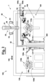
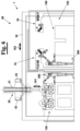
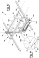
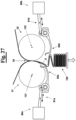
- figure 1 it is diagrammatically shown a first embodiment provided by the present invention of a machine 1 for producing packages of folded or interfolded laminar products made of paper material, in particular packages of napkins, tissues, towels, or similar products.
- the machine 1 comprises, in particular, a support frame 100 configured to support a feeding group 10 adapted to feed at least one web of paper 5, preferably a first and a second web of paper 5a and 5b, along a respective predetermined feeding direction 105a and 105b.
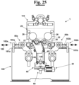
- the machine 1 comprises a folding or interfolding group 30 equipped with a first and a second folding or interfolding roll 31 and 32.
- a cutting group 20 is, furthermore, provided configured to cut the, or each, web of paper 5 into a respective plurality of sheets 6 of predetermined length.
- the folding or interfolding rolls 31 and 32 are configured to rotate about respective longitudinal rotation axes 131 and 132 in such a way to be counter-rotating with respect to each other, and to fold or interfold the or each aforementioned plurality of sheets of paper 6 at a folding or interfolding zone 35. In this way a stack 150 is obtained of sheets which are folded or interfolded according to a predetermined folding or interfolding configuration growing in height along a predetermined forming direction.
- the cutting group 20 and the folding or interfolding group 30 are mounted on the same support body 110.
- the support body 110 is configured to move between an assembled position, in which is supported by the support frame 100, and a disassembled position, in which is, instead, not supported by the support frame 100.
- the support body 110 can be positioned in a store area 130, for example in order to be subject to ordinary or extraordinary maintenance operations, before being positioned, again, in the machine 1, and precisely on the support frame 100.
- the machine 1 furthermore, comprises a displacement group 50 configured to displace the support body 110 between the assembled position and the disassembled position.
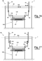
- the displacement group 50 and the support body 110 are provided with respective engagement portions 58 and 118 configured to engage with each other, in particular in a removable way, in such a way to allow the displacement group 50 to cause the displacement of the support body 110 between the assembled position and the disassembled position with respect to the support frame 100.
- the displacement group 50 is configured to cause the movement of the support body 110 from the assembled position to the disassembled position by lifting the same from the support frame 100, and the opposite movement, i.e. from the disassembled position to the assembled position, by lowering the support body on the support frame 100.
- the displacement group 50 can be configured to displace the support body 110 at least along a first displacement direction 101.
- the first direction 101 can be a direction orthogonal to the longitudinal axes 131 and 132 of the folding or interfolding rolls 31 and 32. More precisely, the first direction 101 can be the direction along which the displacement group 50 is adapted to cause the aforementioned lifting with respect to the support frame 100 to move the support body 110 same from the assembled position to the disassembled position, or the aforementioned lowering, to move, instead, the support body 110 from the disassembled position to the assembled position.
- the aforementioned displacement group 50 can be, furthermore, configured to displace the support body 110 along a second displacement direction 102.
- the aforementioned displacement direction 102 can be a direction orthogonal to the first displacement direction 101.
- the cutting group 20 can provide a first and a second cutting roll 21 and 22 associated respectively to the first and to the second folding or interfolding roll, 31 and 32. More precisely, the cutting rolls 21 and 22 can be peripherally provided with a predetermined number of blades, and rotate about respective longitudinal axes to cut and, therefore, to divide, a respective web of paper 5a, 5b into a respective plurality of sheets 6 by operating in combination with a respective fixed counter-blade.
- the cutting group 20 can be of the type described in WO2020161571 in the name of the same Applicant.
- the cutting group 20 can comprise a first and a second fixed cutting device 21 and 22 respectively associated to the first and to the second folding or interfolding roll 31 and 32.
- the first and the second cutting device 21 and 22 comprises, respectively, a base portion 25 provided with at least a cutting blade 26.
- the first and second folding or interfolding rolls 31 and 32 are provided with respective pluralities of counter-blades 36 distributed along the respective tubular body.
- each web 5a, or 5b, in a respective plurality of sheets 6 is carried out directly on the folding or interfolding rolls 31 and 32 which then provide to fold or interfold the sheets 6 same according to a predetermined folding or interfolding configuration.
- the folding or interfolding rolls, 31 and 32 can be also peripherally provided with recesses 36' and the aforementioned counter-blades 36 alternating to each other, in such a way to avoid that at the folding zone 35 the counter-blades 36 of a roll 31 or 32 can compromise the folding or interfolding operation and/or cut the worked sheets 6.
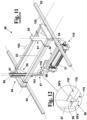
- the displacement group 50 can provide a first guide member 51 oriented along the first displacement direction 101, and, advantageously, a second guide member 52 oriented along a second displacement direction orthogonal to the aforementioned first displacement direction 101.
- the first guide member 51 can be mounted on a support member 55. This latter can be configured to slide along the second guide member 52.
- the support member 55 can comprise a base portion 56 and a sliding portion 57 configured to slide with respect to the base portion 56 along the aforementioned first guide member 51. More in particular, the sliding portion 57 can be provided with the engagement portion 58 configured to engage the respective engagement portion 118 of the support body 110.
- the sliding portion 57 can be provided with different engagement devices arranged to hook or engage the support body 110 to lift and to displace the same from and towards a store area 130, such as, for example, devices for providing a magnetic coupling, for example electromagnets, or a mechanical coupling.
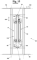
- the support member 55 can be configured to slide with respect to a third guide member 53 along a third displacement direction 103 orthogonal to the first and to the second displacement direction 101 and 102. In this way, it is possible to approach or move away the engagement portions 58 and 118 with respect to each other to cause them to move from the disengagement position shown in the figures 11 and 12 , to the engagement position shown in the figures 13 and 14 , and vice versa.
- the displacement group 50 can be a manipulator having at least two degrees of freedom.
- the two degrees of freedom are orthogonal to each other, but the possibility is also foreseen that the displacement group 50 can be configured to cause the movement of the support body 110 from the assembled position to the disassembled position, or vice versa, by a combination of movements comprising at least one translation and at least one rotation.
- the support member 55 can be adapted to move along the second guide member 52 and to be provided with two swinging arms, i.e. rotatably mounted on support member 55 and able to engage the support body 110 to lift the same from the support frame 100.
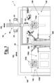
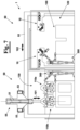
- the support member 55 can be configured to move, in particular integrally to the third guide member 53, with respect to the second guide member 52. In this way, it is possible to move the support member 55 and, therefore, the support body 110 that is supported by it, between a working area 120 and a store area 130. More in particular, within the store area 130 at least a second support body 110b can be positioned that have different characteristics, in particular in terms of size, with respect to the folding or interfolding group 30 and to the cutting members 20, in particular folding rolls 31b and 32b having a diameter different from the folding rolls 31a and 32a of a first support body 110a positioned within the working area 120, i.e. in the assembled position with respect to the support frame 100.
- the store area 130 and the working area 120 can be approached by at least one worker 300, advantageously through independent accesses 135 and 125, respectively.
- the worker 300 it is possible for the worker 300 to easily and quickly reach the aforementioned areas and any support body 110 that is in case positioned there in order to carry out ordinary or extraordinary maintenance operations.
- a worker whilst the paper converting line comprising the machine 1 is normally working, a worker can enter the store area 130 to carry out the maintenance operations on the support bodies 110 comprising the folding or interfolding group 30 and, if present, the cutting group 20.
- the displacement group 50 can be configured to alternately and selectively bring a first support body 110a in the disassembled position from the assembled position, and a second support body 110b from the disassembled position in the assembled position.
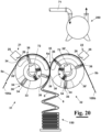
- each of the folding or interfolding rolls 31 and 32 can comprise a tubular body 33 configured to rotate about a respective longitudinal rotation axis 131 and 132.
- the tubular body 33 is provided with a plurality of suction holes 34 organized in a plurality of couples of longitudinal rows close to each other.
- a vacuum distribution device 38 can be, furthermore, provided that will not be described here in detail, but, for example, of the type that is described in EP1457444 or WO2020161571 , both in the name of the present Applicant.
- the vacuum distribution device 38 is configured to selectively pneumatically connect at least a vacuum generation device 250 to at least a row at a time of the aforementioned plurality of rows of suction holes 34, at predetermined angular positions of the tubular body 33, in such a way to cause the worked sheets of paper 6 to be sucked and to adhere at predetermined portions of the folding or interfolding roll 31 or 32.
- the vacuum distribution device and the or each vacuum generation device 250 are pneumatically connected to each other by a connection duct 70.
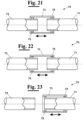
- This as diagrammatically shown in figure 20 , can comprise a first portion 71 integral to the vacuum distribution device 250 and a second portion 72, in particular a second portion 72 associated to each folding or interfolding roll 31 and 32, integral to the vacuum generation device 38.
- the first and second portions 71 and 72 can be adapted to move between a connection configuration ( figure 21 ), in which are adapted to pneumatically connect the vacuum generation device 250 to the vacuum distribution device 38, and a disconnection configuration ( figure 23 ), in which are adapted to pneumatically disconnect the vacuum distribution device 250 and the vacuum generation device 38.
- connection duct 70 can, furthermore, comprise a third portion 73 configured to move from a connection position ( figure 21 ) in which is adapted to pneumatically connect the first and the second portion of the connection duct 71 and 72 to each other that are, therefore, arranged in the connection configuration, and a disconnection position in which is adapted to pneumatically disconnect the first and second connection portions 71 and 72, which are, therefore, arranged in the aforementioned disconnection configuration.
- the third portion 73 can be slidingly mounted with respect to the first and second portions 71 and 72 of the connection duct 70 between the connection position, where is arranged in an advanced position, and the disconnection position, where is arranged in a retracted position. More in detail, at least one sealing element 75, for example an O-ring, positioned between the third portion 73 and the first and/or the second portion 71 and/or 72.
- the or each sealing element 75 can be configured to move from a working configuration, in which is adapted to exert a sealing action to pneumatically isolate the first and second portions 71 and 72 of the connection duct 70 from the external environment ( figure 21 ), and a rest configuration in which is not adapted to exert the aforementioned sealing action ( figures 22 and 23 ).
- the or each sealing element 75 can be pneumatically connected to an inflating device, which is not shown in figure for simplicity, adapted to cause the movement from the rest configuration to the working configuration, in particular by introducing air, or another gas, into each sealing element.
- the third portion 73 it is possible to cause the third portion 73 to slide from the connection position to the disconnection position and vice versa, when the or each sealing element 75 is in the rest configuration. More in particular, when the or each sealing element 75 is arranged in the working configuration, it can be adapted to prevent, or obstruct, the third portion 73 from sliding.
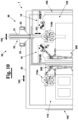
- the machine 1 comprises, furthermore, a motor group 40 configured to cause at least one between the first and second folding or interfolding rolls 31 and 32 to rotate about the respective rotation axis 131 and 132.
- the motor group 40 can be configured to operate the aforementioned rotation by a main motor 41 and a motion transmission device 42 configured to transmit the rotational motion of the rotation shaft, which is not shown in figure for simplicity, of the main motor 41 to at least one between the first and second folding or interfolding rolls 31 and 32.
- the motion transmission device 42 can comprise a first transmission member 43, for example a first toothed belt 43.
- the first transmission member 43 can mesh with a main deflection wheel 44 in such a way to cause it to rotate about a rotation axis 144.
- the motion transmission device 42 can comprise, furthermore, a rotation shaft 145 coaxially arranged to the main deflection wheel 44 and integral to it. Therefore, the aforementioned rotational motion of the main deflection wheel 44 causes also the rotation shaft 145 to rotate about the rotation axis 144.
- the motion transmission device 42 can comprise, furthermore, at least a second motion transmission member, for example a second toothed belt 45, which is mounted on the aforementioned rotation shaft 145 and on a series of guide pulleys 46 defining a predetermined sliding path.
- the second motion transmission member 45 is adapted to mesh with a motion transmission portion 37 integral to the first, or second folding or interfolding roll, 31 or 32, in such a way to cause a rotation about the respective longitudinal rotation axis 131 or 132.
- the group for adjusting the tension 60 can be configured to keep constant, or substantially constant, the tension of the motion transmission device 42, preferably of the second transmission member 45, in particular during the movement of the support body 110 between the assembled position and the disassembled position carried out by the displacement group 50.
- the second motion transmission member 45 in particular the toothed belt, is correctly positioned with respect to the different movable parts remaining on the support frame 100. Therefore, it is ensured that the different parts of the machine 1 are able to correctly work when the machine 1 is operated again and arranged in working conditions.
- the transmission of the motion of the motor shaft of the main motor 41 to the rotation shaft 145 can be obtained by using as motor shaft 145 the motor shaft of the main motor 41, i.e. mounting the same coaxially to the rotation axis 144.
- the group for adjusting the tension 60 comprises a measurement device 63, for example a force sensor, such as a load cell, advantageously configured to measure the tension on the second motion transmission member 45.
- a measurement device 63 for example a force sensor, such as a load cell, advantageously configured to measure the tension on the second motion transmission member 45.
- the measurement device 63 can be operatively connected to a processing device 200 configured to operate an actuation device 65.
- the actuation device 65 can be configured to cause a lengthening or a shortening of the path of the motion transmission member 45 depending on the tension signal detected by the aforementioned measurement device 63.
- the motion transmission belt 45 can be mounted on a series of guide pulleys or rollers 46 and 47 at least one of which able to move along a predetermined direction.
- the transmission belt 45 can be mounted on a series of fixed guide pulleys 46 and on at least one movable guide pulley 47, for example on two movable guide pulleys 47.
- the actuation device 65 can be arranged to lengthen or to shorten the path of the transmission belt 45 thus causing the or each movable guide pulley 47 to move away from the fixed guide pulleys 46.
- the actuation device 65 can comprise a motor 61 configured to cause the or each movable guide pulley 47 to move along a predetermined actuation direction 162 by an actuation device 65.
- the tension of the transmission belt 45 tends to gradually reduce that the aforementioned support body 110 is lifted and, therefore, progressively disengaged from the transmission belt 45.
- the group for adjusting the tension 60 can be operated by the processing device 200 to keep the tension of the transmission belt 45 constant or substantially constant, by operating the actuation device 65.
- the tension of the transmission belt 45 tends to increase during the positioning of a new support body 110 which engages with the motion transmission portion 37 of one between the folding or interfolding rolls 31 and 32.
- the group for adjusting the tension 60 can be operated by the processing device 200 to keep constant the tension of the transmission belt 45.
- the tension adjustment device 60 can be used also during the normal working conditions of the machine 1 to keep the transmission belt 45 constantly at a determined correct working tension. In this way both overloads and loosening, which could cause the loss of phase between the folding rolls 31 and 32 with other components of the machine 1 exposing to the risk of jamming, are avoided, or malfunctions in general that in the worst cases can cause the machine 1 to be damaged.
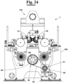
- the machine 1 can comprise, furthermore, a first and a second plurality of detaching fingers 85a and 85b configured to cause respectively the detachment of the folded or interfolded sheets of paper 6, from the first and second folding or interfolding roll 31 and 32, in particular from their external lateral surface.
- a first and a second driving group 80a and 80b are provided configured, respectively, to cause a oscillatory back and forth motion of the first and second pluralities of detaching fingers 85a and 85b towards the or from the folding or interfolding zone 35, in such a way to cause the detachment of the sheets of paper 6, respectively, from the first and second folding or interfolding roll 31 and 32.
- the first and second driving groups 80a and 80b can be configured to convert the rotational motion of a motor, or of a respective motor, in an oscillatory back and forth motion that is transmitted to the first and second pluralities of detaching fingers 85a and 85b.
- a transmission device can be provided operated by a main motor 41, not shown in the figure, configured to cause the first and second driving groups 80a and 80b to rotate and that is, therefore, converted in an oscillatory motion.
- the first and second driving groups 80a and 80b can be configured to bring, respectively, the first and second pluralities of detaching fingers 85a and 85b in a predetermined reference position, preferably corresponding to the position of top dead centre of the detaching fingers 85a and 85b during the respective back and forth motion.
- the reference position can be a position where the detaching fingers 85a and 85b do not have mechanical interference with other components of machine 1, in particular with the folding or interfolding rolls 31 and 32 and with the cutting blades 36.
- the first and second driving groups 80a and 80b are arranged to move, respectively, the first and second pluralities of detaching fingers 85a and 85b in the reference position before that the displacement group 50 is arranged to move the support body 110 between the assembled position and the disassembled position.
- the first and second driving groups 80a and 80b are arranged to move, respectively, the first and second pluralities of detaching fingers 85a and 85b in the reference position before that the displacement group 50 is arranged to move the support body 110 between the assembled position and the disassembled position.
- the first and second driving groups 80a and 80b can be configured to delay or anticipate the oscillatory motion of the first and second pluralities of detaching fingers 85a and 85b with respect to a predetermined reference oscillatory motion. In this way, it is possible to delay or anticipate the instant (tr) at which the first and second pluralities of detaching fingers 85a and 85b are arranged to cause the detachment of the sheets of paper 6 folded or interfolded, respectively from the first and the second folding or interfolding roll 31 and 32.
- This particular technical solution allows to adjust the motion of the detaching fingers 85a and 85b on the basis of the type of support body 110 installed in the machine 1, in particular of the diameter of the folding or interfolding rolls 31 and 32, of the number of blades 36 of which they are, in case, provided with, and of the other parameters of the cutting group 20 and/or of the folding or interfolding group 30 installed on the support body 110 arranged in the assembled position.
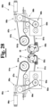
- the first and second driving groups 80a and 80b can be, advantageously, associated, respectively, to a first and a second phase adjustment device 90a and 90b configured to adjust the phase of the first and second pluralities of detaching fingers 85a and 85b with the respective folding or interfolding rolls 31 and 32.
- the first and the second phase adjustment device 90a and 90b are adapted to anticipate, or postpone, the instant tr at which the first and second pluralities of detaching fingers 85a, 85b are adapted to hit the web or sheet of paper to cause it to be detached from the respective folding or interfolding roll 31 and 32.
- the first and second phase adjustment devices 90a and 90b can comprise, respectively, a first and a second epicycloidal gear 95a, and 95b. More precisely, in this case, the first and second epicycloidal gear 95a and 95b can be operatively connected respectively to a first and a second motor group 91a and 91b, for example by a first transmission belt 87a, and 87b, and to a first and a second driving device 92a and 92b by a second transmission belt 88a and 88b. More precisely, the first and second driving device 92a and 92b are adapted to transmit the rotational motion generated by the first and second motor groups 91a and 91b, respectively to the first and to the second driving group 80a and 80b.
- the first and second epicycloidal gears 95a and 95b are, respectively, provided with a first and a second electric motor 96a and 96b. These are adapted to adjust the velocity of rotation of the first and of the second driving device 92a and 92b adjusting the velocity and the direction of rotation of a first and of a second epicycloidal gear, not shown in the figure for simplicity, housed, respectively, within the first and the second epicycloidal gear 95a and 95b.
- the first and second electric motors 96a and 96b can be normally still in such a way not to change the phase of the detaching fingers 85a and 85b with respect to the other parts of the machine 1, in particular the folding rolls 31 and 32. If it is necessary to change the phase of the first and of the second plurality of detaching fingers 85a and 85b, for example as a consequence of the replacement of a support body 110 with another, the first and the second electric motors 96a and 96b are operated to actuate, respectively, the first and second epicycloidal gears in such a way to temporarily accelerate or decelerate the second transmission belt 88a and 88b.
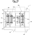
- the first and second driving groups 80a and 80b can be configured to translate one with respect to the other in order to approach or move away with respect to each other. In this way, it is possible to adjust the distance between them and in particular the distance with respect to the respective folding or interfolding rolls 31 and 32, in case that a support body 110 is replaced with another support body 110 equipped with folding or interfolding rolls 31 and 32 having a very different diameter with respect to the previous.
- the first and second driving groups 80a and 80b can be slidingly mounted along a predetermined sliding direction 180, in particular orthogonal to the axed 131 and 132 of the folding or interfolding rolls 31 and 32.
- first and second driving groups 80a and 80b can be mounted on a sliding group 185 configured to symmetrically approach or move away with respect to a plane of symmetry of the folding or interfolding rolls 31 and 32.
- first and second driving groups 80a and 80b can be mounted on a slide 181 arranged along the aforementioned sliding direction 180.
- a first and a second motor device 182a and 182b can be provided operatively connected, respectively, to the first and to the second driving group 80a and 80b by a respective connection member 183a and 183b.
- first and second connection members 183a and 183b for example an actuation rod
- the first and the second driving group 80a and 80b by operating, correspondingly, the first and second motor devices 182a and 182b.
- only one motor device 182 is provided configured to symmetrically move through a connection device 183 the first and second driving groups 80a and 80b.
- a step of positioning the detaching fingers 85a and 85b in a reference position can be provided at the moment of replacing a first support body 110a with a second support body 110b.
- the displacement group 50 can be, then, operated in such a way to engage the first support body 110a to be replaced at respective engagement portions 58 and 118.
- the engagement portions 58 and 118 can be provided with respective contacting surfaces 59 and 119.
- the engagement portions 58 and 118 can be provided, respectively, with at least a first contacting surface 59 and with at least a second contacting surface 119.
- the aforementioned contacting surfaces 59 and 119 of the engagement portions 58 and 118 are positioned in contact with each other ( figure 14 ).
- each engagement portion 58 and 118 is provided with 3 contacting surfaces 59 and 119.
- the engagement portions 58 and 118 can be configured in such a way that during the movement from the assembled position to the disassembled position and vice versa, no relative motion occurs between the aforementioned respective contacting surfaces 59 and 119, or, however, there is no significant relative motion, that means excluding relative motion due to vibrations, or stresses, produced on the same during the displacement by the displacement group 50.
- the contacting surface 119 of the engagement portion 118 is adapted to be in contact, for example to lay above, with the contacting surface 59 of the engagement portion 58 of the displacement group 50.
- the engagement portion 58 can provide a portion protruding from the sliding portion 57, advantageously orthogonal to this. More precisely, the engagement portion 58 protruding from the sliding portion 57 can be configured to laterally contain an end portion 118' of the engagement portion 118, for example substantially flat.
- the engagement portion 58 can be substantially "U-shaped" or "V-shaped”.
- a first and a second lateral wall 59'a and 59'b are adapted to laterally contain the engagement portion 118 at least at the aforementioned end portion 118' during the displacement between the assembled position and the disassembled position, in particular during the lifting or the lowering of the support body 110 with respect to the support frame 100 (see figure 14 ).
- the engagement portions 58 and 118 can be configured to interlock with each other.
- the first support body 110a once engaged can be displaced by the displacement group 50 at the store area 130 where is positioned at a determined storing position 132a. Then, the displacement group 50 engages a second support body 110b, in particular positioned at a corresponding storing position. The second support body 110b is, therefore, displaced by the displacement group 50 at the working area 120, and, then, positioned on the support frame 100. Once that the second support body 110b has been moved in the assembled position, the detaching fingers 85a and 85b are, then, moved from the reference position to the working position in order to start a new production cycle.
- connection duct 70 is of the type described above with reference to the figures from 21 to 23
- the steps can be, furthermore, provided of positioning the aforementioned first and second portions 71 and 72 in the disconnection configuration, before displacing by the displacement group 50 the first support body 110a from the working area 120 to the store area 130.
- the first and second portions 71 and 72 of the connection duct 70 are arranged in the connection configuration.
- the aforementioned step of engaging by the engagement portions the displacement group 50 and the support body 110 and of positioning the first and second portions 71 and 72 of the connection duct 70 in the disconnection position can be carried out simultaneously, or one before the other. The same can be said for the steps of positioning the first and second portions 71 and 72 of the connection duct 70 in the connection position and the positioning of the detaching fingers 85a and 85b from the reference position to the working position.
- a step can be provided of approaching or moving the detaching fingers 85a and 85b away with respect to each other, before displacing the support body 110a by the displacement group 50 to the store area 130.
- a step can be also provided of repositioning the detaching fingers 85a and 85b with respect to the folding or interfolding rolls 31 and 32 in a predetermined position before positioning the detaching fingers 85a and 85b in the working position.
- all the aforementioned steps, or at least a part of these, can be automatically managed, operated and controlled by the processing device 200.
- the new support body 110 has been positioned on the support frame 100, it is possible to block it by blocking devices in such a way to constrain their relative position.
- the blocking devices are not shown in the figure for simplicity.
- this further step can be omitted.
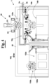
- the displacement group 50 comprises a first and a second support member 55a and 55b, advantageously, slidingly mounted on the same second guide member 52.
- each support member 55a and 55b can be configured to be positioned between a picking up position, at which is adapted to pick a respective support body 110 up, at the working area 120 or store area 130, and a waiting position, at which are adapted to engage outside the working area 120 and the store area 130, the support body 110 at the working area 120, or the store area 130, and then releasing the same at the store area 130, or the working area 120, where the aforementioned displacement of the support body 110 from the assembled position to the disassembled position can be carried out.
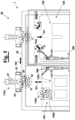
- the displacement group 50 is configured to move the support body 110 between the assembled position and the disassembled position by a rotation about at least a rotation axis 113, in particular parallel to the longitudinal rotation axes 131 and 132 of the folding or interfolding rolls 31 and 32.
- the displacement group 50 can comprise a first and a second displacement device 50a and 50b, for example a hydraulic, or pneumatic, or electromechanical, actuator, each of which operatively connected at a first engagement portion 50'a and 50'b to a respective support body 110a and 110b and pivotally connected, at a second engagement portion 50"a and 50"b, to the support frame 100.
- Each support body 110a and 110b can be, furthermore, pivotally connected to the support frame 100 at a respective point.
- a support body for example the support body 110b
- the respective displacement device 50b to cause the rotation of the support body 110a, or 110b, about a respective longitudinal rotation axis 113a, or 113b.
Landscapes
- Folding Of Thin Sheet-Like Materials, Special Discharging Devices, And Others (AREA)
Claims (15)
- Maschine (1) zur Herstellung von Verpackungen aus gefalteten oder ineinandergefalteten laminaren Produkten aus Papiermaterial, insbesondere Verpackungen von Servietten, Taschentüchern, Handtüchern oder ähnlichen Produkten, wobei die Maschine (1) einen Stützrahmen (100) umfasst, der konfiguriert ist, um Folgendes zu stützen:- eine Zufuhrgruppe (10), die konfiguriert ist, um eine erste und eine zweite Papierbahn (5a, 5b) jeweils entlang einer ersten und einer zweiten vorbestimmten Zufuhrrichtung (105a, 105b) zuzuführen;- eine Schneidgruppe (20), die konfiguriert ist, um die erste und die zweite Papierbahn (5a, 5b) jeweils in eine erste und eine zweite Vielzahl von Papierlagen (6) von vorbestimmter Länge zu schneiden;- eine Falt- oder Ineinanderfaltgruppe (30), die mit einer ersten und einer zweiten gegendrehenden Faltrolle (31, 32) ausgestattet ist, die ausgelegt ist, um sich um jeweilige Längsdrehachsen (131, 132) zu drehen, und konfiguriert ist, um die erste und die zweite Vielzahl von Papierlagen (6) in einer Falt- oder Ineinanderfaltzone (35) auf eine solche Weise zu falten oder ineinanderzufalten, um einen Stapel (150) von Lagen zu erhalten, der gemäß einer vorbestimmten Falt- oder Ineinanderfaltkonfiguration gefaltet oder ineinandergefaltet ist, wobei die Schneidgruppe (20) und die Falt- oder Ineinanderfaltgruppe (30) auf einem gleichen Stützkörper (110) montiert sind, der konfiguriert ist, um sich zwischen einer zusammengebauten Position, in der er ausgelegt ist, um durch den Stützrahmen (100) gestützt zu werden, und einer demontierten Position, in der er nicht ausgelegt ist, um durch den Stützrahmen (100) gestützt zu werden, zu bewegen;- eine Verschiebungsgruppe (50), die konfiguriert ist, um den Stützkörper (110) zwischen der zusammengebauten Position und der demontierten Position zu verschieben;wobei die Maschine (1) dadurch gekennzeichnet ist, dass die Verschiebungsgruppe (50) konfiguriert ist, um den Stützkörper (110) von der zusammengebauten Position zu der demontierten Position zu verschieben, indem der Stützkörper (110) von dem Stützrahmen (100) angehoben wird, und um den Stützkörper (110) von der demontierten Position zu der zusammengebauten Position zu verschieben, indem der Stützkörper (110) auf dem Stützrahmen (100) abgesenkt wird, und dass die Verschiebungsgruppe (50) und der Stützkörper (110) mit jeweiligen Eingriffsabschnitten (58, 118) bereitgestellt sind, die konfiguriert sind, um auf eine solche Weise ineinander einzugreifen, um zu ermöglichen, dass die Verschiebungsgruppe (50) den Stützkörper (110) zwischen der zusammengebauten Position und der demontierten Position in Bezug auf den Stützrahmen (100) verschiebt.
- Maschine (1) gemäß Anspruch 1, wobei die Verschiebungsgruppe (50) konfiguriert ist, um den Stützkörper (110) entlang einer ersten Verschiebungsrichtung (101), entlang der er ausgelegt ist, um den Stützkörper (110) in Bezug auf den Stützrahmen (100) anzuheben oder abzusenken, und zumindest entlang einer zweiten Verschiebungsrichtung (102) zu verschieben.
- Maschine (1) gemäß Anspruch 2, wobei die erste und die zweite Verschiebungsrichtung (101, 102) orthogonal zueinander sind.
- Maschine (1) gemäß Anspruch 2, wobei die Verschiebungsgruppe (50) Folgendes bereitstellt:- ein erstes Führungsglied (51), das entlang der ersten Verschiebungsrichtung (101) ausgerichtet ist;- ein zweites Führungsglied (52), das entlang der zweiten Verschiebungsrichtung (102) ausgerichtet ist;- ein Stützglied (55), das konfiguriert ist, um entlang des zweiten Führungsglieds (52) zu gleiten, wobei das Stützglied (55) mit Folgendem bereitgestellt ist:- einem Basisabschnitt (56), der mit dem ersten Führungsglied (51) bereitgestellt ist;- einem Gleitabschnitt (57), der ausgelegt ist, um gleitend entlang des ersten Führungsglieds (51) in Bezug auf den Basisabschnitt (56) montiert zu sein, wobei der Gleitabschnitt (57) mit dem Eingriffsabschnitt (58) bereitgestellt ist.
- Maschine (1) gemäß einem der vorhergehenden Ansprüche, wobei eine Motorgruppe (40) ferner noch bereitgestellt ist, die konfiguriert ist, um zu bewirken, dass sich zumindest eine zwischen der ersten und der zweiten Falt- oder Ineinanderfaltrolle (31, 32) um eine jeweilige Drehachse (131, 132) dreht, wobei die Motorgruppe (40) Folgendes umfasst:- einen Hauptmotor (41);- eine Bewegungsübertragungsvorrichtung (42), die zumindest ein Bewegungsübertragungsglied (45) umfasst, das konfiguriert ist, um die Drehbewegung einer Drehwelle des Hauptmotors (41) auf zumindest eine zwischen der ersten und der zweiten Falt- oder Ineinanderfaltrolle (31, 32) zu übertragen.
- Maschine (1) gemäß Anspruch 5, wobei eine Gruppe zum Einstellen der Spannung (60) ferner noch bereitgestellt ist, die konfiguriert ist, um die Spannung des Bewegungsübertragungsglieds (42) einzustellen, wobei die Gruppe zum Einstellen der Spannung (60) konfiguriert ist, um die Spannung des Bewegungsübertragungsglieds (45) während der Bewegung des Stützkörpers (110) zwischen der zusammengebauten Position und der demontierten Position, die durch die Verschiebungsgruppe (50) ausgeführt wird, im Wesentlichen konstant zu halten.
- Maschine (1) gemäß Anspruch 6, wobei die Gruppe zum Einstellen der Spannung (60) eine Messvorrichtung (63) umfasst, die konfiguriert ist, um die Spannung an dem Bewegungsübertragungsglied (45) zu messen, wobei die Messvorrichtung (63) mit einer Verarbeitungsvorrichtung (200) wirkverbunden ist, die konfiguriert ist, um eine Betätigungsvorrichtung (65) zu betreiben, die konfiguriert ist, um eine Verlängerung oder eine Verkürzung des Weges des Bewegungsübertragungsglieds (45) gemäß einem Spannungssignal, das durch die Messvorrichtung (63) gemessen wird, zu bewirken, wobei das Bewegungsübertragungsglied (45) gleitend entlang eines vorbestimmten Weges, der durch eine Vielzahl von Führungsscheiben (46, 47) definiert ist, montiert ist, und wobei die Betätigungsvorrichtung (65) konfiguriert ist, um die Führungsscheiben (46, 47) nahe aneinander zu bringen, auf eine solche Weise, um eine Verkürzung des Weges zu bewirken, oder um die Führungsscheiben (46, 47) voneinander weg zu bewegen, auf eine solche Weise, um eine Verlängerung des Weges zu bewirken.
- Maschine (1) gemäß einem der vorhergehenden Ansprüche, wobei jede von der ersten und der zweiten Falt- oder Ineinanderfaltrolle (31, 32) Folgendes umfasst:- einen rohrförmigen Körper (33), der konfiguriert ist, um sich um eine jeweilige Längsdrehachse (131, 132) zu drehen, wobei der rohrförmige Körper (33) mit einer Vielzahl von Sauglöchern (34) bereitgestellt ist, die in einer Vielzahl von Paaren von Längsreihen nahe aneinander organisiert ist;- eine Vakuumverteilungsvorrichtung (38), die konfiguriert ist, um eine Vakuumerzeugungsvorrichtung (250) selektiv pneumatisch zu verbinden, die konfiguriert ist, um einen vorbestimmten Vakuumgrad an zumindest einer Reihe der vorgenannten Vielzahl von Reihen von Sauglöchern (34) an vorbestimmten Winkelpositionen des rohrförmigen Körpers (33) zu erzeugen, auf eine solche Weise, um zu bewirken, dass die erste und die zweite Vielzahl von bearbeiteten Papierlagen (6) angesaugt werden und daher an vorbestimmten Abschnitten der Falt- oder Ineinanderfaltrolle (31, 32) haften, wobei die Vakuumverteilungsvorrichtung und die Vakuumerzeugungsvorrichtung ausgelegt sind, um durch einen Verbindungskanal (70) pneumatisch verbunden oder getrennt zu sein, umfassend:wobei der dritte Abschnitt (73) ausgelegt ist, um gleitend in Bezug auf den ersten und den zweiten Abschnitt (71, 72) des Verbindungskanals (70) zwischen einer eingezogenen Position entsprechend der Trennkonfiguration und einer vorgeschobenen Position entsprechend der Verbindungskonfiguration montiert zu sein, und wobei zumindest ein Dichtungselement (75) ferner noch bereitgestellt ist, das zwischen dem dritten Abschnitt (73) und dem ersten und/oder zweiten Abschnitt (71, 72) positioniert ist.- einen ersten Abschnitt (71), der einstückig mit der Vakuumverteilungsvorrichtung (38) ist;- einen zweiten Abschnitt (72), der einstückig mit der Vakuumerzeugungsvorrichtung (250) ist, wobei der erste und der zweite Abschnitt (71, 72) konfiguriert sind, um sich zwischen einer Verbindungskonfiguration, in der sie ausgelegt sind, um die Vakuumerzeugungsvorrichtung (250) pneumatisch mit der Vakuumverteilungsvorrichtung (38) zu verbinden, und einer Trennkonfiguration, in der sie ausgelegt sind, um die Vakuumverteilungsvorrichtung (38) pneumatisch mit der Vakuumerzeugungsvorrichtung (250) zu verbinden, zu bewegen- einen dritten Abschnitt (73), der konfiguriert ist, um die Bewegung des ersten und des zweiten Abschnittes des Verbindungskanals (71, 72) zwischen der Verbindungskonfiguration und der Trennkonfiguration zu bewirken,
- Maschine gemäß einem der vorhergehenden Ansprüche, wobei die Schneidgruppe (20) eine erste und eine zweite Schneidvorrichtung (21, 22) umfasst, die jeweils mit zumindest einer ersten und einer zweiten Schneidklinge (26) bereitgestellt sind, die jeweils mit der ersten und der zweiten Falt- oder Ineinanderfaltrolle (31, 32) assoziiert sind, und wobei die erste und die zweite Falt- oder Ineinanderfaltrolle (31, 32) jeweils mit einer ersten und einer zweiten Vielzahl von Gegenklingen (36) bereitgestellt sind, die konfiguriert sind, um jeweils in Kombination mit der ersten und der zweiten Schneidklinge (26) zu arbeiten, um die jeweilige Papierbahn (5a, 5b) in die jeweilige Vielzahl von Papierlagen (6) zu schneiden.
- Maschine gemäß einem der vorhergehenden Ansprüche, wobei ferner noch Folgendes bereitgestellt ist:- eine erste und eine zweite Vielzahl von Ablösefingern (85a, 85b), die jeweils konfiguriert sind, um zu bewirken, dass die gefalteten oder ineinandergefalteten Papierlagen (6) von der ersten und von der zweiten Falt- oder Ineinanderfaltrolle (31, 32) gelöst werden;- eine erste und eine zweite Antriebsgruppe (80a, 80b), die jeweils konfiguriert sind, um eine oszillierende Hin- und Herbewegung der ersten und der zweiten Vielzahl von Ablösefingern (85a, 85b) zu/von der Falt- oder Ineinanderfaltzone (35) auf eine solche Weise zu bewirken, um zu bewirken, dass die gefalteten oder ineinandergefalteten Papierlagen (6) von der ersten und von der zweiten Falt- oder Ineinanderfaltrolle (31, 32) gelöst werden, wobei die erste und die zweite Antriebsgruppe (80a, 80b) ausgelegt sind, um jeweils die erste und die zweite Vielzahl von Ablösefingern (85a, 85b) in einer vorbestimmten Referenzposition zu bewegen, bevor die Verschiebungsgruppe (50) ausgelegt ist, um den Stützkörper (110) zwischen der zusammengebauten Position und der demontierten Position zu bewegen.
- Maschine gemäß einem der vorhergehenden Ansprüche, wobei die Eingriffsabschnitte (58, 118) mit jeweiligen Kontaktflächen (59, 119) bereitgestellt sind, die während der Bewegung durch die Verschiebungsgruppe (50) zwischen der zusammengebauten Position und der demontierten Position in Kontakt miteinander positioniert sind, und wobei die Eingriffsabschnitte (58, 118) auf eine solche Weise konfiguriert sind, dass sich während der Bewegung durch die Verschiebungsgruppe (50) zwischen der zusammengebauten Position und der demontierten Position die Kontaktflächen (59, 119) nicht in Bezug zueinander bewegen.
- Verfahren zur Herstellung von Verpackungen aus gefalteten oder ineinandergefalteten laminaren Produkten aus Papier, insbesondere Verpackungen von Servietten, Taschentüchern, Handtüchern oder ähnlichen Produkten, wobei das Verfahren die folgenden Schritte umfasst:- Zuführen einer ersten und einer zweiten Papierbahn (5a, 5b) jeweils entlang einer ersten und einer zweiten Zufuhrrichtung;- Schneiden der ersten und der zweiten Papierbahn jeweils in eine erste und in eine zweite Vielzahl von Lagen (6) von vorbestimmter Länge durch eine Schneidgruppe (20);- Falten oder Ineinanderfalten der ersten und der zweiten Vielzahl von Papierlagen in einer vorbestimmten Falt- oder Ineinanderfaltzone (35),wobei der Falt- oder Ineinanderfaltschritt durch eine Falt- oder Ineinanderfaltgruppe (30) durchgeführt wird, die eine erste und eine zweite gegendrehende Falt- oder Ineinanderfaltrolle (31, 32) umfasst, zwischen denen die Falt- oder Ineinanderfaltzone (35) definiert ist;wobei die Schneidgruppe und die Falt- oder Ineinanderfaltgruppe auf einem gleichen Stützkörper (110) montiert sind, der konfiguriert ist, um sich zwischen einer zusammengebauten Position, in der er durch einen Stützrahmen gestützt wird, und einer demontierten Position, in der er nicht durch den Stützrahmen gestützt wird, zu bewegen;- Verschieben des Stützkörpers (110) zwischen der zusammengebauten Position und der demontierten Position;wobei das Verfahren dadurch gekennzeichnet ist, dass der Verschiebungsschritt ausgeführt wird, indem eine Verschiebungsgruppe (50) und der Stützkörper (110) an jeweiligen Eingriffsabschnitten (58, 118) in Eingriff gebracht werden und der Stützkörper (110) durch die Verschiebungsgruppe (50) auf eine solche Weise angehoben wird, um zu ermöglichen, dass die Verschiebungsgruppe (50) die Verschiebung des Stützkörpers (110) von der zusammengebauten Position zu der demontierten Position bewirkt und Absenken des Stützkörpers (110) durch die Verschiebungsgruppe (50) auf eine solche Weise, um zu ermöglichen, dass die Verschiebungsgruppe (50) die Verschiebung des Stützkörpers (110) von der demontierten Position zu der zusammengebautenn Position in Bezug auf den Stützrahmen (100) bewirkt.
- Verfahren gemäß Anspruch 12, wobei ein erster und ein zweiter Stützkörper (110a, 110b) bereitgestellt sind und wobei die folgenden Schritte bereitgestellt sind:- Eingreifen des Eingriffsabschnittes (58, 118) in den ersten Stützkörper (110a) und der Verschiebungsgruppe (50) an einem Arbeitsbereich (120);- Anheben des ersten Stützkörpers (110a), der an dem Arbeitsbereich (120) positioniert ist, durch die Verschiebungsgruppe (50), um den ersten Stützkörper (110a) von der zusammengebauten Position zu der demontierten Position zu bewegen;- Verschieben des ersten Stützkörpers (110a) durch die Verschiebungsgruppe (50) von dem Arbeitsbereich (120) zu einem Lagerbereich (130);- Positionieren des ersten Stützkörpers (110a) an einer ersten Lagerposition (132a), die an dem Lagerbereich (130) vorhanden ist;- Lösen des ersten Stützkörpers (110a) und der Verschiebungsgruppe (50);- Positionieren der Verschiebungsgruppe (50) an einer zweiten Lagerposition (132b), die an dem Lagerbereich (130) vorhanden ist, an dem der zweite Stützkörper (110b) positioniert ist;- Eingreifen der Eingriffsabschnitte (58, 118) in den zweiten Stützkörper (110b) und der Verschiebungsgruppe (50);- Verschieben des zweiten Stützkörpers (110b) von dem Lagerbereich (130) zu dem Arbeitsbereich (120);- Absenken des zweiten Stützkörpers (110b) durch die Verschiebungsgruppe (50) an dem Arbeitsbereich (120), um den zweiten Stützkörper (110b) von der demontierten Position zu der zusammengebauten Position zu bewegen;- Lösen des zweiten Stützkörpers (110b) und der Verschiebungsgruppe (50), wodurch bewirkt wird, dass sich die jeweiligen Eingriffsabschnitte von der Eingriffsposition in die Löseposition bewegen.
- Verfahren gemäß Anspruch 24, wobei ferner eine erste und eine zweite Vielzahl von Ablösefingern (85a, 85b) ferner noch bereitgestellt sind, die konfiguriert sind, um zu bewirken, dass die gefalteten oder ineinandergefalteten Papierlagen (6) jeweils von der ersten und der zweiten Falt- oder Ineinanderfaltrolle (31, 32) gelöst werden, und wobei ferner noch die folgenden Schritte bereitgestellt sind:- Positionieren der Ablösefinger (85a, 85b) in einer vorbestimmten Referenzposition;- Verschieben des ersten Stützkörpers (110) durch die Verschiebungsgruppe (50) von dem Arbeitsbereich (120) zu dem Lagerbereich (130);- Verschieben des zweiten Stützkörpers (110) durch die Verschiebungsgruppe (50) von dem Lagerbereich (130) zu dem Arbeitsbereich (120);- Positionieren der Ablösefinger (85a, 85b) von der Referenzposition zu einer Arbeitsposition.
- Verfahren gemäß Anspruch 14, wobei eine Vakuumverteilungsvorrichtung (38) ferner noch bereitgestellt ist, die konfiguriert ist, um eine Vakuumerzeugungsvorrichtung (250) selektiv pneumatisch zu verbinden, die konfiguriert ist, um einen vorbestimmten Vakuumgrad mit zumindest einer Reihe der vorgenannten Vielzahl von Reihen von Sauglöchern (34) an vorbestimmten Winkelpositionen des rohrförmigen Körpers (33) auf eine solche Weise zu erzeugen, um zu bewirken, dass die erste und die zweite Vielzahl von bearbeiteten Papierlagen (6) angesaugt werden und daher an vorbestimmten Abschnitten der Falt- oder Ineinanderfaltrolle (31, 32) haften, wobei die Vakuumverteilungsvorrichtung und die Vakuumerzeugungsvorrichtung ausgelegt sind, um durch einen Verbindungskanal (70) pneumatisch verbunden oder getrennt zu sein, umfassend:- einen ersten Abschnitt (71), der einstückig mit der Vakuumverteilungsvorrichtung (38) ist;- einen zweiten Abschnitt (72), der einstückig mit der Vakuumerzeugungsvorrichtung (250) ist, wobei der erste und der zweite Abschnitt (71, 72) konfiguriert sind, um sich zwischen einer Verbindungskonfiguration, in der sie ausgelegt sind, um die Vakuumerzeugungsvorrichtung (250) pneumatisch mit der Vakuumverteilungsvorrichtung (38) zu verbinden, und einer Trennkonfiguration, in der sie ausgelegt sind, um die Vakuumerzeugungsvorrichtung (250) pneumatisch von der Vakuumverteilungsvorrichtung (38) zu trennen, zu bewegen;und wobei die folgenden Schritte bereitgestellt sind:- Bewirken der Bewegung des ersten und des zweiten Abschnittes (71, 72) von der Verbindungskonfiguration zu der Trennkonfiguration, bevor der erste Stützkörper (110a) durch die Verschiebungsgruppe (50) von dem Arbeitsbereich (120) zu dem Lagerbereich (130) verschoben wird;- Bewirken der Bewegung des ersten und des zweiten Abschnittes (71, 72) von der Trennkonfiguration zu der Verbindungskonfiguration, sobald der zweite Stützkörper (110b) durch die Verschiebungsgruppe (50) von dem Lagerbereich (130) zu dem Arbeitsbereich (120) bis zu der zusammengebauten Position verschoben worden ist.
Applications Claiming Priority (2)
| Application Number | Priority Date | Filing Date | Title |
|---|---|---|---|
| IT202100022133 | 2021-08-20 | ||
| PCT/IB2022/057554 WO2023021386A1 (en) | 2021-08-20 | 2022-08-12 | Machine for producing laminar products made of paper material, in particular packages of napkins, tissues or similar products and related production method |
Publications (3)
| Publication Number | Publication Date |
|---|---|
| EP4387910A1 EP4387910A1 (de) | 2024-06-26 |
| EP4387910C0 EP4387910C0 (de) | 2025-06-04 |
| EP4387910B1 true EP4387910B1 (de) | 2025-06-04 |
Family
ID=78463828
Family Applications (1)
| Application Number | Title | Priority Date | Filing Date |
|---|---|---|---|
| EP22768470.1A Active EP4387910B1 (de) | 2021-08-20 | 2022-08-12 | Maschine zur herstellung von laminaren produkten aus papiermaterial, insbesondere servietten, tissues oder ähnlichen produkten und zugehöriges herstellungsverfahren |
Country Status (4)
| Country | Link |
|---|---|
| US (1) | US20240351819A1 (de) |
| EP (1) | EP4387910B1 (de) |
| CN (1) | CN118043274A (de) |
| WO (1) | WO2023021386A1 (de) |
Families Citing this family (2)
| Publication number | Priority date | Publication date | Assignee | Title |
|---|---|---|---|---|
| WO2025174544A1 (en) | 2024-02-14 | 2025-08-21 | Bw Converting, Inc. | Machine for processing a web of material, and method for changing rolls on a machine |
| WO2025202832A1 (en) * | 2024-03-25 | 2025-10-02 | Ot Lucca S.R.L. | A multi-format interfolding machine and a corresponding method for format change |
Family Cites Families (7)
| Publication number | Priority date | Publication date | Assignee | Title |
|---|---|---|---|---|
| US5598758A (en) * | 1993-07-22 | 1997-02-04 | Moore Business Forms, Inc. | Quick change cassette hole punch unit |
| DE10122113A1 (de) * | 2000-05-15 | 2001-11-22 | Heidelberger Druckmasch Ag | Falzapparat |
| CH694985A5 (fr) * | 2002-01-24 | 2005-10-31 | Bobst Sa | Dispositif pour le montage d'une cassette, comportant des outils cylindriques, dans une machine de façonnage rotatif d'une matière en bande ou en feuille. |
| US7121994B2 (en) * | 2003-09-30 | 2006-10-17 | Fpna Acquisition Corporation | Assembly for and method of adjusting the phasing of folding rolls to create a fold in sheets of material |
| EP1630118B1 (de) * | 2004-08-31 | 2010-04-14 | M T C - Macchine Trasformazione Carta S.r.l. | Struktur einer Maschine zum Ineinanderfalten |
| EP2422971B1 (de) * | 2010-08-31 | 2014-03-26 | Heidelberger Druckmaschinen AG | Werkzeugaufnahmevorrichtung |
| US10196228B2 (en) * | 2016-04-28 | 2019-02-05 | Dmt Solutions Global Corporation | Method and apparatus for adjusting fold roller gaps |
-
2022
- 2022-08-12 EP EP22768470.1A patent/EP4387910B1/de active Active
- 2022-08-12 US US18/685,169 patent/US20240351819A1/en active Pending
- 2022-08-12 WO PCT/IB2022/057554 patent/WO2023021386A1/en not_active Ceased
- 2022-08-12 CN CN202280055409.6A patent/CN118043274A/zh active Pending
Also Published As
| Publication number | Publication date |
|---|---|
| US20240351819A1 (en) | 2024-10-24 |
| EP4387910C0 (de) | 2025-06-04 |
| EP4387910A1 (de) | 2024-06-26 |
| WO2023021386A1 (en) | 2023-02-23 |
| CN118043274A (zh) | 2024-05-14 |
Similar Documents
| Publication | Publication Date | Title |
|---|---|---|
| EP4387910B1 (de) | Maschine zur herstellung von laminaren produkten aus papiermaterial, insbesondere servietten, tissues oder ähnlichen produkten und zugehöriges herstellungsverfahren | |
| US8123665B2 (en) | Multi-fold interfolding machine structure | |
| EP2462044B1 (de) | Aufbau einer mehrzweckblattfalt- und stapelmaschine | |
| US8419002B2 (en) | High speed interfolder separator | |
| US8240652B2 (en) | Method and apparatus for separating packages of interfolded sheets at high flexibility | |
| US8882098B2 (en) | High speed interfolder separator | |
| EP3625131B1 (de) | Umwicklungsmaschine | |
| US20230416042A1 (en) | Folding, or interfolding, unit of a web, or sheet, of paper in a paper converting machine | |
| US11629029B2 (en) | Folding, or interfolding, unit for folding, or interfolding sheets of paper for a machine for paper converting | |
| US11577928B2 (en) | Sheet processing machine comprising at least one pile formation device, and method for forming piles | |
| US20010040334A1 (en) | Device for positioning sheets in a machine station | |
| US11814254B2 (en) | Die-cutting machine comprising a transport system configured as a chain gripper system and method for opening at least one holding element | |
| US20220356029A1 (en) | Sheet processing machine comprising at least one pile formation device, and method for forming piles | |
| IT202100011531A1 (it) | Unita’ di piega, o interfogliatura, di fogli di carta in una macchina per la trasformazione della carta | |
| EP4192773B1 (de) | Saugwalze einer papier- oder papierbahn in einer papierverarbeitungsmaschine | |
| CN221140257U (zh) | 一种纸箱自动堆叠设备 | |
| WO2024161360A1 (en) | Machine for producing stacks of laminar products made of paper material and related method of production |
Legal Events
| Date | Code | Title | Description |
|---|---|---|---|
| STAA | Information on the status of an ep patent application or granted ep patent |
Free format text: STATUS: UNKNOWN |
|
| STAA | Information on the status of an ep patent application or granted ep patent |
Free format text: STATUS: THE INTERNATIONAL PUBLICATION HAS BEEN MADE |
|
| PUAI | Public reference made under article 153(3) epc to a published international application that has entered the european phase |
Free format text: ORIGINAL CODE: 0009012 |
|
| STAA | Information on the status of an ep patent application or granted ep patent |
Free format text: STATUS: REQUEST FOR EXAMINATION WAS MADE |
|
| 17P | Request for examination filed |
Effective date: 20240313 |
|
| AK | Designated contracting states |
Kind code of ref document: A1 Designated state(s): AL AT BE BG CH CY CZ DE DK EE ES FI FR GB GR HR HU IE IS IT LI LT LU LV MC MK MT NL NO PL PT RO RS SE SI SK SM TR |
|
| DAV | Request for validation of the european patent (deleted) | ||
| DAX | Request for extension of the european patent (deleted) | ||
| GRAP | Despatch of communication of intention to grant a patent |
Free format text: ORIGINAL CODE: EPIDOSNIGR1 |
|
| STAA | Information on the status of an ep patent application or granted ep patent |
Free format text: STATUS: GRANT OF PATENT IS INTENDED |
|
| RIC1 | Information provided on ipc code assigned before grant |
Ipc: B65H 45/28 20060101ALI20241210BHEP Ipc: B65H 45/16 20060101ALI20241210BHEP Ipc: B65H 45/20 20060101ALI20241210BHEP Ipc: B65H 45/24 20060101AFI20241210BHEP |
|
| INTG | Intention to grant announced |
Effective date: 20250102 |
|
| GRAS | Grant fee paid |
Free format text: ORIGINAL CODE: EPIDOSNIGR3 |
|
| GRAA | (expected) grant |
Free format text: ORIGINAL CODE: 0009210 |
|
| STAA | Information on the status of an ep patent application or granted ep patent |
Free format text: STATUS: THE PATENT HAS BEEN GRANTED |
|
| AK | Designated contracting states |
Kind code of ref document: B1 Designated state(s): AL AT BE BG CH CY CZ DE DK EE ES FI FR GB GR HR HU IE IS IT LI LT LU LV MC MK MT NL NO PL PT RO RS SE SI SK SM TR |
|
| REG | Reference to a national code |
Ref country code: GB Ref legal event code: FG4D |
|
| REG | Reference to a national code |
Ref country code: CH Ref legal event code: EP |
|
| REG | Reference to a national code |
Ref country code: DE Ref legal event code: R096 Ref document number: 602022015607 Country of ref document: DE |
|
| REG | Reference to a national code |
Ref country code: IE Ref legal event code: FG4D |
|
| U01 | Request for unitary effect filed |
Effective date: 20250624 |
|
| U07 | Unitary effect registered |
Designated state(s): AT BE BG DE DK EE FI FR IT LT LU LV MT NL PT RO SE SI Effective date: 20250701 |
|
| U20 | Renewal fee for the european patent with unitary effect paid |
Year of fee payment: 4 Effective date: 20250827 |
|
| PG25 | Lapsed in a contracting state [announced via postgrant information from national office to epo] |
Ref country code: ES Free format text: LAPSE BECAUSE OF FAILURE TO SUBMIT A TRANSLATION OF THE DESCRIPTION OR TO PAY THE FEE WITHIN THE PRESCRIBED TIME-LIMIT Effective date: 20250604 |
|
| PG25 | Lapsed in a contracting state [announced via postgrant information from national office to epo] |
Ref country code: GR Free format text: LAPSE BECAUSE OF FAILURE TO SUBMIT A TRANSLATION OF THE DESCRIPTION OR TO PAY THE FEE WITHIN THE PRESCRIBED TIME-LIMIT Effective date: 20250905 Ref country code: NO Free format text: LAPSE BECAUSE OF FAILURE TO SUBMIT A TRANSLATION OF THE DESCRIPTION OR TO PAY THE FEE WITHIN THE PRESCRIBED TIME-LIMIT Effective date: 20250904 |
|
| PG25 | Lapsed in a contracting state [announced via postgrant information from national office to epo] |
Ref country code: PL Free format text: LAPSE BECAUSE OF FAILURE TO SUBMIT A TRANSLATION OF THE DESCRIPTION OR TO PAY THE FEE WITHIN THE PRESCRIBED TIME-LIMIT Effective date: 20250604 |
|
| PG25 | Lapsed in a contracting state [announced via postgrant information from national office to epo] |
Ref country code: HR Free format text: LAPSE BECAUSE OF FAILURE TO SUBMIT A TRANSLATION OF THE DESCRIPTION OR TO PAY THE FEE WITHIN THE PRESCRIBED TIME-LIMIT Effective date: 20250604 |
|
| PG25 | Lapsed in a contracting state [announced via postgrant information from national office to epo] |
Ref country code: RS Free format text: LAPSE BECAUSE OF FAILURE TO SUBMIT A TRANSLATION OF THE DESCRIPTION OR TO PAY THE FEE WITHIN THE PRESCRIBED TIME-LIMIT Effective date: 20250904 |
|
| PG25 | Lapsed in a contracting state [announced via postgrant information from national office to epo] |
Ref country code: IS Free format text: LAPSE BECAUSE OF FAILURE TO SUBMIT A TRANSLATION OF THE DESCRIPTION OR TO PAY THE FEE WITHIN THE PRESCRIBED TIME-LIMIT Effective date: 20251004 |
|
| PG25 | Lapsed in a contracting state [announced via postgrant information from national office to epo] |
Ref country code: SM Free format text: LAPSE BECAUSE OF FAILURE TO SUBMIT A TRANSLATION OF THE DESCRIPTION OR TO PAY THE FEE WITHIN THE PRESCRIBED TIME-LIMIT Effective date: 20250604 |
|
| PG25 | Lapsed in a contracting state [announced via postgrant information from national office to epo] |
Ref country code: CZ Free format text: LAPSE BECAUSE OF FAILURE TO SUBMIT A TRANSLATION OF THE DESCRIPTION OR TO PAY THE FEE WITHIN THE PRESCRIBED TIME-LIMIT Effective date: 20250604 |
|
| PG25 | Lapsed in a contracting state [announced via postgrant information from national office to epo] |
Ref country code: SK Free format text: LAPSE BECAUSE OF FAILURE TO SUBMIT A TRANSLATION OF THE DESCRIPTION OR TO PAY THE FEE WITHIN THE PRESCRIBED TIME-LIMIT Effective date: 20250604 |