EP4387748B1 - Körpermobilisationsgerät - Google Patents
Körpermobilisationsgerät Download PDFInfo
- Publication number
- EP4387748B1 EP4387748B1 EP22765898.6A EP22765898A EP4387748B1 EP 4387748 B1 EP4387748 B1 EP 4387748B1 EP 22765898 A EP22765898 A EP 22765898A EP 4387748 B1 EP4387748 B1 EP 4387748B1
- Authority
- EP
- European Patent Office
- Prior art keywords
- ball
- frame
- horizontal axis
- support member
- respect
- Prior art date
- Legal status (The legal status is an assumption and is not a legal conclusion. Google has not performed a legal analysis and makes no representation as to the accuracy of the status listed.)
- Active
Links
Images


Classifications
-
- A—HUMAN NECESSITIES
- A63—SPORTS; GAMES; AMUSEMENTS
- A63B—APPARATUS FOR PHYSICAL TRAINING, GYMNASTICS, SWIMMING, CLIMBING, OR FENCING; BALL GAMES; TRAINING EQUIPMENT
- A63B21/00—Exercising apparatus for developing or strengthening the muscles or joints of the body by working against a counterforce, with or without measuring devices
- A63B21/40—Interfaces with the user related to strength training; Details thereof
- A63B21/4027—Specific exercise interfaces
- A63B21/4033—Handles, pedals, bars or platforms
-
- A—HUMAN NECESSITIES
- A61—MEDICAL OR VETERINARY SCIENCE; HYGIENE
- A61H—PHYSICAL THERAPY APPARATUS, e.g. DEVICES FOR LOCATING OR STIMULATING REFLEX POINTS IN THE BODY; ARTIFICIAL RESPIRATION; MASSAGE; BATHING DEVICES FOR SPECIAL THERAPEUTIC OR HYGIENIC PURPOSES OR SPECIFIC PARTS OF THE BODY
- A61H1/00—Apparatus for passive exercising; Vibrating apparatus; Chiropractic devices, e.g. body impacting devices, external devices for briefly extending or aligning unbroken bones
- A61H1/005—Moveable platforms, e.g. vibrating or oscillating platforms for standing, sitting, laying or leaning
-
- A—HUMAN NECESSITIES
- A61—MEDICAL OR VETERINARY SCIENCE; HYGIENE
- A61G—TRANSPORT, PERSONAL CONVEYANCES, OR ACCOMMODATION SPECIALLY ADAPTED FOR PATIENTS OR DISABLED PERSONS; OPERATING TABLES OR CHAIRS; CHAIRS FOR DENTISTRY; FUNERAL DEVICES
- A61G15/00—Operating chairs; Dental chairs; Accessories specially adapted therefor, e.g. work stands
- A61G15/007—Physiotherapeutic chairs
-
- A—HUMAN NECESSITIES
- A63—SPORTS; GAMES; AMUSEMENTS
- A63B—APPARATUS FOR PHYSICAL TRAINING, GYMNASTICS, SWIMMING, CLIMBING, OR FENCING; BALL GAMES; TRAINING EQUIPMENT
- A63B21/00—Exercising apparatus for developing or strengthening the muscles or joints of the body by working against a counterforce, with or without measuring devices
- A63B21/00178—Exercising apparatus for developing or strengthening the muscles or joints of the body by working against a counterforce, with or without measuring devices for active exercising, the apparatus being also usable for passive exercising
-
- A—HUMAN NECESSITIES
- A63—SPORTS; GAMES; AMUSEMENTS
- A63B—APPARATUS FOR PHYSICAL TRAINING, GYMNASTICS, SWIMMING, CLIMBING, OR FENCING; BALL GAMES; TRAINING EQUIPMENT
- A63B21/00—Exercising apparatus for developing or strengthening the muscles or joints of the body by working against a counterforce, with or without measuring devices
- A63B21/005—Exercising apparatus for developing or strengthening the muscles or joints of the body by working against a counterforce, with or without measuring devices using electromagnetic or electric force-resisters
- A63B21/0058—Exercising apparatus for developing or strengthening the muscles or joints of the body by working against a counterforce, with or without measuring devices using electromagnetic or electric force-resisters using motors
-
- A—HUMAN NECESSITIES
- A63—SPORTS; GAMES; AMUSEMENTS
- A63B—APPARATUS FOR PHYSICAL TRAINING, GYMNASTICS, SWIMMING, CLIMBING, OR FENCING; BALL GAMES; TRAINING EQUIPMENT
- A63B26/00—Exercising apparatus not covered by groups A63B1/00 - A63B25/00
- A63B26/003—Exercising apparatus not covered by groups A63B1/00 - A63B25/00 for improving balance or equilibrium
-
- A—HUMAN NECESSITIES
- A63—SPORTS; GAMES; AMUSEMENTS
- A63B—APPARATUS FOR PHYSICAL TRAINING, GYMNASTICS, SWIMMING, CLIMBING, OR FENCING; BALL GAMES; TRAINING EQUIPMENT
- A63B41/00—Hollow inflatable balls
- A63B41/125—Large inflatable balls primarily used as body supports for exercising, e.g. balancing
-
- A—HUMAN NECESSITIES
- A63—SPORTS; GAMES; AMUSEMENTS
- A63B—APPARATUS FOR PHYSICAL TRAINING, GYMNASTICS, SWIMMING, CLIMBING, OR FENCING; BALL GAMES; TRAINING EQUIPMENT
- A63B71/00—Games or sports accessories not covered in groups A63B1/00 - A63B69/00
- A63B71/06—Indicating or scoring devices for games or players, or for other sports activities
- A63B71/0619—Displays, user interfaces and indicating devices, specially adapted for sport equipment, e.g. display mounted on treadmills
- A63B71/0622—Visual, audio or audio-visual systems for entertaining, instructing or motivating the user
-
- A—HUMAN NECESSITIES
- A61—MEDICAL OR VETERINARY SCIENCE; HYGIENE
- A61H—PHYSICAL THERAPY APPARATUS, e.g. DEVICES FOR LOCATING OR STIMULATING REFLEX POINTS IN THE BODY; ARTIFICIAL RESPIRATION; MASSAGE; BATHING DEVICES FOR SPECIAL THERAPEUTIC OR HYGIENIC PURPOSES OR SPECIFIC PARTS OF THE BODY
- A61H2201/00—Characteristics of apparatus not provided for in the preceding codes
- A61H2201/01—Constructive details
- A61H2201/0103—Constructive details inflatable
-
- A—HUMAN NECESSITIES
- A61—MEDICAL OR VETERINARY SCIENCE; HYGIENE
- A61H—PHYSICAL THERAPY APPARATUS, e.g. DEVICES FOR LOCATING OR STIMULATING REFLEX POINTS IN THE BODY; ARTIFICIAL RESPIRATION; MASSAGE; BATHING DEVICES FOR SPECIAL THERAPEUTIC OR HYGIENIC PURPOSES OR SPECIFIC PARTS OF THE BODY
- A61H2201/00—Characteristics of apparatus not provided for in the preceding codes
- A61H2201/12—Driving means
- A61H2201/1207—Driving means with electric or magnetic drive
- A61H2201/1215—Rotary drive
-
- A—HUMAN NECESSITIES
- A61—MEDICAL OR VETERINARY SCIENCE; HYGIENE
- A61H—PHYSICAL THERAPY APPARATUS, e.g. DEVICES FOR LOCATING OR STIMULATING REFLEX POINTS IN THE BODY; ARTIFICIAL RESPIRATION; MASSAGE; BATHING DEVICES FOR SPECIAL THERAPEUTIC OR HYGIENIC PURPOSES OR SPECIFIC PARTS OF THE BODY
- A61H2201/00—Characteristics of apparatus not provided for in the preceding codes
- A61H2201/14—Special force transmission means, i.e. between the driving means and the interface with the user
- A61H2201/1481—Special movement conversion means
- A61H2201/149—Special movement conversion means rotation-linear or vice versa
-
- A—HUMAN NECESSITIES
- A61—MEDICAL OR VETERINARY SCIENCE; HYGIENE
- A61H—PHYSICAL THERAPY APPARATUS, e.g. DEVICES FOR LOCATING OR STIMULATING REFLEX POINTS IN THE BODY; ARTIFICIAL RESPIRATION; MASSAGE; BATHING DEVICES FOR SPECIAL THERAPEUTIC OR HYGIENIC PURPOSES OR SPECIFIC PARTS OF THE BODY
- A61H2201/00—Characteristics of apparatus not provided for in the preceding codes
- A61H2201/50—Control means thereof
- A61H2201/5007—Control means thereof computer controlled
-
- A—HUMAN NECESSITIES
- A61—MEDICAL OR VETERINARY SCIENCE; HYGIENE
- A61H—PHYSICAL THERAPY APPARATUS, e.g. DEVICES FOR LOCATING OR STIMULATING REFLEX POINTS IN THE BODY; ARTIFICIAL RESPIRATION; MASSAGE; BATHING DEVICES FOR SPECIAL THERAPEUTIC OR HYGIENIC PURPOSES OR SPECIFIC PARTS OF THE BODY
- A61H2201/00—Characteristics of apparatus not provided for in the preceding codes
- A61H2201/50—Control means thereof
- A61H2201/5023—Interfaces to the user
- A61H2201/5043—Displays
-
- A—HUMAN NECESSITIES
- A61—MEDICAL OR VETERINARY SCIENCE; HYGIENE
- A61H—PHYSICAL THERAPY APPARATUS, e.g. DEVICES FOR LOCATING OR STIMULATING REFLEX POINTS IN THE BODY; ARTIFICIAL RESPIRATION; MASSAGE; BATHING DEVICES FOR SPECIAL THERAPEUTIC OR HYGIENIC PURPOSES OR SPECIFIC PARTS OF THE BODY
- A61H2203/00—Additional characteristics concerning the patient
- A61H2203/04—Position of the patient
- A61H2203/0425—Sitting on the buttocks
- A61H2203/0431—Sitting on the buttocks in 90°/90°-position, like on a chair
-
- A—HUMAN NECESSITIES
- A63—SPORTS; GAMES; AMUSEMENTS
- A63B—APPARATUS FOR PHYSICAL TRAINING, GYMNASTICS, SWIMMING, CLIMBING, OR FENCING; BALL GAMES; TRAINING EQUIPMENT
- A63B22/00—Exercising apparatus specially adapted for conditioning the cardio-vascular system, for training agility or co-ordination of movements
- A63B22/02—Exercising apparatus specially adapted for conditioning the cardio-vascular system, for training agility or co-ordination of movements with movable endless bands, e.g. treadmills
- A63B22/0235—Exercising apparatus specially adapted for conditioning the cardio-vascular system, for training agility or co-ordination of movements with movable endless bands, e.g. treadmills driven by a motor
-
- A—HUMAN NECESSITIES
- A63—SPORTS; GAMES; AMUSEMENTS
- A63B—APPARATUS FOR PHYSICAL TRAINING, GYMNASTICS, SWIMMING, CLIMBING, OR FENCING; BALL GAMES; TRAINING EQUIPMENT
- A63B2208/00—Characteristics or parameters related to the user or player
- A63B2208/02—Characteristics or parameters related to the user or player posture
- A63B2208/0228—Sitting on the buttocks
- A63B2208/0233—Sitting on the buttocks in 90/90 position, like on a chair
-
- A—HUMAN NECESSITIES
- A63—SPORTS; GAMES; AMUSEMENTS
- A63B—APPARATUS FOR PHYSICAL TRAINING, GYMNASTICS, SWIMMING, CLIMBING, OR FENCING; BALL GAMES; TRAINING EQUIPMENT
- A63B23/00—Exercising apparatus specially adapted for particular parts of the body
- A63B23/02—Exercising apparatus specially adapted for particular parts of the body for the abdomen, the spinal column or the torso muscles related to shoulders (e.g. chest muscles)
Definitions
- the present invention relates to a body mobilization apparatus, i.e. an apparatus for controlling the movement of a part of the body of a human subject using the apparatus.
- the invention relates to the field of functional rehabilitation of patients, as well as the physical preparation of healthy subjects.
- one of the basic techniques implemented by physiotherapists is passive mobilization, which is applied, among others, in traumatology, rheumatology, neurology, resuscitation, etc.
- the patient does not perform any voluntary motor action, so the patient's joints are moved by the physiotherapist with or without equipment, such as devices called arthromotors.
- Mobilization is said to be active when the subject's joint movements are obtained by voluntary muscular contractions of the latter. Active mobilization allows the subject to perform exercises with or without the assistance of the physiotherapist and with or without constraint, depending on the pathology and/or the physical preparation objective to be achieved.
- Various dedicated equipment is generally used. Among these, we know the balls, commonly called “Swiss Ball”, “Klein-Vogelbach Balls” or “gymball”, which are inflatable spheres with a certain elasticity, on which the subject places a part of his body to perform physical exercises, particularly joint exercises.
- the subject sits on the ball, resting his pelvis directly on a high portion of the ball, while his feet remain in contact with the ground: by trying to maintain his balance, the subject works in particular the joints and muscles of his lower limbs, his pelvis and his back.
- Existing balls are comfortable and come in different diameters, the diameter chosen by the subject being a function of the latter's size and the part of the body to be rehabilitated or worked. Such balls allow you to work on muscle strengthening, proprioception of deep muscles, coordination, flexibility, core strengthening, etc. The advantages and virtues of these balls are now well established, so much so that they are used both in the medical world and by athletes, particularly for muscle strengthening.
- existing balloons remain materials that, by nature, are unstable. Their use requires “taming" the precariousness of their stability, which can be difficult or dangerous, or even impossible for some people with reduced mobility or fragility. Furthermore, existing balloons do not allow easy control characteristics, such as the amplitude and speed of the ball's movements, and therefore do not allow the effects of mobilization exercises performed with the ball to be controlled.
- US 6,135,928 discloses equipment that enables natural human locomotion.
- This equipment comprises a sphere and a chassis.
- the chassis is arranged below the ground and supports the sphere so that only a small upper portion of the sphere emerges above the ground, via an opening in the ground.
- the equipment also comprises an aerial support that is held fixed vertically above the sphere by a gallows. This aerial support holds a user standing on the upper portion of the sphere, via a harness.
- the sphere is sized accordingly, having a diameter between 6 and 7 feet, i.e. between 180 and 215 cm.
- the sphere is left freely rotatable about its center relative to the chassis, which allows the user to walk or run on the upper portion of the sphere, causing the latter to rotate about its center while the user “stays in place” relative to the chassis.
- the equipment comprises, at the interface between the chassis and the sphere, both "idle” casters, which are distributed over the entire surface of the sphere, located under the ground, and which allow the sphere to move in rotation around its center in any direction, and wheels with a horizontal fixed axis, which are located at the equator of the sphere and which are used to reduce the slippage of the sphere and its involuntary rotation around a vertical axis passing through the center of the sphere.
- US 6,135,928 evokes the possibility of motorizing the wheels with a fixed horizontal axis in order to be able to "accelerate” the rotation of the sphere and thus force the user to "walk faster".
- US 6,135,928 specifies that the horizontal fixed axle wheels must be in close contact with the outer face of the sphere, which is to say that the horizontal fixed axle wheels are pressed horizontally against the sphere.
- the IT document UA 20 162 748 A1 describes a body mobilization device comprising a frame which is adapted to rest fixedly on the ground, a ball which is adapted to, while a user keeps at least one of his feet on the ground, support the weight of a part of the user's body, placed in support on a high portion of the ball, a stabilizing member which is carried by the frame and which is designed to retain by contact the ball so as to keep substantially fixed a center of the ball relative to the frame, while leaving the ball freely movable relative to the frame at least following a first tilting movement around a first horizontal axis passing through the center of the ball, the body mobilization device comprising a movable support member, which is adapted to support a low portion of the ball, pressed downwards against the movable support member under the effect of the user placing his weight on the high portion of the ball.
- the aim of the present invention is to propose a new body mobilization device, which, while using a ball similar to those mentioned above, is simple and safe to use and allows for effective and controlled body mobilization exercises, possibly in passive mobilization.
- the invention relates to a body mobilization device, as defined in claim 1.
- the invention provides that the ball is held by contact by a dedicated member of the device, called a stabilizing member, which, while keeping the center of the ball fixed relative to a fixed frame of the device, leaves the ball free to at least tilt on itself around a horizontal axis passing through the center of the ball, or even to rotate on itself around its center, relative to the frame.
- a stabilizing member which, while keeping the center of the ball fixed relative to a fixed frame of the device, leaves the ball free to at least tilt on itself around a horizontal axis passing through the center of the ball, or even to rotate on itself around its center, relative to the frame.
- the invention provides that the ball is driven at least in tilting around the aforementioned horizontal axis, or even in rotation around its center, relative to the chassis by a dedicated motorized member of the device, called a mobile support member, on which a lower portion of the ball rests.
- these motorized movements can, for example, be of low angular amplitude and rapid in movement, or be with a greater angular amplitude and a slower speed.
- the user passively accompanies these motorized movements of the ball or, on the contrary, seeks to resist these motorized movements of the ball. In both cases, these motorized movements are operated either in a pre-programmed manner or randomly.
- the invention also comes in a version where the ball is not spherical, but has an elongated shape, in particular peanut-shaped, centered on the aforementioned horizontal axis.
- the stabilizing member and the mobile support member can have multiple embodiments, which are covered by the invention.
- the apparatus according to the invention makes it possible to perform functional rehabilitation exercises, typically under the supervision of a physiotherapist, but, more generally, makes it possible to perform physical preparation exercises in the field of sport and fitness, as detailed below.
- the health or sports professional can in particular use the apparatus according to the invention to make the user work according to precise movements in compliance with biomechanics, which are controlled as to their characteristics, such as time, speed, amplitude, repetition, etc.
- the user of the apparatus according to the invention thus works in a safe, efficient and fun manner.
- a body mobilization device 1 is shown, designed to move the body of a user U.
- the apparatus 1 comprises a ball 10 having a spherical shape whose center is referenced 11.
- the ball 10 is made up of a flexible, in particular elastic, envelope which is designed to be inflatable and which, in the inflated state, gives the ball 10 its spherical shape.
- the specific features of the ball 10 are not limiting of the invention as long as this ball can support the weight of a part of the user's body U, resting on an upper portion 12 of the ball, that is to say a portion which, when the apparatus 1 is used, is turned upwards.
- the user sits on the upper portion 12 of the ball 10, resting on this upper portion 12 by his pelvis, while the two feet of the user are in direct contact with the ground.
- the ball 10 has for example a diameter of between 50 and 90 cm.
- the upper portion 12 tends to slightly flatten under the effect of the weight of the user U, as shown schematically in the Figure 3 , it being noted however that the balloon 10 is designed to generally retain its spherical shape, in particular in its intermediate portion 13 connecting the upper portion 12 to a lower portion 14 of the balloon.
- the ball 10 thus typically corresponds to the balls mentioned in the introductory part of this document, i.e. the balls intended for physical activity and commercially available under the names “Klein-Vogelbach balls”, “gymball” or “Swiss Ball”.
- the apparatus 1 also comprises a frame 20 by which the apparatus 1 rests fixedly on the ground.
- the chassis 20 mainly comprises a tubular box 21 centered on a geometric axis which, when the device 1 is used, extends vertically, that is to say perpendicular to the ground.
- the specific features of the chassis 20 are not limiting as long as this chassis ensures, in service, a fixed support of the device 1 on the ground.
- the chassis 20 comprises a base 22.
- the balloon 10 is attached to the chassis 20 not directly, but with the interposition of a stabilizing member 30.
- This stabilizing member 30 is carried by the chassis 20 and is designed to retain the balloon 10 by contact so as to, at the same time, keep the center 11 of the balloon 10 fixed relative to the chassis 20 and allow the balloon 10 to rotate freely around its center 11 relative to the chassis 20.
- this stabilizing member 30 takes multiple possible embodiments.
- the stabilizing member 30 comprises a part 31 which, in service, is fixedly integrated into the chassis 10 and is in sliding contact with the balloon 10.
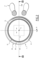
- This part 31 here has the shape of an open torus, arranged coaxially with the tubular box 21 of the chassis 20, being located at the end of the tubular box 21, which is axially opposite the ground.
- the toroidal shape of the part 31 is used to arrange the stabilizing member 30 laterally to the ball 10 and to bring this stabilizing member 30 into contact with the intermediate portion 13 of the ball 10 over a zone 32 of the part 31, which runs continuously all around the intermediate portion 13 of the ball 10.
- the zone 32 of the stabilizing member 30, which is in contact with the intermediate portion 13 of the ball 10 extends continuously over 360 degrees around the ball, which physically retains the ball 10 relative to the frame 20 in all horizontal directions.
- this zone 32 of the stabilizing member 30 prevents, by interference of contact with the intermediate portion 13 of the ball 10, that the position of the center 11 of the ball 10 can be modified relative to the frame 20.
- the center 11 of the ball 10 is thus immobilized relative to the frame 20 at ready functional clearances, linked in particular to the inherent flexibility of the wall of the ball 10.
- the zone 32 extends continuously over a lesser angular extent around the intermediate portion 13 of the ball 10, since this zone of the stabilizing member 30 extends continuously, in projection in a horizontal plane, over more than 180° around the ball 10.
- the sliding contact provided between the zone 32 of the stabilizing member 30 and the intermediate portion 13 of the ball 10 leaves the capacity for the ball 10 to rotate freely on itself around its center 11 relative to the chassis 20: this sliding contact results, in particular, from ad hoc characteristics of the part 31, in particular its geometric profile, its constituent material, etc.
- the apparatus 1 is designed to motorizedly drive the ball 10 in rotation around its center 11 relative to the chassis 20.
- the apparatus 1 comprises a mobile support member 40, which is only shown schematically in the figures 1 to 3 and of which multiple embodiments are conceivable.
- the mobile support member 40 is motorized and is adapted to support and rotate around the center 11 the lower portion 14 of the balloon 10, which in use, is pressed against the mobile support member 40, as clearly visible in the Figure 3 .
- the lower portion 14 of the ball 10 is pressed downwards against the movable support member 40 under the effect of the user U pressing on the upper portion 12 of the ball 10, this lower portion 14 having a tendency to slightly deform in a flexible manner by crushing for reasons similar to those indicated above with regard to the crushing of the upper portion 12 of the ball 10.
- the support of the lower portion 14 of the ball 10 on the movable support member 40 allows the transmission of movement from the movable member 40 to the lower portion 14 of the ball 10 and, thereby, to the entire ball 10.
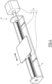
- the movable support member 40 comprises a plate 41, on which the lower portion 14 of the ball 10 rests and which is mounted movable on a base 42 of the movable support member 40, being guided, here exclusively, according to a rectilinear translational movement T relative to this base 42, and this by any appropriate guiding means.
- the base 42 is fixedly secured to the chassis 20 and thus forms a fixed part for the movable support member 40, compared to the plate 41 which forms a movable part thereof.
- the movable support member 40 comprises a motor unit 43 making it possible to control the movement, along the translation T, of the plate 41 relative to the base 42: in the example envisaged in Figure 4 , the drive unit 43 comprises an electric motor 44 whose output drives a worm screw 45 in rotation on itself, which is carried by the base 42 with interposition of bearings and which is screwed into a nut 46 securely connected to the plate 41. By actuating the electric motor 44, the screw 45 is screwed/unscrewed into the nut 46 while the latter is locked in rotation, which drives this nut 46 and, thereby, the plate 41 following the rectilinear translation T. More generally, it is understood that the mobile support member 40 illustrated in the Figure 4 corresponds to a motorized actuator with a translational linear output.
- the translational movement T of the movable support member 40 is transmitted to the lower portion 14 of the balloon 10, being transformed, by the presence of the stabilizing member 30, into a tilting movement B of the balloon 10 around a horizontal axis X40 passing through the center 11 of the balloon.
- This tilting movement B which is here the only movement with which the lower portion 14 of the balloon 14 is driven by the movable support member 40, is oriented correspondingly to the direction of the translational movement T, and this in the two possible opposite directions, as illustrated schematically in the Figure 3 .
- control unit 50 belonging to the device 1.
- This control unit 50 is shown schematically only at Figure 1 , being housed inside the chassis 20 without this arrangement being limiting.
- This control unit 50 makes it possible to control the actuation of the mobile support member 40.
- the control unit 50 controls the electric motor 44 so as to control the kinematic characteristics of the translational movement T and, thereby, those of the tilting movement B.
- the control unit 50 is typically of an electronic nature, including for example a microprocessor. More generally, the control unit 50 is connected, in a wired or wireless manner, to the mobile support member 40 for the purposes of controlling the latter, in particular its power supply, typically electricity.
- the user U mobilizes the joints and muscles of his lower limbs, his pelvis and his back in order to maintain his balance in a seated position on the upper portion 12 of the ball 10.
- the user U works in this way in a safe manner since the ball 10, even when driven with the tilting movement B, is retained by the stabilizing member 30, as explained above.
- the Figure 5 illustrates the situation where the user U is seated on the ball 10 so that the horizontal axis X40 extends substantially in the sagittal plane of the user U, the latter being observed from behind on the Figure 5 : the joint and muscular mobilization of the user U is then oriented in a mediolateral direction relative to the user, as indicated by the arrows ML on the Figure 5 .
- the situations respectively illustrated on the figures 3 And 5 in which the user U occupies respectively two different sitting positions which are at 90° to each other, are two configurations of use which are not limiting, but which are preferential in the sense that the latter can respectively allow a mobilization exclusively in the anteroposterior direction and a mobilization exclusively in the mediolateral direction.
- the chassis 20 is advantageously provided with markings or visual indicators, which are respectively associated with the two configurations of use and which allow the user U to easily position himself relative to the chassis and thus to place himself on the ball 10 in the chosen sitting position.
- markings or visual indicators which are respectively associated with the two configurations of use and which allow the user U to easily position himself relative to the chassis and thus to place himself on the ball 10 in the chosen sitting position.
- the angular amplitude of the tilting of the ball 10 relative to the aforementioned initial position, as well as the speed of this tilting and the number of back and forth movements can be adjusted using the control unit 50, for example by defining one or several pre-programmed sequences or, on the contrary, by authorizing random sequences.
- the user U can use the device 1 in positions other than the seated position.
- the user U stands, with one of his feet placed downwardly on the upper portion 12 of the ball 10 so that the ball supports the weight of a part of the body of the user U, while his other foot remains pressed directly on the ground.
- the device 1 can be used, for the purposes of bodily mobilization of the user U, according to multiple positions of the user, allowing the latter to support the weight of at least one part of his body on the upper portion 12 of the ball 10.
- the device 1 allows functional rehabilitation to be carried out on the user U, in passive mobilization or resistance, with control of the user's bodily mobilization.
- the device 1 allows the user U to work on their flexibility and muscular strength, to perform stretches, to improve their balance and to perform postural gymnastics.
- the bodily mobilization applied to the user U by the device 1 is carried out in a simple and effective manner, without apprehension on the part of the user, even if the latter is in a situation of reduced mobility or cognitive fragility.
- the apparatus 1 is equipped with an interface 60 which is connected to the control unit 50 for the purposes of activating and adjusting the latter.
- the interface 60 comprises control elements, which are respectively associated with the activation and adjustment parameters of the control unit 50 and which are operable by hand.
- the interface 60 comprises a display screen 61, which integrates the aforementioned control elements and which, in addition, makes it possible to display to the user U values relating to the operation of the apparatus 1, such as the duration of the current exercise, the kinematic characteristics of the movements applied to the ball 10 by the movable support member 40, the details of the sequence(s) in progress, etc.
- the display screen 61 thus allows feedback to the user U, allowing the latter to follow and control the bodily mobilization applied to him by the apparatus 1.
- the movable support member 40 of the device 1 may have other embodiments than that illustrated in Figure 4 .
- the Figure 6 watch, to As an alternative to the movable support member 40, a movable support member 140, which is functionally similar to the movable support member 40, but which is structurally different.
- the movable support member 140 comprises a conveyor belt 141 on which the lower part 14 of the ball 10 rests.
- the movable support member 40 also comprises rollers 142, around which the conveyor belt 141 is mounted by being movably linked to these rollers 142, as well as support shafts 143 on which the rollers 142 are respectively mounted for rotation around their central axis.
- the support shafts 143 are fixedly secured to the frame 20.
- the mobile support member 140 also comprises a drive unit 144, typically electrically powered, which makes it possible to drive at least one of the rollers 142 in rotation and, thereby, to control the movement of the conveyor belt 141 in a rectilinear translational movement, which is similar to the translational movement T described with respect to the Figure 4 and which, for convenience, is also referenced T on the Figure 6 .
- the conveyor belt 141 and the rollers 142 together form a movable part for the movable support member 140, which, with respect to the fixed part constituted by the support shafts 143 and with respect to the drive unit 144, is functionally similar to the plate 41 of the movable support member 40, with respect to the base 42 and the drive unit 43 of this movable support member 40.
- the movable support members 40 and 140 are not limiting but, on the contrary, illustrate the multiple possibilities of realization that the mobile support member belonging to the device 1 can take, in order to support the lower part 14 of the balloon 10 and to drive this lower portion of the balloon in rotation around the center 11 of the balloon 10 relative to the chassis 20, in particular following the tilting movement B around the horizontal axis X40, or even exclusively following this tilting movement B.
- the stabilizing member 30 of the apparatus 1 may have other embodiments than that illustrated in figures 1 to 4 .
- the Figure 7 shows, as an alternative to the stabilizing member 30, a stabilizing member 130, which is functionally similar to the stabilizing member 30, but which is structurally distinguished therefrom in several respects.
- the stabilizing member 130 comprises three rollers 131 respectively centered on axes X131.
- the rollers 131 are arranged laterally to the balloon 10, being in contact with the intermediate portion 13 of the balloon 10 on three respective distinct zones 132 of the rollers 131.
- the respective axes X131 of the rollers 131 extend, both horizontally and substantially parallel to tangents to the intermediate portion 13 of the balloon 10.
- the three zones 132 where the rollers 131 are in contact with the portion intermediate portion 13 of the balloon 10 are punctual, or almost punctual taking into account the deformation capacity of the wall of the balloon 10.
- the zones 132 of the rollers 131 are, in projection in a horizontal plane, regularly distributed around the intermediate portion 13 of the balloon 10 so as to constrain the center 11 of the balloon 10 in a fixed position. It is understood that, in variants not shown, the rollers 131 can be provided in a number other than three and can be produced in various forms of individual support elements belonging to the stabilizing member, provided that respective distinct zones of these support elements are in contact with the intermediate portion 13 of the balloon 10, being, in projection in a horizontal plane, sized and distributed around the balloon so as to keep the center 11 of the balloon substantially fixed relative to the chassis 20.
- each of the rollers 131 is provided, when the apparatus 1 is used, to be freely rotatable around its axis X131.
- the rollers 131 are, in use, freely movable relative to the chassis 20, namely, here, freely rotatable around their axis X131.
- FIG 8 shows, as an alternative embodiment to the mobile support members 40 and 140 for the apparatus 1, a mobile support member 240.
- the mobile support member 240 makes it possible, in particular from the translational movement T, to drive the lower portion 14 of the balloon 10 relative to the chassis 20 following the tilting movement B around a horizontal axis 240 similar to the horizontal axis X40.
- the mobile support member 240 also makes it possible to drive this lower portion 14 of the balloon 10 following a movement other than the tilting movement B, namely a tilting movement B' around a horizontal axis X240', which passes through the center 11 of the balloon 10 but which is distinct from the horizontal axis X240.
- the horizontal axes X240 and X240' are preferably perpendicular to each other, as in the example considered in figure 8 .
- the driving of the ball 10 following the tilting movement B' by the mobile support member 240 can be obtained from a translational movement T' of the mobile support member 240 relative to the chassis 20, in particular by integrating into the mobile support member 240 arrangements similar to those described above for the mobile support members 40 and 140 in connection with the translational movement T.
- the mobile support member 240 comprises two motorized actuators with output linear translational, which are individually similar to the linear actuator shown in the Figure 4 , but which are arranged “in series” with each other.
- the mobile support member 240 allows, in service, to drive the ball 10 in rotation around its center 11 relative to the chassis 20 according to two different distinct movements, namely the tilting movements B and B'.
- the respective kinematic characteristics of these two different movements are advantageously controlled by the control unit 50, adapted accordingly to control the movement of the mobile support member 240.
- a body mobilization apparatus 301 is shown, as an alternative embodiment to the apparatus 1 considered so far.
- This apparatus 301 comprises the balloon 10 described above, as well as a frame 320, a stabilizing member 330 and a movable support member 340, which are functionally similar to, respectively, the frame 20, the stabilizing member 30 or 130, and the movable support member 40 or 140 of the apparatus 1, but which are structurally different from the latter.
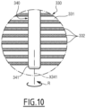
- the stabilizing member 330 is arranged below the lower part 14 of the balloon 10 and forms a bowl 331, which is fixedly integrated into the frame 320 and in the hollow of which the lower part 14 of the balloon 10 is brought into complementary contact.
- This bowl 331 makes it possible, in particular by its complementarity with the lower portion 14 of the balloon 10, to retain the balloon by contact, keeping the center 11 of the balloon 10 substantially fixed relative to the frame 320, while leaving the balloon 10 freely rotatable around its center 11 relative to the frame.
- the bowl 311 is provided in sliding contact with the balloon 10, the upper face of the bowl 311 being advantageously covered with sliding contact strips 332, as shown schematically in the Figure 10 .
- the mobile support member 340 is, for its part, produced in the form of a motorized roller 341 centered on a horizontal axis X341.
- the motorized roller 341 includes a motorization, which is typically electric and which is advantageously integrated inside the motorized roller. This motorization is capable of driving the motorized roller 341 in rotation on itself around its axis X341 relative to a fixed support of the motorized roller, this support being fixedly secured to the frame 320.
- the motorized roller 341 thus ensures the support of the lower portion 14 of the balloon 10 and, when it is driven in rotation according to the movement R, causes this lower portion of the ball to rotate around the center 11 of the ball relative to the chassis 320, in particular or even exclusively following a tilting movement, which is similar to the tilting movement B presented above and which, for convenience, is also referenced B on the figure 9 .
- a body mobilization apparatus 401 is shown, as an alternative embodiment to the apparatuses 1 and 301 considered so far.
- This apparatus 401 comprises a balloon 410, which, like the balloon 10, consists of an inflated flexible envelope, but which, unlike the balloon 10, is not spherical but has an elongated shape.
- the elongated shape of the balloon 410 is centered on an axis X410, along which this elongated shape extends in length and which, when the apparatus 401 is used, extends horizontally.
- the balloon 410 thus has a center 411, through which the horizontal axis X410 passes and which is located substantially midway between the opposite longitudinal ends of the balloon 410.
- the elongated shape of the balloon 410 has a contour, that is to say an external profile, which is circular and centered on the horizontal axis X410.
- This circular contour is found substantially at any point of the horizontal axis X410 along the ball 410 between its opposite longitudinal ends, except, where appropriate, locally at the level of these longitudinal ends.
- the diameter of the contour of the elongated shape of the balloon 410 is not constant in the current part of the balloon, connecting the opposite longitudinal ends of the balloon to each other.
- the balloon 410 thus advantageously includes a middle part 415, at which the center 411 is located along the horizontal axis X410, and two end parts 416 and 417, which are arranged on either side of the middle part 415 along the horizontal axis X410.
- the contour of the elongated shape of the balloon 410 has a diameter whose value is smaller than the diameter of the contour in the end parts 416 and 417: as a result, the balloon 410 generally has a peanut shape.
- the apparatus 401 also includes a frame 420 which is functionally similar to the frame 20 of the apparatus 1, but which is structurally different therefrom in that the frame 420 is adapted to the elongated shape of the balloon 410.
- the apparatus 401 also comprises a stabilizing member 430. Similar to the stabilizing member 30 of the apparatus 1, the stabilizing member 430 is carried by the chassis 420, being in service interposed between the latter and the balloon 410, and allows the balloon 410 to be retained by contact. More precisely, as for the stabilizing member 30, the stabilizing member 430 keeps the center 411 of the balloon 410 substantially fixed relative to the chassis 420, while allowing the balloon freedom of movement relative to the chassis 420. This freedom of movement is however less than that allowed by the stabilizing member 30, in the sense that, given the elongated shape of the balloon 410, the stabilizing member 430 leaves the balloon freely movable relative to the chassis 420 essentially, or even exclusively, following a tilting movement around the horizontal axis X410.
- This tilting movement is similar to the tilting movement B described previously so that, for convenience, it is also referenced B on the figures 11 And 12
- the specifications for the implementation of the stabilizing member 430 are not limiting and the various considerations previously developed regarding the multiple possible embodiments for the stabilizing member 30 apply, mutatis mutandis, to the stabilizing member 430.
- the apparatus 401 also comprises a movable support member 440 which is functionally similar to the movable support member 40 or 140 of the apparatus 1.
- the movable support member 410 is in particular designed to support the lower portion 414 of the ball 410, pressed, in particular at the level of the end parts 416 and 417, against it under the effect of the user U pressing on the upper portion 412 of the ball, and to drive this lower portion 414 and, thereby, the entire ball 410 following the tilting movement B, in particular from a translational movement which is similar to the translational movement T described previously for the movable support members 40 and 140.
- the movable support member 440 is for example structurally similar to the movable support members 40 and 140 detailed above.
- device 401 is similar to that of device 1.
- the user U is seated on the ball 410, more precisely on the middle part 415 of the latter, thus benefiting from an anteroposterior wedging effect of his pelvis by the terminal parts 416 and 417 of the ball, and this so that the horizontal axis X410 extends substantially in the sagittal plane of the user: by means of its driving by the mobile support member 440 and its retention guided by the stabilizing member 430, the ball 410 is moved according to the tilting movement B, which induces joint and muscular mobilization of the user U oriented in a mediolateral direction relative to the user.
- the apparatus 401 can be used in various other configurations.
Landscapes
- Health & Medical Sciences (AREA)
- General Health & Medical Sciences (AREA)
- Physical Education & Sports Medicine (AREA)
- Life Sciences & Earth Sciences (AREA)
- Biophysics (AREA)
- Engineering & Computer Science (AREA)
- Orthopedic Medicine & Surgery (AREA)
- Human Computer Interaction (AREA)
- Multimedia (AREA)
- Rehabilitation Therapy (AREA)
- Animal Behavior & Ethology (AREA)
- Public Health (AREA)
- Veterinary Medicine (AREA)
- Electromagnetism (AREA)
- Physics & Mathematics (AREA)
- Epidemiology (AREA)
- Pain & Pain Management (AREA)
- Rehabilitation Tools (AREA)
- Handcart (AREA)
- Invalid Beds And Related Equipment (AREA)
- Pivots And Pivotal Connections (AREA)
- Prostheses (AREA)
- Toys (AREA)
Claims (14)
- Körpermobilisationsgerät (1; 301; 401), umfassend:- einen Rahmen (20; 320; 420), der angepasst ist, um fest auf dem Boden zu stehen,- einen Ball (10; 410), der angepasst ist, um, während ein Benutzer (U) mindestens einen seiner Füße auf dem Boden hält, das Gewicht eines Körperteils des Benutzers zu tragen, der auf einem oberen Abschnitt (12; 412) des Balls abgestützt ist, - ein Stabilisierungselement (30; 130; 330; 430), das von dem Rahmen getragen wird und das konzipiert ist, um den Ballon durch Kontakt zu halten, um eine Mitte (11; 411) des Ballons in Bezug auf den Rahmen im Wesentlichen fixiert zu halten, während es den Ballon in Bezug auf den Rahmen zumindest gemäß einer ersten Kippbewegung (B) um eine erste horizontale Achse (X40; X240; X410), die durch die Mitte des Ballons verläuft, frei beweglich lässt, und - ein bewegliches Stützelement (40; 140; 240; 340; 440), das motorisiert ist und angepasst ist, um einen unteren Abschnitt (14; 414) des Ballons zu tragen, der unter der Wirkung der Abstützung des Benutzers auf dem oberen Abschnitt des Ballons nach unten gegen das bewegliche Stützelement gedrückt wird, und um diesen unteren Abschnitt des Ballons zumindest gemäß der ersten Kippbewegung (B) in Bezug auf den Rahmen mitzunehmen.
- Körpermobilisationsgerät nach Anspruch 1, wobei der Ballon (10) eine generell kugelförmige Form aufweist, die auf die Mitte (11) zentriert ist, wobei das Stabilisierungselement (30; 130; 330) konzipiert ist, um, während es die Mitte des Ballons in Bezug auf den Rahmen im Wesentlichen festhält, den Ballon frei um seine Mitte in Bezug auf den Rahmen drehbar zu lassen, und wobei das bewegliche Stützelement (40; 140; 240; 340) angepasst ist, um den unteren Abschnitt (14) des Ballons in eine Drehung um die Mitte des Ballons in Bezug auf den Rahmen zu versetzen.
- Körpermobilisationsgerät nach Anspruch 2, wobei das bewegliche Stützelement (40; 140; 340) konzipiert ist, um den unteren Abschnitt (14) des Ballons (10) in Bezug auf den Rahmen (20; 320) ausschließlich gemäß der ersten Kippbewegung (B) anzutreiben.
- Körpermobilisationsgerät nach Anspruch 2, wobei das bewegliche Stützelement (240) konzipiert ist, um zusätzlich zum Antreiben des unteren Abschnitts (14) des Ballons (10) in Bezug auf den Rahmen (20) gemäß der ersten Kippbewegung (B) den unteren Abschnitt des Ballons in Bezug auf den Rahmen gemäß einer zweiten Kippbewegung (B') um eine zweite horizontale Achse (X240') anzutreiben, die durch die Mitte (11)
des Ballons verläuft und die von der ersten horizontalen Achse (X240) getrennt ist. - Körpermobilisationsgerät nach Anspruch 4, wobei die zweite horizontale Achse (X240') senkrecht zu der ersten horizontalen Achse (X240) ist.
- Körpermobilisationsgerät nach Anspruch 1, wobei der Ballon (410) eine längliche Form aufweist, die sich in Längsrichtung entlang der ersten horizontalen Achse (X410) erstreckt und die in einem Schnitt senkrecht zu der ersten horizontalen Achse eine kreisförmige Kontur aufweist, die auf der ersten horizontalen Achse zentriert ist.
- Körpermobilisationsgerät nach Anspruch 6, wobei die kreisförmige Kontur einen Durchmesser aufweist, dessen Wert variabel ist, wenn der Ballon (410) entlang der ersten horizontalen Achse (X410) verläuft, wobei ein erster Wert in einem mittleren Teil (415) des Ballons vorliegt und ein zweiter Wert in jedem von zwei Endteilen (416, 417) des Ballons vorliegt, die auf beiden Seiten des mittleren Abschnitts entlang der ersten horizontalen Achse angeordnet sind, wobei der erste Wert kleiner ist als der zweite Wert.
- Körpermobilisationsgerät nach einem der vorherigen Ansprüche, wobei das bewegliche Stützelement (40; 140; 240; 340; 440) Folgendes umfasst:- eine Antriebseinheit (43; 144),- einen feststehenden Teil (42; 143), der fest mit dem Rahmen (20; 320) verbunden ist, und- einen beweglichen Teil (41; 141; 142), auf dem der untere Abschnitt (14) des Ballons (10; 410) ruht und der beweglich, insbesondere translatorisch oder rotatorisch, auf dem feststehenden Teil montiert ist, indem er von der Antriebseinheit in seiner Bewegung gesteuert wird.
- Körpermobilisationsgerät nach einem der vorherigen Ansprüche, wobei das Stabilisierungselement (30; 330; 430) im Gebrauch fest mit dem Rahmen (20; 320; 420) integriert ist und in Gleitkontakt mit dem Ballon (10; 410) ist.
- Körpermobilisationsgerät nach einem der Ansprüche 1 bis 8, wobei das Stabilisierungselement (130) im Gebrauch in Bezug auf den Rahmen (20) frei beweglich ist, indem es durch den Ballon (10) in Kontakt angetrieben wird.
- Körpermobilisationsgerät nach einem der vorherigen Ansprüche, wobei das Stabilisierungselement (30) seitlich von dem Ballon (10) angeordnet ist und einen Zwischenabschnitt (13) des Ballons an einem durchgehenden Bereich (32) des Stabilisierungselements berührt, der sich in der Projektion in einer horizontalen Ebene über mehr als 180° oder sogar 360° um den Ballon herum erstreckt.
- Körpermobilisationsgerät nach einem der Ansprüche 1 bis 10, wobei das Stabilisierungselement (130) seitlich von dem Ballon (10) angeordnet ist und einen Zwischenabschnitt (13) des Ballons an mehreren getrennten Bereichen (132) des Stabilisierungselements berührt, die in der Projektion in einer horizontalen Ebene bemessen und um den Ballon herum verteilt sind, sodass die Mitte (11) des Ballons in Bezug auf den Rahmen (20) im Wesentlichen feststehend gehalten wird.
- Körpermobilisationsgerät nach einem der Ansprüche 1 bis 10, wobei das Stabilisierungselement (330) unterhalb angeordnet ist und in komplementärem Kontakt mit dem unteren Abschnitt (14) des Ballons (10) ist.
- Körpermobilisationsgerät nach einem der vorherigen Ansprüche, wobei das Gerät (1; 401) eine Steuereinheit (50), die angepasst ist, um das bewegliche Stützelement (40; 340) in der Bewegung zu steuern, sowie eine Schnittstelle (60) umfasst, die angepasst ist, um die Steuereinheit zu aktivieren und einzustellen und um Werte anzuzeigen, die sich auf den Betrieb des Körpermobilisationsgeräts beziehen.
Applications Claiming Priority (2)
| Application Number | Priority Date | Filing Date | Title |
|---|---|---|---|
| FR2108806A FR3126187B1 (fr) | 2021-08-20 | 2021-08-20 | Appareil de mobilisation corporelle |
| PCT/EP2022/073164 WO2023021179A1 (fr) | 2021-08-20 | 2022-08-19 | Appareil de mobilisation corporelle |
Publications (2)
| Publication Number | Publication Date |
|---|---|
| EP4387748A1 EP4387748A1 (de) | 2024-06-26 |
| EP4387748B1 true EP4387748B1 (de) | 2025-06-11 |
Family
ID=78536338
Family Applications (1)
| Application Number | Title | Priority Date | Filing Date |
|---|---|---|---|
| EP22765898.6A Active EP4387748B1 (de) | 2021-08-20 | 2022-08-19 | Körpermobilisationsgerät |
Country Status (7)
| Country | Link |
|---|---|
| US (1) | US20240350858A1 (de) |
| EP (1) | EP4387748B1 (de) |
| CN (1) | CN117980041A (de) |
| ES (1) | ES3036246T3 (de) |
| FR (1) | FR3126187B1 (de) |
| PL (1) | PL4387748T3 (de) |
| WO (1) | WO2023021179A1 (de) |
Family Cites Families (9)
| Publication number | Priority date | Publication date | Assignee | Title |
|---|---|---|---|---|
| US6135928A (en) * | 1999-08-20 | 2000-10-24 | Butterfield; Anthony | Virtual reality equipment |
| US20040256532A1 (en) * | 2002-12-27 | 2004-12-23 | Hsin Lung Accessories Co., Ltd. | Ball positioning structure |
| US7713180B2 (en) * | 2003-11-19 | 2010-05-11 | Icon Ip, Inc. | Partially stabilized exercise device with valve mechanism |
| US7341548B2 (en) * | 2004-05-18 | 2008-03-11 | Charles J. Heitzman | Ball and frame exercising apparatus |
| US7118517B1 (en) * | 2005-04-11 | 2006-10-10 | Hale Thomas J | Exercise ball mounted for rotation |
| PH12013502642B1 (en) * | 2011-06-21 | 2017-11-10 | Brian Doyle | Device and method for performing exercises using a freely rotating ball |
| US10300329B2 (en) * | 2015-11-16 | 2019-05-28 | Tracy Byrd | Resilient exercise article |
| ITUA20162748A1 (it) * | 2016-04-20 | 2017-10-20 | B P Res Di Bergamelli Patrizio | Dispositivo per l’allenamento e la riabilitazione degli arti superiori ed inferiori |
| KR101935307B1 (ko) * | 2017-11-14 | 2019-01-04 | (주)멘퍼스 | 짐볼 운동기구 |
-
2021
- 2021-08-20 FR FR2108806A patent/FR3126187B1/fr active Active
-
2022
- 2022-08-19 CN CN202280061838.4A patent/CN117980041A/zh active Pending
- 2022-08-19 ES ES22765898T patent/ES3036246T3/es active Active
- 2022-08-19 US US18/684,833 patent/US20240350858A1/en active Pending
- 2022-08-19 EP EP22765898.6A patent/EP4387748B1/de active Active
- 2022-08-19 WO PCT/EP2022/073164 patent/WO2023021179A1/fr not_active Ceased
- 2022-08-19 PL PL22765898.6T patent/PL4387748T3/pl unknown
Also Published As
| Publication number | Publication date |
|---|---|
| US20240350858A1 (en) | 2024-10-24 |
| CN117980041A (zh) | 2024-05-03 |
| ES3036246T3 (en) | 2025-09-18 |
| EP4387748A1 (de) | 2024-06-26 |
| WO2023021179A1 (fr) | 2023-02-23 |
| FR3126187A1 (fr) | 2023-02-24 |
| PL4387748T3 (pl) | 2025-08-11 |
| FR3126187B1 (fr) | 2023-12-22 |
Similar Documents
| Publication | Publication Date | Title |
|---|---|---|
| EP1768637B1 (de) | Verfahren zur rehabilitierung motorischer störungen, insbesondere gehstörungen, bei patienten | |
| US6692451B2 (en) | Passive motion apparatus providing a controlled range of motion | |
| WO2007141429A1 (fr) | Appareil de mobilisation corporelle globale et utilisation d'un tel appareil | |
| CN105287123B (zh) | 一种康复轮椅 | |
| EP3846762B1 (de) | Vibrierender massagetisch | |
| KR101528562B1 (ko) | 회전근개 재활운동 장치 | |
| CN106619014A (zh) | 一种预防脊柱微变形的按摩椅 | |
| CN106580630A (zh) | 一种坐姿正脊按摩椅 | |
| FR3066397A1 (fr) | Dispositif d'entrainement a la marche | |
| EP4387748B1 (de) | Körpermobilisationsgerät | |
| CN107510924B (zh) | 一种多自由度的脚踝康复训练器 | |
| CN209108540U (zh) | 一种多功能肩袖损伤训练器 | |
| KR101559703B1 (ko) | 거꾸리 운동기 | |
| CN1872015B (zh) | 电动控制仰卧起坐按摩椅 | |
| CN115253179A (zh) | 一种脊柱外科腰椎锻炼装置及其使用方法 | |
| US7716758B2 (en) | Apparatus, bed and method for displacing a recumbent person to a sitting position | |
| FR2584922A1 (fr) | Table d'elongation du corps humain | |
| JP2019518585A (ja) | 筋肉活性化組立体システム及び方法 | |
| KR102707912B1 (ko) | 기립형 휠체어 | |
| CN206792627U (zh) | 一种坐姿正脊按摩椅 | |
| EP3122304A2 (de) | Selbstangetriebener rollstuhl für behinderte menschen mit einer neigbaren rückenlehne, die es dem benutzer ermöglicht, seine knöchel darauf abzulegen, wenn er in umgekehrter richtung sitzt | |
| KR101790441B1 (ko) | 보행보조기 겸용 휠체어 | |
| KR910005096B1 (ko) | 의자형 전신운동기 | |
| CN214435275U (zh) | 一种健身装置 | |
| WO2025144107A1 (fr) | Machine d'assistance a la priere |
Legal Events
| Date | Code | Title | Description |
|---|---|---|---|
| STAA | Information on the status of an ep patent application or granted ep patent |
Free format text: STATUS: UNKNOWN |
|
| STAA | Information on the status of an ep patent application or granted ep patent |
Free format text: STATUS: THE INTERNATIONAL PUBLICATION HAS BEEN MADE |
|
| PUAI | Public reference made under article 153(3) epc to a published international application that has entered the european phase |
Free format text: ORIGINAL CODE: 0009012 |
|
| STAA | Information on the status of an ep patent application or granted ep patent |
Free format text: STATUS: REQUEST FOR EXAMINATION WAS MADE |
|
| 17P | Request for examination filed |
Effective date: 20240220 |
|
| AK | Designated contracting states |
Kind code of ref document: A1 Designated state(s): AL AT BE BG CH CY CZ DE DK EE ES FI FR GB GR HR HU IE IS IT LI LT LU LV MC MK MT NL NO PL PT RO RS SE SI SK SM TR |
|
| DAV | Request for validation of the european patent (deleted) | ||
| DAX | Request for extension of the european patent (deleted) | ||
| GRAP | Despatch of communication of intention to grant a patent |
Free format text: ORIGINAL CODE: EPIDOSNIGR1 |
|
| STAA | Information on the status of an ep patent application or granted ep patent |
Free format text: STATUS: GRANT OF PATENT IS INTENDED |
|
| INTG | Intention to grant announced |
Effective date: 20250228 |
|
| GRAS | Grant fee paid |
Free format text: ORIGINAL CODE: EPIDOSNIGR3 |
|
| GRAA | (expected) grant |
Free format text: ORIGINAL CODE: 0009210 |
|
| STAA | Information on the status of an ep patent application or granted ep patent |
Free format text: STATUS: THE PATENT HAS BEEN GRANTED |
|
| AK | Designated contracting states |
Kind code of ref document: B1 Designated state(s): AL AT BE BG CH CY CZ DE DK EE ES FI FR GB GR HR HU IE IS IT LI LT LU LV MC MK MT NL NO PL PT RO RS SE SI SK SM TR |
|
| REG | Reference to a national code |
Ref country code: GB Ref legal event code: FG4D Free format text: NOT ENGLISH |
|
| REG | Reference to a national code |
Ref country code: CH Ref legal event code: EP |
|
| REG | Reference to a national code |
Ref country code: IE Ref legal event code: FG4D Free format text: LANGUAGE OF EP DOCUMENT: FRENCH |
|
| REG | Reference to a national code |
Ref country code: DE Ref legal event code: R096 Ref document number: 602022015878 Country of ref document: DE |
|
| REG | Reference to a national code |
Ref country code: ES Ref legal event code: FG2A Ref document number: 3036246 Country of ref document: ES Kind code of ref document: T3 Effective date: 20250918 |
|
| PG25 | Lapsed in a contracting state [announced via postgrant information from national office to epo] |
Ref country code: FI Free format text: LAPSE BECAUSE OF FAILURE TO SUBMIT A TRANSLATION OF THE DESCRIPTION OR TO PAY THE FEE WITHIN THE PRESCRIBED TIME-LIMIT Effective date: 20250611 |
|
| PGFP | Annual fee paid to national office [announced via postgrant information from national office to epo] |
Ref country code: ES Payment date: 20250908 Year of fee payment: 4 |
|
| PGFP | Annual fee paid to national office [announced via postgrant information from national office to epo] |
Ref country code: DE Payment date: 20250812 Year of fee payment: 4 |
|
| REG | Reference to a national code |
Ref country code: LT Ref legal event code: MG9D |
|
| PG25 | Lapsed in a contracting state [announced via postgrant information from national office to epo] |
Ref country code: GR Free format text: LAPSE BECAUSE OF FAILURE TO SUBMIT A TRANSLATION OF THE DESCRIPTION OR TO PAY THE FEE WITHIN THE PRESCRIBED TIME-LIMIT Effective date: 20250912 Ref country code: NO Free format text: LAPSE BECAUSE OF FAILURE TO SUBMIT A TRANSLATION OF THE DESCRIPTION OR TO PAY THE FEE WITHIN THE PRESCRIBED TIME-LIMIT Effective date: 20250911 |
|
| PGFP | Annual fee paid to national office [announced via postgrant information from national office to epo] |
Ref country code: IT Payment date: 20250901 Year of fee payment: 4 Ref country code: PL Payment date: 20250722 Year of fee payment: 4 |
|
| REG | Reference to a national code |
Ref country code: NL Ref legal event code: MP Effective date: 20250611 |
|
| PG25 | Lapsed in a contracting state [announced via postgrant information from national office to epo] |
Ref country code: BG Free format text: LAPSE BECAUSE OF FAILURE TO SUBMIT A TRANSLATION OF THE DESCRIPTION OR TO PAY THE FEE WITHIN THE PRESCRIBED TIME-LIMIT Effective date: 20250611 |
|
| PG25 | Lapsed in a contracting state [announced via postgrant information from national office to epo] |
Ref country code: HR Free format text: LAPSE BECAUSE OF FAILURE TO SUBMIT A TRANSLATION OF THE DESCRIPTION OR TO PAY THE FEE WITHIN THE PRESCRIBED TIME-LIMIT Effective date: 20250611 |
|
| PGFP | Annual fee paid to national office [announced via postgrant information from national office to epo] |
Ref country code: AT Payment date: 20251020 Year of fee payment: 4 Ref country code: FR Payment date: 20250710 Year of fee payment: 4 |
|
| PG25 | Lapsed in a contracting state [announced via postgrant information from national office to epo] |
Ref country code: RS Free format text: LAPSE BECAUSE OF FAILURE TO SUBMIT A TRANSLATION OF THE DESCRIPTION OR TO PAY THE FEE WITHIN THE PRESCRIBED TIME-LIMIT Effective date: 20250911 |
|
| PG25 | Lapsed in a contracting state [announced via postgrant information from national office to epo] |
Ref country code: LV Free format text: LAPSE BECAUSE OF FAILURE TO SUBMIT A TRANSLATION OF THE DESCRIPTION OR TO PAY THE FEE WITHIN THE PRESCRIBED TIME-LIMIT Effective date: 20250611 |
|
| PG25 | Lapsed in a contracting state [announced via postgrant information from national office to epo] |
Ref country code: NL Free format text: LAPSE BECAUSE OF FAILURE TO SUBMIT A TRANSLATION OF THE DESCRIPTION OR TO PAY THE FEE WITHIN THE PRESCRIBED TIME-LIMIT Effective date: 20250611 |
|
| PG25 | Lapsed in a contracting state [announced via postgrant information from national office to epo] |
Ref country code: PT Free format text: LAPSE BECAUSE OF FAILURE TO SUBMIT A TRANSLATION OF THE DESCRIPTION OR TO PAY THE FEE WITHIN THE PRESCRIBED TIME-LIMIT Effective date: 20251013 |
|
| REG | Reference to a national code |
Ref country code: AT Ref legal event code: MK05 Ref document number: 1801936 Country of ref document: AT Kind code of ref document: T Effective date: 20250611 |
|
| PG25 | Lapsed in a contracting state [announced via postgrant information from national office to epo] |
Ref country code: IS Free format text: LAPSE BECAUSE OF FAILURE TO SUBMIT A TRANSLATION OF THE DESCRIPTION OR TO PAY THE FEE WITHIN THE PRESCRIBED TIME-LIMIT Effective date: 20251011 |
|
| PG25 | Lapsed in a contracting state [announced via postgrant information from national office to epo] |
Ref country code: AT Free format text: LAPSE BECAUSE OF FAILURE TO SUBMIT A TRANSLATION OF THE DESCRIPTION OR TO PAY THE FEE WITHIN THE PRESCRIBED TIME-LIMIT Effective date: 20250611 Ref country code: SM Free format text: LAPSE BECAUSE OF FAILURE TO SUBMIT A TRANSLATION OF THE DESCRIPTION OR TO PAY THE FEE WITHIN THE PRESCRIBED TIME-LIMIT Effective date: 20250611 |
|
| PG25 | Lapsed in a contracting state [announced via postgrant information from national office to epo] |
Ref country code: CZ Free format text: LAPSE BECAUSE OF FAILURE TO SUBMIT A TRANSLATION OF THE DESCRIPTION OR TO PAY THE FEE WITHIN THE PRESCRIBED TIME-LIMIT Effective date: 20250611 |
|
| PG25 | Lapsed in a contracting state [announced via postgrant information from national office to epo] |
Ref country code: EE Free format text: LAPSE BECAUSE OF FAILURE TO SUBMIT A TRANSLATION OF THE DESCRIPTION OR TO PAY THE FEE WITHIN THE PRESCRIBED TIME-LIMIT Effective date: 20250611 |
|
| PG25 | Lapsed in a contracting state [announced via postgrant information from national office to epo] |
Ref country code: SK Free format text: LAPSE BECAUSE OF FAILURE TO SUBMIT A TRANSLATION OF THE DESCRIPTION OR TO PAY THE FEE WITHIN THE PRESCRIBED TIME-LIMIT Effective date: 20250611 |
|
| PG25 | Lapsed in a contracting state [announced via postgrant information from national office to epo] |
Ref country code: RO Free format text: LAPSE BECAUSE OF FAILURE TO SUBMIT A TRANSLATION OF THE DESCRIPTION OR TO PAY THE FEE WITHIN THE PRESCRIBED TIME-LIMIT Effective date: 20250611 |
|
| REG | Reference to a national code |
Ref country code: CH Ref legal event code: H13 Free format text: ST27 STATUS EVENT CODE: U-0-0-H10-H13 (AS PROVIDED BY THE NATIONAL OFFICE) Effective date: 20260324 |