EP4387181A2 - Ltf- und stf-übertragung für breitbandige 40 mhz mit mehr dc tönen in der drahtlosen kommunikation - Google Patents
Ltf- und stf-übertragung für breitbandige 40 mhz mit mehr dc tönen in der drahtlosen kommunikation Download PDFInfo
- Publication number
- EP4387181A2 EP4387181A2 EP23211682.2A EP23211682A EP4387181A2 EP 4387181 A2 EP4387181 A2 EP 4387181A2 EP 23211682 A EP23211682 A EP 23211682A EP 4387181 A2 EP4387181 A2 EP 4387181A2
- Authority
- EP
- European Patent Office
- Prior art keywords
- ltf
- subblock
- 80mhz
- optimized
- sequence
- Prior art date
- Legal status (The legal status is an assumption and is not a legal conclusion. Google has not performed a legal analysis and makes no representation as to the accuracy of the status listed.)
- Pending
Links
Images






Classifications
-
- H—ELECTRICITY
- H04—ELECTRIC COMMUNICATION TECHNIQUE
- H04L—TRANSMISSION OF DIGITAL INFORMATION, e.g. TELEGRAPHIC COMMUNICATION
- H04L27/00—Modulated-carrier systems
- H04L27/26—Systems using multi-frequency codes
- H04L27/2601—Multicarrier modulation systems
- H04L27/2602—Signal structure
- H04L27/261—Details of reference signals
- H04L27/2613—Structure of the reference signals
-
- H—ELECTRICITY
- H04—ELECTRIC COMMUNICATION TECHNIQUE
- H04L—TRANSMISSION OF DIGITAL INFORMATION, e.g. TELEGRAPHIC COMMUNICATION
- H04L27/00—Modulated-carrier systems
- H04L27/26—Systems using multi-frequency codes
- H04L27/2601—Multicarrier modulation systems
- H04L27/2602—Signal structure
- H04L27/261—Details of reference signals
- H04L27/2613—Structure of the reference signals
- H04L27/26132—Structure of the reference signals using repetition
-
- H—ELECTRICITY
- H04—ELECTRIC COMMUNICATION TECHNIQUE
- H04L—TRANSMISSION OF DIGITAL INFORMATION, e.g. TELEGRAPHIC COMMUNICATION
- H04L5/00—Arrangements affording multiple use of the transmission path
- H04L5/0001—Arrangements for dividing the transmission path
- H04L5/0003—Two-dimensional division
- H04L5/0005—Time-frequency
- H04L5/0007—Time-frequency the frequencies being orthogonal, e.g. OFDM(A) or DMT
-
- H—ELECTRICITY
- H04—ELECTRIC COMMUNICATION TECHNIQUE
- H04L—TRANSMISSION OF DIGITAL INFORMATION, e.g. TELEGRAPHIC COMMUNICATION
- H04L5/00—Arrangements affording multiple use of the transmission path
- H04L5/003—Arrangements for allocating sub-channels of the transmission path
- H04L5/0044—Allocation of payload; Allocation of data channels, e.g. PDSCH or PUSCH
-
- H—ELECTRICITY
- H04—ELECTRIC COMMUNICATION TECHNIQUE
- H04L—TRANSMISSION OF DIGITAL INFORMATION, e.g. TELEGRAPHIC COMMUNICATION
- H04L5/00—Arrangements affording multiple use of the transmission path
- H04L5/003—Arrangements for allocating sub-channels of the transmission path
- H04L5/0048—Allocation of pilot signals, i.e. of signals known to the receiver
-
- H—ELECTRICITY
- H04—ELECTRIC COMMUNICATION TECHNIQUE
- H04L—TRANSMISSION OF DIGITAL INFORMATION, e.g. TELEGRAPHIC COMMUNICATION
- H04L27/00—Modulated-carrier systems
- H04L27/26—Systems using multi-frequency codes
- H04L27/2601—Multicarrier modulation systems
- H04L27/2614—Peak power aspects
Definitions
- the present disclosure is generally related to wireless communications and, more particularly, to long training field (LTF) and short training field (STF) transmission for wide bandwidth 240MHz with more direct-current (DC) tones in wireless communications.
- LTF long training field
- STF short training field
- DC direct-current
- the present invention aims at providing schemes, concepts, designs, techniques, methods and apparatuses pertaining to LTF and STF transmission for wide bandwidth 240MHz with more DC tones in wireless communications. This is achieved by a method and an apparatus according to the independent claims.
- the dependent claims pertain to corresponding further developments and improvements.
- a 4x LTF sequence design (e.g., based on an IEEE 802.11be 80MHz subblock) may be utilized for wide bandwidths such as 240MHz.
- PAPR peak-to-average power ratio
- the claimed method involves generating either or both of an LTF and a STF of a physical-layer protocol data unit (PPDU) with a center 996-tone RU having more than a predetermined number of DC tones.
- the method may also involve performing a wireless communication in a wide bandwidth with the PPDU.
- PPDU physical-layer protocol data unit
- the claimed apparatus includes a transceiver and a processor coupled to the transceiver.
- the transceiver may be configured to transmit and receive wirelessly.
- the processor may be configured to generate either or both of an LTF and a STF of a physical-layer protocol data unit (PPDU) with a center 996-tone RU having more than a predetermined number of DC tones.
- the method may also involve performing a wireless communication in a wide bandwidth with the PPDU.
- PPDU physical-layer protocol data unit
- radio access technologies such as, Wi-Fi
- the proposed concepts, schemes and any variation(s)/derivative(s) thereof may be implemented in, for and by other types of radio access technologies, networks and network topologies such as, for example and without limitation, Bluetooth, ZigBee, 5 th Generation (5G)/New Radio (NR), Long-Term Evolution (LTE), LTE-Advanced, LTE-Advanced Pro, Internet-of-Things (IoT), Industrial IoT (IIoT) and narrowband IoT (NB-IoT).
- 5G 5 th Generation
- NR 5 th Generation
- LTE Long-Term Evolution
- LTE-Advanced LTE-Advanced
- LTE-Advanced Pro Internet-of-Things
- IoT Industrial IoT
- NB-IoT narrowband IoT
- Implementations in accordance with the present disclosure relate to various techniques, methods, schemes and/or solutions pertaining to LTF and STF transmission for wide bandwidth 240MHz with more DC tones in wireless communications.
- a number of possible solutions may be implemented separately or jointly. That is, although these possible solutions may be described below separately, two or more of these possible solutions may be implemented in one combination or another.
- a regular RU refers to a RU with tones that are continuous (e.g., adjacent to one another) and not interleaved, interlaced or otherwise distributed.
- a 26-tone regular RU may be interchangeably denoted as RU26 (or rRU26)
- a 52-tone regular RU may be interchangeably denoted as RU52 (or rRU52)
- a 106-tone regular RU may be interchangeably denoted as RU106 (or rRU106)
- a 242-tone regular RU may be interchangeably denoted as RU242 (or rRU242), and so on.
- an aggregate (26+52)-tone regular multi-RU may be interchangeably denoted as MRU78 (or rMRU78), an aggregate (26+106)-tone regular MRU may be interchangeably denoted as MRU132 (or rMRU132), and so on.
- a bandwidth of 20MHz may be interchangeably denoted as BW20 or BW20M
- a bandwidth of 40MHz may be interchangeably denoted as BW40 or BW40M
- a bandwidth of 80MHz may be interchangeably denoted as BW80 or BW80M
- a bandwidth of 160MHz may be interchangeably denoted as BW160 or BW160M
- a bandwidth of 240MHz may be interchangeably denoted as BW240 or BW240M
- a bandwidth of 320MHz may be interchangeably denoted as BW320 or BW320M
- a bandwidth of 480MHz may be interchangeably denoted as BW480 or BW480M
- a bandwidth of 640MHz may be interchangeably denoted as BW640 or
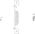
- FIG. 1 illustrates an example network environment 100 in which various solutions and schemes in accordance with the present disclosure may be implemented.
- FIG. 2 ⁇ FIG. 14 illustrate examples of implementation of various proposed schemes in network environment 100 in accordance with the present disclosure. The following description of various proposed schemes is provided with reference to FIG. 1 ⁇ FIG. 14 .
- network environment 100 may involve at least a station (STA) 110 communicating wirelessly with a STA 120.
- STA 110 and STA 120 may function as an access point (AP) STA or, alternatively, a non-AP STA.
- STA 110 and STA 120 may be associated with a basic service set (BSS) in accordance with one or more IEEE 802.11 standards (e.g., IEEE 802.11be and/or future-developed standards).
- BSS basic service set
- IEEE 802.11 e.g., IEEE 802.11be and/or future-developed standards.
- Each of STA 110 and STA 120 may be configured to communicate with each other by utilizing the LTF and STF transmission for wide bandwidth 240MHz with more DC tones in wireless communications in accordance with various proposed schemes described below.
- STA 110 and STA 120 may function as a "user" in the proposed schemes and examples described below. It is noteworthy that, while the various proposed schemes may be individually or separately described below, in actual implementations some or all of the proposed schemes may be utilized or otherwise implemented jointly. Of course, each of the proposed schemes may be utilized or otherwise implemented individually or separately.
- FIG. 2 illustrates an example scenario 200 in accordance with an implementation of the present disclosure.
- Scenario 200 may pertain to a RU tone plan for BW240 with five DC tones.
- the RU tone plan for BW240 may be comprised of three (left, middle and right) 80MHz subblocks (namely: first (1 st ) 80MHz subblock, second (2 nd ) 80MHz subblock and third (3 rd ) 80MHz subblock) with five DC tones in the center of the middle (or 2 nd ) 80MHz subblock.
- the table shows a list of RU/MUR types (in terms of number of tones in a given RU/MRU) and respective numbers of RU/MRUs transmittable in BW240.
- FIG. 3 illustrates an example design 300 in accordance with an implementation of the present disclosure.
- Design 300 may pertain to an optimized LTF sequence and PAPR performance for BW240.
- “0 5 " denotes five consecutive 0s
- “0 23” denotes twenty-three consecutive 0s.
- LTF 80MHz_subblock_left_4x denotes a left half of the 80MHz subblock base sequence with the 78.125kHz subcarrier spacing
- LTF 80MHz_subblock_right_4x denotes a right half of the 80MHz subblock base sequence with the 78.125kHz subcarrier spacing.
- the optimized coefficients are chosen to achieve the minimum PAPR of LTF sequences over all RU and MRU types/sizes in BW240 with the 4x UHR-LTF sequence under the proposed scheme. Referring to part (B) of FIG.
- the right-most column in the table shows the worst PAPR (in dB) of UHR-LTF for a number of spatial stream (Nss) ranging from one to eight for various combinations of RU/MRU types and various of RU/MRU sizes.
- the term "4x" refers to four times of the frequency of tones in the LTF relative to a legacy LTF.
- the subcarrier spacing in a 4x LTF sequence under the proposed schemes may be 78.125kHz (as opposed to 312.5kHz for legacy LTF).
- FIG. 4 illustrates an example design 400 in accordance with an implementation of the present disclosure.
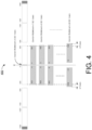
- Design 400 may pertain to a tone plan for a center 996-tone RU (RU996) with more DC tones in BW240.
- the number of DC tones in the center of the tone plan (namely, the center RU996) may be increased from five to seven, nine, and so on and up to a much larger number such as 23.
- the center RU996 may be designed by shifting a number of tones (e.g., shift by 1, 2, 3, ... , 9 tones) away from the center for both sides as shown in FIG. 4 .
- the first center RU996 from the top in FIG. 4 has tone indices ranging from -500 to -3 and from 3 to 500, and it has 5 DC tones with tone indices of -2, -1, 0, 1, 2.
- the second center RU996 from the top in FIG. 4 has tone indices ranging from -501 to -4 and from 4 to 501, and it has 7 DC tones with tone indices of -3, -2, -1, 0, 1, 2, 3.
- the third center RU996 from the top in FIG. 4 has tone indices ranging from -502 to -5 and from 5 to 502, and it has 9 DC tones with tone indices of -4, -3, -2, -1, 0, 1, 2, 3, 4.
- center RU996 shown in FIG. 4 have even more DC tones.
- the last center RU996 from the top (or the bottom center RU996) in FIG. 4 has tone indices ranging from -509 to -12 and from 12 to 509, and it has 23 DC tones with tone indices of -11, -10, -9, -8, -7, -6, -5, -4, -3, -2, -1, 0, 1, 2, 3, 4, 5, 6, 7, 8, 9, 10, 11.
- FIG. 4 may be seen as having a left portion and a right portion (with 23 DC tones therebetween) being shifted to the left by 9 tones and to the right be 9 tones, respectively.
- FIG. 4 shows an example that there may additionally be a right RU996 (e. g., with tone indices of [524:1021, 1027:1524]) and a left RU996 (e.g., with tone indices of [-1524:-1027, -1021:-524]) to the right and left sides of the center RU996 (e.g., with tone indices of [-500:-3, 3:500]).
- a right RU996 e. g., with tone indices of [524:1021, 1027:1524]
- a left RU996 e.g., with tone indices of [-1524:-1027, -1021:-524]
- FIG. 5 illustrates an example design 500 in accordance with an implementation of the present disclosure.
- Design 500 may pertain to a one-step LTF transmission operation for BW240 with more DC tones under a first option (Option-0).
- Option-0 a first option
- an optimized LTF sequence with five DC tones of design 300 may be reused or otherwise re-utilized.
- LTF 80MHz_subblock_left_4x denotes a left half of the 80MHz subblock base sequence with the 78.125kHz subcarrier spacing
- LTF 80MHz_subblock_right_4x denotes a right half of the 80MHz subblock base sequence with the 78.125kHz subcarrier spacing.
- tone indices of a center RU996 of the 5-DC tone plan may be mapped to corresponding tone positions or indices of a center RU996 of a UHR-LTF with more than a predetermined number of (e.g., more than five) DC tones (e.g., seven, nine, eleven or another number, such as twenty-three DC tones as shown in FIG. 5 ), and then the UHR-LTF may be transmitted (e.g., from STA 110 to STA 120, or vice versa).
- a predetermined number of (e.g., more than five) DC tones e.g., seven, nine, eleven or another number, such as twenty-three DC tones as shown in FIG. 5 .
- FIG. 6 illustrates an example design 600 in accordance with an implementation of the present disclosure.
- Design 600 may pertain to a two-step LTF transmission operation for BW240 with more DC tones under a second option (Option-1).
- Option-1 a same LTF sequence structure as a 5-DC tone plan may be used but with combining coefficients re-optimized. That is, in a first step, a 5-DC-tone center RU996 tone plan may be used to pick or select a segment of LTF sequence.
- the selected segment of LTF sequence may be mapped to the tone positions or indices of a center RU996 of a UHR-LTF with more than a predetermined number of (e.g., more than five) DC tones (e.g., seven, nine, eleven or another number, such as twenty-three DC tones as shown in FIG. 6 ), and then the UHR-LTF may be transmitted (e.g., from STA 110 to STA 120, or vice versa).
- the two-step operation may only be applied to the center RU996 or any MRU including a center RU996.
- LTF 80MHz_subblock_left_4x denotes a left half of the 80MHz subblock base sequence with the 78.125kHz subcarrier spacing
- LTF 80MHz_subblock_right_4x denotes a right half of the 80MHz subblock base sequence with the 78.125kHz subcarrier spacing.
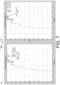
- FIG. 7 illustrates an example scenario 700 under a proposed scheme in accordance with the present disclosure.
- Scenario 700 may pertain to a PAPR performance comparison based on simulation results under Option-1.
- the curve labeled with "1" pertains to a 5-DC tone plan and the curve labeled with "2" pertains to a 23-DC tone plan.
- Part (A) of FIG. 7 shows a comparison of simulation results between a 5-DC tone plan and a 23-DC tone plan using the same LTF sequence as the 5-DC tone plan.
- the worst-case PAPR of the LTF sequence of the 23-DC tone plan is about 1.36dB higher (worse) than that of the 5-DC tone plan.
- Part (B) of FIG. 7 shows a comparison of simulation results between a 5-DC tone plan and a 23-DC tone plan using a re-optimized LTF sequence.
- the worst-case PAPR of the 23-DC tone plan is about the same as that of the 5-DC tone plan (i.e., no PAPR increase).
- FIG. 8 illustrates an example scenario 800 under a proposed scheme in accordance with the present disclosure.
- Scenario 800 may pertain to a PAPR performance comparison based on simulation results.
- the curve labeled with "1" pertains to a 5-DC tone plan
- the curve labeled with "2” pertains to a 23-DC tone plan with no change in pilot tone positions
- the curve labeled with "3" pertains to a 23-DC tone plan with pilot tone positions shifted (e.g., shifted left or right).
- the 23-DC tone plan with pilot tone positions shifted may achieve a better PAPR.
- the pilot tone positions of a center RU996 with more than a predetermined number of (e.g., more than five) DC tones may be shifted to achieve better PAPR performance for transmission in BW240.
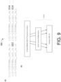
- FIG. 9 illustrates an example design 900 in accordance with an implementation of the present disclosure.
- Design 900 may pertain to a one-step LTF transmission operation for BW240 with more DC tones under a third option (Option-2).
- Option-2 a LTF sequence may be constructed and optimized as shown in FIG. 9 .
- LTF 80MHz_subblock_left_4x denotes a left half of the 80MHz subblock base sequence with the 78.125kHz subcarrier spacing
- LTF 80MHz_subblock_right_4x denotes a right half of the 80MHz subblock base sequence with the 78.125kHz subcarrier spacing.
- tone indices of a center RU996 of the optimized BW240 UHR-LTF sequence may be mapped to corresponding tone positions or indices of a center RU996 of a UHR-LTF with more than a predetermined number of (e.g., more than five) DC tones (e.g., seven, nine, eleven or another number, such as twenty-three DC tones as shown in FIG. 9 ), and then the UHR-LTF may be transmitted (e.g., from STA 110 to STA 120, or vice versa).
- a predetermined number of (e.g., more than five) DC tones e.g., seven, nine, eleven or another number, such as twenty-three DC tones as shown in FIG. 9 .
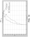
- FIG. 10 illustrates an example scenario 1000 under a proposed scheme in accordance with the present disclosure.
- Scenario 1000 may pertain to a PAPR performance comparison based on simulation results under Option-2.
- the curve labeled with "1” pertains to a 5-DC tone plan and the curve labeled with "2" pertains to a 23-DC tone plan with pilot tone positions shifted (e.g., shifted left or right).
- the worst-case PAPR of the 23-DC tone plan is about 1.15dB higher (worse) than that of the 5-DC tone plan.
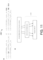
- FIG. 11 illustrates an example design 1100 in accordance with an implementation of the present disclosure.
- Design 1100 may pertain to a one-step LTF transmission operation for BW240 with more DC tones under a fourth option (Option-3).
- Option-3 a fourth option
- a LTF sequence may be constructed and optimized as shown in FIG. 11 .
- LTF 80MHz_subblock_left_4x denotes a left half of the 80MHz subblock base sequence with the 78.125kHz subcarrier spacing
- LTF 80MHz_subblock_right_4x denotes a right half of the 80MHz subblock base sequence with the 78.125kHz subcarrier spacing
- L9 denotes a sub-sequence of a 9-tone shift to the left-hand side (e.g., similar to the left portion of the bottom center RU996 in FIG. 4 being shifted to the left by 9 tones relative to the top center RU996 in FIG.
- R9 denotes a sub-sequence of a 9-tone shift to the right-hand side (e.g., similar to the right portion of the bottom center RU996 in FIG. 4 being shifted to the right by 9 tones relative to the top center RU996 in FIG. 4 ).
- Each of the sub-sequence L9 and R9 may be either all ones (1s) or any other sequence.
- tone indices of a center RU996 of the optimized BW240 UHR-LTF sequence may be mapped to corresponding tone positions or indices of a center RU996 of a UHR-LTF with more than a predetermined number of (e.g., more than five) DC tones (e.g., seven, nine, eleven or another number, such as twenty-three DC tones as shown in FIG. 11 ), and then the UHR-LTF may be transmitted (e.g., from STA 110 to STA 120, or vice versa).
- a predetermined number of (e.g., more than five) DC tones e.g., seven, nine, eleven or another number, such as twenty-three DC tones as shown in FIG. 11 .
- a STF sequence for BW240 with five DC tones may be provided.
- EHTS 80MHz_subblock_1x denotes one time of an extremely-high throughput (EHT) STF (EHT-STF) 80MHz subblock base sequence with the term "1x” referring to one time the frequency of tones in the STF relative to a legacy STF
- EHTS 80MHz_subblock_2x denotes two times (2x) of an EHT-STF 80MHz subblock sequence with the term "2x” referring to two times the frequency of tones in the STF relative to a legacy STF.
- the values of the EHT-STF sequence at indices [-8, -1016, -1032, -2040, 2040, 1032, 1016, 8] are zero (0).
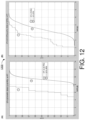
- Scenario 1200 may pertain to a PAPR performance comparison based on simulation results between a STF portion and a data portion of a PPDU in BW240 with five DC tones.
- the simulations were performed with MRU(2x996), MRU(2x996 + 484) and RU(3x996) with an assumption of > 68% of spectrum allocated for DL transmission.
- the data portion of the PPDU may be transmitted with binary phase-shift keying (BPSK) modulation.
- Part (A) of FIG. 12 shows an example of comparison in the context of a DL MU PPDU.
- Part (B) of FIG. 12 shows an example of comparison in the context of an UL TB PPDU.
- the curve labeled with "1" pertains to STF and the curve labeled with "2" pertains to data.
- the PAPR of the STF portion is much lower than the PAPR of the data portion of the PPDU, which is desirable.
- the optimized UHR-STF indicated above may be reused for a BW240 RU tone plan with more than a predetermined number of (e.g., more than five) DC tones (e.g., twenty-three DC tones).
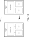
- FIG. 13 illustrates an example system 1300 having at least an example apparatus 1310 and an example apparatus 1320 in accordance with an implementation of the present disclosure.
- apparatus 1310 and apparatus 1320 may perform various functions to implement schemes, techniques, processes and methods described herein pertaining to LTF and STF transmission for wide bandwidth 240MHz with more DC tones in wireless communications, including the various schemes described above with respect to various proposed designs, concepts, schemes, systems and methods described above as well as processes described below.
- apparatus 1310 may be an example implementation of communication entity 110
- apparatus 1320 may be an example implementation of communication entity 120.
- Each of apparatus 1310 and apparatus 1320 may be a part of an electronic apparatus, which may be a STA or an AP, such as a portable or mobile apparatus, a wearable apparatus, a wireless communication apparatus or a computing apparatus.
- each of apparatus 1310 and apparatus 1320 may be implemented in a smartphone, a smart watch, a personal digital assistant, a digital camera, or a computing equipment such as a tablet computer, a laptop computer or a notebook computer.
- Each of apparatus 1310 and apparatus 1320 may also be a part of a machine type apparatus, which may be an IoT apparatus such as an immobile or a stationary apparatus, a home apparatus, a wire communication apparatus or a computing apparatus.
- each of apparatus 1310 and apparatus 1320 may be implemented in a smart thermostat, a smart fridge, a smart door lock, a wireless speaker or a home control center.
- apparatus 1310 and/or apparatus 1320 may be implemented in a network node, such as an AP in a WLAN.
- each of apparatus 1310 and apparatus 1320 may be implemented in the form of one or more integrated-circuit (IC) chips such as, for example and without limitation, one or more single-core processors, one or more multi-core processors, one or more reduced-instruction set computing (RISC) processors, or one or more complex-instruction-set-computing (CISC) processors.
- IC integrated-circuit
- RISC reduced-instruction set computing
- CISC complex-instruction-set-computing
- each of apparatus 1310 and apparatus 1320 may be implemented in or as a STA or an AP.
- Each of apparatus 1310 and apparatus 1320 may include at least some of those components shown in FIG. 13 such as a processor 1312 and a processor 1322, respectively, for example.
- Each of apparatus 1310 and apparatus 1320 may further include one or more other components not pertinent to the proposed scheme of the present disclosure (e.g., internal power supply, display device and/or user interface device), and, thus, such component(s) of apparatus 1310 and apparatus 1320 are neither shown in FIG. 13 nor described below in the interest of simplicity and brevity.
- other components e.g., internal power supply, display device and/or user interface device
- each of processor 1312 and processor 1322 may be implemented in the form of one or more single-core processors, one or more multi-core processors, one or more RISC processors or one or more CISC processors. That is, even though a singular term "a processor" is used herein to refer to processor 1312 and processor 1322, each of processor 1312 and processor 1322 may include multiple processors in some implementations and a single processor in other implementations in accordance with the present disclosure.
- each of processor 1312 and processor 1322 may be implemented in the form of hardware (and, optionally, firmware) with electronic components including, for example and without limitation, one or more transistors, one or more diodes, one or more capacitors, one or more resistors, one or more inductors, one or more memristors and/or one or more varactors that are configured and arranged to achieve specific purposes in accordance with the present disclosure.
- each of processor 1312 and processor 1322 is a special-purpose machine specifically designed, arranged and configured to perform specific tasks including those pertaining to LTF and STF transmission for wide bandwidth 240MHz with more DC tones in wireless communications in accordance with various implementations of the present disclosure.
- each of processor 1312 and processor 1322 may be configured with hardware components, or circuitry, implementing one, some or all of the examples described and illustrated herein.
- apparatus 1310 may also include a transceiver 1316 coupled to processor 1312.
- Transceiver 1316 may be capable of wirelessly transmitting and receiving data.
- apparatus 1320 may also include a transceiver 1326 coupled to processor 1322.
- Transceiver 1326 may include a transceiver capable of wirelessly transmitting and receiving data.
- apparatus 1310 may further include a memory 1314 coupled to processor 1312 and capable of being accessed by processor 1312 and storing data therein.
- apparatus 1320 may further include a memory 1324 coupled to processor 1322 and capable of being accessed by processor 1322 and storing data therein.
- RAM random-access memory
- DRAM dynamic RAM
- SRAM static RAM
- T-RAM thyristor RAM
- Z-RAM zero-capacitor RAM
- each of memory 1314 and memory 1324 may include a type of read-only memory (ROM) such as mask ROM, programmable ROM (PROM), erasable programmable ROM (EPROM) and/or electrically erasable programmable ROM (EEPROM).
- ROM read-only memory
- PROM programmable ROM
- EPROM erasable programmable ROM
- EEPROM electrically erasable programmable ROM
- each of memory 1314 and memory 1324 may include a type of non-volatile random-access memory (NVRAM) such as flash memory, solid-state memory, ferroelectric RAM (FeRAM), magnetoresistive RAM (MRAM) and/or phase-change memory.
- NVRAM non-volatile random-access memory
- Each of apparatus 1310 and apparatus 1320 may be a communication entity capable of communicating with each other using various proposed schemes in accordance with the present disclosure.
- a description of capabilities of apparatus 1310, as communication entity 110, and apparatus 1320, as communication entity 120, is provided below in the context of example process 1400.
- the example implementations described below are provided in the context of WLAN, the same may be implemented in other types of networks.
- the following description of example implementations pertains to a scenario in which apparatus 1310 functions as a transmitting device and apparatus 1320 functions as a receiving device, the same is also applicable to another scenario in which apparatus 1310 functions as a receiving device and apparatus 1320 functions as a transmitting device.
- FIG. 14 illustrates an example process 1400 in accordance with an implementation of the present disclosure.
- Process 1400 may represent an aspect of implementing various proposed designs, concepts, schemes, systems and methods described above. More specifically, process 1400 may represent an aspect of the proposed concepts and schemes pertaining to LTF and STF transmission for wide bandwidth 240MHz with more DC tones in wireless communications in accordance with the present disclosure.
- Process 1400 may include one or more operations, actions, or functions as illustrated by one or more of blocks 1410 and 1420. Although illustrated as discrete blocks, various blocks of process 1400 may be divided into additional blocks, combined into fewer blocks, or eliminated, depending on the desired implementation. Moreover, the blocks/sub-blocks of process 1400 may be executed in the order shown in FIG. 14 or, alternatively in a different order.
- Process 1400 may be implemented by or in apparatus 1310 and apparatus 1320 as well as any variations thereof. Solely for illustrative purposes and without limiting the scope, process 1400 is described below in the context of apparatus 1310 as communication entity 110 (e.g., a transmitting device whether a STA or an AP) and apparatus 1320 as communication entity 120 (e.g., a receiving device whether a STA or an AP) of a wireless network such as a WLAN in accordance with one or more of IEEE 802.11 standards. Process 1400 may begin at block 1410.
- communication entity 110 e.g., a transmitting device whether a STA or an AP
- apparatus 1320 as communication entity 120 (e.g., a receiving device whether a STA or an AP) of a wireless network such as a WLAN in accordance with one or more of IEEE 802.11 standards.
- Process 1400 may begin at block 1410.
- process 1400 may involve processor 1312 of apparatus 1310 generating either or both of an LTF and a STF of a PPDU with a center 996-tone RU having more than a predetermined number of (e.g., more than five) DC tones.
- Process 1400 may proceed from 1410 to 1420.
- process 1400 may involve processor 1312 performing, via transceiver 1316, a wireless communication in a wide bandwidth with the PPDU.
- process 1400 may involve processor 1312 generating either or both of the LTF and the STF of the PPDU using an 80MHz subblock base sequence such that either of the LTF and the STF is used in the wireless communication in a 240MHz bandwidth.
- process 1400 may involve processor 1312 generating the LTF using a one-step operation or a two-step operation.
- process 1400 may involve processor 1312 mapping tone indices of a center 996-tone RU (RU996) of an optimized LTF sequence to corresponding tone indices of a center RU996 of a UHR-LTF sequence with more than five DC tones.
- RU996 center 996-tone RU
- LTF 80MHz_subblock_left_4x denotes a left half of the 80MHz subblock base sequence with the 78.125kHz subcarrier spacing
- LTF 80MHz_subblock_right_4x denotes a right half of the 80MHz subblock base sequence with the 78.125kHz subcarrier spacing
- 0 5 denotes five consecutive 0s
- 0 23 denotes twenty-three consecutive 0s.
- LTF 80MHz_subblock_left_4x denotes a left half of the 80MHz subblock base sequence with the 78.125kHz subcarrier spacing
- LTF 80MHz_subblock_right_4x denotes a right half of the 80MHz subblock base sequence with the 78.125kHz subcarrier spacing
- 0 5 denotes five consecutive 0s
- 0 14 denotes fourteen consecutive 0s
- 0 23 denotes twenty-three consecutive 0s.
- LTF 80MHz_subblock_left_4x denotes a left half of the 80MHz subblock base sequence with the 78.125kHz subcarrier spacing
- LTF 80MHz_subblock_right_4x denotes a right half of the 80MHz subblock base sequence with the 78.125kHz subcarrier spacing
- 0 5 denotes five consecutive 0s
- 0 14 denotes fourteen consecutive 0s.
- process 1400 may involve processor 1312 performing certain operations. For instance, process 1400 may involve processor 1312 selecting a segment of an optimized LTF sequence using a five-DC-tone center RU996 tone plan. Additionally, process 1400 may involve processor 1312 mapping the selected segment of the optimized LTF sequence to tone indices of a center RU996 of a UHR-LTF sequence with more than five DC tones.
- LTF 80MHz_subblock_left_4x denotes a left half of the 80MHz subblock base sequence with the 78.125kHz subcarrier spacing
- LTF 80MHz_subblock_right_4x denotes a right half of the 80MHz subblock base sequence with the 78.125kHz subcarrier spacing
- 0 5 denotes five consecutive 0s
- 0 23 denotes twenty-three consecutive 0s.
- process 1400 may involve processor 1312 generating an optimized STF sequence for a DL MU PPDU or an UL TB PPDU using a combination of optimized coefficients.
- the optimized STF sequence [c(1) * EHTS 80MHz_subblock_1x , 0, c(2) * EHTS 80MHz_subblock_1x , 0, c(3) * EHTS 80MHz_subblock_1x ] * (1 + j) / sqrt(2)
- EHTS 80MHz_subblock_1x denotes one time of an EHT-STF 80MHz subblock base sequence
- EHTS 80MHz_subblock_2x denotes two times of the EHT-STF 80MHz subblock base sequence.
- any two components so associated can also be viewed as being “operably connected”, or “operably coupled”, to each other to achieve the desired functionality, and any two components capable of being so associated can also be viewed as being “operably couplable”, to each other to achieve the desired functionality.
- operably couplable include but are not limited to physically mateable and/or physically interacting components and/or wirelessly interactable and/or wirelessly interacting components and/or logically interacting and/or logically interactable components.
Landscapes
- Engineering & Computer Science (AREA)
- Signal Processing (AREA)
- Computer Networks & Wireless Communication (AREA)
- Mobile Radio Communication Systems (AREA)
- Telephonic Communication Services (AREA)
Applications Claiming Priority (2)
| Application Number | Priority Date | Filing Date | Title |
|---|---|---|---|
| US202263384785P | 2022-11-23 | 2022-11-23 | |
| US18/515,311 US12452118B2 (en) | 2022-11-23 | 2023-11-21 | LTF and STF transmission for wide bandwidth 240MHz with more DC tones in wireless communications |
Publications (2)
| Publication Number | Publication Date |
|---|---|
| EP4387181A2 true EP4387181A2 (de) | 2024-06-19 |
| EP4387181A3 EP4387181A3 (de) | 2024-08-14 |
Family
ID=88965193
Family Applications (1)
| Application Number | Title | Priority Date | Filing Date |
|---|---|---|---|
| EP23211682.2A Pending EP4387181A3 (de) | 2022-11-23 | 2023-11-23 | Ltf- und stf-übertragung für breitbandige 40 mhz mit mehr dc tönen in der drahtlosen kommunikation |
Country Status (3)
| Country | Link |
|---|---|
| US (1) | US20250385821A1 (de) |
| EP (1) | EP4387181A3 (de) |
| TW (1) | TW202429937A (de) |
Family Cites Families (3)
| Publication number | Priority date | Publication date | Assignee | Title |
|---|---|---|---|---|
| US12095684B2 (en) * | 2019-02-19 | 2024-09-17 | Lg Electronics Inc. | Method and apparatus for receiving EHT PPDU in wireless LAN system |
| WO2021251591A1 (ko) * | 2020-06-09 | 2021-12-16 | 엘지전자 주식회사 | 320mhz를 위한 4x ltf 시퀀스 |
| WO2024055989A1 (en) * | 2022-09-14 | 2024-03-21 | Mediatek Inc. | 4x ltf sequence design for wide bandwidths in wireless communications |
-
2023
- 2023-11-23 EP EP23211682.2A patent/EP4387181A3/de active Pending
- 2023-11-23 TW TW112145283A patent/TW202429937A/zh unknown
-
2025
- 2025-09-10 US US19/324,145 patent/US20250385821A1/en active Pending
Also Published As
| Publication number | Publication date |
|---|---|
| TW202429937A (zh) | 2024-07-16 |
| EP4387181A3 (de) | 2024-08-14 |
| US20250385821A1 (en) | 2025-12-18 |
Similar Documents
| Publication | Publication Date | Title |
|---|---|---|
| CN114071469B (zh) | 利用音调分散的资源单元的通信方法以及通信装置 | |
| EP4047894A1 (de) | Eht-ltf-sequenzentwurf für verteilte ton-ressourceneinheiten mit papr-reduktion | |
| US11825493B2 (en) | Resource unit allocation subfield designs for trigger-based and self-contained signaling in extreme high-throughput systems | |
| US20260012309A1 (en) | Pilot Tone Design For Distributed-Tone Resource Units In 6GHz Low-Power Indoor Systems | |
| EP3879740B1 (de) | Verfahren zur verarbeitung von restbits für das proportionale rundlauf-verfahrens-parsing von ressourceneinheiten in systemen mit extrem hohem durchsatz | |
| US20240097820A1 (en) | Performance Enhancement Of RU Duplication With Predefined Interleaving Patterns In Wireless Communications | |
| US11696270B2 (en) | Efficient resource unit allocation signaling in extreme-high-throughput wireless communications | |
| WO2024055989A1 (en) | 4x ltf sequence design for wide bandwidths in wireless communications | |
| EP4319071A1 (de) | Papr-reduktion zur duplizierung einer ressourceneinheit und tonwiederholung | |
| US12452006B2 (en) | Global CSD index assignment for distributed-tone resource unit transmissions | |
| US12452118B2 (en) | LTF and STF transmission for wide bandwidth 240MHz with more DC tones in wireless communications | |
| EP4340309A1 (de) | Stf-sequenzdesign für breite bandbreiten in der drahtlosen kommunikation | |
| EP3937448A1 (de) | Doppelte trägermodulation mit niedrigem papr für bpsk in drahtloser kommunikation | |
| US12477530B2 (en) | Scalable waveform and numerology designs for next-generation WLAN in 60GHz band | |
| EP4362375A1 (de) | Center-ru996-tonplanentwürfe für breitbandige 40 mhz in der drahtlosen kommunikation | |
| US20210068128A1 (en) | Enhanced PUCCH Format 0 And Format 1 Design For New Radio Unlicensed Spectrum Operation | |
| US20250385821A1 (en) | LTF And STF Transmission For Wide Bandwidth 240MHz With More DC Tones In Wireless Communications | |
| WO2026103920A1 (en) | Transmission of 60mhz dru on frequency subblocks of wider bandwidths in wireless communications | |
| US20240364391A1 (en) | MU-MIMO Transmission With Mixed Bandwidths And Unequal Modulations In Wireless Communications | |
| WO2024251277A1 (en) | Multiple mru transmission methods for next-generation wlan systems | |
| WO2024160248A1 (en) | Sub-resource unit based adaptive modulation schemes in wireless communications | |
| CN117858240A (zh) | 与fd-a-ppdu相关的无线通信方法以及相关装置 |
Legal Events
| Date | Code | Title | Description |
|---|---|---|---|
| PUAI | Public reference made under article 153(3) epc to a published international application that has entered the european phase |
Free format text: ORIGINAL CODE: 0009012 |
|
| STAA | Information on the status of an ep patent application or granted ep patent |
Free format text: STATUS: THE APPLICATION HAS BEEN PUBLISHED |
|
| AK | Designated contracting states |
Kind code of ref document: A2 Designated state(s): AL AT BE BG CH CY CZ DE DK EE ES FI FR GB GR HR HU IE IS IT LI LT LU LV MC ME MK MT NL NO PL PT RO RS SE SI SK SM TR |
|
| PUAL | Search report despatched |
Free format text: ORIGINAL CODE: 0009013 |
|
| AK | Designated contracting states |
Kind code of ref document: A3 Designated state(s): AL AT BE BG CH CY CZ DE DK EE ES FI FR GB GR HR HU IE IS IT LI LT LU LV MC ME MK MT NL NO PL PT RO RS SE SI SK SM TR |
|
| RIC1 | Information provided on ipc code assigned before grant |
Ipc: H04L 5/00 20060101ALI20240709BHEP Ipc: H04L 27/26 20060101AFI20240709BHEP |
|
| STAA | Information on the status of an ep patent application or granted ep patent |
Free format text: STATUS: REQUEST FOR EXAMINATION WAS MADE |
|
| 17P | Request for examination filed |
Effective date: 20250128 |