EP4387082A1 - Motor flying start using field weakening control - Google Patents
Motor flying start using field weakening control Download PDFInfo
- Publication number
- EP4387082A1 EP4387082A1 EP23214242.2A EP23214242A EP4387082A1 EP 4387082 A1 EP4387082 A1 EP 4387082A1 EP 23214242 A EP23214242 A EP 23214242A EP 4387082 A1 EP4387082 A1 EP 4387082A1
- Authority
- EP
- European Patent Office
- Prior art keywords
- axis current
- current reference
- motor
- power conversion
- conversion system
- Prior art date
- Legal status (The legal status is an assumption and is not a legal conclusion. Google has not performed a legal analysis and makes no representation as to the accuracy of the status listed.)
- Pending
Links
Images


Classifications
-
- H—ELECTRICITY
- H02—GENERATION; CONVERSION OR DISTRIBUTION OF ELECTRIC POWER
- H02P—CONTROL OR REGULATION OF ELECTRIC MOTORS, ELECTRIC GENERATORS OR DYNAMO-ELECTRIC CONVERTERS; CONTROLLING TRANSFORMERS, REACTORS OR CHOKE COILS
- H02P21/00—Arrangements or methods for the control of electric machines by vector control, e.g. by control of field orientation
- H02P21/0085—Arrangements or methods for the control of electric machines by vector control, e.g. by control of field orientation specially adapted for high speeds, e.g. above nominal speed
- H02P21/0089—Arrangements or methods for the control of electric machines by vector control, e.g. by control of field orientation specially adapted for high speeds, e.g. above nominal speed using field weakening
-
- H—ELECTRICITY
- H02—GENERATION; CONVERSION OR DISTRIBUTION OF ELECTRIC POWER
- H02P—CONTROL OR REGULATION OF ELECTRIC MOTORS, ELECTRIC GENERATORS OR DYNAMO-ELECTRIC CONVERTERS; CONTROLLING TRANSFORMERS, REACTORS OR CHOKE COILS
- H02P27/00—Arrangements or methods for the control of AC motors characterised by the kind of supply voltage
- H02P27/04—Arrangements or methods for the control of AC motors characterised by the kind of supply voltage using variable-frequency supply voltage, e.g. inverter or converter supply voltage
- H02P27/06—Arrangements or methods for the control of AC motors characterised by the kind of supply voltage using variable-frequency supply voltage, e.g. inverter or converter supply voltage using DC to AC converters or inverters
-
- H—ELECTRICITY
- H02—GENERATION; CONVERSION OR DISTRIBUTION OF ELECTRIC POWER
- H02P—CONTROL OR REGULATION OF ELECTRIC MOTORS, ELECTRIC GENERATORS OR DYNAMO-ELECTRIC CONVERTERS; CONTROLLING TRANSFORMERS, REACTORS OR CHOKE COILS
- H02P1/00—Arrangements for starting electric motors or dynamo-electric converters
- H02P1/02—Details of starting control
- H02P1/029—Restarting, e.g. after power failure
-
- H—ELECTRICITY
- H02—GENERATION; CONVERSION OR DISTRIBUTION OF ELECTRIC POWER
- H02P—CONTROL OR REGULATION OF ELECTRIC MOTORS, ELECTRIC GENERATORS OR DYNAMO-ELECTRIC CONVERTERS; CONTROLLING TRANSFORMERS, REACTORS OR CHOKE COILS
- H02P21/00—Arrangements or methods for the control of electric machines by vector control, e.g. by control of field orientation
- H02P21/14—Estimation or adaptation of machine parameters, e.g. flux, current or voltage
- H02P21/141—Flux estimation
-
- H—ELECTRICITY
- H02—GENERATION; CONVERSION OR DISTRIBUTION OF ELECTRIC POWER
- H02P—CONTROL OR REGULATION OF ELECTRIC MOTORS, ELECTRIC GENERATORS OR DYNAMO-ELECTRIC CONVERTERS; CONTROLLING TRANSFORMERS, REACTORS OR CHOKE COILS
- H02P21/00—Arrangements or methods for the control of electric machines by vector control, e.g. by control of field orientation
- H02P21/14—Estimation or adaptation of machine parameters, e.g. flux, current or voltage
- H02P21/18—Estimation of position or speed
-
- H—ELECTRICITY
- H02—GENERATION; CONVERSION OR DISTRIBUTION OF ELECTRIC POWER
- H02P—CONTROL OR REGULATION OF ELECTRIC MOTORS, ELECTRIC GENERATORS OR DYNAMO-ELECTRIC CONVERTERS; CONTROLLING TRANSFORMERS, REACTORS OR CHOKE COILS
- H02P21/00—Arrangements or methods for the control of electric machines by vector control, e.g. by control of field orientation
- H02P21/22—Current control, e.g. using a current control loop
-
- H—ELECTRICITY
- H02—GENERATION; CONVERSION OR DISTRIBUTION OF ELECTRIC POWER
- H02P—CONTROL OR REGULATION OF ELECTRIC MOTORS, ELECTRIC GENERATORS OR DYNAMO-ELECTRIC CONVERTERS; CONTROLLING TRANSFORMERS, REACTORS OR CHOKE COILS
- H02P21/00—Arrangements or methods for the control of electric machines by vector control, e.g. by control of field orientation
- H02P21/24—Vector control not involving the use of rotor position or rotor speed sensors
- H02P21/26—Rotor flux based control
-
- H—ELECTRICITY
- H02—GENERATION; CONVERSION OR DISTRIBUTION OF ELECTRIC POWER
- H02P—CONTROL OR REGULATION OF ELECTRIC MOTORS, ELECTRIC GENERATORS OR DYNAMO-ELECTRIC CONVERTERS; CONTROLLING TRANSFORMERS, REACTORS OR CHOKE COILS
- H02P21/00—Arrangements or methods for the control of electric machines by vector control, e.g. by control of field orientation
- H02P21/34—Arrangements for starting
-
- H—ELECTRICITY
- H02—GENERATION; CONVERSION OR DISTRIBUTION OF ELECTRIC POWER
- H02P—CONTROL OR REGULATION OF ELECTRIC MOTORS, ELECTRIC GENERATORS OR DYNAMO-ELECTRIC CONVERTERS; CONTROLLING TRANSFORMERS, REACTORS OR CHOKE COILS
- H02P25/00—Arrangements or methods for the control of AC motors characterised by the kind of AC motor or by structural details
- H02P25/02—Arrangements or methods for the control of AC motors characterised by the kind of AC motor or by structural details characterised by the kind of motor
- H02P25/022—Synchronous motors
- H02P25/024—Synchronous motors controlled by supply frequency
-
- H—ELECTRICITY
- H02—GENERATION; CONVERSION OR DISTRIBUTION OF ELECTRIC POWER
- H02P—CONTROL OR REGULATION OF ELECTRIC MOTORS, ELECTRIC GENERATORS OR DYNAMO-ELECTRIC CONVERTERS; CONTROLLING TRANSFORMERS, REACTORS OR CHOKE COILS
- H02P25/00—Arrangements or methods for the control of AC motors characterised by the kind of AC motor or by structural details
- H02P25/02—Arrangements or methods for the control of AC motors characterised by the kind of AC motor or by structural details characterised by the kind of motor
- H02P25/08—Reluctance motors
- H02P25/092—Converters specially adapted for controlling reluctance motors
-
- H—ELECTRICITY
- H02—GENERATION; CONVERSION OR DISTRIBUTION OF ELECTRIC POWER
- H02P—CONTROL OR REGULATION OF ELECTRIC MOTORS, ELECTRIC GENERATORS OR DYNAMO-ELECTRIC CONVERTERS; CONTROLLING TRANSFORMERS, REACTORS OR CHOKE COILS
- H02P2201/00—Indexing scheme relating to controlling arrangements characterised by the converter used
- H02P2201/01—AC-AC converter stage controlled to provide a defined AC voltage
-
- H—ELECTRICITY
- H02—GENERATION; CONVERSION OR DISTRIBUTION OF ELECTRIC POWER
- H02P—CONTROL OR REGULATION OF ELECTRIC MOTORS, ELECTRIC GENERATORS OR DYNAMO-ELECTRIC CONVERTERS; CONTROLLING TRANSFORMERS, REACTORS OR CHOKE COILS
- H02P2207/00—Indexing scheme relating to controlling arrangements characterised by the type of motor
- H02P2207/01—Asynchronous machines
Definitions
- the subject matter disclosed herein relates to power converters.
- a power conversion system includes an inverter configured to convert DC power to AC power to drive a motor, and a controller, configured to operate the inverter to perform a flying start operation using field weakening control responsive to a motor speed of the motor exceeding a non-zero threshold at startup of the power conversion system.
- a method in another aspect, includes measuring a motor speed of a motor, responsive to startup of a power conversion system, and performing a flying start operation using field weakening control to control the motor responsive to the motor speed exceeding a non-zero threshold at startup of the power conversion system.
- a non-transitory computer readable medium has computer executable instructions which, when executed by a processor, cause the processor to measure a motor speed of a motor, responsive to startup of a power conversion system, and perform a flying start operation using field weakening control to control the motor responsive to the motor speed exceeding a non-zero threshold at startup of the power conversion system.
- Described examples provide solutions as methods, power conversion systems, and computer readable mediums for implementing flying start of a rotating motor by field weakening control to control the motor in response to the motor speed exceeding the rated speed or other non-zero threshold at startup of the power conversion system.
- Example implementations mitigate or avoid unwanted overvoltage or overcurrent trips without adding components or cost to motor drive power conversion systems to provide a solution that can help enable reliable flying start operation for motors spinning at high speeds upon startup of the motor drive.
- Flying start capabilities can be useful in a variety of applications, such as motor drives configured to drive outdoor fans or pumps in wells.
- the blades of a driven fan or pump may rotate when the drive is turned off, due to ambient wind near an outdoor fan or flow of a pumped fluid in a well.
- Starting a drive when the rotor of the driven motor is rotating is referred to as a flying start and may result in high current spikes in the drive.
- the rotor shaft speed and position e.g., angle
- volts hertz matching is performed to match the drive output voltage and speed to the respective CEMF and rotor rotation to mitigate or avoid high current spikes when active driving of the rotating motor begins.
- FIG. 1 shows an example electrical system with a motor drive power conversion system 100 that converts electrical power from an external power source 102 to drive a motor load 104.
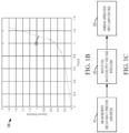
- FIG. 1C shows three flying start states 191, 192, and 193 implemented by the motor drive power conversion system 100 in one example, including a first state 191 for measurement including obtaining motor shaft position and speed, a second state 192 for matching volts and hertz to match the drive output voltage and frequency with motor CEMF and speed, and a third state 193 for normal operation with open loop control.
- the motor 104 is an induction motor.
- the motor 104 is a synchronous reluctance motor.
- the motor drive power conversion system 100 is part of a fan system, where the motor 104 drives a fan, such as for environmental control of a building (e.g., heating and/or air conditioning).
- the motor drive power conversion system 100 is part of a pump system, in which the motor 104 drives a pump that pumps a fluid in an industrial facility or at a well or mine.
- the system 100 in one example implements intelligent flying starts by field weakening control in responsive to the motor speed exceeding a non-zero threshold at startup of the power conversion system 100, and the system ramps the drive output voltage and frequency to match the CEMF of the rotating motor and eventually resumes or starts normal operation without causing current spikes or tripping the drive.
- the example flying start apparatus and techniques can be used to start a rotating motor and resume normal operation as quick as possible, with a minimal impact on load or speed for a variety of applications such as fan/pump systems.
- the motor drive power conversion system 100 receives single or multiphase AC input power from the external power source 102.
- the illustrated example receives a three-phase input. In other examples, single phase or other multiphase embodiments are possible.
- the motor drive 100 converts input power from the source 102 to deliver output power to drive the motor load 104.
- the motor drive 100 includes a three-phase input filter circuit 120, such as an LC or LCL, filter.
- the motor drive 100 also includes a rectifier 130, a DC bus or DC link circuit 140, and an output inverter 150.
- the rectifier 130 and the inverter 150 are operated by a controller 160.
- the controller 160 includes a processor 162, an electronic memory 164 or other non-transitory computer readable medium that stores data and program instructions, as well as a rectifier controller 132 and an inverter controller 152.
- the processor 162 in one example includes an internal electronic memory (not shown) that stores data values and provides a non-transitory computer-readable medium that stores computer-executable instructions which, when executed by the processor 162, cause the processor 162 to implement the various functions and features described herein.
- the memory 164 is external to the processor 162 and the memory 164 stores data values and provides a non-transitory computer-readable medium that stores computer-executable instructions which, when executed by the processor 162, cause the processor 162 to implement the various functions and features described herein.
- the controller 160 and the components thereof may be implemented as any suitable hardware, processor-executed software, processor-executed firmware, logic, and/or combinations thereof wherein the illustrated controller 160 can be implemented in processor-executed software or firmware providing various control functions by which the controller 160 receives feedback and/or input signals and/or values (e.g., sctpoint(s)) and provides rectifier and inverter switching control signals 134 and 154 to operate switching devices S1-S6 of the rectifier 130 and switches S7-S12 of the inverter 150 to convert input power for providing AC output power to drive the motor 104.
- feedback and/or input signals and/or values e.g., sctpoint(s)
- controller 160 and the components 132, 152 thereof can be implemented in a single processor-based device, such as a microprocessor, microcontroller, FPGA, etc., or one or more of these can be separately implemented in unitary or distributed fashion by two or more processor devices.
- the motor drive 100 in one example provides an active front end (AFE) including a switching rectifier (also referred to as a converter) 130 receiving three-phase power from the source 102 through the filter circuit 120.
- the active rectifier 130 includes rectifier switches S1-S6, which may be insulated gate bipolar transistors (IGBTs) or other suitable form of semiconductor-based switching devices operable according to a corresponding rectifier switching control signal 134 to selectively conduct current when actuated.
- IGBTs S1-S6 insulated gate bipolar transistors
- switching of the rectifier switches S1-S6 is controlled according to pulse width modulated rectifier switching control signals 134 from the rectifier switching controller 132 to provide active rectification of the AC input power from the source 102 to provide a DC bus voltage Vdc across a DC bus capacitor C4 in the DC link circuit 140.
- the inverter 150 includes switches S7-S12 coupled to receive power from the DC bus 140 and to provide AC output power to the motor 104.
- the inverter switches S7-S12 can be any form of suitable high-speed switching devices, including without limitation IGBTs that operate according to switching control signals 154 from the inverter switching control component 152 of the drive controller 160.
- the individual inverter switching devices S7-S12 selectively couple a respective AC node of the inverter output with a respective one of first and second DC nodes of the DC bus circuit 140 according to a respective inverter switching control signal 154.
- the controller 160 receives various input signals or values, including setpoint signals or values for desired output operation, such as motor speed, position, torque, etc., as well as feedback signals or values representing operational values of various portions of the motor drive 100 and electrical system components of the drive 100.
- the controller 160 in certain examples receives one or more voltage and/or current feedback signals or values from sensors to indicate the DC bus voltage Vdc, line to line AC input voltage values, motor line to line voltage values and/or currents, etc.
- the memory 164 stores motor control program instructions 166, such as speed control, torque control, etc., for normal operation, as well as flying start program instructions 168 and motor parameters 169 that include a non-zero threshold 170, for example, the rated speed of the motor 104.
- the motor parameters 169 includes stored parameters associated with operation of the motor drive 100, such as drive configuration parameters.
- the controller 160 is configured by the executable instructions 166, 168 to operate the inverter 150 to perform a flying start operation using field weakening control in response to a motor speed of the motor 104 exceeding the non-zero threshold 170 at startup of the power conversion system 100.
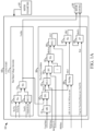
- FIG. 1A schematically illustrates a non-limiting example implementation of the flying start program instructions 168 in the controller memory 164 of FIG. 1 . including a maximum output voltage calculation component 171 and a flux current calculation component 180.
- the controller 160 is configured to execute the instructions of the maximum output voltage calculation component 171 to calculate (e.g., compute or otherwise determine) a maximum output voltage VoutMax of the inverter 150, for example, representing the maximum voltage that the drive 100 can output.
- the controller 160 is configured to execute the instructions of the flux current calculation component 180 to calculate (e.g., compute or otherwise determine) a d-axis current reference IdRefFilt based on the calculated maximum output voltage VoutMax.
- the calculated d-axis current reference IdRefFilt and the calculated maximum output voltage VoutMax are provided to the motor control component 166 which is also executed by the processor 162 of the controller 160.
- the controller 160 executes instructions of the flying start component 168 in one example to perform a flying start operation including a field weakening control operation based on the calculated d-axis current reference IdRefFilt.
- the execution or implementation of the components 171 and 180 in one example is based at least partially on one or more of the motor parameters 169 stored in the controller memory 164.
- the maximum output voltage calculation component 171 in one example includes a maximum component 172 that determines a maximum one of a maximum voltage parameter value Max Vltg. for example, corresponding to a maximum voltage that the inverter 150 can output, and a maximum motor nameplate voltage value MtrNpVltg, for example, corresponding to a nameplate voltage of the motor 104, which values are stored as motor parameters 169 in the controller memory 164.
- the maximum output voltage calculation component 171 in this example also includes a minimum component 174 that outputs the calculated maximum output voltage VoutMax as the lesser of the value output by the maximum component 172 and the output from a multiplier component 176.
- the multiplier component 176 multiplies a filtered DC bus voltage value VbusFilt, corresponding to the DC bus voltage Vdc across the DC bus capacitor C4 in the DC link circuit 140, by a utilization factor value UtilizationFactor to provide the second input to the minimum component 174.
- the bus utilization factor in one example is approximately 0.95, although other values can be used.
- the minimum component 174 calculates the maximum output voltage VoutMax as the lesser of the values from the maximum component 172 and the multiplier component 176.
- the flux current calculation component 180 calculates (e.g., computes or otherwise determines) the d-axis current reference IdRefFilt based on the calculated maximum output voltage VoutMax from the maximum output voltage calculation component 171 and based on other motor or drive parameters 169.
- the field weakening motor control during flying start operations is controlled at least partially based on the flux current calculated by the flux current calculation component 180, for example, such that if the motor speed is too high (e.g., higher than rated speed), the controller 160 will reduce the flux current during field weakening operation.
- the flux current calculation component 180 calculates includes an absolute value (ABS) component 181 that outputs the absolute value of a motor speed value OmegaOutput (e.g., corresponding to the measured speed of the motor 104).
- a divider component 182 divides the calculated maximum output voltage VoutMax by the absolute value of the motor speed to calculate a d-axis flux value FluxD.
- a multiplier component 183 multiplies the calculated d-axis flux value FluxD by a motor nameplate speed value MtrNpOmega (e.g., stored in the motor or drive parameters 169).
- the product of these values is provided as an input to a divider component 184 and is divided by a peak line to neutral motor nameplate voltage value MtrNpVltgLnPk (e.g., stored in the motor or drive parameters 169).
- the result is provided to a minimum component 185, which outputs the lesser of the output of the divider component 184 and the value 1 as a d-axis reference current scalar IdRcfScalar.
- a multiplier component 186 multiplies a rated d-axis reference current value IdRefRated (e.g., a rated flux current value stored in the motor or drive parameters 169) by the d-axis reference current scalar IdRefScalar to calculate a first d-axis current reference IdRef1 based on the calculated maximum output voltage VoutMax and the rated d-axis current reference IdRefRated.
- a rated d-axis reference current value IdRefRated e.g., a rated flux current value stored in the motor or drive parameters 169
- the first d-axis current reference IdRef1 in this example is calculated based on the motor nameplate data (e.g., nameplate speed, voltage) and rated flux current stored in the motor or drive parameters 169 of the controller memory 164 to provide an approximation of the flux current of the motor during field weakening control for flying start operation.
- the controller 160 uses the first d-axis current reference IdRcf1 for controlling the motor 104 during field weakening operation in response to the measured motor speed (e.g., motor speed value OmegaOutput) exceeding the threshold 170 at startup.
- the flux current calculation component 180 in one example also includes a minimum component 187 that outputs the minimum or lower of the first d-axis current reference IdRef1 and a second d-axis current reference IdRef2 from a flux map component 188.
- the flux map 188 in one example is a parametric equation with parameters stored in the controller memory 164 to define a relationship between per unit current and d-axis flux in the motor 104.
- the controller 1 60 evaluates the parametric equation based on the calculated d-axis flux FluxD from the divider component 182 to calculate the second d-axis current reference IdRef2 based on the calculated d-axis flux FluxD and the flux map 188 equation.
- the flux map 188 is implemented as a lookup table with entries stored in the controller memory 164.
- FIG. 1B shows one example flux map 188 with a curve 190 that is modeled and stored in the controller memory 164 as parameters of a parametric equation that can be solved by the processor 162 for d-axis current as a function of the calculated d-axis flux FluxD. or as a lookup table with entries and values (e.g., values Ld20, 30, 40, 50, 60, 190 From auto tune as shown in FIG. 1A , and indicated by circles on the curve 190 of FIG. 1B ) that are stored in the memory 164.
- the flux map 188 helps the processor 162 to determine the second d-axis current reference IdRef2 based on the calculated d-axis flux FluxD, for example, using interpolation or other suitable computational technique or approach.
- the controller 160 uses the second d-axis current reference IdRef2 to control the motor 104 during field weakening operation in response to the measured motor speed (e.g., motor speed value OmegaOutput) exceeding the threshold 170 at startup.
- the flux current calculation component 180 also includes a minimum component 187 that computes a d-axis reference current IdRef as the minimum or smaller one of the respective first and second d-axis current references IdRef1 and IdRef2.
- the controller 160 uses the d-axis reference current IdRef to control the motor 104 during field weakening operation in response to the measured motor speed exceeding the threshold 170 at startup.
- the flux current calculation component 180 also includes a low pass filter component 189 that filters the calculated d-axis current reference IdRef to compute a filtered d-axis current reference IdRefFilt.
- the controller 160 in one example uses the filtered d-axis current reference IdRefFilt to control the motor 104 during field weakening operation in response to the measured motor speed exceeding the threshold 170 at startup.
- the flux current calculation component 180 includes the low pass filter component 189 that filters one of the respective first and second d-axis current references IdRef1 and IdRef2 to compute the filtered d-axis current reference IdRefFilt, and the controller 160 in one example performs the field weakening control operation based on the computed filtered d-axis current reference IdRefFilt to control the motor 104 during field weakening operation in response to the measured motor speed exceeding the threshold 170 at startup.
- the low pass filter 189 in one example has a reset input that receives an input signal Reset to selectively enable the filter 189 in response to a Flying Start Transit from Measurement to MatchVHz state from the motor control component 166 or from a startup procedure implemented by the controller 160.
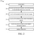
- FIG. 2 shows a method 200 implemented by the controller 160 for flying start of the motor 104. for example, by the processor 162 executing the flying start program instructions 168 stored in the memory 164.
- the motor drive power conversion system 100 is started at 202, for example, by a user or by a system component (e.g., a thermostat determining that fan cooling is needed, etc.), or an automatic restart following system power interruption, etc.
- a system component e.g., a thermostat determining that fan cooling is needed, etc.
- the controller 160 In response to startup of the system 100 at 204 in FIG. 2 , the controller 160 measures the motor shaft position and motor speed of the motor 104 and if the measured rotor speed is low, the rated flux current will be applied due to the input of the value 1 to the Min block 185 in FIG. 1A .
- the controller 160 performs a flying start operation at 208, 210 and 212 using field weakening control to control the motor 104.
- the controller 160 calculates the maximum output voltage VoutMax of the inverter 150, for example, by implementing the maximum output voltage calculation component 171 as described above in connection with FIG. 1A .
- the controller 160 calculates the d-axis current reference (e.g., IdRcf, IdRefFilt, IdRefl, IdRef2) based on the calculated maximum output voltage VoutMax, for example, by implementing the flux current calculation component 180 of FIG. 1A as described above.
- the controller 160 performs the voltage frequency (e.g., VHz) matching control operation based on the calculated d-axis current reference. Thereafter, the controller 160 transfers to normal operation at 216, for example, generating the inverter switching control signals 154 to implement speed or torque control as commanded.
- VHz voltage frequency
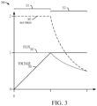
- FIG. 3 shows a graph 300 illustrating normal and field weakening control of the motor 104.
- a curve 301 showing the motor voltage
- a curve 302 showing the motor flux (e.g., stator flux ⁇ s)
- a curve 303 showing the maximum torque (e.g., T) of the motor 104 in a first speed range 311 below and at the field weakening point FWP (e.g., the threshold 170 at the rated speed in one implementation), and a second range 312 for motor speeds that exceed the threshold field weakening point FWP.
- the controller 160 operates in normal operation (e.g., 216 in FIG.
- the controller 160 can control the motor 104 with 100% per unit flux to achieve torque control proportional to the motor current, and operation and reduced flux levels would require increased current.
- the controller 160 reduces the flux to match volts hertz for a motor rotating above the field weakening point FWP for flying start operation.
- the field weaking control in the second range 312 allows the voltage (curve 301) to be maintained (e.g., according to the calculated maximum output voltage VoutMax from the maximum output voltage calculation component 171) without exceeding insulation ratings, and the controller 160 advantageously reduces the flux (curve 302) to match the high motor speed (e.g. at 212 in FIG. 2 ) using the calculated d-axis reference current (e.g., TdRefFilt), with a corresponding reduction in the maximum torque (curve 303). As shown in FIG.
- the controller 160 reduces the flux 302 by an amount that increases as the measured motor speed (e.g., OmegaOutput in FIG. 1A ) further exceeds the field weakening point FWP, for example by a factor of 1/n where n is the per unit motor speed.
- the controller 160 implements approximately constant torque control in the first (e.g., normal) range 311 and implements approximately constant power in the second range 312 up to a maximum speed, for example, limited by pull-out torque (e.g., for an induction motor 104).
- the described examples advantageously mitigate or avoid violations of the maximum output voltage rating of the power conversion system 100 and limitations of the insulation of the motor 104.
- FIGS. 4 and 5 show respective graphs 400 and 500 that illustrate certain benefits of the controller performance for high speed flying start operation of the system 100.
- the graph 400 in FIG. 4 shows a motor current curve 401 for an unsuccessful attempted flying start for a synchronous reluctance or induction motor rotating at a speed above the field weakening point FWP when a drive is started.
- the motor speed is measured during a measurement period 411 starting at time T1 in FIG. 4 .
- the drive transitions to a conventional volts hertz matching period 412, in which no field weakening control is used (e.g., the method 200 of FIG. 2 is not implemented).
- the d-axis current is not limited, and the current exceeds a trip threshold TH at time T3, causing the drive to shut down and the attempted flying start fails.
- the graph 500 in FIG. 5 shows a motor current curve 501 for a synchronous reluctance or induction motor 104 rotating at a speed above the field weakening point FWP when the drive 100 is started (at 202 in FIG. 2 ).
- the controller 160 measures the motor speed and position (e.g., at 204 in FIG. 2 ) during a measurement period 511.
- the motor speed exceeds the field weakening point FWP, such as a 50 Hz rated motor with a flying motor speed of 60 Hz.
- the controller 160 calculates the maximum output voltage VoutMax of the inverter 150, for example, by implementing the maximum output voltage calculation component 171 as described above, and the controller 160 calculates the d-axis current reference (e.g., IdRefFilt) at 210 based on the calculated maximum output voltage VoutMax, for example, by implementing the flux current calculation component 180 as described above.
- the controller 160 performs the voltage frequency matching control at 212 in FIG. 2 based on the calculated d-axis current reference IdRefFilt in a volts hertz matching period 512.
- the flux control in the matching period 512 limits the motor current (curve 501) to prevent excursion above the trip threshold TH, and the controller 160 transfers to normal operation at time T3 and thereafter (e.g.. 216 in FIG. 2 ). Normal operation then continues with the controller 160 generating the inverter switching control signals 154 to implement a desired motor control strategy.
Landscapes
- Engineering & Computer Science (AREA)
- Power Engineering (AREA)
- Control Of Ac Motors In General (AREA)
Abstract
Description
- The subject matter disclosed herein relates to power converters.
- In one aspect, a power conversion system includes an inverter configured to convert DC power to AC power to drive a motor, and a controller, configured to operate the inverter to perform a flying start operation using field weakening control responsive to a motor speed of the motor exceeding a non-zero threshold at startup of the power conversion system.
- In another aspect, a method includes measuring a motor speed of a motor, responsive to startup of a power conversion system, and performing a flying start operation using field weakening control to control the motor responsive to the motor speed exceeding a non-zero threshold at startup of the power conversion system.
- In a further aspect, a non-transitory computer readable medium has computer executable instructions which, when executed by a processor, cause the processor to measure a motor speed of a motor, responsive to startup of a power conversion system, and perform a flying start operation using field weakening control to control the motor responsive to the motor speed exceeding a non-zero threshold at startup of the power conversion system.
-
-
FIG. 1 is a schematic diagram of a motor drive power conversion system. -
FIG. 1A is a schematic diagram of a flying start component. -
FIG. 1B is a graph of a flux map. -
FIG. 1C shows three flying start states. -
FIG. 2 is a flow diagram of a method. -
FIG. 3 is a graph. -
FIG. 4 is a graph. -
FIG. 5 is a graph. - Referring now to the figures, several embodiments or implementations are hereinafter described in conjunction with the drawings, wherein like reference numerals are used to refer to like elements throughout, and various features are not necessarily drawn to scale. Flying start operation of a motor is difficult in some circumstances, such as for induction motors (IMs) or synchronous reluctance motors (SynRM) that may be rotating at or above a rated speed. Attempting volts Hz matching at these motor speeds without field weakening control can cause excess current draw and/or high voltage spikes and lead to overcurrent or overvoltage trips in a motor drive. Described examples provide solutions as methods, power conversion systems, and computer readable mediums for implementing flying start of a rotating motor by field weakening control to control the motor in response to the motor speed exceeding the rated speed or other non-zero threshold at startup of the power conversion system. Example implementations mitigate or avoid unwanted overvoltage or overcurrent trips without adding components or cost to motor drive power conversion systems to provide a solution that can help enable reliable flying start operation for motors spinning at high speeds upon startup of the motor drive.
- Flying start capabilities can be useful in a variety of applications, such as motor drives configured to drive outdoor fans or pumps in wells. In these applications, the blades of a driven fan or pump may rotate when the drive is turned off, due to ambient wind near an outdoor fan or flow of a pumped fluid in a well. Starting a drive when the rotor of the driven motor is rotating is referred to as a flying start and may result in high current spikes in the drive. Prior to actively driving the motor, the rotor shaft speed and position (e.g., angle) can be measured, and volts hertz matching is performed to match the drive output voltage and speed to the respective CEMF and rotor rotation to mitigate or avoid high current spikes when active driving of the rotating motor begins.
- Referring initially to
FIGS. 1-1C .FIG. 1 shows an example electrical system with a motor drivepower conversion system 100 that converts electrical power from anexternal power source 102 to drive amotor load 104.FIG. 1C shows threeflying start states power conversion system 100 in one example, including afirst state 191 for measurement including obtaining motor shaft position and speed, asecond state 192 for matching volts and hertz to match the drive output voltage and frequency with motor CEMF and speed, and athird state 193 for normal operation with open loop control. In one example, themotor 104 is an induction motor. In another example, themotor 104 is a synchronous reluctance motor. In one example, the motor drivepower conversion system 100 is part of a fan system, where themotor 104 drives a fan, such as for environmental control of a building (e.g., heating and/or air conditioning). In another example the motor drivepower conversion system 100 is part of a pump system, in which themotor 104 drives a pump that pumps a fluid in an industrial facility or at a well or mine. - The
system 100 in one example implements intelligent flying starts by field weakening control in responsive to the motor speed exceeding a non-zero threshold at startup of thepower conversion system 100, and the system ramps the drive output voltage and frequency to match the CEMF of the rotating motor and eventually resumes or starts normal operation without causing current spikes or tripping the drive. The example flying start apparatus and techniques can be used to start a rotating motor and resume normal operation as quick as possible, with a minimal impact on load or speed for a variety of applications such as fan/pump systems. - The motor drive
power conversion system 100 receives single or multiphase AC input power from theexternal power source 102. The illustrated example receives a three-phase input. In other examples, single phase or other multiphase embodiments are possible. Themotor drive 100 converts input power from thesource 102 to deliver output power to drive themotor load 104. Themotor drive 100 includes a three-phaseinput filter circuit 120, such as an LC or LCL, filter. Themotor drive 100 also includes arectifier 130, a DC bus orDC link circuit 140, and anoutput inverter 150. - The
rectifier 130 and theinverter 150 are operated by acontroller 160. Thecontroller 160 includes aprocessor 162, anelectronic memory 164 or other non-transitory computer readable medium that stores data and program instructions, as well as arectifier controller 132 and aninverter controller 152. Theprocessor 162 in one example includes an internal electronic memory (not shown) that stores data values and provides a non-transitory computer-readable medium that stores computer-executable instructions which, when executed by theprocessor 162, cause theprocessor 162 to implement the various functions and features described herein. In another example, thememory 164 is external to theprocessor 162 and thememory 164 stores data values and provides a non-transitory computer-readable medium that stores computer-executable instructions which, when executed by theprocessor 162, cause theprocessor 162 to implement the various functions and features described herein. Thecontroller 160 and the components thereof may be implemented as any suitable hardware, processor-executed software, processor-executed firmware, logic, and/or combinations thereof wherein the illustratedcontroller 160 can be implemented in processor-executed software or firmware providing various control functions by which thecontroller 160 receives feedback and/or input signals and/or values (e.g., sctpoint(s)) and provides rectifier and inverterswitching control signals rectifier 130 and switches S7-S12 of theinverter 150 to convert input power for providing AC output power to drive themotor 104. In addition, thecontroller 160 and thecomponents - The
motor drive 100 in one example provides an active front end (AFE) including a switching rectifier (also referred to as a converter) 130 receiving three-phase power from thesource 102 through thefilter circuit 120. Theactive rectifier 130 includes rectifier switches S1-S6, which may be insulated gate bipolar transistors (IGBTs) or other suitable form of semiconductor-based switching devices operable according to a corresponding rectifierswitching control signal 134 to selectively conduct current when actuated. In addition, diodes are connected across the individual IGBTs S1-S6. In operation, switching of the rectifier switches S1-S6 is controlled according to pulse width modulated rectifierswitching control signals 134 from therectifier switching controller 132 to provide active rectification of the AC input power from thesource 102 to provide a DC bus voltage Vdc across a DC bus capacitor C4 in theDC link circuit 140. - The
inverter 150 includes switches S7-S12 coupled to receive power from theDC bus 140 and to provide AC output power to themotor 104. The inverter switches S7-S12 can be any form of suitable high-speed switching devices, including without limitation IGBTs that operate according to switchingcontrol signals 154 from the inverterswitching control component 152 of thedrive controller 160. The individual inverter switching devices S7-S12 selectively couple a respective AC node of the inverter output with a respective one of first and second DC nodes of theDC bus circuit 140 according to a respective inverterswitching control signal 154. In certain examples, thecontroller 160 receives various input signals or values, including setpoint signals or values for desired output operation, such as motor speed, position, torque, etc., as well as feedback signals or values representing operational values of various portions of themotor drive 100 and electrical system components of thedrive 100. In addition, thecontroller 160 in certain examples receives one or more voltage and/or current feedback signals or values from sensors to indicate the DC bus voltage Vdc, line to line AC input voltage values, motor line to line voltage values and/or currents, etc. - The
memory 164 stores motorcontrol program instructions 166, such as speed control, torque control, etc., for normal operation, as well as flyingstart program instructions 168 andmotor parameters 169 that include anon-zero threshold 170, for example, the rated speed of themotor 104. Themotor parameters 169 includes stored parameters associated with operation of themotor drive 100, such as drive configuration parameters. Thecontroller 160 is configured by theexecutable instructions inverter 150 to perform a flying start operation using field weakening control in response to a motor speed of themotor 104 exceeding thenon-zero threshold 170 at startup of thepower conversion system 100. -
FIG. 1A schematically illustrates a non-limiting example implementation of the flyingstart program instructions 168 in thecontroller memory 164 ofFIG. 1 . including a maximum outputvoltage calculation component 171 and a fluxcurrent calculation component 180. Thecontroller 160 is configured to execute the instructions of the maximum outputvoltage calculation component 171 to calculate (e.g., compute or otherwise determine) a maximum output voltage VoutMax of theinverter 150, for example, representing the maximum voltage that thedrive 100 can output. Thecontroller 160 is configured to execute the instructions of the fluxcurrent calculation component 180 to calculate (e.g., compute or otherwise determine) a d-axis current reference IdRefFilt based on the calculated maximum output voltage VoutMax. In one implementation, the calculated d-axis current reference IdRefFilt and the calculated maximum output voltage VoutMax are provided to themotor control component 166 which is also executed by theprocessor 162 of thecontroller 160. Thecontroller 160 executes instructions of the flyingstart component 168 in one example to perform a flying start operation including a field weakening control operation based on the calculated d-axis current reference IdRefFilt. - The execution or implementation of the
components motor parameters 169 stored in thecontroller memory 164. The maximum outputvoltage calculation component 171 in one example includes amaximum component 172 that determines a maximum one of a maximum voltage parameter value Max Vltg. for example, corresponding to a maximum voltage that theinverter 150 can output, and a maximum motor nameplate voltage value MtrNpVltg, for example, corresponding to a nameplate voltage of themotor 104, which values are stored asmotor parameters 169 in thecontroller memory 164. - The maximum output
voltage calculation component 171 in this example also includes aminimum component 174 that outputs the calculated maximum output voltage VoutMax as the lesser of the value output by themaximum component 172 and the output from amultiplier component 176. Themultiplier component 176 multiplies a filtered DC bus voltage value VbusFilt, corresponding to the DC bus voltage Vdc across the DC bus capacitor C4 in theDC link circuit 140, by a utilization factor value UtilizationFactor to provide the second input to theminimum component 174. The bus utilization factor in one example is approximately 0.95, although other values can be used. Theminimum component 174 calculates the maximum output voltage VoutMax as the lesser of the values from themaximum component 172 and themultiplier component 176. - The flux
current calculation component 180 calculates (e.g., computes or otherwise determines) the d-axis current reference IdRefFilt based on the calculated maximum output voltage VoutMax from the maximum outputvoltage calculation component 171 and based on other motor or driveparameters 169. The field weakening motor control during flying start operations is controlled at least partially based on the flux current calculated by the fluxcurrent calculation component 180, for example, such that if the motor speed is too high (e.g., higher than rated speed), thecontroller 160 will reduce the flux current during field weakening operation. The fluxcurrent calculation component 180 calculates includes an absolute value (ABS)component 181 that outputs the absolute value of a motor speed value OmegaOutput (e.g., corresponding to the measured speed of the motor 104). Adivider component 182 divides the calculated maximum output voltage VoutMax by the absolute value of the motor speed to calculate a d-axis flux value FluxD. - A
multiplier component 183 multiplies the calculated d-axis flux value FluxD by a motor nameplate speed value MtrNpOmega (e.g., stored in the motor or drive parameters 169). The product of these values is provided as an input to adivider component 184 and is divided by a peak line to neutral motor nameplate voltage value MtrNpVltgLnPk (e.g., stored in the motor or drive parameters 169). The result is provided to aminimum component 185, which outputs the lesser of the output of thedivider component 184 and thevalue 1 as a d-axis reference current scalar IdRcfScalar. Amultiplier component 186 multiplies a rated d-axis reference current value IdRefRated (e.g., a rated flux current value stored in the motor or drive parameters 169) by the d-axis reference current scalar IdRefScalar to calculate a first d-axis current reference IdRef1 based on the calculated maximum output voltage VoutMax and the rated d-axis current reference IdRefRated. The first d-axis current reference IdRef1 in this example is calculated based on the motor nameplate data (e.g., nameplate speed, voltage) and rated flux current stored in the motor or driveparameters 169 of thecontroller memory 164 to provide an approximation of the flux current of the motor during field weakening control for flying start operation. In one example, thecontroller 160 uses the first d-axis current reference IdRcf1 for controlling themotor 104 during field weakening operation in response to the measured motor speed (e.g., motor speed value OmegaOutput) exceeding thethreshold 170 at startup. - The flux
current calculation component 180 in one example also includes aminimum component 187 that outputs the minimum or lower of the first d-axis current reference IdRef1 and a second d-axis current reference IdRef2 from aflux map component 188. Theflux map 188 in one example is a parametric equation with parameters stored in thecontroller memory 164 to define a relationship between per unit current and d-axis flux in themotor 104. In this example, thecontroller 1 60 evaluates the parametric equation based on the calculated d-axis flux FluxD from thedivider component 182 to calculate the second d-axis current reference IdRef2 based on the calculated d-axis flux FluxD and theflux map 188 equation. - In another implementation, the
flux map 188 is implemented as a lookup table with entries stored in thecontroller memory 164.FIG. 1B shows oneexample flux map 188 with acurve 190 that is modeled and stored in thecontroller memory 164 as parameters of a parametric equation that can be solved by theprocessor 162 for d-axis current as a function of the calculated d-axis flux FluxD. or as a lookup table with entries and values (e.g., values Ld20, 30, 40, 50, 60, 190 From auto tune as shown inFIG. 1A , and indicated by circles on thecurve 190 ofFIG. 1B ) that are stored in thememory 164. As a lookup table, theflux map 188 helps theprocessor 162 to determine the second d-axis current reference IdRef2 based on the calculated d-axis flux FluxD, for example, using interpolation or other suitable computational technique or approach. In one implementation, thecontroller 160 uses the second d-axis current reference IdRef2 to control themotor 104 during field weakening operation in response to the measured motor speed (e.g., motor speed value OmegaOutput) exceeding thethreshold 170 at startup. - In the illustrated example, the flux
current calculation component 180 also includes aminimum component 187 that computes a d-axis reference current IdRef as the minimum or smaller one of the respective first and second d-axis current references IdRef1 and IdRef2. In one implementation, thecontroller 160 uses the d-axis reference current IdRef to control themotor 104 during field weakening operation in response to the measured motor speed exceeding thethreshold 170 at startup. - In the illustrated example, the flux
current calculation component 180 also includes a lowpass filter component 189 that filters the calculated d-axis current reference IdRef to compute a filtered d-axis current reference IdRefFilt. Thecontroller 160 in one example uses the filtered d-axis current reference IdRefFilt to control themotor 104 during field weakening operation in response to the measured motor speed exceeding thethreshold 170 at startup. In another example, the fluxcurrent calculation component 180 includes the lowpass filter component 189 that filters one of the respective first and second d-axis current references IdRef1 and IdRef2 to compute the filtered d-axis current reference IdRefFilt, and thecontroller 160 in one example performs the field weakening control operation based on the computed filtered d-axis current reference IdRefFilt to control themotor 104 during field weakening operation in response to the measured motor speed exceeding thethreshold 170 at startup. Thelow pass filter 189 in one example has a reset input that receives an input signal Reset to selectively enable thefilter 189 in response to a Flying Start Transit from Measurement to MatchVHz state from themotor control component 166 or from a startup procedure implemented by thecontroller 160. - Referring also to
FIGS. 2-5 ,FIG. 2 shows amethod 200 implemented by thecontroller 160 for flying start of themotor 104. for example, by theprocessor 162 executing the flyingstart program instructions 168 stored in thememory 164. The motor drivepower conversion system 100 is started at 202, for example, by a user or by a system component (e.g., a thermostat determining that fan cooling is needed, etc.), or an automatic restart following system power interruption, etc. - In response to startup of the
system 100 at 204 inFIG. 2 , thecontroller 160 measures the motor shaft position and motor speed of themotor 104 and if the measured rotor speed is low, the rated flux current will be applied due to the input of thevalue 1 to the Min block 185 inFIG. 1A . - The
controller 160 performs a flying start operation at 208, 210 and 212 using field weakening control to control themotor 104. At 208, thecontroller 160 calculates the maximum output voltage VoutMax of theinverter 150, for example, by implementing the maximum outputvoltage calculation component 171 as described above in connection withFIG. 1A . At 210, thecontroller 160 calculates the d-axis current reference (e.g., IdRcf, IdRefFilt, IdRefl, IdRef2) based on the calculated maximum output voltage VoutMax, for example, by implementing the fluxcurrent calculation component 180 ofFIG. 1A as described above. At 212, thecontroller 160 performs the voltage frequency (e.g., VHz) matching control operation based on the calculated d-axis current reference. Thereafter, thecontroller 160 transfers to normal operation at 216, for example, generating the inverterswitching control signals 154 to implement speed or torque control as commanded. -
FIG. 3 shows agraph 300 illustrating normal and field weakening control of themotor 104. including acurve 301 showing the motor voltage, acurve 302 showing the motor flux (e.g., stator flux ψs), and acurve 303 showing the maximum torque (e.g., T) of themotor 104 in afirst speed range 311 below and at the field weakening point FWP (e.g., thethreshold 170 at the rated speed in one implementation), and asecond range 312 for motor speeds that exceed the threshold field weakening point FWP. In thefirst range 311 in one example, thecontroller 160 operates in normal operation (e.g., 216 inFIG. 2 ) with motor flux (e.g., curve 302) approximately constant (e.g., at or near 100%, labeled "1" in per unit scaling of the graph 300 (the max torque (curve 303) can be kept at constant due to fixed max current limit), and the voltage (curve 301) approximately proportional to the motor speed, where T=ψs×is. In thefirst range 311. thecontroller 160 can control themotor 104 with 100% per unit flux to achieve torque control proportional to the motor current, and operation and reduced flux levels would require increased current. - In the
second range 312 for an induction orsynchronous reluctance motor 104, thecontroller 160 reduces the flux to match volts hertz for a motor rotating above the field weakening point FWP for flying start operation. The field weaking control in thesecond range 312 allows the voltage (curve 301) to be maintained (e.g., according to the calculated maximum output voltage VoutMax from the maximum output voltage calculation component 171) without exceeding insulation ratings, and thecontroller 160 advantageously reduces the flux (curve 302) to match the high motor speed (e.g.. at 212 inFIG. 2 ) using the calculated d-axis reference current (e.g., TdRefFilt), with a corresponding reduction in the maximum torque (curve 303). As shown inFIG. 3 , thecontroller 160 reduces theflux 302 by an amount that increases as the measured motor speed (e.g., OmegaOutput inFIG. 1A ) further exceeds the field weakening point FWP, for example by a factor of 1/n where n is the per unit motor speed. In one example, thecontroller 160 implements approximately constant torque control in the first (e.g., normal)range 311 and implements approximately constant power in thesecond range 312 up to a maximum speed, for example, limited by pull-out torque (e.g., for an induction motor 104). The described examples advantageously mitigate or avoid violations of the maximum output voltage rating of thepower conversion system 100 and limitations of the insulation of themotor 104. -
FIGS. 4 and 5 showrespective graphs system 100. Thegraph 400 inFIG. 4 shows a motorcurrent curve 401 for an unsuccessful attempted flying start for a synchronous reluctance or induction motor rotating at a speed above the field weakening point FWP when a drive is started. In this example, the motor speed is measured during ameasurement period 411 starting at time T1 inFIG. 4 . At time T2, the drive transitions to a conventional voltshertz matching period 412, in which no field weakening control is used (e.g., themethod 200 ofFIG. 2 is not implemented). In this case, the d-axis current is not limited, and the current exceeds a trip threshold TH at time T3, causing the drive to shut down and the attempted flying start fails. - The
graph 500 inFIG. 5 shows a motorcurrent curve 501 for a synchronous reluctance orinduction motor 104 rotating at a speed above the field weakening point FWP when thedrive 100 is started (at 202 inFIG. 2 ). At time T1 inFIG. 5 , thecontroller 160 measures the motor speed and position (e.g., at 204 inFIG. 2 ) during ameasurement period 511. In this example, the motor speed exceeds the field weakening point FWP, such as a 50 Hz rated motor with a flying motor speed of 60 Hz. Thecontroller 160 calculates the maximum output voltage VoutMax of theinverter 150, for example, by implementing the maximum outputvoltage calculation component 171 as described above, and thecontroller 160 calculates the d-axis current reference (e.g., IdRefFilt) at 210 based on the calculated maximum output voltage VoutMax, for example, by implementing the fluxcurrent calculation component 180 as described above. At time T2 inFIG. 5 . thecontroller 160 performs the voltage frequency matching control at 212 inFIG. 2 based on the calculated d-axis current reference IdRefFilt in a volts hertz matching period 512. The flux control in the matching period 512 limits the motor current (curve 501) to prevent excursion above the trip threshold TH, and thecontroller 160 transfers to normal operation at time T3 and thereafter (e.g.. 216 inFIG. 2 ). Normal operation then continues with thecontroller 160 generating the inverterswitching control signals 154 to implement a desired motor control strategy. - Various embodiments have been described with reference to the accompanying drawings. Modifications and changes may be made thereto, and additional embodiments may be implemented, without departing from the broader scope of the invention as set forth in the claims that follow. The specification and drawings are accordingly to be regarded in an illustrative rather than restrictive sense. The above examples are merely illustrative of several possible embodiments of various aspects of the present disclosure, wherein equivalent alterations and/or modifications will occur to others skilled in the art upon reading and understanding this specification and the annexed drawings. In addition, although a particular feature of the disclosure may have been disclosed with respect to only one of several implementations, such feature may be combined with one or more other features of the other implementations as may be desired and advantageous for any given or particular application. Also, to the extent that the terms "including", "includes", "having", "has", "with", or variants thereof are used in the detailed description and/or in the claims, such terms are intended to be inclusive in a manner similar to the term "comprising".
- The following is a list of further preferred embodiments of the invention:
- Embodiment 1: A power conversion system, comprising:
- an inverter configured to convert DC power to AC power to drive a motor; and
- a controller, configured to operate the inverter to perform a flying start operation using field weakening control responsive to a motor speed of the motor exceeding a non-zero threshold at startup of the power conversion system.
- Embodiment 2: The power conversion system of
embodiment 1, wherein the non-zero threshold is equal to a rated speed of the motor. - Embodiment 3: The power conversion system of
embodiment 2, wherein the controller is configured to, responsive to the motor speed exceeding the non-zero threshold at the startup of the power conversion system:- calculate a maximum output voltage of the inverter;
- calculate a d-axis current reference based on the calculated maximum output voltage; and
- perform a flying start operation by field weakening control based on the calculated d-axis current reference.
- Embodiment 4: The power conversion system of
embodiment 3, wherein the controller is configured to, responsive to the motor speed exceeding the non-zero threshold at the startup of the power conversion system:- calculate a first d-axis current reference based on the calculated maximum output voltage and a rated d-axis current reference;
- determine a second d-axis current reference based on a calculated d-axis flux and a flux map; and
- calculate the d-axis current reference based on a smaller one of the first and second d-axis current references.
- Embodiment 5: The power conversion system of embodiment 4, wherein the controller is configured to:
- filter the calculated d-axis current reference using a low pass filter to compute a filtered d-axis current reference; and
- perform the flying start operation by field weakening control based on the computed filtered d-axis current reference.
- Embodiment 6: The power conversion system of
embodiment 1, wherein the controller is configured to, responsive to the motor speed exceeding the non-zero threshold at the startup of the power conversion system:- calculate a maximum output voltage of the inverter;
- calculate a d-axis current reference based on the calculated maximum output voltage; and
- perform a flying start operation by field weakening control based on the calculated d-axis current reference.
- Embodiment 7: The power conversion system of embodiment 6, wherein the controller is configured to, responsive to the motor speed exceeding the non-zero threshold at the startup of the power conversion system:
- calculate a first d-axis current reference based on the calculated maximum output voltage and a rated d-axis current reference;
- determine a second d-axis current reference based on a calculated d-axis flux and a flux map; and
- calculate the d-axis current reference based on a smaller one of the first and second d-axis current references.
- Embodiment 8: The power conversion system of
embodiment 7, wherein the controller is configured to:- filter the calculated d-axis current reference using a low pass filter to compute a filtered d-axis current reference; and
- perform the flying start operation by field weakening control based on the computed filtered d-axis current reference.
- Embodiment 9: The power conversion system of embodiment 6, wherein the controller is configured to:
- filter the calculated d-axis current reference using a low pass filter to compute a filtered d-axis current reference; and
- perform the flying start operation by field weakening control based on the computed filtered d-axis current reference.
- Embodiment 10: The power conversion system of
embodiment 1, wherein the motor is an induction motor or a synchronous reluctance motor. - Embodiment 11: A method, comprising:
- measuring a motor speed of a motor, responsive to startup of a power conversion system; and
- performing a flying start operation using field weakening control to control the motor responsive to the motor speed exceeding a non-zero threshold at startup of the power conversion system.
- Embodiment 12: The method of embodiment 11, wherein the non-zero threshold is equal to a rated speed of the motor.
- Embodiment 13: The method of embodiment 11, wherein performing the flying start operation comprises:
- calculating a maximum output voltage of the inverter;
- calculating a d-axis current reference based on the calculated maximum output voltage; and
- performing a field weakening control based on the calculated d-axis current reference.
- Embodiment 14: The method of embodiment 13, wherein performing the flying start operation comprises:
- calculating a first d-axis current reference based on the calculated maximum output voltage and a rated d-axis current reference;
- determining a second d-axis current reference based on a calculated d-axis flux and a flux map; and
- calculating the d-axis current reference based on a smaller one of the first and second d-axis current references.
- Embodiment 15: The method of embodiment 14, wherein performing the flying start operation comprises:
- filtering the calculated d-axis current reference using a low pass filter to compute a filtered d-axis current reference; and
- performing a field weakening control based on the computed filtered d-axis current reference.
- Embodiment 16: A non-transitory computer readable medium having computer executable instructions which, when executed by a processor, cause the processor to:
- measure a motor speed of a motor, responsive to startup of a power conversion system; and
- perform a flying start operation using field weakening control to control the motor responsive to the motor speed exceeding a non-zero threshold at startup of the power conversion system.
- Embodiment 17: The non-transitory computer readable medium of embodiment 16, wherein the non-zero threshold is equal to a rated speed of the motor.
- Embodiment 18: The non-transitory computer readable medium of embodiment 16, comprising further computer executable instructions which, when executed by a processor, cause the processor to:
- calculate a maximum output voltage of the inverter;
- calculate a d-axis current reference based on the calculated maximum output voltage; and
- perform a field weakening control based on the calculated d-axis current reference.
- Embodiment 19: The non-transitory computer readable medium of embodiment 18, comprising further computer executable instructions which, when executed by a processor, cause the processor to:
- calculate a first d-axis current reference based on the calculated maximum output voltage and a rated d-axis current reference;
- determine a second d-axis current reference based on a calculated d-axis flux and a flux map; and
- calculate the d-axis current reference based on a smaller one of the first and second d-axis current references.
- Embodiment 20: The non-transitory computer readable medium of embodiment 19, comprising further computer executable instructions which, when executed by a processor, cause the processor to:
- filter the calculated d-axis current reference using a low pass filter to compute a filtered d-axis current reference; and
- perform the field weakening control based on the computed filtered d-axis current reference.
Claims (15)
- A power conversion system, comprising:an inverter configured to convert DC power to AC power to drive a motor; anda controller, configured to operate the inverter to perform a flying start operation using field weakening control responsive to a motor speed of the motor exceeding a non-zero threshold at startup of the power conversion system.
- The power conversion system of claim 1, wherein the non-zero threshold is equal to a rated speed of the motor.
- The power conversion system of claim 2, wherein the controller is configured to, responsive to the motor speed exceeding the non-zero threshold at the startup of the power conversion system:calculate a maximum output voltage of the inverter;calculate a d-axis current reference based on the calculated maximum output voltage; andperform a flying start operation by field weakening control based on the calculated d-axis current reference.
- The power conversion system of claim 3, wherein the controller is configured to, responsive to the motor speed exceeding the non-zero threshold at the startup of the power conversion system:calculate a first d-axis current reference based on the calculated maximum output voltage and a rated d-axis current reference;determine a second d-axis current reference based on a calculated d-axis flux and a flux map; andcalculate the d-axis current reference based on a smaller one of the first and second d-axis current references.
- The power conversion system of claim 4, wherein the controller is configured to:filter the calculated d-axis current reference using a low pass filter to compute a filtered d-axis current reference; andperform the flying start operation by field weakening control based on the computed filtered d-axis current reference.
- The power conversion system of one of claims 1 to 5, wherein the controller is configured to, responsive to the motor speed exceeding the non-zero threshold at the startup of the power conversion system:calculate a maximum output voltage of the inverter;calculate a d-axis current reference based on the calculated maximum output voltage; and
perform a flying start operation by field weakening control based on the calculated d-axis current reference. - The power conversion system of claim 6, wherein the controller is configured to, responsive to the motor speed exceeding the non-zero threshold at the startup of the power conversion system:calculate a first d-axis current reference based on the calculated maximum output voltage and a rated d-axis current reference;determine a second d-axis current reference based on a calculated d-axis flux and a flux map; andcalculate the d-axis current reference based on a smaller one of the first and second d-axis current references.
- The power conversion system of claim 7, wherein the controller is configured to:filter the calculated d-axis current reference using a low pass filter to compute a filtered d-axis current reference; andperform the flying start operation by field weakening control based on the computed filtered d-axis current reference.
- The power conversion system of claim 6, wherein the controller is configured to:filter the calculated d-axis current reference using a low pass filter to compute a filtered d-axis current reference; andperform the flying start operation by field weakening control based on the computed filtered d-axis current reference.
- The power conversion system of one of claims 1 to 9, wherein the motor is an induction motor or a synchronous reluctance motor.
- A method, comprising:measuring a motor speed of a motor, responsive to startup of a power conversion system; andperforming a flying start operation using field weakening control to control the motor responsive to the motor speed exceeding a non-zero threshold at startup of the power conversion system.
- The method of claim 11, wherein the non-zero threshold is equal to a rated speed of the motor.
- The method of claim 11 or 12, wherein performing the flying start operation comprises:calculating a maximum output voltage of the inverter;
calculating a d-axis current reference based on the calculated maximum output voltage; andperforming a field weakening control based on the calculated d-axis current reference; and/orwherein performing the flying start operation comprises:calculating a first d-axis current reference based on the calculated maximum output voltage and a rated d-axis current reference;determining a second d-axis current reference based on a calculated d-axis flux and a flux map; andcalculating the d-axis current reference based on a smaller one of the first and second d-axis current references; and/orwherein performing the flying start operation comprises:filtering the calculated d-axis current reference using a low pass filter to compute a filtered d-axis current reference; andperforming a field weakening control based on the computed filtered d-axis current reference. - A non-transitory computer readable medium having computer executable instructions which, when executed by a processor, cause the processor to:measure a motor speed of a motor, responsive to startup of a power conversion system; andperform a flying start operation using field weakening control to control the motor responsive to the motor speed exceeding a non-zero threshold at startup of the power conversion system.
- The non-transitory computer readable medium of claim 14, wherein the non-zero threshold is equal to a rated speed of the motor; or
comprising further computer executable instructions which, when executed by a processor, cause the processor to:calculate a maximum output voltage of the inverter;calculate a d-axis current reference based on the calculated maximum output voltage; andperform a field weakening control based on the calculated d-axis current reference; and/orcomprising further computer executable instructions which, when executed by a processor, cause the processor to:calculate a first d-axis current reference based on the calculated maximum output voltage and a rated d-axis current reference;determine a second d-axis current reference based on a calculated d-axis flux and a flux map; andcalculate the d-axis current reference based on a smaller one of the first and second d-axis current references; and/orcomprising further computer executable instructions which, when executed by a processor, cause the processor to:filter the calculated d-axis current reference using a low pass filter to compute a filtered d-axis current reference; andperform the field weakening control based on the computed filtered d-axis current reference.
Applications Claiming Priority (1)
| Application Number | Priority Date | Filing Date | Title |
|---|---|---|---|
| US18/065,170 US12176837B2 (en) | 2022-12-13 | 2022-12-13 | Motor flying start using field weakening control |
Publications (1)
| Publication Number | Publication Date |
|---|---|
| EP4387082A1 true EP4387082A1 (en) | 2024-06-19 |
Family
ID=89119174
Family Applications (1)
| Application Number | Title | Priority Date | Filing Date |
|---|---|---|---|
| EP23214242.2A Pending EP4387082A1 (en) | 2022-12-13 | 2023-12-05 | Motor flying start using field weakening control |
Country Status (2)
| Country | Link |
|---|---|
| US (1) | US12176837B2 (en) |
| EP (1) | EP4387082A1 (en) |
Family Cites Families (9)
| Publication number | Priority date | Publication date | Assignee | Title |
|---|---|---|---|---|
| US8324851B2 (en) | 2009-03-04 | 2012-12-04 | Rockwell Automation Technologies, Inc. | Method for determining a rotor position in a permanent magnet motor |
| DE102013221767A1 (en) | 2013-10-25 | 2015-04-30 | Robert Bosch Gmbh | Method, apparatus and system for operating a rotating electrical machine |
| US9369073B1 (en) | 2015-03-20 | 2016-06-14 | Linestream Technologies | Load-adaptive smooth startup method for sensorless field-oriented control of permanent magnet synchronous motors |
| KR101776240B1 (en) | 2015-08-31 | 2017-09-07 | 엘지전자 주식회사 | Motor driving apparatus and home appliance including the same |
| US9985565B2 (en) * | 2016-04-18 | 2018-05-29 | Rockwell Automation Technologies, Inc. | Sensorless motor drive vector control with feedback compensation for filter capacitor current |
| US9762155B1 (en) | 2016-05-24 | 2017-09-12 | Texas Instruments Incorporated | Rotor flux angle and torque trajectory control apparatus and methods |
| EP3751723A1 (en) | 2019-06-10 | 2020-12-16 | Black & Decker Inc. | Field-oriented sensorless brushless motor control in a power tool |
| CN111327234B (en) | 2020-02-28 | 2021-07-23 | 北京航空航天大学 | Position sensorless control method of permanent magnet fault-tolerant motor system at low speed |
| US11502636B1 (en) | 2021-07-09 | 2022-11-15 | Rockwell Automation Technologies, Inc. | IPM motor flying start using high frequency injection |
-
2022
- 2022-12-13 US US18/065,170 patent/US12176837B2/en active Active
-
2023
- 2023-12-05 EP EP23214242.2A patent/EP4387082A1/en active Pending
Non-Patent Citations (3)
| Title |
|---|
| "Electric Motor Control", 1 January 2017, ELSEVIER, ISBN: 978-0-12-812138-2, article SANG-HOON KIM: "High-speed operation of alternating current motors", pages: 341 - 371, XP093154431, DOI: 10.1016/B978-0-12-812138-2.00008-8 * |
| RADOSLAW NALEPA ET AL: "Optimum Trajectory Control of the Current Vector of a Nonsalient-Pole PMSM in the Field-Weakening Region", IEEE TRANSACTIONS ON INDUSTRIAL ELECTRONICS, IEEE SERVICE CENTER, PISCATAWAY, NJ, USA, vol. 59, no. 7, 1 July 2012 (2012-07-01), pages 2867 - 2876, XP011417616, ISSN: 0278-0046, DOI: 10.1109/TIE.2011.2116755 * |
| SHUN TANIGUCHI ET AL: "A Restart Control Method for Position Sensorless PMSM Drive Systems Without Potential Transformer for Railway Vehicle Traction", ELECTRICAL ENGINEERING IN JAPAN, JOHN WILEY & SONS, INC, US, vol. 193, no. 3, 20 July 2015 (2015-07-20), pages 44 - 53, XP071651452, ISSN: 0424-7760, DOI: 10.1002/EEJ.22756 * |
Also Published As
| Publication number | Publication date |
|---|---|
| US20240195339A1 (en) | 2024-06-13 |
| US12176837B2 (en) | 2024-12-24 |
Similar Documents
| Publication | Publication Date | Title |
|---|---|---|
| EP2838193B1 (en) | Method and apparatus for stability control of open loop motor drive operation | |
| US9374028B2 (en) | Transition scheme for position sensorless control of AC motor drives | |
| US9054611B2 (en) | Method and apparatus for stability control of open loop motor drive operation | |
| CN104488184A (en) | Motor drive control device | |
| JP6463966B2 (en) | Motor driving device, motor driving module and refrigeration equipment | |
| US9985565B2 (en) | Sensorless motor drive vector control with feedback compensation for filter capacitor current | |
| JP2002247876A (en) | Inverter device, compressor control device, refrigeration / air conditioning device control device, motor control method, compressor, refrigeration / air conditioning device | |
| JPWO2016167041A1 (en) | Motor drive device | |
| CN103368477A (en) | A driving device of a synchronous motor and a blowing device using the same | |
| US11626821B2 (en) | Sensorless control of a motor by variable frequency signal injection | |
| US12176837B2 (en) | Motor flying start using field weakening control | |
| EP4117169A1 (en) | Ipm motor flying start using high frequency injection | |
| JP3985792B2 (en) | Electric motor drive device and air conditioner using the same | |
| JP5902781B1 (en) | Permanent magnet synchronous motor drive device | |
| JPH11136994A (en) | Three-phase induction motor drive | |
| JP7566174B2 (en) | Power conversion devices, motor drive devices and refrigeration cycle application devices | |
| JP6462821B2 (en) | Motor drive device | |
| JP2018042315A (en) | Inverter controller | |
| WO2016035434A1 (en) | Motor drive device | |
| JP2014187802A (en) | Motor drive device | |
| GB2538493A (en) | A control method and system | |
| JP5056106B2 (en) | Inverter control device for motor drive and equipment using the device | |
| EP3872982B1 (en) | Control unit and control method for controlling a motor | |
| CN112219350A (en) | Motor drive and air conditioner | |
| CN110612662A (en) | Control systems for rotating electric machines |
Legal Events
| Date | Code | Title | Description |
|---|---|---|---|
| PUAI | Public reference made under article 153(3) epc to a published international application that has entered the european phase |
Free format text: ORIGINAL CODE: 0009012 |
|
| STAA | Information on the status of an ep patent application or granted ep patent |
Free format text: STATUS: THE APPLICATION HAS BEEN PUBLISHED |
|
| AK | Designated contracting states |
Kind code of ref document: A1 Designated state(s): AL AT BE BG CH CY CZ DE DK EE ES FI FR GB GR HR HU IE IS IT LI LT LU LV MC ME MK MT NL NO PL PT RO RS SE SI SK SM TR |
|
| STAA | Information on the status of an ep patent application or granted ep patent |
Free format text: STATUS: REQUEST FOR EXAMINATION WAS MADE |
|
| 17P | Request for examination filed |
Effective date: 20241211 |
|
| STAA | Information on the status of an ep patent application or granted ep patent |
Free format text: STATUS: EXAMINATION IS IN PROGRESS |
|
| 17Q | First examination report despatched |
Effective date: 20260401 |