EP2838193B1 - Method and apparatus for stability control of open loop motor drive operation - Google Patents
Method and apparatus for stability control of open loop motor drive operation Download PDFInfo
- Publication number
- EP2838193B1 EP2838193B1 EP14173909.4A EP14173909A EP2838193B1 EP 2838193 B1 EP2838193 B1 EP 2838193B1 EP 14173909 A EP14173909 A EP 14173909A EP 2838193 B1 EP2838193 B1 EP 2838193B1
- Authority
- EP
- European Patent Office
- Prior art keywords
- value
- frequency
- estimated
- motor
- frequency modulation
- Prior art date
- Legal status (The legal status is an assumption and is not a legal conclusion. Google has not performed a legal analysis and makes no representation as to the accuracy of the status listed.)
- Active
Links
Images


Classifications
-
- H—ELECTRICITY
- H02—GENERATION; CONVERSION OR DISTRIBUTION OF ELECTRIC POWER
- H02P—CONTROL OR REGULATION OF ELECTRIC MOTORS, ELECTRIC GENERATORS OR DYNAMO-ELECTRIC CONVERTERS; CONTROLLING TRANSFORMERS, REACTORS OR CHOKE COILS
- H02P21/00—Arrangements or methods for the control of electric machines by vector control, e.g. by control of field orientation
Definitions
- V/F voltage-frequency
- V/Hz Volts per Hertz
- a step-up transformer may be used to boost the motor drive output voltage, allowing use of a low-voltage drive to power a medium voltage induction motor, and/or to reduce I2R losses and facilitate use of a smaller diameter cable wire for long cable runs between the motor drive and the driven motor.
- Certain applications also employ sine wave filters, such as LC filters to suppress reflected wave voltage spikes associated with pulse width modulated (PWM) variable frequency drives.
- PWM pulse width modulated
- MIRANDA R S ET AL "Parameter and Speed Estimation for Implementing Low Speed Sensorless PMSM Drive System Based on an Algebraic Method”
- APPLIED POWER ELECTRONICS CONFERENCE APEC 2007 - TWENTY SECOND ANNUAL IEEE, IEEE, PI, (20070201), ISBN 978-1-4244-0713-2
- PAGE 1406 - 1410 discloses a sensorless control scheme for a surface-mounted permanent-magnet synchronous machine using the high frequency voltage signal injection method.
- the reactances of the high frequency model vary as a function of rotor position and a simple method based on measured high frequency currents and voltages is used to identify these reactances. Using such motor reactances, rotor position and velocity can be estimated.
- the proposed method is algebraic and does not require accurate knowledge of the initial value of the rotor position. The strategy was verified experimentally using a commercial surface-mounted permanent-magnet synchronous machine.
- the present disclosure provides motor drive apparatus and control techniques by which improved motor speed stability can be facilitated, and finds particular utility in association with open loop or sensorless speed control applications involving asynchronous or synchronous motors, directly driven or in combination with output filters and/or output transformers.
- the disclosed techniques moreover, can be employed in systems using voltage-frequency and/or current-frequency control algorithms.
- Methods are disclosed in accordance with one or more aspects of the present disclosure for sensorless motor speed control in a motor drive.
- the methods include sampling one or more AC output current feedback signals or values from the output of the motor drive inverter, and computing a frequency modulation value based on the output current feedback and/or on one or more voltage command or voltage feedback signals or values.
- the methods involve adjusting a frequency or speed setpoint value based in whole or in part on the frequency modulation value in order to provide an adjusted frequency or speed setpoint value, as well as controlling the motor drive inverter according to the adjusted frequency or speed setpoint value.
- the original speed or frequency setpoint may, in certain embodiments, be rate limited prior to adjustment according to the modulation value.
- the adjustment may involve subtracting the modulation value from the rate limited or original frequency or speed setpoint value.
- the modulation value computation may include computing an estimated motor performance value, such as estimated electromagnetic torque, torque angle, power factor, power factor angle, power, or error between the open loop angle and an estimated rotor position, or other performance value related to operation of the motor which can be estimated according to the current feedback and/or one or more voltage signals.
- the estimated motor performance value may be high pass filtered in certain embodiments to remove any DC offset prior to adjustment of the received speed or frequency setpoint.
- Motor drives are provided in accordance with further aspects of the disclosure, including an inverter which provides AC output power to drive a motor load, as well as a sensorless motor speed controller that provides switching control signals to operate the inverter based at least in part on a frequency or speed setpoint.
- the motor speed controller implements a signal generator which computes a frequency modulation value according to one or more AC output current feedback signals or values representing the output current of the inverter, and/or according to one or more voltage command signals or values used in controlling the inverter.
- the motor speed controller includes an adjustment component which adjusts the frequency or speed setpoint value based in whole or in part on the frequency modulation value in order to provide an adjusted frequency or speed setpoint value, as well as a command generator which provides switching control signals to the inverter at least partially according to the adjusted frequency or speed setpoint value.
- the signal generator computes an estimated motor performance value based on the AC output current feedback and/or on one or more voltage command or voltage feedback signals or values, and computes the frequency modulation value according to the estimated motor performance value.
- the motor speed controller may include a high pass filter for filtering the estimated motor performance value, and the resulting filtered estimated motor performance value is used in computing the frequency modulation value in certain embodiments.
- the signal generator in certain embodiments computes the estimated motor performance value as an estimated torque value, power factor value, power factor angle value or power value.
- the sensorless motor speed controller includes a rate limiter which operates to rate limit the frequency or speed setpoint, and the adjustment component subtracts the frequency modulation value from the rate limited frequency or speed setpoint value to provide the adjusted frequency or speed setpoint value for operating the inverter.
- the adjustment component in certain embodiments subtracts the frequency modulation value from the frequency or speed setpoint value in order to provide the adjusted frequency or speed setpoint.
- Further embodiments provide methods for motor drive control, including sampling one or more output current feedback signals or values from an inverter, computing a frequency modulation value at least partially according to the output current feedback signal or value, as well as adjusting a frequency or speed setpoint based at least partially on the frequency modulation value and controlling the inverter according to the adjusted frequency or speed setpoint value.
- the frequency or speed setpoint value is rate limited and the frequency modulation value is subtracted from the rate limited setpoint to provide the adjusted frequency or speed setpoint value.
- an estimated per unit output current signal or value is computed according to the output current feedback signal or value, and the frequency modulation value is computed at least partially based on the estimated per unit output current signal or value.
- the output current feedback signal or value is high pass filtered in certain embodiments, and the frequency modulation value is computed at least partially according to the filtered estimated output current signal or value.
- the filtered signal or value may be amplified by a gain factor to provide an amplified signal, and a range of the amplified signal is selectively limited, with the frequency modulation value being computed based at least partially on the range limited amplified signal.
- an estimated per unit output current signal or value is computed and the frequency modulation value is computed accordingly.
- the estimated per unit output current signal or value may be high pass filtered in certain embodiments, and the frequency modulation value is computed at least partially based on the filtered estimated per unit output current signal or value.
- the filtered estimated per unit output current signal or value may be amplified by a gain factor in certain embodiments and the range of the amplified signal may be selectively limited, with the frequency modulation value being computed at least partially based on the range limited amplified signal.
- the output current feedback signals or values are converted to a synchronous reference frame and the frequency modulation value is computed based at least partially on the estimated output current signal or value in the synchronous reference frame.
- Non-transitory computer readable mediums having computer-executable instructions for sensorless motor speed control in a motor drive, including instructions for sampling at least one AC output current feedback signal or value, computing a frequency modulation value based on the output current feedback and/or based on at least one voltage command or feedback signal or value, as well as adjusting a frequency or speed setpoint value at least partially based on the frequency modulation value and controlling an inverter according to the adjusted frequency or speed setpoint value.
- Motor drives are provided according to further aspects of the disclosure, including an inverter and a sensorless motor speed controller with a signal generator that computes a frequency modulation value based on at least one AC output current feedback signal or value, an adjustment component that adjusts the frequency or speed setpoint value based at least partially on the frequency modulation value, and a command generator component which provides switching control signals to the inverter at least partially according to the adjusted frequency or speed setpoint value.
- Methods 100 and motor drive apparatus 10 are presented below for sensorless or open loop motor speed control using a stability signal generator as part of the motor drive controller.
- the control techniques and motor drives may be used in a variety of applications, including without limitation driving electric submersible pumps, whether including an induction motor or a permanent magnet synchronous motor (PMSM), and may be employed in situations in which the motor drive is directly connected to the driven motor or where one or more intervening components (e.g., sine wave filters and/or transformers) are connected between the output inverter and the driven motor.
- PMSM permanent magnet synchronous motor
- control command algorithm including without limitation voltage-frequency and/or current-frequency control, using any suitable internal closed loop feedback regulation configuration (e.g., proportional-integral or PI control components).
- PI control components e.g., proportional-integral or PI control components.
- the presently disclosed techniques may be successfully employed to improve stability in operating permanent magnet and/or induction motors to avoid or mitigate undesirable "hunting" (oscillation) and/or undesired motor stopping or inability to start, particularly for low speed operation and/or in the presence of changes or perturbations in the load and/or desired setpoint operating speed.
- a power conversion system 2 generally includes an AC power source 4 providing single or multiphase power (e.g., 480 V AC, 50 or 60 Hz) to a motor drive power converter 10.
- the motor drive 10 includes one or more power conversion stages with an inverter 14 providing single phase or multiphase AC output currents (e.g., three-phase output currents IA, IB and IC in the illustrated examples) to drive a motor load 6.
- the motor load 6 may be directly driven by the output of the motor drive inverter 14, or one or more intervening circuits may be connected between the inverter 14 and the motor load 6, such as one or both of a sine wave filter 16 and/or a transformer 18 and a potentially lengthy cable 8 as illustrated in Fig. 1B .
- the drive 10 in these examples includes an active or passive rectifier 12 providing rectification of the received (e.g., three-phase) AC input power to create a DC bus voltage across a DC link circuit 13 including a capacitance C.
- Any suitable form of rectifier 12 can be used, including without limitation a passive rectifier (e.g., one or more rectifier diodes), or a switching rectifier operating at or near the fundamental frequency of the AC input source (fundamental front end or FFE) or at a higher and possibly variable switching frequency, such as an active front end (AFE) rectifier that performs additional functions such as power factor correction, etc.
- the DC link circuit 13 provides a DC input voltage to a switching inverter 14.
- the inverter 14 in this example includes switching devices S1, S2, S3, S4, S5 and S6 operated according to inverter switching control signals 22 from a controller 20 to convert the DC power to AC output currents IA, IB and IC for driving the motor load 6.
- switching devices S1, S2, S3, S4, S5 and S6 operated according to inverter switching control signals 22 from a controller 20 to convert the DC power to AC output currents IA, IB and IC for driving the motor load 6.
- IGBTs silicon controlled rectifiers
- GTOs gate turn-off thyristors
- IGCTs integrated gate commutated thyristors
- the controller 20 and the elements and components thereof can include suitable logic or processor-based circuitry, and may also include signal level amplification and/or driver circuitry (not shown) to provide suitable drive voltage and/or current levels sufficient to selectively actuate the switching devices S1-S6, for instance, such as comparators, carrier wave generators or digital logic/processor elements and signal drivers, etc.
- the controller 20 can provide the switching control signals 22 according to any suitable pulse width modulation technique, including without limitation space vector modulation (SVM), carrier-based pulse width modulation, selective harmonic elimination (SHE), etc.
- controller 20 implements various computational functions as detailed hereinafter and may include suitable analog to digital and digital to analog conversion components and processor-based or otherwise programmable logic circuitry alone or in combination with analog circuitry to perform various operations on signals or values as described herein.
- controller 20 may include processing elements and electronic memory for storage of data and program instructions by which the controller 20 may implement the various methods (e.g., method 100 below) detailed herein.
- the system 2 in Fig. 1B further includes a sine wave or output filter 16, in one example, a three-phase LC filter having a series filter inductor LF in each output line, as well as a corresponding filter capacitor CF coupled between the corresponding phase line and a common connection point.
- Other output filter topologies may be used, such as LCL filters, CLC filters, etc. with one or more series elements and further filter elements (e.g., filter capacitors CF) connected in any suitable delta or Y configuration.
- the example of Fig. 1B also includes a transformer 18 between the filter 16 and the motor cable 8.
- the illustrated transformer 18 has a three phase delta-connected primary as well as a Y-connected secondary, although any suitable transformer primary and/or secondary winding configuration or topology may be used.
- the transformer 18 may in certain embodiments be a step-up transformer.
- a step-up transformer 18 may facilitate use of a low-voltage drive 10 to power a medium or high voltage motor 6, or allow use of a medium-voltage drive 10 to power a high-voltage motor 6.
- a step-up transformer 18 may be useful to allow a reduction in the current levels carried by the cable 8, thereby facilitating use of smaller diameter cable wires in the cable 8.
- the cable 8, moreover, can be of any suitable construction for interfacing the motor drive output, the sine wave filter 16, and/or the transformer 18 with the leads of the motor 6.
- the motor drive 10 and the controller 20 operate in sensorless fashion to control one or more operating parameters of the driven motor load 6.
- the controller 20 provides the inverter switching control signals 22 in order to control position and/or speed and/or torque of the motor 6 without directly sensing any of these controlled parameters.
- current sensors 27 are disposed at the output of the inverter 14 to provide feedback signals or values 28 (e.g., i a , i b and i c ) to the controller 20 which represent the inverter output currents IA, IB and IC, and/or from which the values of these output currents can be computed, derived or otherwise estimated.
- Any suitable current sensing devices 27 can be used to generate or provide the signals and/or values 28, and may provide analog signals 28 and/or the sensors 27 may be smart sensors providing digital values 28 representing the output currents IA, IB and IC generated at the output of the inverter 14.
- the controller 20 uses the feedback signals or values 28 as well as one or more desired operating parameters to regulate or adjust the output currents IA, IB and IC. Overall, however, the control technique implemented by the illustrated controller 20 is essentially sensorless or open-loop with respect to the actual operating condition of the driven motor load 6 (e.g., speed and/or position), as there are no direct feedback signals obtained from the motor 6 itself. In the examples of Figs. 1A and 1B , for instance, the controller 20 receives the desired frequency or motor speed value f * 21 from a supervisory control system component (not shown), which may be a distributed control system (DCS) element, a user-adjustable knob, local user interface, etc.
- DCS distributed control system
- the controller 20 moreover, includes a voltage command generator component 23, which can be a voltage-frequency 24 or current-frequency control component 24a (e.g., Figs. 2-4 below). There may also be a closed loop controller such as a proportional-integral (PI) controller 26 which may be a reduced bandwidth PI controller in certain embodiments (e.g., Fig. 4 below).
- PI proportional-integral
- the control components 24a and 26 in Fig. 3 are used to regulate the inverter output currents IA, IB and IC by providing the inverter switching control signals 22 according to the desired speed or frequency signal or value 21 and the feedback signals or values 28.
- the controller 20 implements a stability signal generator component 25 which computes a frequency modulation value 25a (e.g., ⁇ f *) based on the current feedback signal or value i a , i b and i c as well as on one or more voltage command signals or values 37 v a *, v b * and v c * used in controlling the inverter 14.
- a frequency modulation value 25a e.g., ⁇ f *
- the voltage command generator component 23 internally generates the voltage commands v a *, v b * and v c * and provides these to the stability signal generator component 25 for generating the frequency modulation value 25a.
- the sensorless motor speed controller 20 also includes an adjustment component 29 (e.g., a summer in one example) which adjusts the frequency or speed setpoint value 21 based at least partially on the frequency modulation value 25a to provide an adjusted frequency or speed setpoint value 31a (e.g., f AD in Figs. 2-4 below), and the command generator 23 provides the switching control signals 22 to the inverter 14 at least partially according to the adjusted frequency or speed setpoint value 31a.
- the adjustment component 29 subtracts the frequency modulation value 25a from the frequency or speed setpoint value 21 to provide the adjusted frequency or speed setpoint value 31a.
- an adjustment component 29 performs a different type of adjustment, such as offsetting, multiplication, division, addition, or combinations thereof, etc., wherein the concepts of the present disclosure are not limited to the illustrated subtraction example.
- Fig. 2 shows further details of an exemplary motor drive controller 20 with a stability signal generator 25 and a voltage-frequency control configuration implemented in the voltage command generator 23.
- the voltage command generator 23 includes a voltage-frequency (V-F) control component 24 which receives the adjusted frequency setpoint 31a from the adjustment component 29 and generates a ⁇ -axis voltage setpoint ( v * ⁇ ) 35 accordingly.
- the controller 20 implements various components, for example, in processor-executed software or firmware, and operates on certain variables in a synchronous ⁇ , ⁇ reference frame, with received feedback signals or values 28 and generated switching control signals 22 being reference to a stationary (e.g., a, b, c) reference frame.
- the illustrated ⁇ , ⁇ reference frame rotates at the same frequency as the conventional field commutation control (D, Q) reference frame, but the position need not be the same, with ⁇ and ⁇ somewhat analogous to "d” and "q", but they are not necessarily aligned (e.g., ⁇ will likely be somewhere between the D axis and the Q axis, and ⁇ and ⁇ are orthogonal to one another). It is also understood that the described voltage and/or current regulation can be performed in other reference frames.
- the voltage-frequency control component 24 in the example of Fig. 2 provides a voltage setpoint output 35 based on the adjusted frequency or speed setpoint signal or value 31a. As seen in Fig.
- a rate limiter 30 may optionally be included to rate limit the frequency or speed setpoint value 21 to provide a rate limited frequency or speed setpoint value 31 ( f RL ), and the adjustment component 29 in this example subtracts the frequency modulation value 25a from the rate limited frequency or speed setpoint value 31 to provide the adjusted frequency or speed setpoint value 31a as an input to the control component 24.
- the illustrated voltage-frequency control component 24 implements a multiple-range curve or function as illustrated, with the voltage-frequency relationship having a zero voltage value V BOOST corresponding to a zero frequency value (e.g., 0 Hz), and remains constant at V BOOST until a predetermined boost frequency F BOOST .
- the voltage-frequency relationship implemented by the control component 24 also includes a second portion with increasing voltage values corresponding to a frequency range from the boost frequency F BOOST to a cutoff frequency value F CUT , as well as a higher portion with a constant voltage value (e.g., V MAX ) corresponding to frequencies above the cutoff frequency F CUT , where V MAX can be the maximum rated output voltage of the inverter 14 in certain implementations, and the cutoff frequency F CUT is preferably set to correspond to the rated operating frequency of the motor 6 (e.g., about 60 Hz in one implementation).
- the control component 24 in certain embodiments can be implemented using a lookup table or a parametric function.
- the illustrated stability signal generator 25 includes stationary reference frame converter components 50 and 51 for respective conversion of the current feedback signals 28 and the voltage command signals or values 37 from the a,b,c reference frame to a stationary " ⁇ , ⁇ " reference frame by the illustrative transformation shown in Fig. 10 .
- the converter 50 provides ⁇ , ⁇ reference frame current feedback signals i ⁇ and i ⁇
- the converter 51 provides voltage command signals v ⁇ * and v ⁇ *, to a frequency modulation (FM) signal generator component 52.
- FM frequency modulation
- the signal generator component 25 employs the FM signal generator component 52 to compute an estimated motor performance value 52a, in this case an estimated (per unit) torque value T ⁇ pu , based on the AC output current feedback i a , i b , i c (converted to signals or values i ⁇ and i ⁇ ) and also based on the voltage command signals or values v a *, v b *, v c * (e.g., converted signals or values v ⁇ * and v ⁇ *).
- an estimated (per unit) torque value T ⁇ pu based on the AC output current feedback i a , i b , i c (converted to signals or values i ⁇ and i ⁇ ) and also based on the voltage command signals or values v a *, v b *, v c * (e.g., converted signals or values v ⁇ * and v ⁇ *).
- the estimated torque value T ⁇ pu can be computed using stator flux values, and may be computed according to rotor flux values in other embodiments.
- the estimated torque or other estimated motor performance value 52a is then used by the signal generator component 25 to compute the frequency modulation value 25a.
- the illustrated embodiment includes a high pass filter 55 to filter the estimated motor performance value 52a to provide a filtered estimated motor performance value 55a, thereby removing undesirable DC offsets from the estimated motor parameter 52a.
- the signal generator 25 then computes the FM value 25a based at least partially on the filtered estimated motor performance value 55a.
- a gain component 56 is provided to amplify the filtered signal 55a, and a limiter circuit 57 may be included to limit the range of the amplified signal.
- the illustrated embodiment also includes an optional multiplier 59 which, for some embodiments of estimated motor performance value 52a, multiplies the output of the limiter 57 by a sign signal from a sign function 58 based on the sign (positive or negative, i.e. forward or reverse) of the desired frequency or speed setpoint input signal or value 21.
- the output of the multiplier 59 provides the frequency modulation value 25a to the summing junction adjuster component 29 for adjustment of the received (and optionally rate limited) speed or frequency setpoint to create the adjusted setpoint 31a.
- the adjusted setpoint 31a provides an input to the voltage command generator 23 and the control component 24 thereof.
- the V-F controller 24 moreover, provides ⁇ and ⁇ axis voltage setpoint signal or value outputs v ⁇ * 34 and v ⁇ * 35, respectively, which are converted to the stationary reference frame by a converter 36 ( ⁇ , ⁇ to a,b,c) using a phase angle signal or value ⁇ 43 obtained from the adjusted frequency setpoint 31a via a multiplier 40 (2 ⁇ ) providing a frequency output 41 ( ⁇ ) and an integrator 42 to create the angle output 43.
- the reference frame converter 36 provides the set of three stationary reference frame voltage setpoint signals or values 37 ( v a *, v b * and v c *) as inputs to a pulse width modulation (PWM) component 38 that includes any suitable form of modulation, isolation, amplifiers, gate driver circuitry, etc. to generate the inverter switching control signals 22 for controlling the inverter 14 using known techniques.
- PWM pulse width modulation
- Fig. 3 illustrates another controller embodiment 20 in which the stability signal generator 25 again provides the frequency modulation signal 25a for stability control based on an estimated torque value 52a.
- the voltage command generator 23 includes a current-frequency controller 24a along with a PI controller 26.
- the current-frequency (I-F) control component 24a in this example receives the adjusted frequency or speed setpoint 31a, and generates the ⁇ -axis current setpoint ( i * ⁇ ) 32 accordingly.
- the current-frequency control component 24a implements a dual-range curve or function as illustrated, with the current-frequency relationship being a zero current value corresponding to a zero frequency value (e.g., 0 Hz). As shown in Fig.
- the current-frequency relationship implemented by the control component 24a includes a first portion with increasing current values corresponding to a first frequency range from the zero frequency value to a cutoff frequency value F CUT , as well as a second portion with a constant current value (e.g., I MAX ) corresponding to frequencies above the cutoff frequency F CUT , where I MAX can be the maximum rated output current of the inverter 14 in certain implementations, and the cutoff frequency F CUT is preferably set to correspond to a very low operating frequency of the motor 6 (e.g., about 0.5 - 1.0 Hz).
- the current-frequency control component 24a in certain embodiments can be implemented using a lookup table or a parametric function.
- the current-frequency relationship includes the first ramped portion until the cutoff frequency, after which the maximum current is demanded, whereby the control component 24a avoids sending DC current to any included output transformer 18 (e.g., Fig. 4 below) at zero frequency.
- the output ( i * ⁇ ) of the current-frequency controller 24a is the ⁇ axis current setpoint 32, which is provided to the PI control component 26.
- PI control is not a strict requirement of all embodiments of the present disclosure, wherein any suitable current regulating algorithm can be used to regulate the inverter output currents IA, IB and IC, and the PI algorithm in certain embodiments may have an algorithm bandwidth that is less than the resonant frequency of any included sine wave filter 16 (e.g., Fig. 4 below).
- v ⁇ and v ⁇ are measured motor voltages after the a,b,c to ⁇ , ⁇ transformation 51.
- Fig. 4 shows another motor drive controller 20 with a stability signal generator 25 and a voltage command generator 23 generating voltage commands, where the included PI controller is a reduced bandwidth proportional-integral controller for driving a motor 6 through a sine wave filter 16 and transformer 18.
- the signal generator 25 computes an estimated per unit torque value T ⁇ pu for deriving the frequency modulation value 25a.
- the inventors have appreciated that limiting the bandwidth of the PI controller 26 avoids or mitigates large inrush current during power up, particularly where the drive 10 is providing output currents through a sine wave filter 16 and/or transformer 18.
- the sine wave filter 16 makes the inverter output particularly susceptible to large inrush currents, and limiting the bandwidth of the PI controller 26 (or other current regulation control algorithm implemented by the controller 20) to be well below the sine wave filter resonant frequency helps to mitigate or avoid high inrush current levels, particularly at power up.
- a frequency modulation signal generator 52 that computes estimated torque values 52a which are optionally high pass filtered using the filter 55 and scaled and limited appropriately via the components 56, 57, and optionally sign-adjusted via components 58 and 59 to provide the frequency modulation value 25a.
- Various other embodiments are possible, some of which are illustrated in Figs. 5-9 , in which the value 25a is derived based on a different estimated motor performance value 52a.
- Fig. 5 illustrates an example based on per unit electromagnetic torque computed using stator flux values computed from measured currents and commanded voltages using the component 53, and Fig.
- FIG. 6 shows an example of a per unit estimated torque value computed from measured currents and measured voltages according to computed rotor flux estimate values.
- Fig. 7 another possible implementation provides an estimated power factor value 52a ( PF ) computed from measured currents and measured voltages according to real and imaginary power values P and Q from the component 53.
- Fig. 8 shows an implementation in which these real and imaginary power values are computed from measured currents and commanded voltages by the component 53, and the component 54 computes an estimated power factor angle value ⁇ PF 52a.
- FIG. 9 shows an example in which the FM signal generator 52 provides a per-unit power estimate value 52a ( P pu ) upon which the frequency modulation value 25a computation is performed.
- Other possible examples include computation of an estimated performance value 52a as an error between the open loop angle and an estimated rotor position.
- graphs 60 and 70 respectively illustrate motor speed 62, 72, current 64, 74 and load torque 66 and 76 curves for the motor drive 10 without and with the stability control concepts of the present disclosure for a step load change.
- the onset of a step load increase in the load torque causes the open loop (sensorless) operation to suffer from potentially significant instability or "hunting" in the motor speed curve 62, resulting in oscillation in the load torque curve 66.
- Fig. 11 graphs 60 and 70 respectively illustrate motor speed 62, 72, current 64, 74 and load torque 66 and 76 curves for the motor drive 10 without and with the stability control concepts of the present disclosure for a step load change.
- the graph 70 shows that the load torque increase in curve 76 results in a temporary drop and subsequent controlled recovery in the motor speed curve 72 (assuming a constant desired motor speed setpoint value).
- the controlled modulation of the frequency setpoint via the adjusted frequency setpoint value 31a effectively counteracts the effects of instability or hunting by compensation through the essentially out of phase frequency modulation signal 25a. In this manner, instability is mitigated, thereby preventing or reducing the likelihood of excessive motor speed or position hunting and reducing the potential for undesired motor stoppage.
- a method 100 is presented for sensorless motor speed control in a motor drive (e.g., motor drive 10 above).
- a motor drive e.g., motor drive 10 above.
- the exemplary method 100 is depicted and described in the form of a series of acts or events, it will be appreciated that the various methods of the disclosure are not limited by the illustrated ordering of such acts or events except as specifically set forth herein. In this regard, except as specifically provided hereinafter, some acts or events may occur in different order and/or concurrently with other acts or events apart from those illustrated and described herein, and not all illustrated steps may be required to implement a process or method in accordance with the present disclosure.
- the illustrated methods may be implemented in hardware, processor-executed software, or combinations thereof, in order to provide sensorless motor control as described herein, and various embodiments or implementations include non-transitory computer readable mediums having computer-executable instructions performing the illustrated and described methods.
- the method 100 may be implemented using one or more processors associated with the controller 20, by executing instructions stored in an electronic memory operatively associated with the controller 20.
- the method 100 begins at 102 in Fig. 13 , with receipt of the frequency or speed setpoint f * (e.g., 21 above) representing the desired operating speed of the motor load 6.
- the setpoint 21 can be received at 102 from any suitable source, such as an input from another element in a distributed control system, user interface, etc.
- one or more inverter output currents are measured or sampled (e.g., feedback signals 28 representing the three-phase output currents i a , i b , i c provided by the inverter 14 and sensed using the current sensors 27 above).
- the sampled output currents can be directly proportional to the actual measured inverter output currents, or the signals 28 can be filtered, shifted, or otherwise undergo any suitable signal processing such that the values 28 represent the current output provided by the inverter 14 to facilitate computation of one or more estimated motor operating parameters as discussed above.
- a frequency modulation value is computed (e.g., ⁇ f * signal or value 25a above) at least partially according to the AC output current feedback and also according to one or more voltage command signals or values (e.g., v a *, v b *, v c * above).
- the voltage command signals or values can be any voltage command setpoints in any suitable reference frame (e.g., stationary reference frame, synchronous reference frame, etc.) which are used or usable for controlling operation of the inverter.
- the previously computed voltage command signals or values v a *, v b *, v c * used in a previous control cycle can be used in computing the estimated motor operating parameter for use in offsetting the frequency or speed setpoint for the next or subsequent control cycle.
- the frequency or speed setpoint 21 ( f *), whether previously rate limited or not (e.g., rate limited frequency setpoint f RL 31 above), is adjusted at least partially according to the frequency modulation value ⁇ f *, for example, by subtracting the frequency modulation value ⁇ f * from the original or rate limited frequency or speed setpoint 21, 31, in order to provide an adjusted setpoint f AD .
- the inverter 14 is controlled at 110, after which the process 100 repeats as shown.
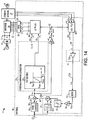
- FIG. 14 another exemplary motor drive controller embodiment 20 is shown in Fig. 14 , where a voltage-frequency control component 24 is used to generate a ⁇ -axis voltage command signal or value 35 ( v * ⁇ ).
- the signal or value 35 is converted by a ⁇ , ⁇ to a,b,c synchronous-to-stationary reference frame converter component 36 to provide stationary reference frame voltage command signals or values v a *, v b *, v c * to the pulse width modulation component 38 for generating switching control signals to operate the inverter 14.
- Other implementations are possible, instead using a current-frequency control component to generate current control command signals or values for use in pulse width modulation operation of the inverter 14.
- the angle ⁇ 43 is also provided to an a,b,c to ⁇ , ⁇ stationary-to-synchronous reference frame converter component 44 that receives the AC output current feedback signals or values 28 i a , i b and i c from the output of the inverter 14 via the current sensors 27, and converts these to the synchronous ⁇ , ⁇ reference frame by computing a ⁇ -axis estimated output current signal or value 46 (i ⁇ ).
- ⁇ -axis estimated output current signal or value 46 e.g., and also a ⁇ -axis value i ⁇ 48
- the controller 20 in this embodiment uses the transformed output current signal or value 46 to compute a frequency modulation value 25a ( ⁇ f *), and employs a summation component 29 to selectively adjust the frequency or speed setpoint value f * 21 (or a rate limited value f RL 31) to provide an adjusted frequency or speed setpoint value 31a ( f AD ) from which the voltage-frequency control component 24 computes the ⁇ -axis voltage command signal or value 35.
- the frequency modulation value 25a ( ⁇ f *) can be computed in any suitable fashion in whole or in part based on the AC output current feedback signal(s) or value(s) 28, 46 and the frequency modulation value 25a can be used to modify the original frequency or speed setpoint signal or value 21 and/or a rate limited signal or value 31 in any suitable fashion.
- the adjustment is performed by subtracting the frequency modulation value 25a from the frequency or speed setpoint signal or value 21 or 31 to provide the adjusted frequency or speed setpoint value 31a.
- a gain stage 52b can be provided, as shown in Fig. 14 , which is used to compute an estimated per unit output current signal or value 52a (i ⁇ _PU ) based on the estimated ⁇ -axis output current signal or value (46) in the synchronous ( ⁇ , ⁇ ) reference frame, and the frequency modulation signal or value 25a is computed at least partially based on the estimated per unit output current signal or value 52a.
- the estimated per unit output current signal or value i ⁇ _PU is high pass filtered via a filter component 55, thereby advantageously providing a filtered estimated per unit output current signal or value 55a with any DC components at least partially removed, thereby providing a signal 55a having AC components indicative of output current hunting or searching associated with large isolations in the rotor shaft of the motor 6 during starting for low frequency command input setpoints 21 and/or during rotor velocity isolation about the setpoint speed following load transitions or speed setpoint adjustments, particularly at low speeds.
- the filtered estimated signal or value 55a is provided as the frequency modulation signal or value 25a for adjusting the input setpoint signal or value 21, 31.
- the signal or value 55a can be amplified by a gain factor (K p ), and a limiter circuit 57 may be included to limit the range of the amplified signal in certain non-limiting embodiments.
- a multiplier 59 may be implemented to multiply the output of the limiter 57 by a sign signal from a sign function 58 based on the sign (positive or negative, i.e. forward or reverse) of the desired frequency or speed setpoint input signal or value 21.
- the output of the multiplier 59 in the illustrated embodiment provides the frequency modulation value 25a to the summing junction adjuster component 29 for adjustment of the received (and optionally rate limited) speed or frequency setpoint to provide the adjusted setpoint 31a.
- power conversion systems, control apparatus, methods and non-transitory computer readable mediums having computer-executable instructions are provided for sensorless motor speed control via sampling at least one AC output current feedback signal or value, computing a frequency modulation value based at least partially on the output current feedback and/or based on at least one voltage command or feedback signal or value, as well as adjusting a frequency or speed setpoint value at least partially based on the frequency modulation value and controlling an inverter according to the adjusted frequency or speed setpoint value.
Description
- The subject matter disclosed herein relates to power conversion, and more specifically to apparatus and techniques for sensorless motor control. Sensorless motor drives are used in a variety of applications, particularly where providing position and/or speed sensors directly at a motor load is difficult or impractical. A typical sensorless system employs a voltage-frequency (V/F, alternatively known as Volts per Hertz, V/Hz) controller providing a voltage setpoint according to a desired motor speed or frequency, and this form of sensorless control has been used primarily with induction motors. In certain applications, a step-up transformer may be used to boost the motor drive output voltage, allowing use of a low-voltage drive to power a medium voltage induction motor, and/or to reduce I2R losses and facilitate use of a smaller diameter cable wire for long cable runs between the motor drive and the driven motor. Certain applications also employ sine wave filters, such as LC filters to suppress reflected wave voltage spikes associated with pulse width modulated (PWM) variable frequency drives. Use of sensorless voltage-frequency control techniques, however, may lead to problems, particularly where a transformer and/or sine wave filter is connected between the motor drive and the motor load. Conventional sensorless field-oriented-control (FOC) or other open loop speed control techniques have thus been found generally unsuitable for low-speed motor drive operation where output filters and transformers are used, such as in electric submersible pumps (ESPs), and these difficulties are particularly problematic in driving permanent magnet synchronous motors (PMSMs). Moreover, voltage-frequency control in combination with a sine wave filter under starting conditions may result in the motor not being able to start, with large oscillations on the rotor shaft for low frequency commands. Motors in sensorless speed control applications also suffer from oscillation in rotor velocity about the setpoint speed following load transitions or speed setpoint adjustments, particularly at low speeds. In certain situations, moreover, the driven motor may be unable to successfully start from a stopped condition due to unstable motor speed oscillations. Thus, improved techniques and motor drives are needed for sensorless motor speed control, particularly for driving permanent magnet motors to provide improved stability control.
- MIRANDA R S ET AL, "Parameter and Speed Estimation for Implementing Low Speed Sensorless PMSM Drive System Based on an Algebraic Method", APPLIED POWER ELECTRONICS CONFERENCE, APEC 2007 - TWENTY SECOND ANNUAL IEEE, IEEE, PI, (20070201), ISBN 978-1-4244-0713-2, PAGE 1406 - 1410 discloses a sensorless control scheme for a surface-mounted permanent-magnet synchronous machine using the high frequency voltage signal injection method. The reactances of the high frequency model vary as a function of rotor position and a simple method based on measured high frequency currents and voltages is used to identify these reactances. Using such motor reactances, rotor position and velocity can be estimated. The proposed method is algebraic and does not require accurate knowledge of the initial value of the rotor position. The strategy was verified experimentally using a commercial surface-mounted permanent-magnet synchronous machine.
- It is the object of the present invention to provide an improved method for sensorless motor speed control, as well as a corresponding system.
- This object is solved by the subject matter of the independent claims. Preferred embodiments are defined by the dependent claims.
- Various aspects of the present disclosure are now summarized to facilitate a basic understanding of the disclosure, wherein this summary is not an extensive overview of the disclosure, and is intended neither to identify certain elements of the disclosure, nor to delineate the scope thereof. Rather, the primary purpose of this summary is to present various concepts of the disclosure in a simplified form prior to the more detailed description that is presented hereinafter. The present disclosure provides motor drive apparatus and control techniques by which improved motor speed stability can be facilitated, and finds particular utility in association with open loop or sensorless speed control applications involving asynchronous or synchronous motors, directly driven or in combination with output filters and/or output transformers. The disclosed techniques, moreover, can be employed in systems using voltage-frequency and/or current-frequency control algorithms.
- Methods are disclosed in accordance with one or more aspects of the present disclosure for sensorless motor speed control in a motor drive. The methods include sampling one or more AC output current feedback signals or values from the output of the motor drive inverter, and computing a frequency modulation value based on the output current feedback and/or on one or more voltage command or voltage feedback signals or values. In addition, the methods involve adjusting a frequency or speed setpoint value based in whole or in part on the frequency modulation value in order to provide an adjusted frequency or speed setpoint value, as well as controlling the motor drive inverter according to the adjusted frequency or speed setpoint value. The original speed or frequency setpoint may, in certain embodiments, be rate limited prior to adjustment according to the modulation value. In addition, the adjustment may involve subtracting the modulation value from the rate limited or original frequency or speed setpoint value. In certain embodiments, moreover, the modulation value computation may include computing an estimated motor performance value, such as estimated electromagnetic torque, torque angle, power factor, power factor angle, power, or error between the open loop angle and an estimated rotor position, or other performance value related to operation of the motor which can be estimated according to the current feedback and/or one or more voltage signals. In addition, the estimated motor performance value may be high pass filtered in certain embodiments to remove any DC offset prior to adjustment of the received speed or frequency setpoint.
- Motor drives are provided in accordance with further aspects of the disclosure, including an inverter which provides AC output power to drive a motor load, as well as a sensorless motor speed controller that provides switching control signals to operate the inverter based at least in part on a frequency or speed setpoint. The motor speed controller implements a signal generator which computes a frequency modulation value according to one or more AC output current feedback signals or values representing the output current of the inverter, and/or according to one or more voltage command signals or values used in controlling the inverter. In addition, the motor speed controller includes an adjustment component which adjusts the frequency or speed setpoint value based in whole or in part on the frequency modulation value in order to provide an adjusted frequency or speed setpoint value, as well as a command generator which provides switching control signals to the inverter at least partially according to the adjusted frequency or speed setpoint value.
- In certain embodiments, the signal generator computes an estimated motor performance value based on the AC output current feedback and/or on one or more voltage command or voltage feedback signals or values, and computes the frequency modulation value according to the estimated motor performance value. In addition, the motor speed controller may include a high pass filter for filtering the estimated motor performance value, and the resulting filtered estimated motor performance value is used in computing the frequency modulation value in certain embodiments. The signal generator in certain embodiments computes the estimated motor performance value as an estimated torque value, power factor value, power factor angle value or power value. In certain embodiments, the sensorless motor speed controller includes a rate limiter which operates to rate limit the frequency or speed setpoint, and the adjustment component subtracts the frequency modulation value from the rate limited frequency or speed setpoint value to provide the adjusted frequency or speed setpoint value for operating the inverter. The adjustment component in certain embodiments subtracts the frequency modulation value from the frequency or speed setpoint value in order to provide the adjusted frequency or speed setpoint.
- Further embodiments provide methods for motor drive control, including sampling one or more output current feedback signals or values from an inverter, computing a frequency modulation value at least partially according to the output current feedback signal or value, as well as adjusting a frequency or speed setpoint based at least partially on the frequency modulation value and controlling the inverter according to the adjusted frequency or speed setpoint value. In certain embodiments, the frequency or speed setpoint value is rate limited and the frequency modulation value is subtracted from the rate limited setpoint to provide the adjusted frequency or speed setpoint value. In certain embodiments an estimated per unit output current signal or value is computed according to the output current feedback signal or value, and the frequency modulation value is computed at least partially based on the estimated per unit output current signal or value. The output current feedback signal or value is high pass filtered in certain embodiments, and the frequency modulation value is computed at least partially according to the filtered estimated output current signal or value. In certain implementations, moreover, the filtered signal or value may be amplified by a gain factor to provide an amplified signal, and a range of the amplified signal is selectively limited, with the frequency modulation value being computed based at least partially on the range limited amplified signal.
- In certain embodiments, an estimated per unit output current signal or value is computed and the frequency modulation value is computed accordingly. The estimated per unit output current signal or value may be high pass filtered in certain embodiments, and the frequency modulation value is computed at least partially based on the filtered estimated per unit output current signal or value. The filtered estimated per unit output current signal or value may be amplified by a gain factor in certain embodiments and the range of the amplified signal may be selectively limited, with the frequency modulation value being computed at least partially based on the range limited amplified signal. In certain embodiments, the output current feedback signals or values are converted to a synchronous reference frame and the frequency modulation value is computed based at least partially on the estimated output current signal or value in the synchronous reference frame.
- Non-transitory computer readable mediums are provided in accordance with further aspects of the disclosure, having computer-executable instructions for sensorless motor speed control in a motor drive, including instructions for sampling at least one AC output current feedback signal or value, computing a frequency modulation value based on the output current feedback and/or based on at least one voltage command or feedback signal or value, as well as adjusting a frequency or speed setpoint value at least partially based on the frequency modulation value and controlling an inverter according to the adjusted frequency or speed setpoint value.
- Motor drives are provided according to further aspects of the disclosure, including an inverter and a sensorless motor speed controller with a signal generator that computes a frequency modulation value based on at least one AC output current feedback signal or value, an adjustment component that adjusts the frequency or speed setpoint value based at least partially on the frequency modulation value, and a command generator component which provides switching control signals to the inverter at least partially according to the adjusted frequency or speed setpoint value.
- The following description and drawings set forth certain illustrative implementations of the disclosure in detail, which are indicative of several exemplary ways in which the various principles of the disclosure may be carried out. The illustrated examples, however, are not exhaustive of the many possible embodiments of the disclosure. Other objects, advantages and novel features of the disclosure will be set forth in the following detailed description when considered in conjunction with the drawings, in which:
-
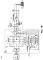
Fig. 1A is a schematic diagram illustrating an exemplary motor drive with a stability signal generator creating a frequency modulation value for adjusting a speed or frequency setpoint to create inverter switching control signals for enhanced stability in sensorless motor speed control according to one or more aspects of the present disclosure; -
Fig. 1B is a schematic diagram illustrating a motor drive with a stability signal generator used in sensorless speed control of a motor connected to the inverter output through a sine wave filter and a transformer; -
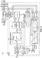
Fig. 2 is a schematic diagram illustrating an exemplary motor drive controller with a stability signal generator and a voltage-frequency control configuration; -
Fig. 3 is a schematic diagram illustrating another exemplary motor drive controller with the stability signal generator and a current-frequency controller; -
Fig. 4 is a schematic diagram illustrating yet another motor drive controller with a stability signal generator and a current-frequency controller with a reduced bandwidth proportional-integral (PI) controller for driving a motor through a sine wave filter and transformer; -
Fig. 5 is a schematic diagram illustrating an exemplary frequency modulation (FM) signal generator in the motor drive controller used for computing an estimated electromagnetic torque value based on estimated stator flux; -
Fig. 6 is a schematic diagram illustrating another exemplary frequency modulation signal generator used to compute an estimated electromagnetic torque value based on estimated rotor flux; -
Fig. 7 is a schematic diagram illustrating yet another FM signal generator which computes an estimated power factor value for selective adjustment of the speed or frequency setpoint; -
Fig. 8 is a schematic diagram illustrating another exemplary FM signal generator computing an estimated power factor angle for use in adjusting the speed or frequency setpoint; -
Fig. 9 is a schematic diagram illustrating still another FM signal generator computing an estimated power value for adjusting the speed or frequency setpoint; -
Fig. 10 is a graph illustrating a stationary reference frame transformation in the motor drive controller; -
Fig. 11 is a graph showing motor speed, current and load torque curves for the motor drive without stability control for a step load change; -
Fig. 12 is a graph showing motor speed, current and load torque curves for the motor drive using the stability control concepts of the present disclosure; -
Fig. 13 is a flow diagram illustrating an exemplary method for sensorless motor speed control in the motor drive in accordance with further aspects of the present disclosure; -
Fig. 14 is a schematic diagram illustrating another exemplary motor drive controller with a stability signal generator and a voltage-frequency control configuration; and -
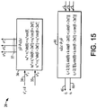
Fig. 15 is a schematic diagram illustrating exemplary transformations in the controller ofFig. 14 . - Referring now to the figures, several embodiments or implementations are hereinafter described in conjunction with the drawings, wherein like reference numerals are used to refer to like elements throughout, and wherein the various features are not necessarily drawn to scale.
- Reference is made to
US Patent Application serial no. 13/868,216, filed April 23, 2013 U.S. Patent Application Serial No. 13/931,839, filed on June 29, 2013 -
Methods 100 andmotor drive apparatus 10 are presented below for sensorless or open loop motor speed control using a stability signal generator as part of the motor drive controller. The control techniques and motor drives may be used in a variety of applications, including without limitation driving electric submersible pumps, whether including an induction motor or a permanent magnet synchronous motor (PMSM), and may be employed in situations in which the motor drive is directly connected to the driven motor or where one or more intervening components (e.g., sine wave filters and/or transformers) are connected between the output inverter and the driven motor. In addition, the concepts of the present disclosure may be employed in conjunction with any suitable form of control command algorithm, including without limitation voltage-frequency and/or current-frequency control, using any suitable internal closed loop feedback regulation configuration (e.g., proportional-integral or PI control components). The presently disclosed techniques, moreover, may be successfully employed to improve stability in operating permanent magnet and/or induction motors to avoid or mitigate undesirable "hunting" (oscillation) and/or undesired motor stopping or inability to start, particularly for low speed operation and/or in the presence of changes or perturbations in the load and/or desired setpoint operating speed. In this regard, while illustrated and described in various exemplary embodiments below, the various aspects of the present disclosure, and in particular the stability control techniques may be used in a wide variety of motor drive applications, motor drive controller architectures, etc., and the various concepts are not limited by the illustrated embodiments. - Referring initially to
Figs. 1A and1B , various exemplary motor drives 10 are presented hereinafter, in sensorless or open loop speed control configurations wherein no direct measurement of the motor speed or position is provided. While these circumstances are common in remotely driven motor situations (e.g., submersible pump applications, etc.), the various stability control aspects of the present disclosure may also be employed in systems in which the actual motor speed is directly measured and feedback signals are provided to the motor drive controller. As shown inFigs. 1A and1B , apower conversion system 2 generally includes anAC power source 4 providing single or multiphase power (e.g., 480 V AC, 50 or 60 Hz) to a motordrive power converter 10. Themotor drive 10, in turn, includes one or more power conversion stages with aninverter 14 providing single phase or multiphase AC output currents (e.g., three-phase output currents IA, IB and IC in the illustrated examples) to drive amotor load 6. As shown inFig. 1A , themotor load 6 may be directly driven by the output of themotor drive inverter 14, or one or more intervening circuits may be connected between theinverter 14 and themotor load 6, such as one or both of asine wave filter 16 and/or atransformer 18 and a potentially lengthy cable 8 as illustrated inFig. 1B . - The
drive 10 in these examples includes an active orpassive rectifier 12 providing rectification of the received (e.g., three-phase) AC input power to create a DC bus voltage across aDC link circuit 13 including a capacitance C. Any suitable form ofrectifier 12 can be used, including without limitation a passive rectifier (e.g., one or more rectifier diodes), or a switching rectifier operating at or near the fundamental frequency of the AC input source (fundamental front end or FFE) or at a higher and possibly variable switching frequency, such as an active front end (AFE) rectifier that performs additional functions such as power factor correction, etc. TheDC link circuit 13 provides a DC input voltage to a switchinginverter 14. Theinverter 14 in this example includes switching devices S1, S2, S3, S4, S5 and S6 operated according to inverterswitching control signals 22 from acontroller 20 to convert the DC power to AC output currents IA, IB and IC for driving themotor load 6. Although the illustratedinverter 14 provides a three-phase two-level output, other single or multiphase or multilevel output implementations are possible within the scope of the present disclosure. Any suitable inverter switching devices S1-S6 may be used, including without limitation insulated gate bipolar transistors (IGBTs), silicon controlled rectifiers (SCRs), gate turn-off thyristors (GTOs), integrated gate commutated thyristors (IGCTs), etc. Thecontroller 20 and the elements and components thereof can include suitable logic or processor-based circuitry, and may also include signal level amplification and/or driver circuitry (not shown) to provide suitable drive voltage and/or current levels sufficient to selectively actuate the switching devices S1-S6, for instance, such as comparators, carrier wave generators or digital logic/processor elements and signal drivers, etc. Moreover, thecontroller 20 can provide theswitching control signals 22 according to any suitable pulse width modulation technique, including without limitation space vector modulation (SVM), carrier-based pulse width modulation, selective harmonic elimination (SHE), etc. In addition, thecontroller 20 implements various computational functions as detailed hereinafter and may include suitable analog to digital and digital to analog conversion components and processor-based or otherwise programmable logic circuitry alone or in combination with analog circuitry to perform various operations on signals or values as described herein. Furthermore, certain embodiments of thecontroller 20 may include processing elements and electronic memory for storage of data and program instructions by which thecontroller 20 may implement the various methods (e.g.,method 100 below) detailed herein. - The
system 2 inFig. 1B further includes a sine wave oroutput filter 16, in one example, a three-phase LC filter having a series filter inductor LF in each output line, as well as a corresponding filter capacitor CF coupled between the corresponding phase line and a common connection point. Other output filter topologies may be used, such as LCL filters, CLC filters, etc. with one or more series elements and further filter elements (e.g., filter capacitors CF) connected in any suitable delta or Y configuration. The example ofFig. 1B also includes atransformer 18 between thefilter 16 and the motor cable 8. The illustratedtransformer 18 has a three phase delta-connected primary as well as a Y-connected secondary, although any suitable transformer primary and/or secondary winding configuration or topology may be used. Moreover, thetransformer 18 may in certain embodiments be a step-up transformer. For example, a step-uptransformer 18 may facilitate use of a low-voltage drive 10 to power a medium orhigh voltage motor 6, or allow use of a medium-voltage drive 10 to power a high-voltage motor 6. Also or in combination, a step-uptransformer 18 may be useful to allow a reduction in the current levels carried by the cable 8, thereby facilitating use of smaller diameter cable wires in the cable 8. The cable 8, moreover, can be of any suitable construction for interfacing the motor drive output, thesine wave filter 16, and/or thetransformer 18 with the leads of themotor 6. - The
motor drive 10 and thecontroller 20 operate in sensorless fashion to control one or more operating parameters of the drivenmotor load 6. For example, thecontroller 20 provides the inverterswitching control signals 22 in order to control position and/or speed and/or torque of themotor 6 without directly sensing any of these controlled parameters. In the illustrated implementation, for instance,current sensors 27 are disposed at the output of theinverter 14 to provide feedback signals or values 28 (e.g., ia, ib and ic) to thecontroller 20 which represent the inverter output currents IA, IB and IC, and/or from which the values of these output currents can be computed, derived or otherwise estimated. Any suitablecurrent sensing devices 27 can be used to generate or provide the signals and/orvalues 28, and may provideanalog signals 28 and/or thesensors 27 may be smart sensors providingdigital values 28 representing the output currents IA, IB and IC generated at the output of theinverter 14. - The
controller 20 uses the feedback signals orvalues 28 as well as one or more desired operating parameters to regulate or adjust the output currents IA, IB and IC. Overall, however, the control technique implemented by the illustratedcontroller 20 is essentially sensorless or open-loop with respect to the actual operating condition of the driven motor load 6 (e.g., speed and/or position), as there are no direct feedback signals obtained from themotor 6 itself. In the examples ofFigs. 1A and1B , for instance, thecontroller 20 receives the desired frequency or motor speed value f* 21 from a supervisory control system component (not shown), which may be a distributed control system (DCS) element, a user-adjustable knob, local user interface, etc. Thecontroller 20, moreover, includes a voltagecommand generator component 23, which can be a voltage-frequency 24 or current-frequency control component 24a (e.g.,Figs. 2-4 below). There may also be a closed loop controller such as a proportional-integral (PI)controller 26 which may be a reduced bandwidth PI controller in certain embodiments (e.g.,Fig. 4 below). In operation, thecontrol components Fig. 3 are used to regulate the inverter output currents IA, IB and IC by providing the inverterswitching control signals 22 according to the desired speed or frequency signal orvalue 21 and the feedback signals or values 28. - In addition, in accordance with one or more aspects of the present disclosure, the
controller 20 implements a stabilitysignal generator component 25 which computes afrequency modulation value 25a (e.g., Δf*) based on the current feedback signal or value ia, ib and ic as well as on one or more voltage command signals or values 37 va *, vb * and vc * used in controlling theinverter 14. As seen inFigs. 1A and1B , for instance, the voltagecommand generator component 23 internally generates the voltage commands va *, vb * and vc * and provides these to the stabilitysignal generator component 25 for generating thefrequency modulation value 25a. The sensorlessmotor speed controller 20 also includes an adjustment component 29 (e.g., a summer in one example) which adjusts the frequency orspeed setpoint value 21 based at least partially on thefrequency modulation value 25a to provide an adjusted frequency orspeed setpoint value 31a (e.g., f AD inFigs. 2-4 below), and thecommand generator 23 provides the switchingcontrol signals 22 to theinverter 14 at least partially according to the adjusted frequency orspeed setpoint value 31a. In the illustrated example, theadjustment component 29 subtracts thefrequency modulation value 25a from the frequency orspeed setpoint value 21 to provide the adjusted frequency orspeed setpoint value 31a. Other implementations are possible, in which anadjustment component 29 performs a different type of adjustment, such as offsetting, multiplication, division, addition, or combinations thereof, etc., wherein the concepts of the present disclosure are not limited to the illustrated subtraction example. - Referring also to
Figs. 2-4 ,Fig. 2 shows further details of an exemplarymotor drive controller 20 with astability signal generator 25 and a voltage-frequency control configuration implemented in thevoltage command generator 23. Thevoltage command generator 23 includes a voltage-frequency (V-F)control component 24 which receives the adjustedfrequency setpoint 31a from theadjustment component 29 and generates a δ-axis voltage setpoint (v*δ) 35 accordingly. Thecontroller 20 implements various components, for example, in processor-executed software or firmware, and operates on certain variables in a synchronous δ, γ reference frame, with received feedback signals orvalues 28 and generated switchingcontrol signals 22 being reference to a stationary (e.g., a, b, c) reference frame. In this regard, the illustrated δ, γ reference frame rotates at the same frequency as the conventional field commutation control (D, Q) reference frame, but the position need not be the same, with γ and δ somewhat analogous to "d" and "q", but they are not necessarily aligned (e.g., γ will likely be somewhere between the D axis and the Q axis, and γ and δ are orthogonal to one another). It is also understood that the described voltage and/or current regulation can be performed in other reference frames. The voltage-frequency control component 24 in the example ofFig. 2 provides avoltage setpoint output 35 based on the adjusted frequency or speed setpoint signal orvalue 31a. As seen inFig. 2 , moreover, arate limiter 30 may optionally be included to rate limit the frequency orspeed setpoint value 21 to provide a rate limited frequency or speed setpoint value 31 (f RL), and theadjustment component 29 in this example subtracts thefrequency modulation value 25a from the rate limited frequency orspeed setpoint value 31 to provide the adjusted frequency orspeed setpoint value 31a as an input to thecontrol component 24. - The illustrated voltage-
frequency control component 24 implements a multiple-range curve or function as illustrated, with the voltage-frequency relationship having a zero voltage value VBOOST corresponding to a zero frequency value (e.g., 0 Hz), and remains constant at VBOOST until a predetermined boost frequency FBOOST. The voltage-frequency relationship implemented by thecontrol component 24 also includes a second portion with increasing voltage values corresponding to a frequency range from the boost frequency FBOOST to a cutoff frequency value FCUT, as well as a higher portion with a constant voltage value (e.g., VMAX) corresponding to frequencies above the cutoff frequency FCUT, where VMAX can be the maximum rated output voltage of theinverter 14 in certain implementations, and the cutoff frequency FCUT is preferably set to correspond to the rated operating frequency of the motor 6 (e.g., about 60 Hz in one implementation). Thecontrol component 24 in certain embodiments can be implemented using a lookup table or a parametric function. The voltage-frequency output v*δ is the δaxis voltage setpoint 35. In the illustrated embodiment, thecontroller 23 operates according to a zero γ axis value 34 (v*γ = 0), although not a strict requirement of all implementations of the present disclosure. - As seen in
Figs. 2 and10 , moreover, the illustratedstability signal generator 25 includes stationary referenceframe converter components values 37 from the a,b,c reference frame to a stationary "α,β" reference frame by the illustrative transformation shown inFig. 10 . In this manner, theconverter 50 provides α,β reference frame current feedback signals iα and iβ, and theconverter 51 provides voltage command signals v α* and v β*, to a frequency modulation (FM)signal generator component 52. In the embodiment ofFig. 2 , moreover, thesignal generator component 25 employs the FMsignal generator component 52 to compute an estimatedmotor performance value 52a, in this case an estimated (per unit) torque value T̂pu , based on the AC output current feedback ia, ib, ic (converted to signals or values iα and iβ) and also based on the voltage command signals or values va *, vb *, vc * (e.g., converted signals or values v α* and v β*). In particular, thesignal generator 52 includes afirst component 53 which calculates estimated rotor flux linkage values λ̂αr , λ̂βr based on the output current feedback iα and iβ, the voltage commands v α* and v β*, and on an output load resistance value R corresponding to the resistance of themotor 6 and any intervening cable 8 according to the following formulas (1) and (2):

where L is the inductance of the motor and any intervening cable. - In addition, the
signal generator 52 includes asecond component 54 which is operative to compute the estimated torque value T̂pu based on the estimated rotor flux values λ̂αr and λ̂βr , as well as on the current feedback iα and iβ according to the following equation (3):
where P is the number of pole pairs in themotor 6 and Trated is the rated torque for themotor 6. In certain embodiments, the estimated torque value T̂pu can be computed using stator flux values, and may be computed according to rotor flux values in other embodiments. - The estimated torque or other estimated
motor performance value 52a is then used by thesignal generator component 25 to compute thefrequency modulation value 25a. As seen inFig. 2 , moreover, the illustrated embodiment includes ahigh pass filter 55 to filter the estimatedmotor performance value 52a to provide a filtered estimatedmotor performance value 55a, thereby removing undesirable DC offsets from the estimatedmotor parameter 52a. Thesignal generator 25 then computes theFM value 25a based at least partially on the filtered estimatedmotor performance value 55a. In the illustrated example, again component 56 is provided to amplify the filteredsignal 55a, and alimiter circuit 57 may be included to limit the range of the amplified signal. The illustrated embodiment also includes anoptional multiplier 59 which, for some embodiments of estimatedmotor performance value 52a, multiplies the output of thelimiter 57 by a sign signal from asign function 58 based on the sign (positive or negative, i.e. forward or reverse) of the desired frequency or speed setpoint input signal orvalue 21. The output of themultiplier 59 provides thefrequency modulation value 25a to the summingjunction adjuster component 29 for adjustment of the received (and optionally rate limited) speed or frequency setpoint to create the adjustedsetpoint 31a. - The adjusted
setpoint 31a provides an input to thevoltage command generator 23 and thecontrol component 24 thereof. TheV-F controller 24, moreover, provides γ and δ axis voltage setpoint signal or value outputs vγ * 34 and vδ * 35, respectively, which are converted to the stationary reference frame by a converter 36 (δ,γ to a,b,c) using a phase angle signal or value θ 43 obtained from the adjustedfrequency setpoint 31a via a multiplier 40 (2π) providing a frequency output 41 (ω) and anintegrator 42 to create theangle output 43. Thereference frame converter 36, in turn, provides the set of three stationary reference frame voltage setpoint signals or values 37 (va *, vb * and vc *) as inputs to a pulse width modulation (PWM)component 38 that includes any suitable form of modulation, isolation, amplifiers, gate driver circuitry, etc. to generate the inverterswitching control signals 22 for controlling theinverter 14 using known techniques. -
Fig. 3 illustrates anothercontroller embodiment 20 in which thestability signal generator 25 again provides thefrequency modulation signal 25a for stability control based on an estimatedtorque value 52a. In this case, however, thevoltage command generator 23 includes a current-frequency controller 24a along with aPI controller 26. In this case, moreover, an a,b,c to δ,γ converter 44 provides δ,γ current feedback signals iγ 48 and iδ 46 as inputs to thePI controller 26 for closed loop regulation with respect to its current setpoints iδ * 32 and iγ * 33 (=0). The current-frequency (I-F)control component 24a in this example receives the adjusted frequency orspeed setpoint 31a, and generates the δ-axis current setpoint (i*δ) 32 accordingly. In one possible implementation, the current-frequency control component 24a implements a dual-range curve or function as illustrated, with the current-frequency relationship being a zero current value corresponding to a zero frequency value (e.g., 0 Hz). As shown inFig. 3 , the current-frequency relationship implemented by thecontrol component 24a includes a first portion with increasing current values corresponding to a first frequency range from the zero frequency value to a cutoff frequency value FCUT, as well as a second portion with a constant current value (e.g., IMAX) corresponding to frequencies above the cutoff frequency FCUT, where IMAX can be the maximum rated output current of theinverter 14 in certain implementations, and the cutoff frequency FCUT is preferably set to correspond to a very low operating frequency of the motor 6 (e.g., about 0.5 - 1.0 Hz). The current-frequency control component 24a in certain embodiments can be implemented using a lookup table or a parametric function. In this regard, the current-frequency relationship includes the first ramped portion until the cutoff frequency, after which the maximum current is demanded, whereby thecontrol component 24a avoids sending DC current to any included output transformer 18 (e.g.,Fig. 4 below) at zero frequency. - The output (i*δ) of the current-
frequency controller 24a is the δ axiscurrent setpoint 32, which is provided to thePI control component 26. PI control is not a strict requirement of all embodiments of the present disclosure, wherein any suitable current regulating algorithm can be used to regulate the inverter output currents IA, IB and IC, and the PI algorithm in certain embodiments may have an algorithm bandwidth that is less than the resonant frequency of any included sine wave filter 16 (e.g.,Fig. 4 below). In the illustrated embodiment, thePI controller 26 operates according to a zero γ axis value 33 (i*γ = 0), although not a strict requirement of all implementations of the present disclosure. - In the example of
Fig. 3 , moreover, theFM signal generator 52 includescomponents motor performance value 52a as an estimated torque based on estimated stator flux linkage values via thecomponent 53 according to a motor resistance value Rmotor associated with the drivenmotor 6 according to the following equations (4) and (5):

where v α and v β are measured motor voltages after the a,b,c to α,βtransformation 51. In addition, thecomponent 54 computes the estimated torque value according to the following equation (6):
-
Fig. 4 shows anothermotor drive controller 20 with astability signal generator 25 and avoltage command generator 23 generating voltage commands, where the included PI controller is a reduced bandwidth proportional-integral controller for driving amotor 6 through asine wave filter 16 andtransformer 18. As in the examples above, moreover, thesignal generator 25 computes an estimated per unit torque value T̂pu for deriving thefrequency modulation value 25a. The inventors have appreciated that limiting the bandwidth of thePI controller 26 avoids or mitigates large inrush current during power up, particularly where thedrive 10 is providing output currents through asine wave filter 16 and/ortransformer 18. In certain applications, for instance, thesine wave filter 16 makes the inverter output particularly susceptible to large inrush currents, and limiting the bandwidth of the PI controller 26 (or other current regulation control algorithm implemented by the controller 20) to be well below the sine wave filter resonant frequency helps to mitigate or avoid high inrush current levels, particularly at power up. - Referring also to
Figs. 5-9 , the above described examples use a frequencymodulation signal generator 52 that computes estimatedtorque values 52a which are optionally high pass filtered using thefilter 55 and scaled and limited appropriately via thecomponents components frequency modulation value 25a. Various other embodiments are possible, some of which are illustrated inFigs. 5-9 , in which thevalue 25a is derived based on a different estimatedmotor performance value 52a. For example,Fig. 5 illustrates an example based on per unit electromagnetic torque computed using stator flux values computed from measured currents and commanded voltages using thecomponent 53, andFig. 6 shows an example of a per unit estimated torque value computed from measured currents and measured voltages according to computed rotor flux estimate values. As seen inFig. 7 , another possible implementation provides an estimatedpower factor value 52a (PF) computed from measured currents and measured voltages according to real and imaginary power values P and Q from thecomponent 53.Fig. 8 shows an implementation in which these real and imaginary power values are computed from measured currents and commanded voltages by thecomponent 53, and thecomponent 54 computes an estimated power factorangle value θ PF 52a. Yet another example is shown inFig. 9 , in which theFM signal generator 52 provides a per-unitpower estimate value 52a (Ppu ) upon which thefrequency modulation value 25a computation is performed. Other possible examples include computation of an estimatedperformance value 52a as an error between the open loop angle and an estimated rotor position. - Referring now to
Figs. 11 and 12 ,graphs motor speed 62, 72, current 64, 74 andload torque motor drive 10 without and with the stability control concepts of the present disclosure for a step load change. As seen in thegraph 60 ofFig. 11 , absent the stability control advantages achieved by the frequency modulation adjustment concepts discussed above, and particularly for low motor speeds, the onset of a step load increase in the load torque causes the open loop (sensorless) operation to suffer from potentially significant instability or "hunting" in themotor speed curve 62, resulting in oscillation in theload torque curve 66. InFig. 12 , however, thegraph 70 shows that the load torque increase incurve 76 results in a temporary drop and subsequent controlled recovery in the motor speed curve 72 (assuming a constant desired motor speed setpoint value). In this regard, the controlled modulation of the frequency setpoint via the adjustedfrequency setpoint value 31a effectively counteracts the effects of instability or hunting by compensation through the essentially out of phasefrequency modulation signal 25a. In this manner, instability is mitigated, thereby preventing or reducing the likelihood of excessive motor speed or position hunting and reducing the potential for undesired motor stoppage. - Referring also to
Fig. 13 , amethod 100 is presented for sensorless motor speed control in a motor drive (e.g.,motor drive 10 above). Although theexemplary method 100 is depicted and described in the form of a series of acts or events, it will be appreciated that the various methods of the disclosure are not limited by the illustrated ordering of such acts or events except as specifically set forth herein. In this regard, except as specifically provided hereinafter, some acts or events may occur in different order and/or concurrently with other acts or events apart from those illustrated and described herein, and not all illustrated steps may be required to implement a process or method in accordance with the present disclosure. The illustrated methods may be implemented in hardware, processor-executed software, or combinations thereof, in order to provide sensorless motor control as described herein, and various embodiments or implementations include non-transitory computer readable mediums having computer-executable instructions performing the illustrated and described methods. For instance, themethod 100 may be implemented using one or more processors associated with thecontroller 20, by executing instructions stored in an electronic memory operatively associated with thecontroller 20. - The
method 100 begins at 102 inFig. 13 , with receipt of the frequency or speed setpoint f* (e.g., 21 above) representing the desired operating speed of themotor load 6. Thesetpoint 21 can be received at 102 from any suitable source, such as an input from another element in a distributed control system, user interface, etc. At 104, one or more inverter output currents are measured or sampled (e.g., feedback signals 28 representing the three-phase output currents ia, ib, ic provided by theinverter 14 and sensed using thecurrent sensors 27 above). The sampled output currents, moreover, can be directly proportional to the actual measured inverter output currents, or thesignals 28 can be filtered, shifted, or otherwise undergo any suitable signal processing such that thevalues 28 represent the current output provided by theinverter 14 to facilitate computation of one or more estimated motor operating parameters as discussed above. At 106 inFig. 13 , a frequency modulation value is computed (e.g., Δf* signal orvalue 25a above) at least partially according to the AC output current feedback and also according to one or more voltage command signals or values (e.g., va *, vb *, vc * above). In this regard, the voltage command signals or values can be any voltage command setpoints in any suitable reference frame (e.g., stationary reference frame, synchronous reference frame, etc.) which are used or usable for controlling operation of the inverter. In one example, for instance, the previously computed voltage command signals or values va *, vb *, vc * used in a previous control cycle can be used in computing the estimated motor operating parameter for use in offsetting the frequency or speed setpoint for the next or subsequent control cycle. At 108, the frequency or speed setpoint 21 (f*), whether previously rate limited or not (e.g., rate limitedfrequency setpoint f RL 31 above), is adjusted at least partially according to the frequency modulation value Δf*, for example, by subtracting the frequency modulation value Δf* from the original or rate limited frequency orspeed setpoint inverter 14 is controlled at 110, after which theprocess 100 repeats as shown. - Referring now to
Figs. 14 and15 , another exemplary motordrive controller embodiment 20 is shown inFig. 14 , where a voltage-frequency control component 24 is used to generate a δ-axis voltage command signal or value 35 (v*δ). The signal orvalue 35 is converted by a γ,δ to a,b,c synchronous-to-stationary referenceframe converter component 36 to provide stationary reference frame voltage command signals or values va *, vb *, vc * to the pulsewidth modulation component 38 for generating switching control signals to operate theinverter 14. Other implementations are possible, instead using a current-frequency control component to generate current control command signals or values for use in pulse width modulation operation of theinverter 14.Fig. 15 illustrates one non-limiting example of transformation equations in theconverter component 36 to provide the δ-axis voltage command signal or value 35 (using v* γ = 0), using a phase angle θ obtained from an adjusted frequency setpoint signal orvalue 31a via again stage 40 multiplying the adjusted frequency signal orvalue 31a by 2π to obtain a frequency signal or value 41 (ω in radians) and anintegrator component 42 provides the angle θ according to the following equations (7)-(9):


- In the example of
Fig. 14 , moreover, the angle θ 43 is also provided to an a,b,c to γ,δ stationary-to-synchronous referenceframe converter component 44 that receives the AC output current feedback signals or values 28 ia, ib and ic from the output of theinverter 14 via thecurrent sensors 27, and converts these to the synchronous γ,δ reference frame by computing a δ-axis estimated output current signal or value 46 (iδ).Fig. 15 illustrates an exemplary implementation of the stationary-two-synchronousreference frame converter 44, with which the δ-axis estimated output current signal or value 46 (e.g., and also a γ-axis value iγ 48) can be computed in thecontroller 20, according to the following equations (10) and (11):

- The
controller 20 in this embodiment uses the transformed output current signal orvalue 46 to compute afrequency modulation value 25a (Δf*), and employs asummation component 29 to selectively adjust the frequency or speed setpoint value f* 21 (or a rate limited value f RL 31) to provide an adjusted frequency orspeed setpoint value 31a (f AD) from which the voltage-frequency control component 24 computes the δ-axis voltage command signal orvalue 35. In this embodiment, thefrequency modulation value 25a (Δf*) can be computed in any suitable fashion in whole or in part based on the AC output current feedback signal(s) or value(s) 28, 46 and thefrequency modulation value 25a can be used to modify the original frequency or speed setpoint signal orvalue 21 and/or a rate limited signal orvalue 31 in any suitable fashion. In one possible embodiment, the adjustment is performed by subtracting thefrequency modulation value 25a from the frequency or speed setpoint signal orvalue speed setpoint value 31a. - In various embodiments, moreover, a
gain stage 52b can be provided, as shown inFig. 14 , which is used to compute an estimated per unit output current signal orvalue 52a (iδ_PU) based on the estimated δ-axis output current signal or value (46) in the synchronous (δ, γ) reference frame, and the frequency modulation signal orvalue 25a is computed at least partially based on the estimated per unit output current signal orvalue 52a. In the illustrated embodiment, moreover, the estimated per unit output current signal or value iδ_PU is high pass filtered via afilter component 55, thereby advantageously providing a filtered estimated per unit output current signal orvalue 55a with any DC components at least partially removed, thereby providing asignal 55a having AC components indicative of output current hunting or searching associated with large isolations in the rotor shaft of themotor 6 during starting for low frequencycommand input setpoints 21 and/or during rotor velocity isolation about the setpoint speed following load transitions or speed setpoint adjustments, particularly at low speeds. - In certain implementations, the filtered estimated signal or
value 55a is provided as the frequency modulation signal orvalue 25a for adjusting the input setpoint signal orvalue value 55a can be amplified by a gain factor (Kp), and alimiter circuit 57 may be included to limit the range of the amplified signal in certain non-limiting embodiments. In certain embodiments, amultiplier 59 may be implemented to multiply the output of thelimiter 57 by a sign signal from asign function 58 based on the sign (positive or negative, i.e. forward or reverse) of the desired frequency or speed setpoint input signal orvalue 21. The output of themultiplier 59 in the illustrated embodiment provides thefrequency modulation value 25a to the summingjunction adjuster component 29 for adjustment of the received (and optionally rate limited) speed or frequency setpoint to provide the adjustedsetpoint 31a. - As illustrated and described above, power conversion systems, control apparatus, methods and non-transitory computer readable mediums having computer-executable instructions are provided for sensorless motor speed control via sampling at least one AC output current feedback signal or value, computing a frequency modulation value based at least partially on the output current feedback and/or based on at least one voltage command or feedback signal or value, as well as adjusting a frequency or speed setpoint value at least partially based on the frequency modulation value and controlling an inverter according to the adjusted frequency or speed setpoint value.
Claims (13)
- A method (100) for sensorless motor speed control in a motor drive (10), the method (100) comprising:sampling (104) at least one AC output current feedback signal or value (ia, ib, ic) from an output of an inverter (14) of the motor drive (10); characterized by computing (106) a frequency modulation value (25a) based on the at least one AC output current feedback signal or value (ia, ib, ic) and on at least one voltage command (Va*, Vb*, Vc*) orfeedback signal or value (Va, Vb , Vc );adjusting (108) a frequency or speed setpoint value (21, 31) based at least partially on the frequency modulation value (25a) to provide an adjusted frequency or speed setpoint value (31a); andcontrolling (110) the inverter (14) according to the adjusted frequency or speed setpoint value (31a).
- The method (100) of claim 1, wherein adjusting (108) the frequency or speed setpoint value (21, 31) comprises:rate limiting the frequency or speed setpoint value (21) to provide a rate limited frequency or speed setpoint value (31); andsubtracting the frequency modulation value (25a) from the rate limited frequency or speed setpoint value (31) to provide the adjusted frequency or speed setpoint value (31a).
- The method (100) of claim 1 or 2, wherein computing (106) the frequency modulation value (25a) comprises:high pass filtering the estimated per unit output current signal or value (iδ_PU) to provide a filtered estimated per unit output current signal or value (55a); andcomputing (106) the frequency modulation value (25a) based at least partially on the filtered estimated per unit output current signal or value (55a).
- The method (100) of any one of claims 1 to 3, wherein computing (106) the frequency modulation value (25a) comprises:amplifying the filtered estimated per unit output current signal or value by a gain factor (Kp) to provide an amplified signal;selectively limiting a range of the amplified signal to provide a range limited amplified signal; andcomputing (106) the frequency modulation value (25a) based at least partially on the range limited amplified signal.
- The method (100) of any one of claims 1 to 4, wherein adjusting (108) the frequency or speed setpoint value (21, 31) comprises subtracting the frequency modulation value (25a) from the frequency or speed setpoint value (21, 31) to provide the adjusted frequency or speed setpoint value (31a).
- The method (100) of any one of claims 1 to 5, wherein computing (106) the frequency modulation value (25a) comprises:computing an estimated per unit output current signal or value (iδ_PU) based on the at least one AC output current feedback signal or value (ia, ib, ic); andcomputing (106) the frequency modulation value (25a) based at least partially on the estimated per unit output current signal or value (iδ_PU).
- The method (100) of claim 1, further comprising prior to the sampling step:
receiving (102) a frequency or speed setpoint value (21, 31) representing a desired motor speed for a driven motor (6) . - The method (100) of any one of claims 2, 5 or 7, wherein computing (106) the frequency modulation value (25a) comprises:computing an estimated motor performance value (52a) based on the at least one AC output current feedback signal or value (ia, ib, ic) and on the at least one voltage command or feedback signal or value (Va , Vb , Vc );computing (106) the frequency modulation value (25a) based at least partially on the estimated motor performance value (55a).
- The method (100) of claim 7, wherein computing (106) the frequency modulation value (25a) comprises:high pass filtering the estimated motor performance value (52a) to provide a filtered estimated motor performance value (55a); andcomputing (106) the frequency modulation value (25a) based at least partially on the filtered estimated motor performance value (55a).
- The method (100) of claim 8, wherein computing the estimated motor performance value (52a) comprises computing at least one of an estimated power factor value, an estimated power factor angle value, and an estimated power value, and wherein the frequency modulation value (25a) is computed at least partially according to the at least one estimated power factor value, power factor angle value, or power value.
- A motor drive (10), comprising:an inverter (14) including a plurality of switching devices (S1-S6) operable according to switching control signals (22) to provide AC output power to drive a motor load (6); anda sensorless motor speed controller (20) providing the switching control signals (22) to the inverter (14) to regulate the AC output power at least partially according to a frequency or speed setpoint value (21, 31), characterized in that the sensorless motor speed controller (20) comprising:a signal generator component (25) configured to compute a frequency modulation value (25a) based on at least one AC output current feedback signal or value (ia, ib, ic) representing at least one AC output current of the inverter (14) and on at least one voltage command (Va*, Vb*, Vc*) or feedback signal or value (Va, Vb, Vc ) used in controlling the inverter (14),an adjustment component (29) configured to adjust the frequency or speed setpoint value (21, 31) based at least partially on the frequency modulation value (25a) to provide an adjusted frequency or speed setpoint value (31a), anda command generator component (23) configured to provide the switching control signals (22) to the inverter (14) at least partially according to the adjusted frequency or speed setpoint value (31a).
- The motor drive (10) of claim 11, wherein the signal generator component (25) is operative to compute an estimated motor performance value (52a) based on the at least one AC output current feedback signal or value (ia, ib, ic) and on the at least one voltage command or feedback signal or value (Va, Vb, Vc ), and to compute the frequency modulation value (25a) based at least partially on the estimated motor performance value (55a).
- The motor drive (10) of claim 11 or 12, wherein the adjustment component (29) is operative to subtract the frequency modulation value (25a) from the frequency or speed setpoint value (21, 31) to provide the adjusted frequency or speed setpoint value (31a).
Applications Claiming Priority (2)
| Application Number | Priority Date | Filing Date | Title |
|---|---|---|---|
| US13/931,839 US9054611B2 (en) | 2013-06-29 | 2013-06-29 | Method and apparatus for stability control of open loop motor drive operation |
| US14/193,329 US9287812B2 (en) | 2013-06-29 | 2014-02-28 | Method and apparatus for stability control of open loop motor drive operation |
Publications (3)
| Publication Number | Publication Date |
|---|---|
| EP2838193A2 EP2838193A2 (en) | 2015-02-18 |
| EP2838193A3 EP2838193A3 (en) | 2015-07-29 |
| EP2838193B1 true EP2838193B1 (en) | 2018-10-17 |
Family
ID=51205165
Family Applications (1)
| Application Number | Title | Priority Date | Filing Date |
|---|---|---|---|
| EP14173909.4A Active EP2838193B1 (en) | 2013-06-29 | 2014-06-25 | Method and apparatus for stability control of open loop motor drive operation |
Country Status (4)
| Country | Link |
|---|---|
| US (1) | US9287812B2 (en) |
| EP (1) | EP2838193B1 (en) |
| CN (1) | CN104253572B (en) |
| BR (1) | BR102014015638B1 (en) |
Families Citing this family (30)
| Publication number | Priority date | Publication date | Assignee | Title |
|---|---|---|---|---|
| US9054621B2 (en) | 2013-04-23 | 2015-06-09 | Rockwell Automation Technologies, Inc. | Position sensorless open loop control for motor drives with output filter and transformer |
| US10158314B2 (en) | 2013-01-16 | 2018-12-18 | Rockwell Automation Technologies, Inc. | Feedforward control of motor drives with output sinewave filter |
| US9490738B2 (en) | 2013-01-16 | 2016-11-08 | Rockwell Automation Technologies, Inc. | Sensorless motor drive vector control |
| EP2887538B1 (en) * | 2013-12-20 | 2016-03-16 | Baumüller Nürnberg GmbH | Method for controlling and regulating an electromagnetic machine |
| US9689383B2 (en) * | 2014-05-30 | 2017-06-27 | Rotating Right Inc. | Controller for use with a reciprocating electric submersible pump |
| US20160141878A1 (en) * | 2014-11-05 | 2016-05-19 | John Anton Johansen | Dc appliance system |
| US9716460B2 (en) | 2015-01-28 | 2017-07-25 | Rockwell Automation Technologies, Inc. | Method and apparatus for speed reversal control of motor drive |
| US9774284B2 (en) | 2015-02-19 | 2017-09-26 | Rockwell Automation Technologies, Inc. | Rotor position estimation apparatus and methods |
| JP6614825B2 (en) * | 2015-06-30 | 2019-12-04 | 日立ジョンソンコントロールズ空調株式会社 | Power conversion device, motor drive device, refrigeration device |
| JP2017085720A (en) * | 2015-10-26 | 2017-05-18 | 株式会社明電舎 | Position sensorless control device for permanent magnet synchronous motor |
| US9800190B2 (en) | 2016-02-03 | 2017-10-24 | Rockwell Automation Technologies, Inc. | Control of motor drives with output sinewave filter capacitor current compensation using sinewave filter transfer function |
| US9985565B2 (en) | 2016-04-18 | 2018-05-29 | Rockwell Automation Technologies, Inc. | Sensorless motor drive vector control with feedback compensation for filter capacitor current |
| EP3309955A1 (en) * | 2016-10-11 | 2018-04-18 | Siemens Aktiengesellschaft | Operation of a converter for coupling an electrical machine designed for operation on ac voltage with ac voltage power |
| US10020766B2 (en) | 2016-11-15 | 2018-07-10 | Rockwell Automation Technologies, Inc. | Current control of motor drives with output sinewave filter |
| US10528023B2 (en) * | 2016-12-22 | 2020-01-07 | General Dynamics-OTS. Inc. | Electric motor drive system for low-voltage motor |
| WO2018140902A1 (en) | 2017-01-27 | 2018-08-02 | Franklin Electric Co., Inc. | Motor drive system including removable bypass circuit and/or cooling features |
| CN110383672A (en) * | 2017-03-03 | 2019-10-25 | 日本电产株式会社 | Motor control method, motor control system and electric boosting steering system |
| CN108631680B (en) * | 2017-03-22 | 2022-06-03 | 操纵技术Ip控股公司 | Permanent magnet synchronous machine and method for determining position of motor by using vibration induction salient pole |
| US10784807B2 (en) * | 2017-05-11 | 2020-09-22 | Siemens Aktiengesellschaft | Methods and systems for controlling an electrical machine |
| JP7045841B2 (en) * | 2017-12-08 | 2022-04-01 | 株式会社ディスコ | Cutting equipment |
| CN108616141B (en) * | 2018-03-13 | 2021-07-06 | 上海交通大学 | Control method for LCL grid-connected inverter power nonlinearity in microgrid |
| CN108429503A (en) * | 2018-03-20 | 2018-08-21 | 美的集团股份有限公司 | The drive control method, apparatus and computer storage media of induction machine |
| EP3641128A1 (en) * | 2018-10-17 | 2020-04-22 | ABB Schweiz AG | Method of controlling a motor |
| CN111211715B (en) * | 2018-11-22 | 2023-04-25 | 杭州先途电子有限公司 | Motor control method and system and controller |
| CA3077885C (en) * | 2019-04-04 | 2023-08-29 | Toshiba International Corporation | Voltage optimization technique for a permanent magnet motor used in an electric submersible pump |
| US10707774B1 (en) * | 2019-05-10 | 2020-07-07 | Hamilton Sundstrand Corporation | Inverter controller of a voltage regulator of a power circuit |
| US11817797B2 (en) * | 2019-08-20 | 2023-11-14 | Toshiba Mitsubishi- Electric Industrial Systems | DC-AC converter with inrush current suppression |
| WO2021086389A1 (en) | 2019-10-31 | 2021-05-06 | Halliburton Energy Services, Inc. | Measurement guided oscillation detection for motor protection |
| CN115208262A (en) | 2021-04-08 | 2022-10-18 | 台达电子工业股份有限公司 | Motor control device and motor control method |
| US11539283B1 (en) * | 2021-06-04 | 2022-12-27 | Rockwell Automation Technologies, Inc. | System and method for reducing delay in the modulation of a multi-phase output voltage from an inverter |
Family Cites Families (34)
| Publication number | Priority date | Publication date | Assignee | Title |
|---|---|---|---|---|
| US3723840A (en) | 1972-01-21 | 1973-03-27 | Power Control Corp | Apparatus for motor current minimization |
| JPH0746917B2 (en) | 1987-07-28 | 1995-05-17 | 三菱電機株式会社 | Control device for three-phase converter |
| US5744921A (en) | 1996-05-02 | 1998-04-28 | Siemens Electric Limited | Control circuit for five-phase brushless DC motor |
| US5909098A (en) | 1996-05-02 | 1999-06-01 | Reda Pump | Downhole pumping system with variable speed pulse-width modulated inverter coupled to electrical motor via non-gap transformer |
| US6124697A (en) | 1997-08-20 | 2000-09-26 | Wilkerson; Alan W. | AC inverter drive |
| US5959431A (en) | 1997-10-03 | 1999-09-28 | Baldor Electric Company | Method and apparatus for instability compensation of V/Hz pulse width modulation inverter-fed induction motor drives |
| US6121736A (en) * | 1998-07-10 | 2000-09-19 | Matsushita Electric Industrial Co., Ltd. | Control apparatus for motor, and motor unit having the control apparatus |
| JP3396440B2 (en) | 1999-02-08 | 2003-04-14 | 株式会社日立製作所 | Control device for synchronous motor |
| JP3483805B2 (en) | 1999-07-05 | 2004-01-06 | 株式会社東芝 | Step-out detection device for sensorless brushless motor |
| US6208537B1 (en) | 1999-09-28 | 2001-03-27 | Rockwell Technologies, Llc | Series resonant sinewave output filter and design methodology |
| JP4131079B2 (en) * | 2000-07-12 | 2008-08-13 | 株式会社安川電機 | Inverter device and current limiting method thereof |
| CN2513286Y (en) | 2001-11-01 | 2002-09-25 | 哈尔滨工业大学 | Adjustable filter for converter output |
| JP4370754B2 (en) | 2002-04-02 | 2009-11-25 | 株式会社安川電機 | Sensorless control device and control method for AC motor |
| JP4112930B2 (en) | 2002-09-04 | 2008-07-02 | 東芝三菱電機産業システム株式会社 | Inverter device |
| ATE349102T1 (en) | 2004-09-09 | 2007-01-15 | Abb Oy | CONTROL WITHOUT SPEED SENSOR OF AN INDUCTION MACHINE USING A PBM INVERTER WITH LC OUTPUT FILTER |
| US7102323B2 (en) | 2004-11-30 | 2006-09-05 | Honeywell International Inc. | High power density/limited DC link voltage synchronous motor drive |
| US7932693B2 (en) | 2005-07-07 | 2011-04-26 | Eaton Corporation | System and method of controlling power to a non-motor load |
| JP4895703B2 (en) | 2006-06-28 | 2012-03-14 | 三洋電機株式会社 | Motor control device |
| US7724549B2 (en) | 2006-09-22 | 2010-05-25 | Rockwell Automation Technologies, Inc. | Integrated power conditioning system and housing for delivering operational power to a motor |
| JP5239235B2 (en) * | 2006-10-13 | 2013-07-17 | 日産自動車株式会社 | Power conversion device and power conversion method |
| US7979223B2 (en) | 2007-06-15 | 2011-07-12 | University Of South Carolina | Systems and methods for power hardware in the loop testing |
| JP5130031B2 (en) | 2007-12-10 | 2013-01-30 | 株式会社日立製作所 | Position sensorless control device for permanent magnet motor |
| ITBO20080047A1 (en) | 2008-01-25 | 2009-07-26 | Spal Automotive Srl | ELECTRIC DRIVE AND PILOT METHOD OF THE SAME. |
| EP2284986A4 (en) | 2008-04-28 | 2017-05-03 | Daikin Industries, Ltd. | Inverter control device and power conversion device |
| JP2010028894A (en) * | 2008-07-15 | 2010-02-04 | Nec Electronics Corp | Motor driving apparatus and control method thereof |
| US8009450B2 (en) | 2008-08-26 | 2011-08-30 | Rockwell Automation Technologies, Inc. | Method and apparatus for phase current balance in active converter with unbalanced AC line voltage source |
| US7990097B2 (en) | 2008-09-29 | 2011-08-02 | Rockwell Automation Technologies, Inc. | Power conversion system and method for active damping of common mode resonance |
| CN100586003C (en) * | 2008-10-17 | 2010-01-27 | 清华大学 | Vector control method for speed-free sensor for AC asynchronous motor |
| WO2010103627A1 (en) * | 2009-03-11 | 2010-09-16 | 三菱電機株式会社 | Controller of ac rotating machine |
| CN201504207U (en) | 2009-08-20 | 2010-06-09 | 中冶南方(武汉)自动化有限公司 | AC drive system with energy feedback |
| US8288886B2 (en) | 2009-11-09 | 2012-10-16 | GM Global Technology Operations LLC | Method and apparatus for avoiding electrical resonance in a vehicle having a shared high-voltage bus |
| CN101950983A (en) | 2010-10-08 | 2011-01-19 | 天津理工大学 | Two-stage photovoltaic grid-connected control system based on combination of pole allocation and repetitive control |
| WO2012060357A1 (en) * | 2010-11-05 | 2012-05-10 | 三菱電機株式会社 | Power converter |
| CN202872721U (en) | 2011-12-01 | 2013-04-10 | 国电南京自动化股份有限公司 | Vector control system free of speed sensor and based on cascade high voltage frequency converter |
-
2014
- 2014-02-28 US US14/193,329 patent/US9287812B2/en active Active
- 2014-06-24 BR BR102014015638-0A patent/BR102014015638B1/en active IP Right Grant
- 2014-06-25 EP EP14173909.4A patent/EP2838193B1/en active Active
- 2014-06-27 CN CN201410302737.9A patent/CN104253572B/en active Active
Non-Patent Citations (1)
| Title |
|---|
| None * |
Also Published As
| Publication number | Publication date |
|---|---|
| CN104253572A (en) | 2014-12-31 |
| EP2838193A3 (en) | 2015-07-29 |
| BR102014015638A2 (en) | 2016-11-29 |
| US20150002067A1 (en) | 2015-01-01 |
| EP2838193A2 (en) | 2015-02-18 |
| US9287812B2 (en) | 2016-03-15 |
| CN104253572B (en) | 2017-04-12 |
| BR102014015638B1 (en) | 2021-08-31 |
Similar Documents
| Publication | Publication Date | Title |
|---|---|---|
| EP2838193B1 (en) | Method and apparatus for stability control of open loop motor drive operation | |
| US9054611B2 (en) | Method and apparatus for stability control of open loop motor drive operation | |
| EP2797220B1 (en) | Position sensorless open loop control for motor drives with output filter and transformer | |
| US9374028B2 (en) | Transition scheme for position sensorless control of AC motor drives | |
| EP2858233B1 (en) | High dynamic control apparatus for current source converter background | |
| EP2043241B1 (en) | Motor Drive Using Flux Adjustment to Control Power Factor | |
| US9998058B2 (en) | Control apparatus for AC motor | |
| EP3054584B1 (en) | Method and apparatus for speed reversal control of motor drive | |
| US9985565B2 (en) | Sensorless motor drive vector control with feedback compensation for filter capacitor current | |
| Lin et al. | Infinite speed drives control with MTPA and MTPV for interior permanent magnet synchronous motor | |
| JP3586078B2 (en) | Power converter | |
| EP3136586B1 (en) | Sensorless motor drive vector control with feedback compensation for filter capacitor current | |
| JP7329735B2 (en) | motor controller | |
| JP6726839B2 (en) | Inverter control device | |
| CN111801886B (en) | Power conversion device | |
| WO2016035434A1 (en) | Motor drive device | |
| Shinagawa et al. | Harmonics reduction control of source current of electrolytic capacitorless inverter for position-sensorless drive system of induction motors | |
| CN111034022A (en) | Power conversion device and control method thereof | |
| EP4350973A1 (en) | Stable and passive observer-based v/hz control for synchronous motors | |
| JP2014027804A (en) | Power conversion device | |
| WO2023226011A1 (en) | Controlling of variable dc bus voltage in a motor | |
| JP5334920B2 (en) | Load drive device |
Legal Events
| Date | Code | Title | Description |
|---|---|---|---|
| 17P | Request for examination filed |
Effective date: 20140625 |
|
| AK | Designated contracting states |
Kind code of ref document: A2 Designated state(s): AL AT BE BG CH CY CZ DE DK EE ES FI FR GB GR HR HU IE IS IT LI LT LU LV MC MK MT NL NO PL PT RO RS SE SI SK SM TR |
|
| AX | Request for extension of the european patent |
Extension state: BA ME |
|
| PUAI | Public reference made under article 153(3) epc to a published international application that has entered the european phase |
Free format text: ORIGINAL CODE: 0009012 |
|
| PUAL | Search report despatched |
Free format text: ORIGINAL CODE: 0009013 |
|
| AK | Designated contracting states |
Kind code of ref document: A3 Designated state(s): AL AT BE BG CH CY CZ DE DK EE ES FI FR GB GR HR HU IE IS IT LI LT LU LV MC MK MT NL NO PL PT RO RS SE SI SK SM TR |
|
| AX | Request for extension of the european patent |
Extension state: BA ME |
|
| RIC1 | Information provided on ipc code assigned before grant |
Ipc: H02P 21/00 20060101AFI20150619BHEP Ipc: H02P 6/08 20060101ALI20150619BHEP |
|
| R17P | Request for examination filed (corrected) |
Effective date: 20160128 |
|
| RBV | Designated contracting states (corrected) |
Designated state(s): AL AT BE BG CH CY CZ DE DK EE ES FI FR GB GR HR HU IE IS IT LI LT LU LV MC MK MT NL NO PL PT RO RS SE SI SK SM TR |
|
| GRAP | Despatch of communication of intention to grant a patent |
Free format text: ORIGINAL CODE: EPIDOSNIGR1 |
|
| STAA | Information on the status of an ep patent application or granted ep patent |
Free format text: STATUS: GRANT OF PATENT IS INTENDED |
|
| INTG | Intention to grant announced |
Effective date: 20180608 |
|
| GRAS | Grant fee paid |
Free format text: ORIGINAL CODE: EPIDOSNIGR3 |
|
| GRAA | (expected) grant |
Free format text: ORIGINAL CODE: 0009210 |
|
| STAA | Information on the status of an ep patent application or granted ep patent |
Free format text: STATUS: THE PATENT HAS BEEN GRANTED |
|
| AK | Designated contracting states |
Kind code of ref document: B1 Designated state(s): AL AT BE BG CH CY CZ DE DK EE ES FI FR GB GR HR HU IE IS IT LI LT LU LV MC MK MT NL NO PL PT RO RS SE SI SK SM TR |
|
| REG | Reference to a national code |
Ref country code: GB Ref legal event code: FG4D |
|
| REG | Reference to a national code |
Ref country code: CH Ref legal event code: EP |
|
| REG | Reference to a national code |
Ref country code: DE Ref legal event code: R096 Ref document number: 602014034143 Country of ref document: DE |
|
| REG | Reference to a national code |
Ref country code: IE Ref legal event code: FG4D |
|
| REG | Reference to a national code |
Ref country code: AT Ref legal event code: REF Ref document number: 1055166 Country of ref document: AT Kind code of ref document: T Effective date: 20181115 |
|
| REG | Reference to a national code |
Ref country code: NL Ref legal event code: MP Effective date: 20181017 |
|
| REG | Reference to a national code |
Ref country code: LT Ref legal event code: MG4D |
|
| REG | Reference to a national code |
Ref country code: AT Ref legal event code: MK05 Ref document number: 1055166 Country of ref document: AT Kind code of ref document: T Effective date: 20181017 |
|
| PG25 | Lapsed in a contracting state [announced via postgrant information from national office to epo] |
Ref country code: NL Free format text: LAPSE BECAUSE OF FAILURE TO SUBMIT A TRANSLATION OF THE DESCRIPTION OR TO PAY THE FEE WITHIN THE PRESCRIBED TIME-LIMIT Effective date: 20181017 |
|
| PG25 | Lapsed in a contracting state [announced via postgrant information from national office to epo] |
Ref country code: IS Free format text: LAPSE BECAUSE OF FAILURE TO SUBMIT A TRANSLATION OF THE DESCRIPTION OR TO PAY THE FEE WITHIN THE PRESCRIBED TIME-LIMIT Effective date: 20190217 Ref country code: FI Free format text: LAPSE BECAUSE OF FAILURE TO SUBMIT A TRANSLATION OF THE DESCRIPTION OR TO PAY THE FEE WITHIN THE PRESCRIBED TIME-LIMIT Effective date: 20181017 Ref country code: AT Free format text: LAPSE BECAUSE OF FAILURE TO SUBMIT A TRANSLATION OF THE DESCRIPTION OR TO PAY THE FEE WITHIN THE PRESCRIBED TIME-LIMIT Effective date: 20181017 Ref country code: NO Free format text: LAPSE BECAUSE OF FAILURE TO SUBMIT A TRANSLATION OF THE DESCRIPTION OR TO PAY THE FEE WITHIN THE PRESCRIBED TIME-LIMIT Effective date: 20190117 Ref country code: LT Free format text: LAPSE BECAUSE OF FAILURE TO SUBMIT A TRANSLATION OF THE DESCRIPTION OR TO PAY THE FEE WITHIN THE PRESCRIBED TIME-LIMIT Effective date: 20181017 Ref country code: LV Free format text: LAPSE BECAUSE OF FAILURE TO SUBMIT A TRANSLATION OF THE DESCRIPTION OR TO PAY THE FEE WITHIN THE PRESCRIBED TIME-LIMIT Effective date: 20181017 Ref country code: ES Free format text: LAPSE BECAUSE OF FAILURE TO SUBMIT A TRANSLATION OF THE DESCRIPTION OR TO PAY THE FEE WITHIN THE PRESCRIBED TIME-LIMIT Effective date: 20181017 Ref country code: BG Free format text: LAPSE BECAUSE OF FAILURE TO SUBMIT A TRANSLATION OF THE DESCRIPTION OR TO PAY THE FEE WITHIN THE PRESCRIBED TIME-LIMIT Effective date: 20190117 Ref country code: HR Free format text: LAPSE BECAUSE OF FAILURE TO SUBMIT A TRANSLATION OF THE DESCRIPTION OR TO PAY THE FEE WITHIN THE PRESCRIBED TIME-LIMIT Effective date: 20181017 Ref country code: PL Free format text: LAPSE BECAUSE OF FAILURE TO SUBMIT A TRANSLATION OF THE DESCRIPTION OR TO PAY THE FEE WITHIN THE PRESCRIBED TIME-LIMIT Effective date: 20181017 |
|
| PG25 | Lapsed in a contracting state [announced via postgrant information from national office to epo] |
Ref country code: PT Free format text: LAPSE BECAUSE OF FAILURE TO SUBMIT A TRANSLATION OF THE DESCRIPTION OR TO PAY THE FEE WITHIN THE PRESCRIBED TIME-LIMIT Effective date: 20190217 Ref country code: SE Free format text: LAPSE BECAUSE OF FAILURE TO SUBMIT A TRANSLATION OF THE DESCRIPTION OR TO PAY THE FEE WITHIN THE PRESCRIBED TIME-LIMIT Effective date: 20181017 Ref country code: AL Free format text: LAPSE BECAUSE OF FAILURE TO SUBMIT A TRANSLATION OF THE DESCRIPTION OR TO PAY THE FEE WITHIN THE PRESCRIBED TIME-LIMIT Effective date: 20181017 Ref country code: GR Free format text: LAPSE BECAUSE OF FAILURE TO SUBMIT A TRANSLATION OF THE DESCRIPTION OR TO PAY THE FEE WITHIN THE PRESCRIBED TIME-LIMIT Effective date: 20190118 Ref country code: RS Free format text: LAPSE BECAUSE OF FAILURE TO SUBMIT A TRANSLATION OF THE DESCRIPTION OR TO PAY THE FEE WITHIN THE PRESCRIBED TIME-LIMIT Effective date: 20181017 |
|
| REG | Reference to a national code |
Ref country code: DE Ref legal event code: R097 Ref document number: 602014034143 Country of ref document: DE |
|
| PG25 | Lapsed in a contracting state [announced via postgrant information from national office to epo] |
Ref country code: CZ Free format text: LAPSE BECAUSE OF FAILURE TO SUBMIT A TRANSLATION OF THE DESCRIPTION OR TO PAY THE FEE WITHIN THE PRESCRIBED TIME-LIMIT Effective date: 20181017 Ref country code: DK Free format text: LAPSE BECAUSE OF FAILURE TO SUBMIT A TRANSLATION OF THE DESCRIPTION OR TO PAY THE FEE WITHIN THE PRESCRIBED TIME-LIMIT Effective date: 20181017 Ref country code: IT Free format text: LAPSE BECAUSE OF FAILURE TO SUBMIT A TRANSLATION OF THE DESCRIPTION OR TO PAY THE FEE WITHIN THE PRESCRIBED TIME-LIMIT Effective date: 20181017 |
|
| PLBE | No opposition filed within time limit |
Free format text: ORIGINAL CODE: 0009261 |
|
| STAA | Information on the status of an ep patent application or granted ep patent |
Free format text: STATUS: NO OPPOSITION FILED WITHIN TIME LIMIT |
|
| PG25 | Lapsed in a contracting state [announced via postgrant information from national office to epo] |
Ref country code: EE Free format text: LAPSE BECAUSE OF FAILURE TO SUBMIT A TRANSLATION OF THE DESCRIPTION OR TO PAY THE FEE WITHIN THE PRESCRIBED TIME-LIMIT Effective date: 20181017 Ref country code: RO Free format text: LAPSE BECAUSE OF FAILURE TO SUBMIT A TRANSLATION OF THE DESCRIPTION OR TO PAY THE FEE WITHIN THE PRESCRIBED TIME-LIMIT Effective date: 20181017 Ref country code: SM Free format text: LAPSE BECAUSE OF FAILURE TO SUBMIT A TRANSLATION OF THE DESCRIPTION OR TO PAY THE FEE WITHIN THE PRESCRIBED TIME-LIMIT Effective date: 20181017 Ref country code: SK Free format text: LAPSE BECAUSE OF FAILURE TO SUBMIT A TRANSLATION OF THE DESCRIPTION OR TO PAY THE FEE WITHIN THE PRESCRIBED TIME-LIMIT Effective date: 20181017 |
|
| 26N | No opposition filed |
Effective date: 20190718 |
|
| PG25 | Lapsed in a contracting state [announced via postgrant information from national office to epo] |
Ref country code: SI Free format text: LAPSE BECAUSE OF FAILURE TO SUBMIT A TRANSLATION OF THE DESCRIPTION OR TO PAY THE FEE WITHIN THE PRESCRIBED TIME-LIMIT Effective date: 20181017 |
|
| PG25 | Lapsed in a contracting state [announced via postgrant information from national office to epo] |
Ref country code: MC Free format text: LAPSE BECAUSE OF FAILURE TO SUBMIT A TRANSLATION OF THE DESCRIPTION OR TO PAY THE FEE WITHIN THE PRESCRIBED TIME-LIMIT Effective date: 20181017 |
|
| REG | Reference to a national code |
Ref country code: CH Ref legal event code: PL |
|
| REG | Reference to a national code |
Ref country code: BE Ref legal event code: MM Effective date: 20190630 |
|
| PG25 | Lapsed in a contracting state [announced via postgrant information from national office to epo] |
Ref country code: TR Free format text: LAPSE BECAUSE OF FAILURE TO SUBMIT A TRANSLATION OF THE DESCRIPTION OR TO PAY THE FEE WITHIN THE PRESCRIBED TIME-LIMIT Effective date: 20181017 |
|
| PG25 | Lapsed in a contracting state [announced via postgrant information from national office to epo] |
Ref country code: IE Free format text: LAPSE BECAUSE OF NON-PAYMENT OF DUE FEES Effective date: 20190625 |
|
| PG25 | Lapsed in a contracting state [announced via postgrant information from national office to epo] |
Ref country code: LU Free format text: LAPSE BECAUSE OF NON-PAYMENT OF DUE FEES Effective date: 20190625 Ref country code: CH Free format text: LAPSE BECAUSE OF NON-PAYMENT OF DUE FEES Effective date: 20190630 Ref country code: BE Free format text: LAPSE BECAUSE OF NON-PAYMENT OF DUE FEES Effective date: 20190630 Ref country code: LI Free format text: LAPSE BECAUSE OF NON-PAYMENT OF DUE FEES Effective date: 20190630 |
|
| PG25 | Lapsed in a contracting state [announced via postgrant information from national office to epo] |
Ref country code: CY Free format text: LAPSE BECAUSE OF FAILURE TO SUBMIT A TRANSLATION OF THE DESCRIPTION OR TO PAY THE FEE WITHIN THE PRESCRIBED TIME-LIMIT Effective date: 20181017 |
|
| PG25 | Lapsed in a contracting state [announced via postgrant information from national office to epo] |
Ref country code: MT Free format text: LAPSE BECAUSE OF FAILURE TO SUBMIT A TRANSLATION OF THE DESCRIPTION OR TO PAY THE FEE WITHIN THE PRESCRIBED TIME-LIMIT Effective date: 20181017 Ref country code: HU Free format text: LAPSE BECAUSE OF FAILURE TO SUBMIT A TRANSLATION OF THE DESCRIPTION OR TO PAY THE FEE WITHIN THE PRESCRIBED TIME-LIMIT; INVALID AB INITIO Effective date: 20140625 |
|
| PG25 | Lapsed in a contracting state [announced via postgrant information from national office to epo] |
Ref country code: MK Free format text: LAPSE BECAUSE OF FAILURE TO SUBMIT A TRANSLATION OF THE DESCRIPTION OR TO PAY THE FEE WITHIN THE PRESCRIBED TIME-LIMIT Effective date: 20181017 |
|
| P01 | Opt-out of the competence of the unified patent court (upc) registered |
Effective date: 20230404 |
|
| PGFP | Annual fee paid to national office [announced via postgrant information from national office to epo] |
Ref country code: FR Payment date: 20230523 Year of fee payment: 10 Ref country code: DE Payment date: 20230523 Year of fee payment: 10 |
|
| PGFP | Annual fee paid to national office [announced via postgrant information from national office to epo] |
Ref country code: GB Payment date: 20230524 Year of fee payment: 10 |