EP4386905A1 - Matériau actif d'électrode positive et son procédé de préparation, plaque d'électrode positive le comprenant, batterie secondaire et dispositif électrique - Google Patents
Matériau actif d'électrode positive et son procédé de préparation, plaque d'électrode positive le comprenant, batterie secondaire et dispositif électrique Download PDFInfo
- Publication number
- EP4386905A1 EP4386905A1 EP22934336.3A EP22934336A EP4386905A1 EP 4386905 A1 EP4386905 A1 EP 4386905A1 EP 22934336 A EP22934336 A EP 22934336A EP 4386905 A1 EP4386905 A1 EP 4386905A1
- Authority
- EP
- European Patent Office
- Prior art keywords
- positive electrode
- active material
- electrode active
- cladding layer
- cladding
- Prior art date
- Legal status (The legal status is an assumption and is not a legal conclusion. Google has not performed a legal analysis and makes no representation as to the accuracy of the status listed.)
- Pending
Links
- 239000007774 positive electrode material Substances 0.000 title claims abstract description 153
- 238000002360 preparation method Methods 0.000 title abstract description 74
- 238000005253 cladding Methods 0.000 claims abstract description 260
- 238000000034 method Methods 0.000 claims abstract description 61
- 239000011258 core-shell material Substances 0.000 claims abstract description 8
- 239000011162 core material Substances 0.000 claims description 103
- 239000011572 manganese Substances 0.000 claims description 84
- OKTJSMMVPCPJKN-UHFFFAOYSA-N Carbon Chemical compound [C] OKTJSMMVPCPJKN-UHFFFAOYSA-N 0.000 claims description 80
- 229910052799 carbon Inorganic materials 0.000 claims description 69
- 238000005245 sintering Methods 0.000 claims description 50
- ILXAVRFGLBYNEJ-UHFFFAOYSA-K lithium;manganese(2+);phosphate Chemical compound [Li+].[Mn+2].[O-]P([O-])([O-])=O ILXAVRFGLBYNEJ-UHFFFAOYSA-K 0.000 claims description 48
- 229910052742 iron Inorganic materials 0.000 claims description 47
- 125000002057 carboxymethyl group Chemical group [H]OC(=O)C([H])([H])[*] 0.000 claims description 46
- 229920001661 Chitosan Polymers 0.000 claims description 44
- 229920000642 polymer Polymers 0.000 claims description 43
- 150000004676 glycans Chemical class 0.000 claims description 35
- 229920001282 polysaccharide Polymers 0.000 claims description 35
- 239000005017 polysaccharide Substances 0.000 claims description 35
- 125000001424 substituent group Chemical group 0.000 claims description 35
- 229910052744 lithium Inorganic materials 0.000 claims description 34
- 229910019142 PO4 Inorganic materials 0.000 claims description 33
- 229910052759 nickel Inorganic materials 0.000 claims description 32
- 229910052719 titanium Inorganic materials 0.000 claims description 32
- XPPKVPWEQAFLFU-UHFFFAOYSA-J diphosphate(4-) Chemical compound [O-]P([O-])(=O)OP([O-])([O-])=O XPPKVPWEQAFLFU-UHFFFAOYSA-J 0.000 claims description 31
- 235000011180 diphosphates Nutrition 0.000 claims description 31
- 239000010452 phosphate Substances 0.000 claims description 31
- NBIIXXVUZAFLBC-UHFFFAOYSA-K phosphate Chemical compound [O-]P([O-])([O-])=O NBIIXXVUZAFLBC-UHFFFAOYSA-K 0.000 claims description 31
- 229910052720 vanadium Inorganic materials 0.000 claims description 27
- 239000000725 suspension Substances 0.000 claims description 26
- WHXSMMKQMYFTQS-UHFFFAOYSA-N Lithium Chemical compound [Li] WHXSMMKQMYFTQS-UHFFFAOYSA-N 0.000 claims description 25
- 239000002245 particle Substances 0.000 claims description 25
- -1 optionally Chemical group 0.000 claims description 24
- 239000000126 substance Substances 0.000 claims description 24
- 229910052782 aluminium Inorganic materials 0.000 claims description 23
- 239000000203 mixture Substances 0.000 claims description 23
- 230000008859 change Effects 0.000 claims description 22
- 229910052749 magnesium Inorganic materials 0.000 claims description 21
- 239000002904 solvent Substances 0.000 claims description 21
- 238000003756 stirring Methods 0.000 claims description 21
- 230000007547 defect Effects 0.000 claims description 20
- 238000001035 drying Methods 0.000 claims description 19
- 150000003839 salts Chemical class 0.000 claims description 19
- 229910052758 niobium Inorganic materials 0.000 claims description 18
- 229910052725 zinc Inorganic materials 0.000 claims description 18
- 229910052726 zirconium Inorganic materials 0.000 claims description 18
- 229910052748 manganese Inorganic materials 0.000 claims description 16
- 238000002156 mixing Methods 0.000 claims description 15
- 239000011734 sodium Substances 0.000 claims description 15
- QVGXLLKOCUKJST-UHFFFAOYSA-N atomic oxygen Chemical compound [O] QVGXLLKOCUKJST-UHFFFAOYSA-N 0.000 claims description 14
- 229910052802 copper Inorganic materials 0.000 claims description 13
- 239000001301 oxygen Substances 0.000 claims description 13
- 229910052760 oxygen Inorganic materials 0.000 claims description 13
- 229910052717 sulfur Inorganic materials 0.000 claims description 13
- 241000196324 Embryophyta Species 0.000 claims description 12
- 229910006069 SO3H Inorganic materials 0.000 claims description 12
- 239000002253 acid Substances 0.000 claims description 12
- 229910052757 nitrogen Inorganic materials 0.000 claims description 12
- OAICVXFJPJFONN-UHFFFAOYSA-N Phosphorus Chemical compound [P] OAICVXFJPJFONN-UHFFFAOYSA-N 0.000 claims description 11
- 238000005056 compaction Methods 0.000 claims description 11
- 229910052698 phosphorus Inorganic materials 0.000 claims description 11
- 239000011574 phosphorus Substances 0.000 claims description 11
- 229910052709 silver Inorganic materials 0.000 claims description 11
- 239000012298 atmosphere Substances 0.000 claims description 10
- 239000013078 crystal Substances 0.000 claims description 10
- 229910052710 silicon Inorganic materials 0.000 claims description 10
- 229910052718 tin Inorganic materials 0.000 claims description 10
- 229910052787 antimony Inorganic materials 0.000 claims description 9
- 229910052796 boron Inorganic materials 0.000 claims description 9
- 239000001768 carboxy methyl cellulose Substances 0.000 claims description 9
- 229910052733 gallium Inorganic materials 0.000 claims description 9
- 229910052732 germanium Inorganic materials 0.000 claims description 9
- 239000011261 inert gas Substances 0.000 claims description 9
- 229910052700 potassium Inorganic materials 0.000 claims description 9
- 239000002002 slurry Substances 0.000 claims description 9
- 229910052708 sodium Inorganic materials 0.000 claims description 9
- 229910052721 tungsten Inorganic materials 0.000 claims description 9
- PWHULOQIROXLJO-UHFFFAOYSA-N Manganese Chemical compound [Mn] PWHULOQIROXLJO-UHFFFAOYSA-N 0.000 claims description 8
- 235000010418 carrageenan Nutrition 0.000 claims description 8
- 229920001525 carrageenan Polymers 0.000 claims description 8
- 150000004820 halides Chemical class 0.000 claims description 8
- 150000004679 hydroxides Chemical class 0.000 claims description 8
- 150000002696 manganese Chemical class 0.000 claims description 8
- 150000002823 nitrates Chemical class 0.000 claims description 8
- 150000007524 organic acids Chemical class 0.000 claims description 8
- 150000003467 sulfuric acid derivatives Chemical class 0.000 claims description 8
- IXPNQXFRVYWDDI-UHFFFAOYSA-N 1-methyl-2,4-dioxo-1,3-diazinane-5-carboximidamide Chemical compound CN1CC(C(N)=N)C(=O)NC1=O IXPNQXFRVYWDDI-UHFFFAOYSA-N 0.000 claims description 7
- 229920002134 Carboxymethyl cellulose Polymers 0.000 claims description 7
- 235000010948 carboxy methyl cellulose Nutrition 0.000 claims description 7
- 239000008112 carboxymethyl-cellulose Substances 0.000 claims description 7
- 235000010413 sodium alginate Nutrition 0.000 claims description 7
- 239000000661 sodium alginate Substances 0.000 claims description 7
- 229940005550 sodium alginate Drugs 0.000 claims description 7
- 229910006145 SO3Li Inorganic materials 0.000 claims description 6
- 125000003178 carboxy group Chemical group [H]OC(*)=O 0.000 claims description 6
- 125000000524 functional group Chemical group 0.000 claims description 6
- 229920001817 Agar Polymers 0.000 claims description 5
- 229920000855 Fucoidan Polymers 0.000 claims description 5
- 229920002907 Guar gum Polymers 0.000 claims description 5
- 239000004354 Hydroxyethyl cellulose Substances 0.000 claims description 5
- 229920000663 Hydroxyethyl cellulose Polymers 0.000 claims description 5
- 239000008272 agar Substances 0.000 claims description 5
- 235000010419 agar Nutrition 0.000 claims description 5
- 239000000679 carrageenan Substances 0.000 claims description 5
- 229940113118 carrageenan Drugs 0.000 claims description 5
- 235000010417 guar gum Nutrition 0.000 claims description 5
- 239000000665 guar gum Substances 0.000 claims description 5
- 229960002154 guar gum Drugs 0.000 claims description 5
- 239000001341 hydroxy propyl starch Substances 0.000 claims description 5
- 235000019447 hydroxyethyl cellulose Nutrition 0.000 claims description 5
- 235000013828 hydroxypropyl starch Nutrition 0.000 claims description 5
- UHVMMEOXYDMDKI-JKYCWFKZSA-L zinc;1-(5-cyanopyridin-2-yl)-3-[(1s,2s)-2-(6-fluoro-2-hydroxy-3-propanoylphenyl)cyclopropyl]urea;diacetate Chemical compound [Zn+2].CC([O-])=O.CC([O-])=O.CCC(=O)C1=CC=C(F)C([C@H]2[C@H](C2)NC(=O)NC=2N=CC(=CC=2)C#N)=C1O UHVMMEOXYDMDKI-JKYCWFKZSA-L 0.000 claims description 5
- 229920002472 Starch Polymers 0.000 claims description 4
- 150000007522 mineralic acids Chemical class 0.000 claims description 4
- 239000008107 starch Substances 0.000 claims description 4
- 235000019698 starch Nutrition 0.000 claims description 4
- 125000006833 (C1-C5) alkylene group Chemical group 0.000 claims description 3
- FHVDTGUDJYJELY-UHFFFAOYSA-N 6-{[2-carboxy-4,5-dihydroxy-6-(phosphanyloxy)oxan-3-yl]oxy}-4,5-dihydroxy-3-phosphanyloxane-2-carboxylic acid Chemical compound O1C(C(O)=O)C(P)C(O)C(O)C1OC1C(C(O)=O)OC(OP)C(O)C1O FHVDTGUDJYJELY-UHFFFAOYSA-N 0.000 claims description 3
- 244000215068 Acacia senegal Species 0.000 claims description 3
- 239000004375 Dextrin Substances 0.000 claims description 3
- 229920001353 Dextrin Polymers 0.000 claims description 3
- 229920000084 Gum arabic Polymers 0.000 claims description 3
- 244000275012 Sesbania cannabina Species 0.000 claims description 3
- 244000250129 Trigonella foenum graecum Species 0.000 claims description 3
- 235000001484 Trigonella foenum graecum Nutrition 0.000 claims description 3
- 235000010489 acacia gum Nutrition 0.000 claims description 3
- 239000000205 acacia gum Substances 0.000 claims description 3
- 229940072056 alginate Drugs 0.000 claims description 3
- 229920000615 alginic acid Polymers 0.000 claims description 3
- 235000010443 alginic acid Nutrition 0.000 claims description 3
- 125000003545 alkoxy group Chemical group 0.000 claims description 3
- 125000002947 alkylene group Chemical group 0.000 claims description 3
- 229920002678 cellulose Polymers 0.000 claims description 3
- 239000001913 cellulose Substances 0.000 claims description 3
- 229920003086 cellulose ether Polymers 0.000 claims description 3
- 235000019425 dextrin Nutrition 0.000 claims description 3
- 125000001301 ethoxy group Chemical group [H]C([H])([H])C([H])([H])O* 0.000 claims description 3
- 125000000956 methoxy group Chemical group [H]C([H])([H])O* 0.000 claims description 3
- 239000001814 pectin Substances 0.000 claims description 3
- 235000010987 pectin Nutrition 0.000 claims description 3
- 229920001277 pectin Polymers 0.000 claims description 3
- 235000010408 potassium alginate Nutrition 0.000 claims description 3
- 239000000737 potassium alginate Substances 0.000 claims description 3
- MZYRDLHIWXQJCQ-YZOKENDUSA-L potassium alginate Chemical compound [K+].[K+].O1[C@@H](C([O-])=O)[C@@H](OC)[C@H](O)[C@H](O)[C@@H]1O[C@@H]1[C@@H](C([O-])=O)O[C@@H](O)[C@@H](O)[C@H]1O MZYRDLHIWXQJCQ-YZOKENDUSA-L 0.000 claims description 3
- QAOWNCQODCNURD-UHFFFAOYSA-L sulfate group Chemical group S(=O)(=O)([O-])[O-] QAOWNCQODCNURD-UHFFFAOYSA-L 0.000 claims description 3
- 235000001019 trigonella foenum-graecum Nutrition 0.000 claims description 3
- 229920001285 xanthan gum Polymers 0.000 claims description 3
- 235000010493 xanthan gum Nutrition 0.000 claims description 3
- 239000000230 xanthan gum Substances 0.000 claims description 3
- 229940082509 xanthan gum Drugs 0.000 claims description 3
- 230000001351 cycling effect Effects 0.000 abstract description 32
- 239000010410 layer Substances 0.000 description 165
- XEEYBQQBJWHFJM-UHFFFAOYSA-N iron Substances [Fe] XEEYBQQBJWHFJM-UHFFFAOYSA-N 0.000 description 79
- 230000000052 comparative effect Effects 0.000 description 43
- 239000008151 electrolyte solution Substances 0.000 description 35
- 239000000843 powder Substances 0.000 description 32
- 239000011777 magnesium Substances 0.000 description 30
- 239000000463 material Substances 0.000 description 27
- 235000021317 phosphate Nutrition 0.000 description 27
- 229910001437 manganese ion Inorganic materials 0.000 description 26
- 230000000694 effects Effects 0.000 description 25
- PXHVJJICTQNCMI-UHFFFAOYSA-N nickel Substances [Ni] PXHVJJICTQNCMI-UHFFFAOYSA-N 0.000 description 25
- 229940048084 pyrophosphate Drugs 0.000 description 25
- 229910000015 iron(II) carbonate Inorganic materials 0.000 description 24
- XGZVUEUWXADBQD-UHFFFAOYSA-L lithium carbonate Chemical compound [Li+].[Li+].[O-]C([O-])=O XGZVUEUWXADBQD-UHFFFAOYSA-L 0.000 description 24
- 229910052808 lithium carbonate Inorganic materials 0.000 description 24
- 230000008569 process Effects 0.000 description 24
- QAOWNCQODCNURD-UHFFFAOYSA-N Sulfuric acid Chemical compound OS(O)(=O)=O QAOWNCQODCNURD-UHFFFAOYSA-N 0.000 description 23
- 239000010936 titanium Substances 0.000 description 23
- 239000004277 Ferrous carbonate Substances 0.000 description 22
- RAQDACVRFCEPDA-UHFFFAOYSA-L ferrous carbonate Chemical compound [Fe+2].[O-]C([O-])=O RAQDACVRFCEPDA-UHFFFAOYSA-L 0.000 description 22
- 235000019268 ferrous carbonate Nutrition 0.000 description 22
- 229960004652 ferrous carbonate Drugs 0.000 description 22
- LFVGISIMTYGQHF-UHFFFAOYSA-N ammonium dihydrogen phosphate Chemical compound [NH4+].OP(O)([O-])=O LFVGISIMTYGQHF-UHFFFAOYSA-N 0.000 description 21
- XLYOFNOQVPJJNP-UHFFFAOYSA-N water Substances O XLYOFNOQVPJJNP-UHFFFAOYSA-N 0.000 description 21
- 229910001416 lithium ion Inorganic materials 0.000 description 20
- 239000000243 solution Substances 0.000 description 20
- 229910000387 ammonium dihydrogen phosphate Inorganic materials 0.000 description 18
- 239000008367 deionised water Substances 0.000 description 18
- 229910021641 deionized water Inorganic materials 0.000 description 18
- 235000019837 monoammonium phosphate Nutrition 0.000 description 18
- VZSRBBMJRBPUNF-UHFFFAOYSA-N 2-(2,3-dihydro-1H-inden-2-ylamino)-N-[3-oxo-3-(2,4,6,7-tetrahydrotriazolo[4,5-c]pyridin-5-yl)propyl]pyrimidine-5-carboxamide Chemical compound C1C(CC2=CC=CC=C12)NC1=NC=C(C=N1)C(=O)NCCC(N1CC2=C(CC1)NN=N2)=O VZSRBBMJRBPUNF-UHFFFAOYSA-N 0.000 description 17
- 230000009286 beneficial effect Effects 0.000 description 15
- 238000012360 testing method Methods 0.000 description 15
- GELKBWJHTRAYNV-UHFFFAOYSA-K lithium iron phosphate Chemical compound [Li+].[Fe+2].[O-]P([O-])([O-])=O GELKBWJHTRAYNV-UHFFFAOYSA-K 0.000 description 14
- 239000011656 manganese carbonate Substances 0.000 description 14
- 229910000016 manganese(II) carbonate Inorganic materials 0.000 description 14
- 239000011701 zinc Substances 0.000 description 14
- PWBXDCPGSHVVPB-UHFFFAOYSA-K [O-]P([O-])(=O)OP(=O)([O-])O.[Fe+2].[Li+] Chemical compound [O-]P([O-])(=O)OP(=O)([O-])O.[Fe+2].[Li+] PWBXDCPGSHVVPB-UHFFFAOYSA-K 0.000 description 12
- 235000006748 manganese carbonate Nutrition 0.000 description 12
- 229940093474 manganese carbonate Drugs 0.000 description 12
- XMWCXZJXESXBBY-UHFFFAOYSA-L manganese(ii) carbonate Chemical compound [Mn+2].[O-]C([O-])=O XMWCXZJXESXBBY-UHFFFAOYSA-L 0.000 description 12
- 230000004048 modification Effects 0.000 description 12
- 238000012986 modification Methods 0.000 description 12
- 229910021549 Vanadium(II) chloride Inorganic materials 0.000 description 11
- 239000000654 additive Substances 0.000 description 11
- 239000006258 conductive agent Substances 0.000 description 11
- ITAKKORXEUJTBC-UHFFFAOYSA-L vanadium(ii) chloride Chemical compound Cl[V]Cl ITAKKORXEUJTBC-UHFFFAOYSA-L 0.000 description 11
- HBBGRARXTFLTSG-UHFFFAOYSA-N Lithium ion Chemical compound [Li+] HBBGRARXTFLTSG-UHFFFAOYSA-N 0.000 description 10
- 238000006243 chemical reaction Methods 0.000 description 10
- 239000010949 copper Substances 0.000 description 10
- 239000003792 electrolyte Substances 0.000 description 10
- 230000003628 erosive effect Effects 0.000 description 9
- GEVPUGOOGXGPIO-UHFFFAOYSA-N oxalic acid;dihydrate Chemical compound O.O.OC(=O)C(O)=O GEVPUGOOGXGPIO-UHFFFAOYSA-N 0.000 description 9
- 239000004743 Polypropylene Substances 0.000 description 8
- CZMRCDWAGMRECN-UGDNZRGBSA-N Sucrose Chemical compound O[C@H]1[C@H](O)[C@@H](CO)O[C@@]1(CO)O[C@@H]1[C@H](O)[C@@H](O)[C@H](O)[C@@H](CO)O1 CZMRCDWAGMRECN-UGDNZRGBSA-N 0.000 description 8
- 229930006000 Sucrose Natural products 0.000 description 8
- 238000010586 diagram Methods 0.000 description 8
- 239000011267 electrode slurry Substances 0.000 description 8
- 230000005012 migration Effects 0.000 description 8
- 238000013508 migration Methods 0.000 description 8
- 239000007773 negative electrode material Substances 0.000 description 8
- 229920001155 polypropylene Polymers 0.000 description 8
- 238000007086 side reaction Methods 0.000 description 8
- 238000003860 storage Methods 0.000 description 8
- 239000005720 sucrose Substances 0.000 description 8
- 229910000668 LiMnPO4 Inorganic materials 0.000 description 7
- SECXISVLQFMRJM-UHFFFAOYSA-N N-Methylpyrrolidone Chemical compound CN1CCCC1=O SECXISVLQFMRJM-UHFFFAOYSA-N 0.000 description 7
- 239000002131 composite material Substances 0.000 description 7
- 239000011888 foil Substances 0.000 description 7
- 238000009830 intercalation Methods 0.000 description 7
- ZLNQQNXFFQJAID-UHFFFAOYSA-L magnesium carbonate Chemical compound [Mg+2].[O-]C([O-])=O ZLNQQNXFFQJAID-UHFFFAOYSA-L 0.000 description 7
- 239000001095 magnesium carbonate Substances 0.000 description 7
- 229910000021 magnesium carbonate Inorganic materials 0.000 description 7
- IJGRMHOSHXDMSA-UHFFFAOYSA-N Atomic nitrogen Chemical compound N#N IJGRMHOSHXDMSA-UHFFFAOYSA-N 0.000 description 6
- RYGMFSIKBFXOCR-UHFFFAOYSA-N Copper Chemical compound [Cu] RYGMFSIKBFXOCR-UHFFFAOYSA-N 0.000 description 6
- XEKOWRVHYACXOJ-UHFFFAOYSA-N Ethyl acetate Chemical compound CCOC(C)=O XEKOWRVHYACXOJ-UHFFFAOYSA-N 0.000 description 6
- KMTRUDSVKNLOMY-UHFFFAOYSA-N Ethylene carbonate Chemical compound O=C1OCCO1 KMTRUDSVKNLOMY-UHFFFAOYSA-N 0.000 description 6
- 239000002033 PVDF binder Substances 0.000 description 6
- NBIIXXVUZAFLBC-UHFFFAOYSA-N Phosphoric acid Chemical compound OP(O)(O)=O NBIIXXVUZAFLBC-UHFFFAOYSA-N 0.000 description 6
- 239000004698 Polyethylene Substances 0.000 description 6
- 239000011230 binding agent Substances 0.000 description 6
- 230000003247 decreasing effect Effects 0.000 description 6
- 230000006872 improvement Effects 0.000 description 6
- RGVLTEMOWXGQOS-UHFFFAOYSA-L manganese(2+);oxalate Chemical compound [Mn+2].[O-]C(=O)C([O-])=O RGVLTEMOWXGQOS-UHFFFAOYSA-L 0.000 description 6
- 239000011159 matrix material Substances 0.000 description 6
- 229910052751 metal Inorganic materials 0.000 description 6
- 239000002184 metal Substances 0.000 description 6
- 229920001707 polybutylene terephthalate Polymers 0.000 description 6
- 229920002981 polyvinylidene fluoride Polymers 0.000 description 6
- 239000010944 silver (metal) Substances 0.000 description 6
- UFHFLCQGNIYNRP-UHFFFAOYSA-N Hydrogen Chemical compound [H][H] UFHFLCQGNIYNRP-UHFFFAOYSA-N 0.000 description 5
- GRYLNZFGIOXLOG-UHFFFAOYSA-N Nitric acid Chemical compound O[N+]([O-])=O GRYLNZFGIOXLOG-UHFFFAOYSA-N 0.000 description 5
- MUBZPKHOEPUJKR-UHFFFAOYSA-N Oxalic acid Chemical compound OC(=O)C(O)=O MUBZPKHOEPUJKR-UHFFFAOYSA-N 0.000 description 5
- 239000006230 acetylene black Substances 0.000 description 5
- XAGFODPZIPBFFR-UHFFFAOYSA-N aluminium Chemical compound [Al] XAGFODPZIPBFFR-UHFFFAOYSA-N 0.000 description 5
- KGBXLFKZBHKPEV-UHFFFAOYSA-N boric acid Chemical compound OB(O)O KGBXLFKZBHKPEV-UHFFFAOYSA-N 0.000 description 5
- KTVIXTQDYHMGHF-UHFFFAOYSA-L cobalt(2+) sulfate Chemical compound [Co+2].[O-]S([O-])(=O)=O KTVIXTQDYHMGHF-UHFFFAOYSA-L 0.000 description 5
- 239000011883 electrode binding agent Substances 0.000 description 5
- 239000012065 filter cake Substances 0.000 description 5
- 230000006870 function Effects 0.000 description 5
- 239000001257 hydrogen Substances 0.000 description 5
- 229910052739 hydrogen Inorganic materials 0.000 description 5
- 239000012535 impurity Substances 0.000 description 5
- 229910017604 nitric acid Inorganic materials 0.000 description 5
- 229920000573 polyethylene Polymers 0.000 description 5
- 239000011541 reaction mixture Substances 0.000 description 5
- 230000002829 reductive effect Effects 0.000 description 5
- RMAQACBXLXPBSY-UHFFFAOYSA-N silicic acid Chemical compound O[Si](O)(O)O RMAQACBXLXPBSY-UHFFFAOYSA-N 0.000 description 5
- OIFBSDVPJOWBCH-UHFFFAOYSA-N Diethyl carbonate Chemical compound CCOC(=O)OCC OIFBSDVPJOWBCH-UHFFFAOYSA-N 0.000 description 4
- LFQSCWFLJHTTHZ-UHFFFAOYSA-N Ethanol Chemical compound CCO LFQSCWFLJHTTHZ-UHFFFAOYSA-N 0.000 description 4
- WAEMQWOKJMHJLA-UHFFFAOYSA-N Manganese(2+) Chemical compound [Mn+2] WAEMQWOKJMHJLA-UHFFFAOYSA-N 0.000 description 4
- NIPNSKYNPDTRPC-UHFFFAOYSA-N N-[2-oxo-2-(2,4,6,7-tetrahydrotriazolo[4,5-c]pyridin-5-yl)ethyl]-2-[[3-(trifluoromethoxy)phenyl]methylamino]pyrimidine-5-carboxamide Chemical compound O=C(CNC(=O)C=1C=NC(=NC=1)NCC1=CC(=CC=C1)OC(F)(F)F)N1CC2=C(CC1)NN=N2 NIPNSKYNPDTRPC-UHFFFAOYSA-N 0.000 description 4
- 230000004888 barrier function Effects 0.000 description 4
- 239000004327 boric acid Substances 0.000 description 4
- 150000001875 compounds Chemical class 0.000 description 4
- IEJIGPNLZYLLBP-UHFFFAOYSA-N dimethyl carbonate Chemical compound COC(=O)OC IEJIGPNLZYLLBP-UHFFFAOYSA-N 0.000 description 4
- FKRCODPIKNYEAC-UHFFFAOYSA-N ethyl propionate Chemical compound CCOC(=O)CC FKRCODPIKNYEAC-UHFFFAOYSA-N 0.000 description 4
- 230000014759 maintenance of location Effects 0.000 description 4
- 239000007769 metal material Substances 0.000 description 4
- VNWKTOKETHGBQD-UHFFFAOYSA-N methane Chemical compound C VNWKTOKETHGBQD-UHFFFAOYSA-N 0.000 description 4
- TZIHFWKZFHZASV-UHFFFAOYSA-N methyl formate Chemical compound COC=O TZIHFWKZFHZASV-UHFFFAOYSA-N 0.000 description 4
- 239000012299 nitrogen atmosphere Substances 0.000 description 4
- 229920000139 polyethylene terephthalate Polymers 0.000 description 4
- 239000005020 polyethylene terephthalate Substances 0.000 description 4
- 239000002994 raw material Substances 0.000 description 4
- 235000012239 silicon dioxide Nutrition 0.000 description 4
- 238000001694 spray drying Methods 0.000 description 4
- 230000032258 transport Effects 0.000 description 4
- 239000011667 zinc carbonate Substances 0.000 description 4
- 229910000010 zinc carbonate Inorganic materials 0.000 description 4
- YLZOPXRUQYQQID-UHFFFAOYSA-N 3-(2,4,6,7-tetrahydrotriazolo[4,5-c]pyridin-5-yl)-1-[4-[2-[[3-(trifluoromethoxy)phenyl]methylamino]pyrimidin-5-yl]piperazin-1-yl]propan-1-one Chemical compound N1N=NC=2CN(CCC=21)CCC(=O)N1CCN(CC1)C=1C=NC(=NC=1)NCC1=CC(=CC=C1)OC(F)(F)F YLZOPXRUQYQQID-UHFFFAOYSA-N 0.000 description 3
- 229910001290 LiPF6 Inorganic materials 0.000 description 3
- WMFOQBRAJBCJND-UHFFFAOYSA-M Lithium hydroxide Chemical compound [Li+].[OH-] WMFOQBRAJBCJND-UHFFFAOYSA-M 0.000 description 3
- 239000004372 Polyvinyl alcohol Substances 0.000 description 3
- 229920002125 Sokalan® Polymers 0.000 description 3
- RTAQQCXQSZGOHL-UHFFFAOYSA-N Titanium Chemical compound [Ti] RTAQQCXQSZGOHL-UHFFFAOYSA-N 0.000 description 3
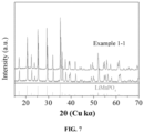
- 238000002441 X-ray diffraction Methods 0.000 description 3
- FMRLDPWIRHBCCC-UHFFFAOYSA-L Zinc carbonate Chemical compound [Zn+2].[O-]C([O-])=O FMRLDPWIRHBCCC-UHFFFAOYSA-L 0.000 description 3
- 229910000147 aluminium phosphate Inorganic materials 0.000 description 3
- 230000008901 benefit Effects 0.000 description 3
- KRKNYBCHXYNGOX-UHFFFAOYSA-N citric acid Chemical compound OC(=O)CC(O)(C(O)=O)CC(O)=O KRKNYBCHXYNGOX-UHFFFAOYSA-N 0.000 description 3
- 238000009826 distribution Methods 0.000 description 3
- 238000004146 energy storage Methods 0.000 description 3
- JBTWLSYIZRCDFO-UHFFFAOYSA-N ethyl methyl carbonate Chemical compound CCOC(=O)OC JBTWLSYIZRCDFO-UHFFFAOYSA-N 0.000 description 3
- 238000005227 gel permeation chromatography Methods 0.000 description 3
- XLYOFNOQVPJJNP-ZSJDYOACSA-N heavy water Substances [2H]O[2H] XLYOFNOQVPJJNP-ZSJDYOACSA-N 0.000 description 3
- 238000009616 inductively coupled plasma Methods 0.000 description 3
- 150000002500 ions Chemical class 0.000 description 3
- HDJUVFZHZGPHCQ-UHFFFAOYSA-L manganese(2+);oxalate;dihydrate Chemical compound O.O.[Mn+2].[O-]C(=O)C([O-])=O HDJUVFZHZGPHCQ-UHFFFAOYSA-L 0.000 description 3
- SFMJNHNUOVADRW-UHFFFAOYSA-N n-[5-[9-[4-(methanesulfonamido)phenyl]-2-oxobenzo[h][1,6]naphthyridin-1-yl]-2-methylphenyl]prop-2-enamide Chemical compound C1=C(NC(=O)C=C)C(C)=CC=C1N1C(=O)C=CC2=C1C1=CC(C=3C=CC(NS(C)(=O)=O)=CC=3)=CC=C1N=C2 SFMJNHNUOVADRW-UHFFFAOYSA-N 0.000 description 3
- 229910000008 nickel(II) carbonate Inorganic materials 0.000 description 3
- 229920003023 plastic Polymers 0.000 description 3
- 239000004033 plastic Substances 0.000 description 3
- 229920002451 polyvinyl alcohol Polymers 0.000 description 3
- 239000000047 product Substances 0.000 description 3
- 230000001737 promoting effect Effects 0.000 description 3
- 239000007784 solid electrolyte Substances 0.000 description 3
- 238000004448 titration Methods 0.000 description 3
- 229910001868 water Inorganic materials 0.000 description 3
- 235000004416 zinc carbonate Nutrition 0.000 description 3
- ZZXUZKXVROWEIF-UHFFFAOYSA-N 1,2-butylene carbonate Chemical compound CCC1COC(=O)O1 ZZXUZKXVROWEIF-UHFFFAOYSA-N 0.000 description 2
- YIWGJFPJRAEKMK-UHFFFAOYSA-N 1-(2H-benzotriazol-5-yl)-3-methyl-8-[2-[[3-(trifluoromethoxy)phenyl]methylamino]pyrimidine-5-carbonyl]-1,3,8-triazaspiro[4.5]decane-2,4-dione Chemical compound CN1C(=O)N(c2ccc3n[nH]nc3c2)C2(CCN(CC2)C(=O)c2cnc(NCc3cccc(OC(F)(F)F)c3)nc2)C1=O YIWGJFPJRAEKMK-UHFFFAOYSA-N 0.000 description 2
- HMUNWXXNJPVALC-UHFFFAOYSA-N 1-[4-[2-(2,3-dihydro-1H-inden-2-ylamino)pyrimidin-5-yl]piperazin-1-yl]-2-(2,4,6,7-tetrahydrotriazolo[4,5-c]pyridin-5-yl)ethanone Chemical compound C1C(CC2=CC=CC=C12)NC1=NC=C(C=N1)N1CCN(CC1)C(CN1CC2=C(CC1)NN=N2)=O HMUNWXXNJPVALC-UHFFFAOYSA-N 0.000 description 2
- HNAGHMKIPMKKBB-UHFFFAOYSA-N 1-benzylpyrrolidine-3-carboxamide Chemical compound C1C(C(=O)N)CCN1CC1=CC=CC=C1 HNAGHMKIPMKKBB-UHFFFAOYSA-N 0.000 description 2
- LDXJRKWFNNFDSA-UHFFFAOYSA-N 2-(2,4,6,7-tetrahydrotriazolo[4,5-c]pyridin-5-yl)-1-[4-[2-[[3-(trifluoromethoxy)phenyl]methylamino]pyrimidin-5-yl]piperazin-1-yl]ethanone Chemical compound C1CN(CC2=NNN=C21)CC(=O)N3CCN(CC3)C4=CN=C(N=C4)NCC5=CC(=CC=C5)OC(F)(F)F LDXJRKWFNNFDSA-UHFFFAOYSA-N 0.000 description 2
- YEJRWHAVMIAJKC-UHFFFAOYSA-N 4-Butyrolactone Chemical compound O=C1CCCO1 YEJRWHAVMIAJKC-UHFFFAOYSA-N 0.000 description 2
- SBLRHMKNNHXPHG-UHFFFAOYSA-N 4-fluoro-1,3-dioxolan-2-one Chemical compound FC1COC(=O)O1 SBLRHMKNNHXPHG-UHFFFAOYSA-N 0.000 description 2
- 239000004925 Acrylic resin Substances 0.000 description 2
- 229910001316 Ag alloy Inorganic materials 0.000 description 2
- VEXZGXHMUGYJMC-UHFFFAOYSA-N Hydrochloric acid Chemical compound Cl VEXZGXHMUGYJMC-UHFFFAOYSA-N 0.000 description 2
- 238000004566 IR spectroscopy Methods 0.000 description 2
- JGFBQFKZKSSODQ-UHFFFAOYSA-N Isothiocyanatocyclopropane Chemical compound S=C=NC1CC1 JGFBQFKZKSSODQ-UHFFFAOYSA-N 0.000 description 2
- RJUFJBKOKNCXHH-UHFFFAOYSA-N Methyl propionate Chemical compound CCC(=O)OC RJUFJBKOKNCXHH-UHFFFAOYSA-N 0.000 description 2
- MKYBYDHXWVHEJW-UHFFFAOYSA-N N-[1-oxo-1-(2,4,6,7-tetrahydrotriazolo[4,5-c]pyridin-5-yl)propan-2-yl]-2-[[3-(trifluoromethoxy)phenyl]methylamino]pyrimidine-5-carboxamide Chemical compound O=C(C(C)NC(=O)C=1C=NC(=NC=1)NCC1=CC(=CC=C1)OC(F)(F)F)N1CC2=C(CC1)NN=N2 MKYBYDHXWVHEJW-UHFFFAOYSA-N 0.000 description 2
- AFCARXCZXQIEQB-UHFFFAOYSA-N N-[3-oxo-3-(2,4,6,7-tetrahydrotriazolo[4,5-c]pyridin-5-yl)propyl]-2-[[3-(trifluoromethoxy)phenyl]methylamino]pyrimidine-5-carboxamide Chemical compound O=C(CCNC(=O)C=1C=NC(=NC=1)NCC1=CC(=CC=C1)OC(F)(F)F)N1CC2=C(CC1)NN=N2 AFCARXCZXQIEQB-UHFFFAOYSA-N 0.000 description 2
- VCUFZILGIRCDQQ-KRWDZBQOSA-N N-[[(5S)-2-oxo-3-(2-oxo-3H-1,3-benzoxazol-6-yl)-1,3-oxazolidin-5-yl]methyl]-2-[[3-(trifluoromethoxy)phenyl]methylamino]pyrimidine-5-carboxamide Chemical compound O=C1O[C@H](CN1C1=CC2=C(NC(O2)=O)C=C1)CNC(=O)C=1C=NC(=NC=1)NCC1=CC(=CC=C1)OC(F)(F)F VCUFZILGIRCDQQ-KRWDZBQOSA-N 0.000 description 2
- 238000005481 NMR spectroscopy Methods 0.000 description 2
- 229910000990 Ni alloy Inorganic materials 0.000 description 2
- 229920002845 Poly(methacrylic acid) Polymers 0.000 description 2
- 239000004793 Polystyrene Substances 0.000 description 2
- XBDQKXXYIPTUBI-UHFFFAOYSA-M Propionate Chemical compound CCC([O-])=O XBDQKXXYIPTUBI-UHFFFAOYSA-M 0.000 description 2
- VYPSYNLAJGMNEJ-UHFFFAOYSA-N Silicium dioxide Chemical compound O=[Si]=O VYPSYNLAJGMNEJ-UHFFFAOYSA-N 0.000 description 2
- BQCADISMDOOEFD-UHFFFAOYSA-N Silver Chemical compound [Ag] BQCADISMDOOEFD-UHFFFAOYSA-N 0.000 description 2
- 229910001069 Ti alloy Inorganic materials 0.000 description 2
- JAWMENYCRQKKJY-UHFFFAOYSA-N [3-(2,4,6,7-tetrahydrotriazolo[4,5-c]pyridin-5-ylmethyl)-1-oxa-2,8-diazaspiro[4.5]dec-2-en-8-yl]-[2-[[3-(trifluoromethoxy)phenyl]methylamino]pyrimidin-5-yl]methanone Chemical compound N1N=NC=2CN(CCC=21)CC1=NOC2(C1)CCN(CC2)C(=O)C=1C=NC(=NC=1)NCC1=CC(=CC=C1)OC(F)(F)F JAWMENYCRQKKJY-UHFFFAOYSA-N 0.000 description 2
- KXKVLQRXCPHEJC-UHFFFAOYSA-N acetic acid trimethyl ester Natural products COC(C)=O KXKVLQRXCPHEJC-UHFFFAOYSA-N 0.000 description 2
- DPXJVFZANSGRMM-UHFFFAOYSA-N acetic acid;2,3,4,5,6-pentahydroxyhexanal;sodium Chemical compound [Na].CC(O)=O.OCC(O)C(O)C(O)C(O)C=O DPXJVFZANSGRMM-UHFFFAOYSA-N 0.000 description 2
- 239000000956 alloy Substances 0.000 description 2
- 229910021383 artificial graphite Inorganic materials 0.000 description 2
- 230000015572 biosynthetic process Effects 0.000 description 2
- OBNCKNCVKJNDBV-UHFFFAOYSA-N butanoic acid ethyl ester Natural products CCCC(=O)OCC OBNCKNCVKJNDBV-UHFFFAOYSA-N 0.000 description 2
- PWLNAUNEAKQYLH-UHFFFAOYSA-N butyric acid octyl ester Natural products CCCCCCCCOC(=O)CCC PWLNAUNEAKQYLH-UHFFFAOYSA-N 0.000 description 2
- 239000006227 byproduct Substances 0.000 description 2
- 239000006229 carbon black Substances 0.000 description 2
- 239000002134 carbon nanofiber Substances 0.000 description 2
- 229910021393 carbon nanotube Inorganic materials 0.000 description 2
- 239000002041 carbon nanotube Substances 0.000 description 2
- 229910000361 cobalt sulfate Inorganic materials 0.000 description 2
- 229940044175 cobalt sulfate Drugs 0.000 description 2
- 229920001577 copolymer Polymers 0.000 description 2
- 239000011889 copper foil Substances 0.000 description 2
- MNNHAPBLZZVQHP-UHFFFAOYSA-N diammonium hydrogen phosphate Chemical compound [NH4+].[NH4+].OP([O-])([O-])=O MNNHAPBLZZVQHP-UHFFFAOYSA-N 0.000 description 2
- IJKVHSBPTUYDLN-UHFFFAOYSA-N dihydroxy(oxo)silane Chemical compound O[Si](O)=O IJKVHSBPTUYDLN-UHFFFAOYSA-N 0.000 description 2
- HNCXPJFPCAYUGJ-UHFFFAOYSA-N dilithium bis(trifluoromethylsulfonyl)azanide Chemical compound [Li+].[Li+].FC(F)(F)S(=O)(=O)[N-]S(=O)(=O)C(F)(F)F.FC(F)(F)S(=O)(=O)[N-]S(=O)(=O)C(F)(F)F HNCXPJFPCAYUGJ-UHFFFAOYSA-N 0.000 description 2
- VUPKGFBOKBGHFZ-UHFFFAOYSA-N dipropyl carbonate Chemical compound CCCOC(=O)OCCC VUPKGFBOKBGHFZ-UHFFFAOYSA-N 0.000 description 2
- 239000006185 dispersion Substances 0.000 description 2
- 238000005430 electron energy loss spectroscopy Methods 0.000 description 2
- 238000005516 engineering process Methods 0.000 description 2
- 125000002573 ethenylidene group Chemical group [*]=C=C([H])[H] 0.000 description 2
- CYEDOLFRAIXARV-UHFFFAOYSA-N ethyl propyl carbonate Chemical compound CCCOC(=O)OCC CYEDOLFRAIXARV-UHFFFAOYSA-N 0.000 description 2
- 230000002349 favourable effect Effects 0.000 description 2
- 239000007789 gas Substances 0.000 description 2
- 238000005469 granulation Methods 0.000 description 2
- 230000003179 granulation Effects 0.000 description 2
- 229910021389 graphene Inorganic materials 0.000 description 2
- 229910002804 graphite Inorganic materials 0.000 description 2
- 239000010439 graphite Substances 0.000 description 2
- 230000005484 gravity Effects 0.000 description 2
- 229910021385 hard carbon Inorganic materials 0.000 description 2
- 230000002401 inhibitory effect Effects 0.000 description 2
- 230000037427 ion transport Effects 0.000 description 2
- 239000003273 ketjen black Substances 0.000 description 2
- OMLOBRLMBKBLOH-UHFFFAOYSA-K lithium manganese(2+) phosphate Chemical group [Mn+2].[Li+].P(=O)([O-])([O-])[O-].[Mn+2] OMLOBRLMBKBLOH-UHFFFAOYSA-K 0.000 description 2
- 229910001496 lithium tetrafluoroborate Inorganic materials 0.000 description 2
- NUJOXMJBOLGQSY-UHFFFAOYSA-N manganese dioxide Chemical compound O=[Mn]=O NUJOXMJBOLGQSY-UHFFFAOYSA-N 0.000 description 2
- 238000000691 measurement method Methods 0.000 description 2
- 229940017219 methyl propionate Drugs 0.000 description 2
- KKQAVHGECIBFRQ-UHFFFAOYSA-N methyl propyl carbonate Chemical compound CCCOC(=O)OC KKQAVHGECIBFRQ-UHFFFAOYSA-N 0.000 description 2
- 150000002772 monosaccharides Chemical class 0.000 description 2
- YKYONYBAUNKHLG-UHFFFAOYSA-N n-Propyl acetate Natural products CCCOC(C)=O YKYONYBAUNKHLG-UHFFFAOYSA-N 0.000 description 2
- UUIQMZJEGPQKFD-UHFFFAOYSA-N n-butyric acid methyl ester Natural products CCCC(=O)OC UUIQMZJEGPQKFD-UHFFFAOYSA-N 0.000 description 2
- ZULUUIKRFGGGTL-UHFFFAOYSA-L nickel(ii) carbonate Chemical compound [Ni+2].[O-]C([O-])=O ZULUUIKRFGGGTL-UHFFFAOYSA-L 0.000 description 2
- 239000003960 organic solvent Substances 0.000 description 2
- DCKVFVYPWDKYDN-UHFFFAOYSA-L oxygen(2-);titanium(4+);sulfate Chemical compound [O-2].[Ti+4].[O-]S([O-])(=O)=O DCKVFVYPWDKYDN-UHFFFAOYSA-L 0.000 description 2
- 150000003013 phosphoric acid derivatives Chemical class 0.000 description 2
- 229920002401 polyacrylamide Polymers 0.000 description 2
- 239000004584 polyacrylic acid Substances 0.000 description 2
- 229920002961 polybutylene succinate Polymers 0.000 description 2
- 239000004631 polybutylene succinate Substances 0.000 description 2
- 239000002861 polymer material Substances 0.000 description 2
- 229920001343 polytetrafluoroethylene Polymers 0.000 description 2
- 239000004810 polytetrafluoroethylene Substances 0.000 description 2
- 238000003825 pressing Methods 0.000 description 2
- 229940090181 propyl acetate Drugs 0.000 description 2
- RUOJZAUFBMNUDX-UHFFFAOYSA-N propylene carbonate Chemical compound CC1COC(=O)O1 RUOJZAUFBMNUDX-UHFFFAOYSA-N 0.000 description 2
- 230000001681 protective effect Effects 0.000 description 2
- 238000007790 scraping Methods 0.000 description 2
- 238000007873 sieving Methods 0.000 description 2
- 239000002210 silicon-based material Substances 0.000 description 2
- 239000004332 silver Substances 0.000 description 2
- 235000019812 sodium carboxymethyl cellulose Nutrition 0.000 description 2
- 229920001027 sodium carboxymethylcellulose Polymers 0.000 description 2
- 238000001228 spectrum Methods 0.000 description 2
- 229920003048 styrene butadiene rubber Polymers 0.000 description 2
- HXJUTPCZVOIRIF-UHFFFAOYSA-N sulfolane Chemical compound O=S1(=O)CCCC1 HXJUTPCZVOIRIF-UHFFFAOYSA-N 0.000 description 2
- HHVIBTZHLRERCL-UHFFFAOYSA-N sulfonyldimethane Chemical compound CS(C)(=O)=O HHVIBTZHLRERCL-UHFFFAOYSA-N 0.000 description 2
- 229920001897 terpolymer Polymers 0.000 description 2
- 239000002562 thickening agent Substances 0.000 description 2
- 239000011366 tin-based material Substances 0.000 description 2
- 229910000348 titanium sulfate Inorganic materials 0.000 description 2
- 230000007704 transition Effects 0.000 description 2
- 229910001428 transition metal ion Inorganic materials 0.000 description 2
- NQPDZGIKBAWPEJ-UHFFFAOYSA-N valeric acid Chemical compound CCCCC(O)=O NQPDZGIKBAWPEJ-UHFFFAOYSA-N 0.000 description 2
- 238000004804 winding Methods 0.000 description 2
- MBDUIEKYVPVZJH-UHFFFAOYSA-N 1-ethylsulfonylethane Chemical compound CCS(=O)(=O)CC MBDUIEKYVPVZJH-UHFFFAOYSA-N 0.000 description 1
- YBJCDTIWNDBNTM-UHFFFAOYSA-N 1-methylsulfonylethane Chemical compound CCS(C)(=O)=O YBJCDTIWNDBNTM-UHFFFAOYSA-N 0.000 description 1
- UHOPWFKONJYLCF-UHFFFAOYSA-N 2-(2-sulfanylethyl)isoindole-1,3-dione Chemical compound C1=CC=C2C(=O)N(CCS)C(=O)C2=C1 UHOPWFKONJYLCF-UHFFFAOYSA-N 0.000 description 1
- 229920000178 Acrylic resin Polymers 0.000 description 1
- 229910000838 Al alloy Inorganic materials 0.000 description 1
- QGZKDVFQNNGYKY-UHFFFAOYSA-O Ammonium Chemical compound [NH4+] QGZKDVFQNNGYKY-UHFFFAOYSA-O 0.000 description 1
- 239000004254 Ammonium phosphate Substances 0.000 description 1
- 241000252073 Anguilliformes Species 0.000 description 1
- BVKZGUZCCUSVTD-UHFFFAOYSA-L Carbonate Chemical compound [O-]C([O-])=O BVKZGUZCCUSVTD-UHFFFAOYSA-L 0.000 description 1
- 229910000881 Cu alloy Inorganic materials 0.000 description 1
- WQZGKKKJIJFFOK-GASJEMHNSA-N Glucose Natural products OC[C@H]1OC(O)[C@H](O)[C@@H](O)[C@@H]1O WQZGKKKJIJFFOK-GASJEMHNSA-N 0.000 description 1
- 229910003641 H2SiO3 Inorganic materials 0.000 description 1
- 229920000869 Homopolysaccharide Polymers 0.000 description 1
- 230000005536 Jahn Teller effect Effects 0.000 description 1
- 239000002841 Lewis acid Substances 0.000 description 1
- 229910012265 LiPO2F2 Inorganic materials 0.000 description 1
- 229910000572 Lithium Nickel Cobalt Manganese Oxide (NCM) Inorganic materials 0.000 description 1
- 229910018663 Mn O Inorganic materials 0.000 description 1
- 229910003176 Mn-O Inorganic materials 0.000 description 1
- NEAPKZHDYMQZCB-UHFFFAOYSA-N N-[2-[4-[2-(2,3-dihydro-1H-inden-2-ylamino)pyrimidin-5-yl]piperazin-1-yl]ethyl]-2-oxo-3H-1,3-benzoxazole-6-carboxamide Chemical compound C1CN(CCN1CCNC(=O)C2=CC3=C(C=C2)NC(=O)O3)C4=CN=C(N=C4)NC5CC6=CC=CC=C6C5 NEAPKZHDYMQZCB-UHFFFAOYSA-N 0.000 description 1
- AUBNQVSSTJZVMY-UHFFFAOYSA-M P(=O)([O-])(O)O.C(C(=O)O)(=O)F.C(C(=O)O)(=O)F.C(C(=O)O)(=O)F.C(C(=O)O)(=O)F.[Li+] Chemical compound P(=O)([O-])(O)O.C(C(=O)O)(=O)F.C(C(=O)O)(=O)F.C(C(=O)O)(=O)F.C(C(=O)O)(=O)F.[Li+] AUBNQVSSTJZVMY-UHFFFAOYSA-M 0.000 description 1
- 101150096185 PAAS gene Proteins 0.000 description 1
- 239000002202 Polyethylene glycol Substances 0.000 description 1
- 229910000676 Si alloy Inorganic materials 0.000 description 1
- XUIMIQQOPSSXEZ-UHFFFAOYSA-N Silicon Chemical compound [Si] XUIMIQQOPSSXEZ-UHFFFAOYSA-N 0.000 description 1
- 229910001128 Sn alloy Inorganic materials 0.000 description 1
- 229910000831 Steel Inorganic materials 0.000 description 1
- 238000003917 TEM image Methods 0.000 description 1
- 229920006172 Tetrafluoroethylene propylene Polymers 0.000 description 1
- 229910011006 Ti(SO4)2 Inorganic materials 0.000 description 1
- ATJFFYVFTNAWJD-UHFFFAOYSA-N Tin Chemical compound [Sn] ATJFFYVFTNAWJD-UHFFFAOYSA-N 0.000 description 1
- VIEVWNYBKMKQIH-UHFFFAOYSA-N [Co]=O.[Mn].[Li] Chemical compound [Co]=O.[Mn].[Li] VIEVWNYBKMKQIH-UHFFFAOYSA-N 0.000 description 1
- QTHKJEYUQSLYTH-UHFFFAOYSA-N [Co]=O.[Ni].[Li] Chemical compound [Co]=O.[Ni].[Li] QTHKJEYUQSLYTH-UHFFFAOYSA-N 0.000 description 1
- SYRDSFGUUQPYOB-UHFFFAOYSA-N [Li+].[Li+].[Li+].[O-]B([O-])[O-].FC(=O)C(F)=O Chemical compound [Li+].[Li+].[Li+].[O-]B([O-])[O-].FC(=O)C(F)=O SYRDSFGUUQPYOB-UHFFFAOYSA-N 0.000 description 1
- UMVBXBACMIOFDO-UHFFFAOYSA-N [N].[Si] Chemical compound [N].[Si] UMVBXBACMIOFDO-UHFFFAOYSA-N 0.000 description 1
- FBDMTTNVIIVBKI-UHFFFAOYSA-N [O-2].[Mn+2].[Co+2].[Ni+2].[Li+] Chemical compound [O-2].[Mn+2].[Co+2].[Ni+2].[Li+] FBDMTTNVIIVBKI-UHFFFAOYSA-N 0.000 description 1
- 238000010521 absorption reaction Methods 0.000 description 1
- 238000002479 acid--base titration Methods 0.000 description 1
- 150000001252 acrylic acid derivatives Chemical class 0.000 description 1
- 230000003213 activating effect Effects 0.000 description 1
- 239000011149 active material Substances 0.000 description 1
- 230000004075 alteration Effects 0.000 description 1
- NDPGDHBNXZOBJS-UHFFFAOYSA-N aluminum lithium cobalt(2+) nickel(2+) oxygen(2-) Chemical compound [Li+].[O--].[O--].[O--].[O--].[Al+3].[Co++].[Ni++] NDPGDHBNXZOBJS-UHFFFAOYSA-N 0.000 description 1
- 229910000148 ammonium phosphate Inorganic materials 0.000 description 1
- 235000019289 ammonium phosphates Nutrition 0.000 description 1
- 239000012300 argon atmosphere Substances 0.000 description 1
- 230000000712 assembly Effects 0.000 description 1
- 238000000429 assembly Methods 0.000 description 1
- WQZGKKKJIJFFOK-VFUOTHLCSA-N beta-D-glucose Chemical compound OC[C@H]1O[C@@H](O)[C@H](O)[C@@H](O)[C@@H]1O WQZGKKKJIJFFOK-VFUOTHLCSA-N 0.000 description 1
- 230000005540 biological transmission Effects 0.000 description 1
- 239000003575 carbonaceous material Substances 0.000 description 1
- 150000004649 carbonic acid derivatives Chemical class 0.000 description 1
- ONIOAEVPMYCHKX-UHFFFAOYSA-N carbonic acid;zinc Chemical compound [Zn].OC(O)=O ONIOAEVPMYCHKX-UHFFFAOYSA-N 0.000 description 1
- 239000003054 catalyst Substances 0.000 description 1
- 239000003153 chemical reaction reagent Substances 0.000 description 1
- 239000000470 constituent Substances 0.000 description 1
- 238000007796 conventional method Methods 0.000 description 1
- 230000001186 cumulative effect Effects 0.000 description 1
- 238000000354 decomposition reaction Methods 0.000 description 1
- 238000004807 desolvation Methods 0.000 description 1
- 229910000388 diammonium phosphate Inorganic materials 0.000 description 1
- 235000019838 diammonium phosphate Nutrition 0.000 description 1
- 238000000113 differential scanning calorimetry Methods 0.000 description 1
- 238000009792 diffusion process Methods 0.000 description 1
- 238000007599 discharging Methods 0.000 description 1
- 238000000295 emission spectrum Methods 0.000 description 1
- 238000005538 encapsulation Methods 0.000 description 1
- RTZKZFJDLAIYFH-UHFFFAOYSA-N ether Substances CCOCC RTZKZFJDLAIYFH-UHFFFAOYSA-N 0.000 description 1
- 239000011790 ferrous sulphate Substances 0.000 description 1
- 235000003891 ferrous sulphate Nutrition 0.000 description 1
- ZZUFCTLCJUWOSV-UHFFFAOYSA-N furosemide Chemical compound C1=C(Cl)C(S(=O)(=O)N)=CC(C(O)=O)=C1NCC1=CC=CO1 ZZUFCTLCJUWOSV-UHFFFAOYSA-N 0.000 description 1
- 239000000499 gel Substances 0.000 description 1
- 239000003365 glass fiber Substances 0.000 description 1
- 239000008103 glucose Substances 0.000 description 1
- 238000000227 grinding Methods 0.000 description 1
- 238000010438 heat treatment Methods 0.000 description 1
- CPSYWNLKRDURMG-UHFFFAOYSA-L hydron;manganese(2+);phosphate Chemical compound [Mn+2].OP([O-])([O-])=O CPSYWNLKRDURMG-UHFFFAOYSA-L 0.000 description 1
- 230000005764 inhibitory process Effects 0.000 description 1
- 230000016507 interphase Effects 0.000 description 1
- 235000014413 iron hydroxide Nutrition 0.000 description 1
- BAUYGSIQEAFULO-UHFFFAOYSA-L iron(2+) sulfate (anhydrous) Chemical compound [Fe+2].[O-]S([O-])(=O)=O BAUYGSIQEAFULO-UHFFFAOYSA-L 0.000 description 1
- 229910000359 iron(II) sulfate Inorganic materials 0.000 description 1
- NCNCGGDMXMBVIA-UHFFFAOYSA-L iron(ii) hydroxide Chemical compound [OH-].[OH-].[Fe+2] NCNCGGDMXMBVIA-UHFFFAOYSA-L 0.000 description 1
- 230000002427 irreversible effect Effects 0.000 description 1
- 238000002955 isolation Methods 0.000 description 1
- 239000002346 layers by function Substances 0.000 description 1
- 150000007517 lewis acids Chemical class 0.000 description 1
- 239000011244 liquid electrolyte Substances 0.000 description 1
- 229910000625 lithium cobalt oxide Inorganic materials 0.000 description 1
- DEUISMFZZMAAOJ-UHFFFAOYSA-N lithium dihydrogen borate oxalic acid Chemical compound B([O-])(O)O.C(C(=O)O)(=O)O.C(C(=O)O)(=O)O.[Li+] DEUISMFZZMAAOJ-UHFFFAOYSA-N 0.000 description 1
- 229910001540 lithium hexafluoroarsenate(V) Inorganic materials 0.000 description 1
- 229910002102 lithium manganese oxide Inorganic materials 0.000 description 1
- FRMOHNDAXZZWQI-UHFFFAOYSA-N lithium manganese(2+) nickel(2+) oxygen(2-) Chemical compound [O-2].[Mn+2].[Ni+2].[Li+] FRMOHNDAXZZWQI-UHFFFAOYSA-N 0.000 description 1
- MHCFAGZWMAWTNR-UHFFFAOYSA-M lithium perchlorate Chemical compound [Li+].[O-]Cl(=O)(=O)=O MHCFAGZWMAWTNR-UHFFFAOYSA-M 0.000 description 1
- 229910001386 lithium phosphate Inorganic materials 0.000 description 1
- 229910021437 lithium-transition metal oxide Inorganic materials 0.000 description 1
- IGILRSKEFZLPKG-UHFFFAOYSA-M lithium;difluorophosphinate Chemical compound [Li+].[O-]P(F)(F)=O IGILRSKEFZLPKG-UHFFFAOYSA-M 0.000 description 1
- SNKMVYBWZDHJHE-UHFFFAOYSA-M lithium;dihydrogen phosphate Chemical compound [Li+].OP(O)([O-])=O SNKMVYBWZDHJHE-UHFFFAOYSA-M 0.000 description 1
- BFZPBUKRYWOWDV-UHFFFAOYSA-N lithium;oxido(oxo)cobalt Chemical compound [Li+].[O-][Co]=O BFZPBUKRYWOWDV-UHFFFAOYSA-N 0.000 description 1
- VLXXBCXTUVRROQ-UHFFFAOYSA-N lithium;oxido-oxo-(oxomanganiooxy)manganese Chemical compound [Li+].[O-][Mn](=O)O[Mn]=O VLXXBCXTUVRROQ-UHFFFAOYSA-N 0.000 description 1
- URIIGZKXFBNRAU-UHFFFAOYSA-N lithium;oxonickel Chemical compound [Li].[Ni]=O URIIGZKXFBNRAU-UHFFFAOYSA-N 0.000 description 1
- MCVFFRWZNYZUIJ-UHFFFAOYSA-M lithium;trifluoromethanesulfonate Chemical compound [Li+].[O-]S(=O)(=O)C(F)(F)F MCVFFRWZNYZUIJ-UHFFFAOYSA-M 0.000 description 1
- 229920002521 macromolecule Polymers 0.000 description 1
- WPBNNNQJVZRUHP-UHFFFAOYSA-L manganese(2+);methyl n-[[2-(methoxycarbonylcarbamothioylamino)phenyl]carbamothioyl]carbamate;n-[2-(sulfidocarbothioylamino)ethyl]carbamodithioate Chemical compound [Mn+2].[S-]C(=S)NCCNC([S-])=S.COC(=O)NC(=S)NC1=CC=CC=C1NC(=S)NC(=O)OC WPBNNNQJVZRUHP-UHFFFAOYSA-L 0.000 description 1
- 238000005259 measurement Methods 0.000 description 1
- 150000002739 metals Chemical class 0.000 description 1
- 238000003801 milling Methods 0.000 description 1
- 229910021382 natural graphite Inorganic materials 0.000 description 1
- 239000004745 nonwoven fabric Substances 0.000 description 1
- 235000005985 organic acids Nutrition 0.000 description 1
- 235000006408 oxalic acid Nutrition 0.000 description 1
- 238000003921 particle size analysis Methods 0.000 description 1
- 235000011007 phosphoric acid Nutrition 0.000 description 1
- 229920001223 polyethylene glycol Polymers 0.000 description 1
- 239000011148 porous material Substances 0.000 description 1
- 238000001556 precipitation Methods 0.000 description 1
- 239000011164 primary particle Substances 0.000 description 1
- 239000011241 protective layer Substances 0.000 description 1
- 230000009257 reactivity Effects 0.000 description 1
- 230000003252 repetitive effect Effects 0.000 description 1
- 239000011347 resin Substances 0.000 description 1
- 229920005989 resin Polymers 0.000 description 1
- 230000000284 resting effect Effects 0.000 description 1
- 239000004576 sand Substances 0.000 description 1
- 238000007493 shaping process Methods 0.000 description 1
- 239000010703 silicon Substances 0.000 description 1
- 229910052814 silicon oxide Inorganic materials 0.000 description 1
- 239000002153 silicon-carbon composite material Substances 0.000 description 1
- 239000002356 single layer Substances 0.000 description 1
- 159000000000 sodium salts Chemical class 0.000 description 1
- 229910021384 soft carbon Inorganic materials 0.000 description 1
- 239000010959 steel Substances 0.000 description 1
- 238000012916 structural analysis Methods 0.000 description 1
- 239000001117 sulphuric acid Substances 0.000 description 1
- 235000011149 sulphuric acid Nutrition 0.000 description 1
- 239000013589 supplement Substances 0.000 description 1
- 230000002195 synergetic effect Effects 0.000 description 1
- 238000010998 test method Methods 0.000 description 1
- XOLBLPGZBRYERU-UHFFFAOYSA-N tin dioxide Chemical compound O=[Sn]=O XOLBLPGZBRYERU-UHFFFAOYSA-N 0.000 description 1
- 229910001887 tin oxide Inorganic materials 0.000 description 1
- HDUMBHAAKGUHAR-UHFFFAOYSA-J titanium(4+);disulfate Chemical compound [Ti+4].[O-]S([O-])(=O)=O.[O-]S([O-])(=O)=O HDUMBHAAKGUHAR-UHFFFAOYSA-J 0.000 description 1
- 229910052723 transition metal Inorganic materials 0.000 description 1
- 150000003624 transition metals Chemical class 0.000 description 1
- TWQULNDIKKJZPH-UHFFFAOYSA-K trilithium;phosphate Chemical compound [Li+].[Li+].[Li+].[O-]P([O-])([O-])=O TWQULNDIKKJZPH-UHFFFAOYSA-K 0.000 description 1
- 238000009827 uniform distribution Methods 0.000 description 1
Images


Classifications
-
- H—ELECTRICITY
- H01—ELECTRIC ELEMENTS
- H01M—PROCESSES OR MEANS, e.g. BATTERIES, FOR THE DIRECT CONVERSION OF CHEMICAL ENERGY INTO ELECTRICAL ENERGY
- H01M4/00—Electrodes
- H01M4/02—Electrodes composed of, or comprising, active material
- H01M4/36—Selection of substances as active materials, active masses, active liquids
- H01M4/362—Composites
- H01M4/366—Composites as layered products
-
- H—ELECTRICITY
- H01—ELECTRIC ELEMENTS
- H01M—PROCESSES OR MEANS, e.g. BATTERIES, FOR THE DIRECT CONVERSION OF CHEMICAL ENERGY INTO ELECTRICAL ENERGY
- H01M4/00—Electrodes
- H01M4/02—Electrodes composed of, or comprising, active material
- H01M4/36—Selection of substances as active materials, active masses, active liquids
-
- H—ELECTRICITY
- H01—ELECTRIC ELEMENTS
- H01M—PROCESSES OR MEANS, e.g. BATTERIES, FOR THE DIRECT CONVERSION OF CHEMICAL ENERGY INTO ELECTRICAL ENERGY
- H01M10/00—Secondary cells; Manufacture thereof
- H01M10/05—Accumulators with non-aqueous electrolyte
- H01M10/052—Li-accumulators
- H01M10/0525—Rocking-chair batteries, i.e. batteries with lithium insertion or intercalation in both electrodes; Lithium-ion batteries
-
- H—ELECTRICITY
- H01—ELECTRIC ELEMENTS
- H01M—PROCESSES OR MEANS, e.g. BATTERIES, FOR THE DIRECT CONVERSION OF CHEMICAL ENERGY INTO ELECTRICAL ENERGY
- H01M4/00—Electrodes
- H01M4/02—Electrodes composed of, or comprising, active material
- H01M4/04—Processes of manufacture in general
- H01M4/0471—Processes of manufacture in general involving thermal treatment, e.g. firing, sintering, backing particulate active material, thermal decomposition, pyrolysis
-
- H—ELECTRICITY
- H01—ELECTRIC ELEMENTS
- H01M—PROCESSES OR MEANS, e.g. BATTERIES, FOR THE DIRECT CONVERSION OF CHEMICAL ENERGY INTO ELECTRICAL ENERGY
- H01M4/00—Electrodes
- H01M4/02—Electrodes composed of, or comprising, active material
- H01M4/13—Electrodes for accumulators with non-aqueous electrolyte, e.g. for lithium-accumulators; Processes of manufacture thereof
- H01M4/136—Electrodes based on inorganic compounds other than oxides or hydroxides, e.g. sulfides, selenides, tellurides, halogenides or LiCoFy
-
- H—ELECTRICITY
- H01—ELECTRIC ELEMENTS
- H01M—PROCESSES OR MEANS, e.g. BATTERIES, FOR THE DIRECT CONVERSION OF CHEMICAL ENERGY INTO ELECTRICAL ENERGY
- H01M4/00—Electrodes
- H01M4/02—Electrodes composed of, or comprising, active material
- H01M4/13—Electrodes for accumulators with non-aqueous electrolyte, e.g. for lithium-accumulators; Processes of manufacture thereof
- H01M4/139—Processes of manufacture
- H01M4/1397—Processes of manufacture of electrodes based on inorganic compounds other than oxides or hydroxides, e.g. sulfides, selenides, tellurides, halogenides or LiCoFy
-
- H—ELECTRICITY
- H01—ELECTRIC ELEMENTS
- H01M—PROCESSES OR MEANS, e.g. BATTERIES, FOR THE DIRECT CONVERSION OF CHEMICAL ENERGY INTO ELECTRICAL ENERGY
- H01M4/00—Electrodes
- H01M4/02—Electrodes composed of, or comprising, active material
- H01M4/36—Selection of substances as active materials, active masses, active liquids
- H01M4/48—Selection of substances as active materials, active masses, active liquids of inorganic oxides or hydroxides
- H01M4/50—Selection of substances as active materials, active masses, active liquids of inorganic oxides or hydroxides of manganese
- H01M4/505—Selection of substances as active materials, active masses, active liquids of inorganic oxides or hydroxides of manganese of mixed oxides or hydroxides containing manganese for inserting or intercalating light metals, e.g. LiMn2O4 or LiMn2OxFy
-
- H—ELECTRICITY
- H01—ELECTRIC ELEMENTS
- H01M—PROCESSES OR MEANS, e.g. BATTERIES, FOR THE DIRECT CONVERSION OF CHEMICAL ENERGY INTO ELECTRICAL ENERGY
- H01M4/00—Electrodes
- H01M4/02—Electrodes composed of, or comprising, active material
- H01M4/36—Selection of substances as active materials, active masses, active liquids
- H01M4/48—Selection of substances as active materials, active masses, active liquids of inorganic oxides or hydroxides
- H01M4/52—Selection of substances as active materials, active masses, active liquids of inorganic oxides or hydroxides of nickel, cobalt or iron
- H01M4/525—Selection of substances as active materials, active masses, active liquids of inorganic oxides or hydroxides of nickel, cobalt or iron of mixed oxides or hydroxides containing iron, cobalt or nickel for inserting or intercalating light metals, e.g. LiNiO2, LiCoO2 or LiCoOxFy
-
- H—ELECTRICITY
- H01—ELECTRIC ELEMENTS
- H01M—PROCESSES OR MEANS, e.g. BATTERIES, FOR THE DIRECT CONVERSION OF CHEMICAL ENERGY INTO ELECTRICAL ENERGY
- H01M4/00—Electrodes
- H01M4/02—Electrodes composed of, or comprising, active material
- H01M4/36—Selection of substances as active materials, active masses, active liquids
- H01M4/58—Selection of substances as active materials, active masses, active liquids of inorganic compounds other than oxides or hydroxides, e.g. sulfides, selenides, tellurides, halogenides or LiCoFy; of polyanionic structures, e.g. phosphates, silicates or borates
- H01M4/5825—Oxygenated metallic salts or polyanionic structures, e.g. borates, phosphates, silicates, olivines
-
- H—ELECTRICITY
- H01—ELECTRIC ELEMENTS
- H01M—PROCESSES OR MEANS, e.g. BATTERIES, FOR THE DIRECT CONVERSION OF CHEMICAL ENERGY INTO ELECTRICAL ENERGY
- H01M4/00—Electrodes
- H01M4/02—Electrodes composed of, or comprising, active material
- H01M4/36—Selection of substances as active materials, active masses, active liquids
- H01M4/58—Selection of substances as active materials, active masses, active liquids of inorganic compounds other than oxides or hydroxides, e.g. sulfides, selenides, tellurides, halogenides or LiCoFy; of polyanionic structures, e.g. phosphates, silicates or borates
- H01M4/583—Carbonaceous material, e.g. graphite-intercalation compounds or CFx
-
- H—ELECTRICITY
- H01—ELECTRIC ELEMENTS
- H01M—PROCESSES OR MEANS, e.g. BATTERIES, FOR THE DIRECT CONVERSION OF CHEMICAL ENERGY INTO ELECTRICAL ENERGY
- H01M4/00—Electrodes
- H01M4/02—Electrodes composed of, or comprising, active material
- H01M4/36—Selection of substances as active materials, active masses, active liquids
- H01M4/60—Selection of substances as active materials, active masses, active liquids of organic compounds
- H01M4/602—Polymers
- H01M4/606—Polymers containing aromatic main chain polymers
- H01M4/608—Polymers containing aromatic main chain polymers containing heterocyclic rings
-
- H—ELECTRICITY
- H01—ELECTRIC ELEMENTS
- H01M—PROCESSES OR MEANS, e.g. BATTERIES, FOR THE DIRECT CONVERSION OF CHEMICAL ENERGY INTO ELECTRICAL ENERGY
- H01M4/00—Electrodes
- H01M4/02—Electrodes composed of, or comprising, active material
- H01M4/62—Selection of inactive substances as ingredients for active masses, e.g. binders, fillers
- H01M4/624—Electric conductive fillers
- H01M4/625—Carbon or graphite
-
- H—ELECTRICITY
- H01—ELECTRIC ELEMENTS
- H01M—PROCESSES OR MEANS, e.g. BATTERIES, FOR THE DIRECT CONVERSION OF CHEMICAL ENERGY INTO ELECTRICAL ENERGY
- H01M4/00—Electrodes
- H01M4/02—Electrodes composed of, or comprising, active material
- H01M2004/021—Physical characteristics, e.g. porosity, surface area
-
- H—ELECTRICITY
- H01—ELECTRIC ELEMENTS
- H01M—PROCESSES OR MEANS, e.g. BATTERIES, FOR THE DIRECT CONVERSION OF CHEMICAL ENERGY INTO ELECTRICAL ENERGY
- H01M4/00—Electrodes
- H01M4/02—Electrodes composed of, or comprising, active material
- H01M2004/026—Electrodes composed of, or comprising, active material characterised by the polarity
- H01M2004/028—Positive electrodes
-
- Y—GENERAL TAGGING OF NEW TECHNOLOGICAL DEVELOPMENTS; GENERAL TAGGING OF CROSS-SECTIONAL TECHNOLOGIES SPANNING OVER SEVERAL SECTIONS OF THE IPC; TECHNICAL SUBJECTS COVERED BY FORMER USPC CROSS-REFERENCE ART COLLECTIONS [XRACs] AND DIGESTS
- Y02—TECHNOLOGIES OR APPLICATIONS FOR MITIGATION OR ADAPTATION AGAINST CLIMATE CHANGE
- Y02E—REDUCTION OF GREENHOUSE GAS [GHG] EMISSIONS, RELATED TO ENERGY GENERATION, TRANSMISSION OR DISTRIBUTION
- Y02E60/00—Enabling technologies; Technologies with a potential or indirect contribution to GHG emissions mitigation
- Y02E60/10—Energy storage using batteries
Definitions
- the present application belongs to the technical field of batteries, in particular to a positive electrode active material, a method for the preparation thereof and a positive electrode plate, a secondary battery and an electrical device containing the same.
- lithium manganese phosphate has become one of the most popular positive electrode active materials due to its high capacity, good safety performance and abundant raw material sources.
- lithium manganese phosphate is prone to leaching-out of manganese ions during charging, resulting in rapid capacity decay. Therefore, it is necessary to provide a positive electrode active material with good overall performance.
- An object of the present application is to provide a positive electrode active material, a method for the preparation thereof, and a positive electrode plate, a secondary battery and an electrical device comprising the same, which material enables the secondary battery using the positive electrode active material to have a relatively high energy density, and good rate performance, cycling performance and safety performance.
- a first aspect of the present application provides a positive electrode active material having a core-shell structure, comprising a core and a shell cladding the core, wherein the core comprises Li 1+x Mn 1-y A y P 1-z R z O 4 , in which x is -0.100 to 0.100, y is 0.001 to 0.500, z is 0.001 to 0.100, A is selected from one or more of Zn, Al, Na, K, Mg, Mo, W, Ti, V, Zr, Fe, Ni, Co, Ga, Sn, Sb, Nb and Ge, optionally one or more of Fe, Ti, V, Ni, Co and Mg, and R is selected from one or more of B, Si, N and S; the shell comprises a first cladding layer cladding the core, a second cladding layer cladding the first cladding layer and a third cladding layer cladding the second cladding layer, wherein the first cladding layer comprises pyrophosphate MP 2 O 7 and phosphate
- the doping with specific element and surface cladding of lithium manganese phosphate can effectively inhibit leaching-out of manganese ions in the process of de-intercalation of lithium, and promote the migration of lithium ions, thereby improving the rate performance, cycling performance and safety performance of the secondary battery.
- the substituent attached to the sugar unit in the polymer comprises at least one of the group selected from the following functional groups: -OH, -COOH and the salts thereof, -R-OH, -SO 3 H and the salts thereof, -R-OH, -R-SO 3 H and the salts thereof, sulphate group, alkoxy group, and R represents alkylene, optionally, C1-C5 alkylene.
- the substituent attached to the sugar unit in the polymer comprises at least one of the group selected from the following functional groups: -OH, -COOH, -COOLi, -COONa, -COOK, -SO 3 H, -SO 3 Li, -SO 3 Na, -SO 3 K, -CH 2 -SO 3 H, -CH 2 -SO 3 Li, -CH 2 -SO 3 Na, -CH 2 -SO 3 K, methoxy, and ethoxy.
- the plant polysaccharide comprises one or more selected from pectin, carboxymethyl starch, hydroxypropyl starch, dextrin, cellulose ether, carboxymethyl chitosan, hydroxyethyl cellulose, carboxymethyl cellulose, carboxypropylmethyl cellulose, guar gum, sesbania gum, gum arabic, and the modified polymers thereof.
- the marine polysaccharide comprises one or more selected from lithium alginate, sodium alginate, potassium alginate, fucoidan, agar, carrageenan, carrageenin, xanthan gum, fenugreek gum and the modified polymers thereof.
- the polymer has a number average molecular weight of 10,000 to 200,000, optionally of 18,000 to 120,000.
- the number average molecular weight of the polymer within a suitable range allows the positive electrode active material to have both good dynamic performance and high-temperature stability.
- the substituent attached to the sugar unit is present in a mass percentage ⁇ in the polymer, with ⁇ being from 20% to 85%, optionally from 30% to 78%.
- ⁇ being from 20% to 85%, optionally from 30% to 78%.
- the mass percentage of the substituent attached to the sugar unit in the polymer within a suitable range allows a better cladding modification effect on the core.
- the first cladding layer has a cladding amount of greater than 0 and less than or equal to 7 wt%, optionally 4 wt% to 5.6 wt%, based on the weight of the core.
- the cladding amount of the first cladding layer is within the above range, the first cladding layer can effectively exert its function without affecting the dynamic performance of the secondary battery due to the too thick cladding layer.
- the second cladding layer has a cladding amount of greater than 0 and less than or equal to 6 wt%, optionally 3 wt% to 5 wt%, based on the weight of the core.
- the existence of the second cladding layer can avoid the direct contact between the positive electrode active material and the electrolytic solution, reduce the erosion of the positive electrode active material by the electrolytic solution, and improve the conductive ability of the positive electrode active material.
- the cladding amount of the second layer is within the above range, the specific capacity of the positive electrode active material can be effectively increased.
- the third cladding layer has a cladding amount of 0.05 wt% to 10 wt%, more optionally 0.1 wt% to 5 wt%, based on the weight of the core.
- the cladding amount of the third cladding layer is in a suitable range, the cladding modification effect on the core is better.
- the third cladding layer is located at 40% to 90%, optionally 60% to 80% of the surface of the second cladding layer.
- the cladding ratio of the third cladding layer on the surface of the second cladding layer is in a suitable range, the cladding modification effect on the core and other cladding layers is better, so that the cycling performance and/or high-temperature stability of the secondary battery can be further improved.
- the ratio of y:(1-y) is 1:10 to 10:1, optionally 1:4 to 1:1. As a result, it is beneficial to improving the energy density and cycling performance of the secondary battery.
- the ratio of z:(1-z) is 1:9 to 1:999, optionally 1:499 to 1:249. As a result, it is beneficial to improving the energy density and cycling performance of the secondary battery.
- A is selected from at least two of Fe, Ti, V, Ni, Co and Mg. as a result, when A is selected from two or more metals within the above scope, the doping at Mn site is beneficial to enhance the doping effect, further reduce the surface oxygen activity and inhibit the leaching-out of manganese ions.
- the phosphate in the first cladding layer has an interplanar spacing ranging from 0.345 nm to 0.358 nm, and a crystal orientation (111) angle ranging from 24.25° to 26.45°.
- a crystal orientation (111) angle ranging from 24.25° to 26.45°.
- the pyrophosphate in the first cladding layer has an interplanar spacing ranging from 0.293 nm to 0.326 nm, and a crystal orientation (111) angle ranging from 26.41° to 32.57°.
- a crystal orientation (111) angle ranging from 26.41° to 32.57°.
- a weight ratio of pyrophosphate to phosphate in the first cladding layer is 1:3 to 3:1, optionally 1:3 to 1:1.
- crystallinities of pyrophosphate and phosphate are each independently ranging from 10% to 100%, optionally from 50% to 100%.
- crystallinities of pyrophosphate and phosphate are within the above range, it is beneficial to fully playing the role of pyrophosphate in hindering the leaching-out of manganese ions and phosphate in reducing the surface lithium content and reducing the interface side reactions.
- the positive electrode active material has a Li/Mn anti-site defect concentration of 4% or less, optionally 2% or less. As a result, it is beneficial to improving the specific capacity and rate performance of the positive electrode active material.
- the positive electrode active material has a lattice change rate of 6% or less, optionally 4% or less. As a result, it is beneficial to improving the rate performance of the secondary battery.
- the positive electrode active material has a surface oxygen valence of -1.88 or less, optionally -1.98 to -1.88. As a result, it is beneficial to improving the cycling performance and high-temperature storage performance of the secondary battery.
- the positive electrode active material has a compaction density of 2.0 g/cm 3 or more, optionally 2.2 g/cm 3 or more, at 3 Tons. As a result, it is beneficial to improving the volumetric energy density of the secondary battery.
- a second aspect of the present application provides a method for preparing a positive electrode active material, comprising the following steps:
- the step of providing a core material comprises:
- the step (1) is carried out at a temperature in a range of 20-120°C, optionally 25-80°C.
- the stirring in the step (1) is carried out at 500-700 rpm for 60-420 minutes, optionally 120-360 minutes.
- the doping elements can be evenly distributed, and the material after sintering has a higher crystallinity, so as to improve the specific capacity and rate performance of the positive electrode active material.
- the source of element A is selected from one or more of elemental substance, sulfates, halides, nitrates, salts of organic acid, oxides or hydroxides of element A.
- the source of element R is selected from one or more of elemental substance, sulfates, halides, nitrates, salts of organic acid, oxides or hydroxides, and inorganic acids of element R.
- the MP 2 O 7 power is prepared by steps of: adding a source of element M and a phosphorus source to a solvent to obtain a mixture, adjusting pH of the mixture to be 4 to 6, stirring and fully reacting, and drying and sintering, to obtain MP 2 O 7 power, wherein M is elected from one or more of Li, Fe, Ni, Mg, Co, Cu, Zn, Ti, Ag, Zr, Nb and Al.
- the drying step is carried out at 100-300 °C, optionally 150-200 °C for 4-8 hours.
- the sintering step is carried out at 500-800 °C, optionally 650-800 °C under an inert gas atmosphere for 4-10 hours.
- the sintering temperature for obtaining the core with the first and second cladding layers in the cladding step is 500-800 °C and the sintering time is 4-10 hours.
- a third aspect of the present application provides a positive electrode plate comprising a positive electrode current collector and a positive electrode film layer provided on at least one surface of the positive electrode current collector, wherein the positive electrode film layer comprises the positive electrode active material of the first aspect of the present application or the positive electrode active material prepared by the method of the second aspect of the present application, and the positive electrode active material is present in the positive electrode film layer in a content of 10 wt% or more, based on total weight of the positive electrode film layer.
- the positive electrode active material is present in the positive electrode film layer in a content of 90 wt% to 99.5 wt%, based on total weight of the positive electrode film layer.
- the content of the positive electrode active material within the above range is beneficial to giving full play to advantages of positive electrode active material of the present application.
- a fourth aspect of the present application provides a secondary battery comprising the positive electrode active material of the first aspect of the present application, or the positive electrode active material prepared by the method of the second aspect of the present application, or the positive electrode plate of the third aspect of the present application.
- a fifth aspect of the present application provides an electrical device comprising the secondary battery of the fourth aspect of the present application.
- the positive electrode plate, the secondary battery, and the electrical device of the present application comprise the positive electrode active material of the present application, and thus have at least the same advantages as the positive electrode active material.
- ranges are defined in the form of lower and upper limits, and a given range is defined by selection of a lower limit and an upper limit that define boundary of the particular range. Ranges defined in this manner may or may not be inclusive of the endpoints, and may be arbitrarily combined. That is, any lower limit may be combined with any upper limit to form a range. For example, if the ranges of 60-120 and 80-110 are listed for a particular parameter, it is to be understood that the ranges of 60-110 and 80-120 are also contemplated.
- the numerical range "a-b" represents an abbreviated representation of any combination of real numbers between a and b, where both a and b are real numbers.
- the numerical range "0-5" means that all real numbers between "0-5" have been listed herein, and the range "0-5" is just an abbreviated representation of the combination of these numerical values.
- a parameter is expressed as an integer greater than or equal to 2, it is equivalent to disclose that the parameter is, for example, an integer of 2, 3, 4, 5, 6, 7, 8, 9, 10, 11, 12, and the like.
- the method includes steps (a) and (b), indicating that the method may include steps (a) and (b) performed in sequence, or that the method may include steps (b) and (a) performed in sequence.
- step (c) indicates that step (c) may be added to the method in any order.
- the method may comprises steps (a), (b) and (c), steps (a), (c) and (b), or steps (c), (a) and (b), and the like.
- transition phases “comprise”, “comprising”, “contain” and “containing” mentioned in the present application mean that it is drafted in an open mode, or it may also mean a close mode.
- the transition phases “comprise”, “comprising”, “contain” and “containing” may mean that other components not listed may also be included or contained, or only the listed components may be included or contained.
- the term "or” is inclusive.
- the phrase “A or B” means “A, B, or both A and B”. More specifically, any of the following conditions meets “A or B”: A is true (or present) and B is false (or absent); A is false (or absent) and B is true (or present); or both A and B are true (or present).
- the term "median particle size Dv50" is a particle size at which a cumulative volume distribution percentage of a material reaches to 50%.
- the median particle size Dv50 of a material may be determined using a laser diffraction particle size analysis. For example, with reference to standard GB/T 19077-2016 , it is determined using a laser particle size analyzer (e.g., Malvern Master Size 3000).
- cladding layer refers to a layer of material cladding a core, and the layer of material may completely or partially clad the core. Use of the term “cladding layer” is used only for convenience of description and is not intended to limit the present invention. Additionally, each cladding layer may fully or partially clad the core or underlying layer.
- sugar unit refers to a single monosaccharide attached to one or more other monosaccharide units, which sometimes refer to sugar residues.
- polysaccharide refers to a macromolecule consisting of a large number of sugar units linked to each other by glycosidic bonds; when all the sugar units in a polysaccharide are of the same type, the polysaccharide is referred to as a homopolysaccharide or homopolymerized sugar, and when more than one type of sugar unit is present they are referred to as heteropolysaccharides or heteropolysaccharides.
- the term “source” refers to a compound that is a source of an element, as an example, the “source” includes but not limited to carbonates, sulfates, nitrates, elemental substance, halides, oxides and hydroxides and the like.
- the inventors of the present application found in the actual operation that the leaching-out of manganese ions is serious during the deep charging and discharging of the lithium manganese phosphate positive electrode active material.
- the prior art have attempted to clad lithium manganese phosphate with lithium iron phosphate to reduce interfacial side reactions, such cladding cannot prevent the migration of the leached manganese ions into the electrolytic solution.
- the leaching-out of manganese ions are reduced to manganese metal after migration to the negative electrode.
- the produced metal manganese is equivalent to a "catalyst", which can catalyze the decomposition of the SEI (solid electrolyte interphase) film on the surface of the negative electrode to produce a by-product.
- a part of the by-product is gas, which is prone to cause the battery to expand and affect the safety performance of the battery, and another part is deposited on the surface of the negative electrode, and blocks the channel of lithium ion in and out of the negative electrode, resulting in increased impedance of the battery and affecting the dynamic performance of the battery.
- the active lithium ions in the battery and the electrolytic solution are continuously consumed, which also has an irreversible impact on the capacity retention rate of the battery.
- the inventors have found, for lithium manganese phosphate positive electrode active material, problems such as serious leaching-out of manganese ion and higher surface reactivity may be caused by Jahn-Teller effect of Mn 3+ and change of Li + channel size after de-intercalation of lithium.
- the inventor obtains a positive electrode active material that can significantly reduce the leaching-out of manganese ions and reduce the lattice change rate, and thus have good rate performance, cycling performance and safety performance.
- a first aspect of the present application provides a positive electrode active material having a core-shell structure, comprising a core and a shell cladding the core.
- the core comprises Li 1+x Mn 1-y A y P 1-z R z O 4 , in which x is -0.100 to 0.100, y is 0.001 to 0.500, z is 0.001 to 0.100, A is selected from one or more of Zn, Al, Na, K, Mg, Mo, W, Ti, V, Zr, Fe, Ni, Co, Ga, Sn, Sb, Nb and Ge, optionally one or more of Fe, Ti, V, Ni, Co and Mg, and R is selected from one or more of B, Si, N and S.
- the shell comprises a first cladding layer cladding the core, a second cladding layer cladding the first cladding layer and a third cladding layer cladding the second cladding layer; wherein the first cladding layer comprises pyrophosphate MP 2 O 7 and phosphate XPO 4 ; wherein M and X are each independently selected from one or more of Li, Fe, Ni, Mg, Co, Cu, Zn, Ti, Ag, Zr, Nb and Al; the second cladding layer comprises carbon; and the third cladding layer comprises a polymer comprising one or more of plant polysaccharides, marine polysaccharides, and the derivatives thereof.
- the above range for the y value is not only for the stoichiometric number of each element as A, but also for the sum of the stoichiometric numbers of each element as A.
- each of the respective stoichiometric numbers x1, x2 ??and xn of respective A1, A2 «and An must fall within the numerical range defined by the present application for x, and the sum of y1, y2ising and yn must also fall within such numerical range of the present application.
- R is more than two elements
- the limitations on numerical ranges for the stoichiometric numbers of R in the present application also have the above meaning.
- the lithium manganese phosphate positive electrode active material of the present application is a core-shell structure with three cladding layers, wherein the core comprises Li 1+x Mn 1-y A y P 1-z R z O 4 .
- the doping element A at the manganese site of the lithium manganese phosphate helps to reduce the lattice change rate of the lithium manganese phosphate in the process of de-intercalation of lithium, improve the structural stability of lithium manganese phosphate positive electrode active material, greatly reduce the leaching-out of manganese ions and reduce the oxygen activity on the surface of particles.
- the doping element R at the phosphorus site helps to change the difficulty of change rate of Mn-O bond length, thereby reducing the migration barrier of the lithium ion, promoting the migration of the lithium ion, and improving the rate performance of the secondary battery.
- the first cladding layer of the positive electrode active material of the present application includes pyrophosphate and phosphate. Due to the high migration barrier of transition metals in pyrophosphate (> 1 eV), the leaching-out of transition metal ions could be inhibited effectively. Phosphate has excellent conductivity of lithium ions, and can reduce the surface lithium content.
- the second cladding layer of the positive electrode active material of the present application is a carbon-containing layer, which can effectively improve the conductivity and the desolvation ability of LiMnPO 4 .
- the "barrier" effect of the second cladding layer can further hinder the migration of manganese ions into the electrolytic solution and reduce the erosion of the positive electrode active material by the electrolytic solution.
- the third cladding layer of the positive electrode active material of the present application polysaccharides and derivatives thereof, which can bind with Lewis acids such as PF 5 in the electrolytic solution to reduce the generation of HF, thereby alleviating the erosion of the surface of the positive electrode active material by the acid in the electrolytic solution;
- Polysaccharides and derivatives thereof contain a large amount of ether bonds (-O-) in the molecular structure, which can complex manganese ions, thereby reducing the leaching-out of manganese ions; in addition, the third cladding layer can also play a role in isolating the electrolytic solution from the core material.
- polysaccharide derivatives include, but are not limited to, acidified (sulfated, sulfonated, phosphorylated), acetylated polysaccharides.
- the present application can effectively inhibit the leaching-out of manganese ions in the process of de-intercalation of lithium, and promote the migration of lithium ions, thereby improving the rate performance, cycling performance and safety performance of the secondary battery.
- the core of the positive electrode active material of the present application has basically same primary characteristic peaks at position to undoped LiMnPO 4 , indicating that the core of the doped lithium manganese phosphate positive electrode active material has no impurity phase and the improvement of secondary battery performances is mainly caused by doping of elements rather than by an impurity phase.
- the first cladding layer has a cladding amount of greater than 0 and less than or equal to 7 wt%, optionally 4 wt% to 5.6 wt%, based on the weight of the core.
- the cladding amount of the first cladding layer When the cladding amount of the first cladding layer is within the above range, it can further inhibit the leaching-out of manganese ions, and further promote the lithium ion transport.
- the following conditions may be effectively avoided: if the cladding amount of the first cladding layer is too small, it may lead to the insufficient inhibition effect of pyrophosphate on the leaching-out of manganese ions, and the improvement of lithium ion transport performance is not significant. If the cladding amount of the first cladding layer is too large, it may render the cladding layer too thick, increase the battery impedance, and affect the dynamic performance of the secondary battery.
- the second cladding layer has a cladding amount of greater than 0 and less than or equal to 6 wt%, optionally 3 wt% to 5 wt%, based on the weight of the core.
- the carbon-containing layer as the second cladding layer can play a "barrier" function to avoid direct contact between the positive electrode active material and the electrolytic solution, thereby reducing the erosion of the positive electrode active material by the electrolytic solution, improving the safety performance of the secondary battery at high temperature.
- it has a strong electrical conductivity, which can reduce the internal resistance of the battery, thereby improving the dynamic performance of the secondary battery.
- entire specific capacity of the positive electrode active material may be reduced when the amount of the second layer is too large.
- the amount of the second cladding layer within the above range improves the dynamic performance and safety performance of the secondary battery without sacrificing the specific capacity of the positive electrode active material.
- the third cladding layer has a cladding amount of greater than 0 wt% to 10 wt%, optionally 0.05 wt% to 10 wt%, more optionally 0.1 wt% to 5 wt%, based on the weight of the core.
- the cladding amount of the third cladding layer is within a suitable range allows a better cladding modification effect on the core.
- the following conditions may be effectively avoided: if the cladding amount of the third layer is too low, the cladding modification effect on the core may be not significant, and the effects of alleviating the erosion of the surface of the positive electrode active material by the acid in the electrolytic solution and reducing the leaching-out of manganese ions are not significant; and if the cladding amount of third cladding layer is too high, the electronic conductivity and ionic conductivity of the positive electrode active material may become poor and the impedance of the battery may increase, thereby affecting the dynamic performance and cycling performance of the secondary battery.
- x is -0.100 to 0.100, for example, x may be 0.006, 0.004, 0.003, 0.002, 0.001, 0, -0.001, -0.003, -0.004, -0.005, -0.006, -0.007, -0.008, -0.009, or -0.100.
- y is 0.001 to 0.500, for example, y may be 0.1, 0.2, 0.25, 0.3, 0.35, 0.4, or 0.45.
- z is 0.001 to 0.100, for example z may be 0.001, 0.002, 0.003, 0.004, 0.005, 0.006, 0.007, 0.008, 0.009, or 0.100.
- the ratio of y:(1-y) is 1:10 to 10:1, optionally 1:4 to 1:1.
- y denotes the sum of the stoichiometric numbers of the Mn-site doping element.
- the ratio of z:(1-z) is 1:9 to 1:999, optionally 1:499 to 1:249.
- z denotes the sum of the stoichiometric numbers of the P-site doping element.
- A is selected from at least two of Fe, Ti, V, Ni, Co and Mg.
- the simultaneous doping of two or more of the above elements at the manganese site in the lithium manganese phosphate positive electrode active material is beneficial to enhance the doping effect, on the one hand, it further reduces the lattice change rate, thereby inhibiting the leaching-out of manganese ions and reducing the consumptions of electrolytic solution and active lithium ions; on the other hand, it is also beneficial to further reduce the surface oxygen activity and reduce the interface side reaction between the positive electrode active material and the electrolytic solution, thereby improving the cycling performance and high-temperature storage performance of the secondary battery.
- the phosphate in the first cladding layer has an interplanar spacing ranging from 0.345 nm to 0.358 nm, and a crystal orientation (111) angle ranging from 24.25° to 26.45°.
- the pyrophosphate in the first cladding layer has an interplanar spacing ranging from 0.293 nm to 0.326 nm, and a crystal orientation (111) angle ranging from 26.41° to 32.57°.
- the phosphate and pyrophosphate in the first cladding layer have the interplanar spacing and crystal orientation (111) angle within the above range, it can effectively avoid the impurity phase in the cladding layer, thereby promoting specific capacity, cycling performance and rate performance of the positive electrode active material.
- a weight ratio of pyrophosphate to phosphate in the first cladding layer is 1:3 to 3:1, optionally 1:3 to 1:1.
- the suitable ratio of pyrophosphate to phosphate is conducive to giving full play to the synergistic effect, not only can effectively prevent the leaching-out of manganese ions, but also can effectively reduce the surface lithium content, and reduce the interface side reactions, thereby improving the rate performance, cycling performance and safety performance of the secondary battery.
- the following conditions may be effectively avoided: if there is too much pyrophosphate and too little phosphate, it may lead to increased battery impedance; and if there is too much phosphate and too little pyrophosphate, the effect of inhibiting the leaching-out of manganese ions is not significant.
- crystallinities of pyrophosphate and phosphate are each independently ranging from 10% to 100%, optionally from 50% to 100%.
- pyrophosphate and phosphate with a certain degree of crystallinity are conducive to maintaining the structural stability of the first cladding layer and reducing lattice defects.
- the crystallinity of pyrophosphate and phosphate can be adjusted, for example, by adjusting the process conditions of the sintering process, such as sintering temperature, sintering time, etc.
- the crystallinities of pyrophosphate and phosphate can be tested by conventional technical means in the field, for example by X-ray diffraction method, density method, infrared spectroscopy, differential scanning calorimetry, and nuclear magnetic resonance absorption method.
- the substituent attached to the sugar unit in the polymer of the third cladding layer comprises at least one of the group selected from the following functional groups: -OH, -COOH and the salts thereof, -R-OH, -SO 3 H and the salts thereof, -R-OH, -R-SO 3 H and the salts thereof, sulphate group, alkoxy group, and R represents alkylene, optionally, C1-C5 alkylene.
- term "substituent attached to the sugar unit” comprises all groups attached to the sugar unit skeleton.
- the substituent attached to the sugar unit in the polymer comprises at least one of the group selected from the following functional groups: -OH, -COOH, -COOLi, -COONa, -COOK, -SO 3 H, -SO 3 Li, -SO 3 Na, -SO 3 K, -CH 2 -SO 3 H, -CH 2 -SO 3 Li, -CH 2 -SO 3 Na, -CH 2 -SO 3 K, methoxy, and ethoxy.
- the plant polysaccharide comprises one or more selected from pectin, carboxymethyl starch, hydroxypropyl starch, dextrin, cellulose ether, carboxymethyl chitosan, hydroxyethyl cellulose, carboxymethyl cellulose, carboxypropylmethyl cellulose, guar gum, sesbania gum, gum arabic, and the modified polymers thereof.
- the marine polysaccharide comprises one or more selected from lithium alginate, sodium alginate, potassium alginate, fucoidan, agar, carrageenan, carrageenin, xanthan gum, fenugreek gum and the modified polymers thereof.
- the polymer has a number average molecular weight of 10,000 to 200,000, optionally of 18,000 to 120,000.
- the number average molecular weight of the polymer may be determined by methods known in the art, such as by gel permeation chromatography (GPC).
- GPC gel permeation chromatography
- a PL-GPC 220 high temperature gel permeation chromatograph may be used for testing.
- the number average molecular weight of the polymer When the number average molecular weight of the polymer is within the suitable ranges, it is also possible to combine good dynamic performance and high-temperature stability of the positive electrode active material. In addition, the following conditions may be effectively avoided: if the number average molecular weight of the polymer is too small, the film formation effect on the surface of core may be poor, and the cladding modification effect on the core may not be observed, and effects of alleviating the erosion of the surface of the positive electrode active material by the acid in the electrolytic solution and reducing the leaching-out of manganese ions are not significant; and if the number average molecular weight of the polymer is too high, the force between polymers may be too strong, and the positive electrode active material may be easily agglomerated, which may reduce dynamic performance of the positive electrode active material, and may also lead to poor cladding modification effect, for example, the cladding layer tends to be uneven in thickness.
- the substituent attached to the sugar unit is present in a mass percentage ⁇ in the polymer, with ⁇ being from 20% to 85%, optionally from 30% to 78%.
- the mass percentage of the substituent attached to the sugar unit in the polymer may be determined by methods known in the art, such as by titration (e.g. acid-base titration, redox titration, precipitation titration), infrared spectroscopy, nuclear magnetic resonance spectroscopy.
- the mass percentage of the substituent attached to the sugar unit in the polymer within in the suitable ranges allows better cladding modification effect on the core.
- the following conditions may be effectively avoided: if the mass percentage of the substituent attached to the sugar unit in the polymer is too high, the force between the polymers may be too strong, and the positive electrode active material may be easily agglomerated, which may reduce dynamic performance and cycling performance of the positive electrode active material; if the mass percentage of the substituent attached to the sugar unit in the polymer is too low, effects of alleviating the erosion of the surface of the positive electrode active material by the acid in the electrolytic solution and reducing the leaching-out of manganese ions are not significant.
- the third cladding layer is located at 40% to 90%, optionally 60% to 80% of the surface of the second cladding layer.
- the cladding ratio of the third cladding layer on the surface of the second cladding layer is within a suitable range, the cladding modification effect on the core and other cladding layers is better, so that the cycling performance and/or high-temperature stability of the secondary battery can be further improved.
- the following conditions may be effectively avoided: if the cladding ratio of the third cladding layer on the surface of the second cladding layer is too high, the electronic conductivity and ionic conductivity of the positive electrode active material may become poor and the impedance of the battery may increase, thereby affecting the dynamic performance and cycling performance of the secondary battery; and if the cladding ratio of the third cladding layer on the surface of the second cladding layer is too low, the cladding modification effect on the core and the second cladding layer may be not significant, and the effects of alleviating the erosion of the surface of the positive electrode active material by the acid in the electrolytic solution and reducing the leaching-out of manganese ions are not significant.
- the positive electrode active material has a Li/Mn anti-site defect concentration of 4% or less, optionally 2% or less.
- Li/Mn anti-site defect refers to interchange of Li + with Mn 2+ in terms of its site in the LiMnPO 4 lattice.
- the Li/Mn anti-site defect concentration refers to a percentage of Li + interchanged with Mn 2+ relative to the total amount of Li + in the positive electrode active material.
- Li + transport channel is a one-dimensional channel, Mn 2+ will be difficult to migrate in the Li + channel, and thus anti-site defect Li + hinders the Li + transport.
- the anti-site defect concentration in the present application may, for example, be tested according to JIS K 0131-1996.
- the positive electrode active material has a lattice change rate of 6% or less, optionally 4% or less.
- the de-intercalation of lithium in LiMnPO 4 is a two-phase reaction.
- the interfacial stress of the two phases is determined by the level of the lattice change rate before and after the de-intercalation of lithium, and the smaller the lattice change rate is, the smaller the interfacial stress is, and the easier the Li + transport is. Therefore, reducing the lattice change rate of the core will be favorable to enhance the Li + transport ability, thereby improving the rate performance of the secondary battery.
- the button battery of the positive electrode active material has an average discharge voltage of 3.5V or more, and the discharge specific capacity of 140mAh/g or more, optionally the average discharge voltage of 3.6V or more, and the discharge specific capacity of 145mAh/g or more.
- the undoped LiMnPO 4 has an average discharge voltage of 4.0V or higher, it has a low discharge specific capacity, usually less than 120mAh/g, and thus, the secondary battery has a low energy density.
- the discharge specific capacity can be greatly increased, and the entire energy density of the secondary battery can be significantly increased under the condition of a slight drop in the average discharge voltage.
- the positive electrode active material has a surface oxygen valence of -1.88 or less, optionally -1.98 to -1.88.
- controlling the surface oxygen valence at a low level may reduce the surface reactive activity of the positive electrode active material, and reduce the interface side reaction between the positive electrode active material and the electrolytic solution, thereby improving the cycling performance and high-temperature storage performance of the secondary battery.
- the positive electrode active material has a compaction density of 2.0 g/cm 3 or more, optionally 2.2 g/cm 3 or more, at 3 Tons.
- compaction density may, for example, be measured according to GB/T 24533-2009 .
- a second aspect of the present application provides a method for preparing the positive electrode active material in the first aspect of the present application, comprising the following steps:
- the preparation methods of this application have no particular limitation on the source of the material.
- the core material in the preparation method of the present application may be commercially available or may be prepared by the method of the present application.
- the core material is prepared by the method described below.
- the step of providing a core material comprises:
- the step (1) is carried out at a temperature in a range of 20-120°C, optionally 25-80°C.
- the stirring in the step (1) is carried out at 500-700 rpm for 60-420 minutes, optionally 120-360 minutes.
- reaction temperature By controlling the reaction temperature, stirring rate and mixing time during doping, it may achieve uniform distribution of doping elements, reduce the lattice defects, inhibit the leaching-out of manganese ions, and reduce the interface side reaction between the positive electrode active material and the electrolytic solution, thereby promoting the specific capacity and rate performance and the like of the positive electrode active material.
- the source of an element may include one or more of elemental substance, sulfates, halides, nitrates, salts of organic acid, oxides or hydroxides of the element, provided that the source can achieve the purpose of the preparation method of the present application.
- the source of element A is selected from one or more of elemental substance, sulfates, halides, nitrates, salts of organic acid, oxides or hydroxides of element A.
- the source of element R is selected from one or more of elemental substance, sulfates, halides, nitrates, salts of organic acid, oxides or hydroxides, and inorganic acids of element R.
- the manganese source may be one or more selected from elemental manganese, manganese dioxide, manganese phosphate, manganese oxalate, and manganese carbonate.
- element A is iron
- the iron source is selected from one or more of ferrous carbonate, iron hydroxide, and ferrous sulfate.
- the acid is selected from one or more of hydrochloric acid, sulfuric acid, nitric acid, phosphoric acid, organic acids such as oxalic acid.
- the acid is a acid with a concentration of 60 wt% or less.
- the inorganic acid of element R is chosen from one or more of phosphoric acid, nitric acid, boric acid, metasilicic acid, and orthosilicic acid.
- the lithium source may be one or more selected from lithium carbonate, lithium hydroxide, lithium phosphate, and lithium dihydrogen phosphate.
- the phosphorus source may be one or more selected from diammonium hydrogen phosphate, ammonium dihydrogen phosphate, ammonium phosphate and phosphoric acid.
- the carbon source in the present application is an organic carbon source, and the organic carbon source is selected from one or more of starch, sucrose, glucose, polyvinyl alcohol, polyethylene glycol, and citric acid.
- the solvent used in the preparation method of the present application is a solvent commonly used in the art.
- the solvent used in the preparation method of the present application may be each independently selected from at least one of ethanol, and water (e.g., deionized water).
- pH of the solution is controlled to be 4 to 6. It is to be noted that the pH of the obtained mixture may be adjusted in the present application by a method commonly used in the art, for example, by the addition of an acid or base.
- step (2) the molar ratio of the particles of manganese salt doped with element A, the lithium source, and the phosphorus source is 1:(0.5 to 2.1): (0.5 to 2.1).
- the sintering conditions are: sintering at 600-800 °C for 4-10 hours under an inert gas or a mixed atmosphere of inert gas and hydrogen.
- the crystallinity of the sintered material is higher, which can improve the specific capacity and rate performance of the positive electrode active material.
- the mixed atmosphere of inert gas and hydrogen is a mixture of nitrogen (70-90 volume %) and hydrogen (10-30 volume %).
- the MP 2 O 7 power is a commercially available product, or optionally, the MP 2 O 7 power is prepared by steps of: adding a source of element M and a phosphorus source to a solvent to obtain a mixture, adjusting pH of the mixture to be 4 to 6, stirring and fully reacting, and drying and sintering, to obtain MP 2 O 7 power, wherein M is elected from one or more of Li, Fe, Ni, Mg, Co, Cu, Zn, Ti, Ag, Zr, Nb and Al.
- the drying step is carried out at 100-300 °C, optionally 150-200 °C for 4-8 hours.
- the sintering step is carried out at 500-800 °C, optionally 650-800 °C under an inert gas atmosphere for 4-10 hours.
- the suspension of XPO 4 containing carbon source is commercially available, or optionally, preparation by the following methods: mixing the lithium source, the source of X, the phosphorus source, and the carbon source are mixed thoroughly in the solvent, and then heating the reaction mixture to 60-120 °C for 2-8 hours to obtain the suspension of XPO 4 containing carbon source.
- the pH of the mixture is adjusted to 4-6 during the preparation of the suspension of XPO 4 containing carbon source.
- the weight ratio of lithium manganese phosphate doped with elements A and R (core) : MP 2 O 7 powder : suspension of XPO 4 containing carbon source is 1 :(0.001 to 0.05):(0.001 to 0.05).
- the sintering temperature for obtaining the core with the first and second cladding layers in the cladding step is 500-800 °C and the sintering time is 4-10 hours.
- the drying in the cladding step (forming the third cladding layer), the drying may be carried out at a temperature of 50 °C to 160 °C, optionally 60 °C to 150 °C, more optionally 70 °C to 140 °C, even more optionally 80 °C to 130 °C, and most optionally 90 °C to 120 °C, the drying time may be 3-9 hours, optionally 4-8 hours, more optionally 5-7 hours, the most optionally about 6 hours.
- the median particle size Dv50 of the primary particles of the three-layer clad lithium manganese phosphate positive electrode active material of the present application is 50-2000 nm.
- a third aspect of the present application provides a positive electrode plate comprising a positive electrode current collector and a positive electrode film layer provided on at least one surface of the positive electrode current collector, wherein the positive electrode film layer comprises the positive electrode active material of the first aspect of the present application or the positive electrode active material prepared by the method of the second aspect of the present application, and the positive electrode active material is present in the positive electrode film layer in a content of 10 wt% or more, based on the total weight of the positive electrode film layer.
- the positive electrode current collector has two surfaces opposite to each other in the direction of its own thickness, and the positive electrode film layer is provided on either or both of two opposite surfaces of the positive electrode current collector.
- the positive electrode active material is present in the positive electrode film layer in a content of 90 wt% to 99.5 wt%, based on the total weight of the positive electrode film layer.
- the content of the positive electrode active material within the above range is conducive to giving full play to the advantage of the positive electrode active material of the preent application.
- the positive electrode film layer does not exclude other positive electrode active materials than the positive electrode active material of the first aspect of the present application or the positive electrode active material prepared by the method of the second aspect of the present application.
- the positive electrode film may also comprise at least one of a lithium transition metal oxide and a modified compound thereof.
- the other positive electrode active material may include at least one of lithium cobalt oxide, lithium nickel oxide, lithium manganese oxide, lithium nickel cobalt oxide, lithium manganese cobalt oxide, lithium nickel manganese oxide, lithium nickel cobalt manganese oxide, lithium nickel cobalt aluminum oxide, and modified compounds thereof.
- the positive electrode film layer may further optionally comprise a positive electrode conductive agent.
- the type of the positive electrode conductive agent is not particularly limited.
- the positive electrode conductive agent comprises at least one of superconducting carbon, conductive graphite, acetylene black, carbon black, Ketjen black, carbon dots, carbon nanotubes, graphene, and carbon nanofibers.
- the positive electrode film layer may further optionally comprise a positive electrode binder.
- the type of the positive electrode binder is not particularly limited.
- the positive electrode binder may comprise at least one of polyvinylidene fluoride (PVDF), polytetrafluoroethylene (PTFE), vinylidene fluoride-tetrafluoroethylene-propylene terpolymer, vinylidene fluoride-hexafluoropropylene-tetrafluoroethylene terpolymer, tetrafluoroethylene-hexafluoropropylene copolymer, and fluorinated acrylate resin.
- PVDF polyvinylidene fluoride
- PTFE polytetrafluoroethylene
- PTFE polytetrafluoroethylene
- vinylidene fluoride-hexafluoropropylene-tetrafluoroethylene terpolymer vinylidene fluoride-hexafluoropropylene-tetrafluor
- the positive electrode current collector may be a metal foil or a composite current collector.
- a metal foil an aluminum foil may be used.
- the composite current collector may comprise a polymeric material matrix and a metallic material layer formed on at least one surface of the polymeric material matrix.
- the metallic material may be selected from at least one of aluminum, aluminum alloy, nickel, nickel alloy, titanium, titanium alloy, silver, and silver alloy.
- the polymer material matrix may be selected from polypropylene (PP), polyethylene terephthalate (PET), polybutylene terephthalate (PBT), polystyrene (PS), polyethylene (PE), etc.
- the positive electrode film layer is usually made by applying a positive electrode slurry to the positive electrode current collector followed by drying and cold pressing.
- the positive electrode slurry is usually formed by dispersing the positive electrode active material, an optional conductive agent, an optional binder, and any other components in a solvent and stirring uniformly.
- the solvent may be N-methylpyrrolidone (NMP), but is not limited thereto.
- a fourth aspect of the present application provides a secondary battery comprising the positive electrode plate of the third aspect of the present application.
- a secondary battery also known as a rechargeable battery or accumulator, is a battery that can continue to be used by activating its active material by means of charging after the battery has been discharged.
- a secondary battery includes an electrode assembly and an electrolyte, and the electrode assembly includes a positive electrode plate, a negative electrode plate, and a separator.
- the separator is disposed between the positive electrode plate and the negative electrode plate, which mainly functions as preventing short circuit of the positive and negative electrodes and at the same time allowing active ions to pass through.
- the electrolyte functions as conducting active ions between the positive electrode plate and the negative electrode plate.
- a positive electrode plate used in the secondary battery of this application is the positive electrode plate described in any one of embodiments of the third aspect of this application.
- the negative electrode plate comprises a negative electrode current collector and a negative electrode film layer provided on at least one surface of the negative electrode current collector and comprising a negative electrode active material.
- the negative electrode current collector has two surfaces opposite to each other in the direction of its own thickness, and the negative electrode film layer is provided on either or both of two opposite surfaces of the negative electrode current collector.
- the negative electrode active material may be a negative electrode active material known in the art for use in the secondary battery.
- the negative electrode active material includes, but is not limited to, at least one of natural graphite, artificial graphite, soft carbon, hard carbon, silicon-based material, tin-based material, and lithium titanate.
- the silicon-based material may include at least one of elemental silicon, a silicon oxide, a silicon carbon composite, a silicon nitrogen composite, a silicon alloy material.
- the tin-based materials may include at least one of elemental tin, a tin oxide, and a tin alloy material.
- the present application is not limited to these materials, and other conventionally known materials that can be used as negative electrode active materials for the secondary battery may also be used. These negative electrode active materials can be used alone, or in combination of two or more materials.
- the negative electrode film layer may also optionally comprise a negative electrode conductive agent.
- the type of the negative conductive agent is not particularly limited and, as an example, the negative conductive agent may include at least one of superconducting carbon, conductive graphite, acetylene black, carbon black, Ketjen black, carbon dots, carbon nanotubes, graphene, and carbon nanofibers.
- the negative electrode film layer may further optionally comprise a negative electrode binder.
- the type of the negative binder is not particularly limited and, as an example, the negative electrode binder may include at least one of styrene-butadiene rubber (SBR), water-soluble unsaturated resin SR-1B, aqueous acrylic resins (e.g., polyacrylic acid PAA, polymethacrylic acid PMAA, polyacrylic acid sodium salt PAAS), polyacrylamide (PAM), polyvinyl alcohol (PVA), sodium alginate (SA), and carboxymethyl chitosan (CMCS).
- SBR styrene-butadiene rubber
- SR-1B water-soluble unsaturated resin SR-1B
- aqueous acrylic resins e.g., polyacrylic acid PAA, polymethacrylic acid PMAA, polyacrylic acid sodium salt PAAS
- PAM polyacrylamide
- PVA polyvinyl alcohol
- SA sodium alginate
- CMCS carboxymethyl chi
- the negative electrode film layer may optionally also include other additives.
- the other additives may include thickeners, e.g., sodium carboxymethyl cellulose (CMC), and PTC thermistor material, etc.
- the negative electrode current collector may be a metal foil or a composite current collector.
- a metal foil a copper foil may be used.
- the composite current collector may include a polymeric material matrix and a metallic material layer formed on at least one surface of the polymeric material matrix.
- the metallic material may be selected from at least one of copper, copper alloy, nickel, nickel alloy, titanium, titanium alloy, silver, and silver alloy.
- the polymer material matrix may be selected from polypropylene (PP), polyethylene terephthalate (PET), polybutylene terephthalate (PBT), polystyrene (PS), polyethylene (PE), etc.
- the negative electrode film layer is usually made by applying a negative electrode slurry to the negative electrode current collector followed by drying and cold pressing.
- the negative electrode slurry is usually formed by dispersing the negative active material, an optional conductive agent, an optional binder, and any other optional additives in a solvent and stirring uniformly.
- the solvent may be N-methylpyrrolidone (NMP) and deionized water, but is not limited thereto.
- the negative electrode plate described in the present application further comprises a conductive primer (e.g. being composed of a conductive agent and a binder) sandwiched between the negative electrode current collector and the negative electrode film layer and disposed on the surface of the negative electrode current collector.
- the negative electrode plate described in this application further comprises a protective layer cladding the surface of the negative electrode film layer.
- electrolyte is not specifically restricted in the present application, and can be selected by those skilled in the art according to actual requirements.
- the electrolyte may be at least one selected from solid electrolyte and liquid electrolyte (i.e., electrolytic solution).
- an electrolytic solution is used as the electrolyte.
- the electrolytic solution includes an electrolyte salt and a solvent.
- the electrolyte salt may comprise at least one of lithium hexafluorophosphate (LiPF 6 ), lithium tetrafluoroborate (LiBF 4 ), lithium perchlorate (LiClO 4 ), lithium hexafluoroarsenate (LiAsF 6 ), lithium bisfluorosulfonimide (LiFSI), lithium bis(trifluoromethane sulfonimide) (LiTFSI), lithium trifluoromethane sulfonate (LiTFS), lithium difluorooxalate borate (LiDFOB), lithium dioxalate borate (LiBOB), lithium difluorophosphate (LiPO 2 F 2 ), lithium difluorodioxalate phosphate (LiDFOP) and lithium tetrafluorooo
- the solvent may comprise at least one of ethylene carbonate (EC), propylene carbonate (PC), ethyl methyl carbonate (EMC), diethyl carbonate (DEC), dimethyl carbonate (DMC), dipropyl carbonate (DPC), methyl propyl carbonate (MPC), ethyl propyl carbonate (EPC), butylene carbonate (BC), fluoroethylene carbonate (FEC), methyl formate (MF), methyl acetate (MA), ethyl acetate (EA), propyl acetate (PA), methyl propionate (MP), ethyl propionate (EP), propyl propionate (PP), methyl butyrate (MB), ethyl butyrate (EB), 1,4-butyrolactone (GBL), sulfolane (SF), dimethyl sulfone (MSM),
- EC ethylene carbonate
- PC propylene carbonate
- EMC diethyl carbonate
- DMC dimethyl
- the electrolytic solution may also optionally include additives.
- the additives may include negative electrode film-forming additives, and may include positive electrode film-forming additives, and yet may include additives that can improve certain performances of battery, for example, additives that improve battery overcharge performance, additives that improve high-temperature performance of battery, and additives that improve low-temperature performance of battery.
- separators may be further included.
- the separators are arranged between the positive electrode plate and the negative electrode plate, and mainly function as preventing short circuit of the positive and negative electrodes while allowing active ions to pass through.
- any well-known porous-structure separator with good chemical stability and mechanical stability may be used.
- materials of the separator may be at least one of glass fibers, non-woven fabrics, polyethylene, polypropylene and polyvinylidene fluoride.
- the separator may be a single-layer film or a multi-layer composite film. When the separator is a multi-layer composite film, materials of each layer may be the same or different.
- the positive electrode plate, the separator, and the negative electrode plate may be made into an electrode assembly by a winding process or a stacking process.
- the secondary battery may include an outer package.
- the outer package may be used to encapsulate the electrode assembly and electrolyte.
- the outer package of the secondary battery may be a hard case, such as a hard plastic case, an aluminum case, a steel case, and the like.
- the outer package of the secondary battery may also be a soft package, such as a pouch-type soft package.
- the material of the soft bag can be plastic, such as at least one of polypropylene (PP), polybutylene terephthalate (PBT), and polybutylene succinate (PBS).
- the present application does not have particular limitation on the shape of the secondary battery.
- the secondary battery may be cylindrical, square, or in other arbitrary shape.
- Fig. 1 shows a secondary battery 5 with a cuboid structure as an example.
- the outer package may include a housing 51 and a cover plate 53.
- the housing 51 may include a bottom plate and side plates connected to the bottom plate, and the bottom plate and the side plates enclose a receiving cavity.
- the housing 51 has an opening communicated with the receiving cavity, and the cover plate 53 can cover the opening to close the receiving cavity.
- the positive electrode plate, the negative electrode plate and the separator may be wound or stacked to form an electrode assembly 52, which is encapsulated in the receiving cavity.
- the electrolytic solution is infiltrated into the electrode assembly 52.
- the number of electrode assemblies 52 contained in the secondary battery 5 may be one or more, which may be adjusted according to the demand.
- a positive electrode plate, a separator, a negative electrode plate, and an electrolytic solution may be assembled to form a secondary battery.
- a positive electrode plate, a separator, and a negative electrode plate can be made into an electrode assembly by a winding process or a stacking process, and the electrode assembly can be placed in an outer package and is subjected to drying, to which an electrolytic solution is injected. After vacuum encapsulation, resting, chemical formation, and shaping process, a secondary battery can be obtained.
- the secondary battery according to the present application can be assembled into a battery module, and the number of secondary battery contained in the battery modules can be more than one, and the specific number can be adjusted according to application and capacity of the battery module.
- Fig. 3 is a schematic diagram of the battery module 4 as an example.
- a plurality of secondary batteries 5 may be arranged in sequence along the longitudinal direction of the battery module 4. Certainly, they can also be arranged in any other manner. Furthermore, a plurality of secondary batteries 5 can be fixed with fasteners.
- the battery module 4 may further include a housing having an accommodating space in which a plurality of secondary batteries 5 are accommodated.
- the above-mentioned battery modules can also be assembled into a battery pack, and the number of battery modules included in the battery pack can be adjusted according to the application and capacity of the battery pack.
- Figs. 4 and 5 are schematic diagrams of the battery pack 1 as an example.
- the battery pack 1 may include a battery case and a plurality of battery modules 4 provided in the battery case.
- the battery box includes an upper case body 2 and a lower case body 3, and the upper case body 2 is used to cover the lower case body 3 to form a closed space for accommodating the battery modules 4.
- a plurality of battery modules 4 may be arranged in the battery case in any manner.
- a fifth aspect of the present application provides an electrical device comprising at least one of the secondary battery, battery module, and battery pack of the present application.
- the secondary battery, battery module or battery pack can be used as a power source of the electrical device, and can also be used as an energy storage unit of the electrical device.
- the electrical device can be, but is not limited to, a mobile device (e.g., a mobile phone, a notebook computer, and the like), an electric vehicle (e.g., a pure electric vehicle, a hybrid electric vehicle, a plug-in hybrid electric vehicle, an electric bicycle, an electric scooter, an electric golf vehicle, an electric truck and the like), an electric train, a ship, a satellite, an energy storage system, and the like.
- the electrical device can select a secondary battery, a battery module or a battery pack according to its usage requirements.
- Fig. 6 is a schematic diagrams of an electrical device as an example.
- the electrical device is a pure electric vehicle, a hybrid electric vehicle, or a plug-in hybrid electric vehicle.
- a battery pack or a battery module can be used.
- the electrical device may be a mobile phone, a tablet computer, a notebook computer, and the like.
- the electric device is generally required to be light and thin, and a secondary battery can be used as a power source.
- the sources of raw materials involved in examples of the present application are as follows: Name Chemical Formula Supplier Specification Manganese Carbonate MnCO 3 Shandong West Asia Chemical Industry Co. 1Kg Lithium Carbonate Li 2 CO 3 Shandong West Asia Chemical Industry Co. 1Kg Magnesium carbonate MgCO 3 Shandong West Asia Chemical Industry Co. 1Kg Zinc Carbonate ZnCO 3 Wuhan Xinru Chemical Co. 25Kg Ferrous Carbonate FeCO 3 Xi'an Lanzhiguang Fine Material Co. 1Kg Nickel Carbonate NiCO 3 Shandong West Asia Chemical Industry Co. 1Kg Titanium Sulfate Ti(SO 4 ) 2 Shandong West Asia Chemical Industry Co.
- the mixture was transferred to a reaction kettle to which 5 liters of deionized water and 1260.6 g of oxalic acid dihydrate (as C 2 H 2 O 4 .2H 2 O, hereinafter the same) were added.
- the reaction kettle was heated to 80 °C and the content was stirred at 600 rpm for 6 hours until the reaction ended (no bubbles were generated) to obtain a Fe, Co, V and S co-doped manganese oxalate suspension.
- the suspension was then filtered and the filter cake was dried at 120°C, after which it was ground to obtain Fe, Co and V co-doped manganese oxalate dihydrate particles with a median particle size Dv50 of 100 nm.
- the slurry was transferred to a spray drying apparatus for spray drying and granulation with a drying temperature set at 250°C for 4 hours to obtain powder.
- a protective atmosphere of nitrogen (90 vol%) + hydrogen (10 vol%) the powder was sintered at 700°C for 4 hours to obtain 1572.1 g of Fe, Co, V and S co-doped lithium manganese phosphate, i.e., the core.
- lithium iron pyrophosphate powder 4.77 g of lithium carbonate, 7.47 g of ferrous carbonate, 14.84 g of ammonium dihydrogen phosphate and 1.3 g of oxalic acid dihydrate were dissolved in 50 mL of deionized water. The mixture had a pH of 5. The reaction mixture was allowed to fully react with stirring for 2 hours. The reacted solution was then warmed to 80 °C and maintained at that temperature for 4 hours to obtain a suspension comprising Li 2 FeP 2 O 7 . The suspension was filtered, and the resulting filter cake was washed with deionized water and dried at 120 °C for 4 hours to obtain a powder. The powder was sintered at 650°C under nitrogen atmosphere for 8 hours and subjected to grinding, and then was naturally cooled to room temperature, thereby obtaining Li 2 FeP 2 O 7 powder.
- lithium iron phosphate suspension 11.1 g of lithium carbonate, 34.8 g of ferrous carbonate, 34.5 g of ammonium dihydrogen phosphate, 1.3 g of oxalic acid dihydrate, and 74.6 g of sucrose (as C 12 H 22 O 11 , hereinafter the same) were dissolved in 150 mL of deionized water to obtain a mixture. The reaction mixture was allowed to fully react with stirring for 6 hours. The reacted solution was then warmed to 120 °C and maintained at that temperature for 6 hours to obtain a suspension containing LiFePO 4 .
- polysaccharide solution 15.7g of carboxymethyl chitosan was dissolved in 1000g of deionized water, then stirred and fully dissolved to obtain a polysaccharide solution.
- the core material with the first and the second cladding layers was added to the polysaccharide solution obtained in the previous step, stirred and mixed thoroughly, and then transferred to a vacuum oven and dried at 120 °C for 4 hours to obtain a positive electrode active material.
- Substituent attached to the sugar unit is present in a mass percentage of 60.2% in carboxymethyl chitosan, the number average molecular weight is 26000, and the cladding amount is 1 wt%, based on the weight of the core.
- the prepared three-layer clad lithium manganese phosphate positive electrode active material, acetylene black as a conductive agent, and polyvinylidene fluoride (PVDF) as a binder at a weight ratio of 92:2.5:5.5 were added to N-methylpyrrolidone (NMP), stirred and mixed thoroughly to obtain a positive electrode slurry.
- NMP N-methylpyrrolidone
- the positive electrode slurry was then uniformly applied to an aluminum foil at 0.280g/1540.25mm 2 , and then dried, cold pressed, and slit to obtain a positive electrode plate.
- ethylene carbonate (EC)/ethylmethylmethane carbonate (EMC) were mixed thoroughly at a volume ratio of 3/7, to which 12.5 wt% (based on the weight of the organic solvent) of LiPF 6 was added so as to be dissolved therein, and the resulting mixture was stirred thoroughly, to obtain an electrolytic solution.
- a commercially available PP-PE copolymer microporous film with a thickness of 20 ⁇ m and an average pore size of 80 nm was used (from Trico Electronic Technology, model 20).
- the positive electrode plate, separator and negative electrode plate were stacked in order, so that the separator was sandwiched between the positive and negative electrodes for isolation, and then they were wound to form an electrode assembly.
- the electrode assembly was placed in an outer package, filled with the above electrolytic solution, and encapsulated to obtain a full battery.
- the prepared three-layer clad lithium manganese phosphate positive electrode active material, PVDF and acetylene black at a weight ratio of 90:5:5 were added to NMP and stirred in a drying room to make a slurry.
- the above slurry was applied to an aluminum foil, dried and cold pressed to form a positive electrode plate.
- the cladding amount was 0.2g/cm 2 and the compaction density was 2.0g/cm 3 .
- Lithium plate was used as a negative electrode, 1 mol/L solution of LiPF 6 in ethylene carbonate (EC), diethyl carbonate (DEC) and dimethyl carbonate (DMC) at volume ratio of 1:1:1 was used as an electrolytic solution, and they were assembled together with the above prepared positive electrode plate in a button battery box to form a button battery (hereinafter also referred to as "button").
- EC ethylene carbonate
- DEC diethyl carbonate
- DMC dimethyl carbonate
- lithium manganese phosphate cores In the preparation of co-doped lithium manganese phosphate cores, the conditions for the preparation of lithium manganese phosphate cores in Examples 1-2 to 1-6 were the same as those in Example 1-1 with the exception that vanadium dichloride and cobalt sulfate were not used, and that 463.4 g of ferrous carbonate, 1.6 g of dilute sulfuric acid at a concentration of 60%, 1148.9 g of ammonium dihydrogen phosphate, and 369.0 g of lithium carbonate were used.
- Example 1-1 In addition, in the preparation of lithium iron pyrophosphate and lithium iron phosphate and in the process of cladding the first cladding layer, the second cladding layer and the third cladding layer, other conditions were the same as those in Example 1-1 except that the raw materials used were adjusted according to ratios of their cladding amounts as shown in Table 1 to the cladding amount corresponding to Examples 1-1, so that the amounts of Li 2 FeP 2 O 7 /LiFePO 4 in Examples 1-2 to 1-6 were respectively 12.6 g/37.7 g, 15.7 g /47.1 g, 18.8 g/56.5 g, 22.0/66.0 g, and 25.1 g/75.4 g, the amount of sucrose in Examples 1-2 to 1-6 was 37.3 g, and the amount of carboxymethyl chitosan in the cladding process in Examples 1-2 to 1-6 was adjusted to 1% of the weight of the core obtained.
- Example 1-7 to 1-10 were the same as those in Example 1-3 with the exception that the amount of sucrose was 74.6 g, 149.1 g, 186.4 g, and 223.7 g, respectively, so that the corresponding cladding amounts of carbon layer as a second cladding layer were 31.4 g, 62.9 g, 78.6 g, and 94.3 g, respectively, and the amount of carboxymethyl chitosan in the cladding process was adjusted to 1% of the weight of the core obtained.
- Example 1-7 The conditions in Examples 1-11 to 1-14 were the same as those in Example 1-7 with the exception that in the preparation of lithium iron pyrophosphate and lithium iron phosphate, the amounts of various raw materials were adjusted according to the cladding amounts shown in Table 1 so that the amounts of Li 2 FeP 2 O 7 /LiFePO 4 were 23.6g/39.3g, 31.4g/31.4g, 39.3g/23.6g, and 47.2g/15.7g, respectively, and the amount of carboxymethyl chitosan in the cladding process was adjusted to 1% of the weight of the core obtained.
- Example 1-15 The conditions in Example 1-15 were the same as those in Example 1-14 with the exception that in the preparation of co-doped lithium manganese phosphate core, 492.80 g of zinc carbonate was used instead of ferrous carbonate, and the amount of carboxymethyl chitosan in the cladding process was adjusted to 1% of the weight of the core obtained.
- Examples 1-16 to 1-18 were the same as those in Example 1-7 with the exception that in the preparation of co-doped lithium manganese phosphate core of Example 1-16, 466.4 g of nickel carbonate, 5.0 g of zinc carbonate, and 7.2 g of titanium sulfate were used instead of ferrous carbonate; in the preparation of co-doped lithium manganese manganese phosphate core of Example 1-17, 455.2 g of ferrous carbonate and 8.5 g of vanadium dichloride were used; and in the preparation of co-doped lithium manganese manganese phosphate core, 455.2 g of ferrous carbonate, 4.9 g of vanadium dichloride and 2.5 g of magnesium carbonate were used, and the amount of carboxymethyl chitosan in the cladding process in Examples 1-16 to 1-18 was adjusted to 1% of the weight of the core obtained.
- Examples 1-19 to 1-20 were the same as those in Example 1-18 with the exception that in the preparation of co-doped lithium manganese phosphate core of Example 1-19, 369.4 g of lithium carbonate was used, and 1.05 g of dilute nitric acid at a concentration of 60% was used instead of dilute sulfuric acid; and in the preparation of co-doped lithium manganese phosphate core of Example 1-20, 369.7 g of lithium carbonate was used, and 0.78 g of silicic acid was instead of dilute sulfuric acid, and the amount of carboxymethyl chitosan in the cladding process in Examples 1-19 to 1-20 was adjusted to 1% of the weight of the core obtained.
- Examples 1-21 to 1-22 were the same as those in Example 1-20 with the exception that in the preparation of co-doped lithium manganese phosphate core of Example 1-21, 632.0 g of manganese carbonate, 463.30 g of ferrous carbonate, 30.5 g of vanadium dichloride, 21.0 g of magnesium carbonate, and 0.78 g of silicic acid were used; and in the preparation of co-doped lithium manganese phosphate core of Example 1-22, 746.9 g of manganese carbonate, 289.6 g of ferrous carbonate, 60.9 g of vanadium dichloride, 42.1 g of magnesium carbonate, and 0.78 g of silicic acid were used, and the amount of carboxymethyl chitosan in the cladding process in Examples 1-21 to 1-22 was adjusted to 1% of the weight of the core obtained.
- Examples 1-23 to 1-24 were the same as those in Example 1-22 with the exception that in the preparation of the co-doped lithium manganese phosphate core of Example 1-23, 804.6 g of manganese carbonate, 231.7 g of ferrous carbonate, 1156.2 g of ammonium dihydrogen phosphate, 1.2 g of boric acid (in a mass fraction of 99.5%), and 370.8 g of lithium carbonate were used; and in the preparation of the co-doped lithium manganese phosphate core of Example 1-24, 862.1 g of manganese carbonate, 173.8 g of ferrous carbonate, 1155.1 g of ammonium dihydrogen phosphate, 1.86 g of boric acid (in a mass fraction of 99.5%), and 371.6 g of lithium carbonate were used, and the amount of carboxymethyl chitosan in the cladding process in Examples 1-23 to 1-24 was adjusted to 1% of the weight of the core obtained.
- Example 1-25 The conditions in Example 1-25 were the same as those in Example 1-20 with the exception that in the preparation of the co-doped lithium manganese phosphate core of Example 1-25, 370.1 g of lithium carbonate, 1.56 g of silicic acid and 1147.7 g of ammonium dihydrogen phosphate were used, and the amount of carboxymethyl chitosan in the cladding process was adjusted to 1% of the weight of the core obtained.
- Example 1-26 The conditions in Example 1-26 were the same as those in Example 1-20 with the exception that in the preparation of the co-doped lithium manganese phosphate core of Example 1-26, 368.3 g of lithium carbonate, 4.9 g of dilute sulfuric acid at 60% by mass, 919.6 g of manganese carbonate, 224.8 g of ferrous carbonate, 3.7 g of vanadium dichloride, 2.5 g of magnesium carbonate and 1146.8 g of ammonium dihydrogen phosphate were used, and the amount of carboxymethyl chitosan in the cladding process was adjusted to 1% of the weight of the core obtained.
- Example 1-27 The conditions in Example 1-27 were the same as those in Example 1-20 with the exception that in the preparation of the co-doped lithium manganese phosphate core of Example 1-27, 367.9 g of lithium carbonate, 6.5 g of dilute sulfuric acid at a concentration of 60% and 1145.4 g of ammonium dihydrogen phosphate were used, and the amount of carboxymethyl chitosan in the cladding process was adjusted to 1% of the weight of the core obtained.
- Examples 1-28 to 1-33 were the same as those in Example 1-20 with the exception that in the preparation of the co-doped lithium manganese phosphate core of Example 1-28 to 1-33, 1034.5g of manganese carbonate, 108.9g of ferrous carbonate, 3.7g of vanadium dichloride and 2.5g of magnesium carbonate were used, lithium carbonate was used in an amount of 367.6g, 367.2g, 366.8g, 366.4g, 366.0g and 332.4g, respectively, ammonium dihydrogen phosphate was used in an amount of 1144.5g, 1143.4g, 1142.2g, 1141.1g, 1139.9g and 1138.8g, respectively, dilute sulfuric acid with a concentration of 60% was used in an amount of 8.2g, 9.8g, 11.4g, 13.1g, 14.7g and 16.3g, respectively, and the amount of carboxymethyl chitosan in the cladding process in Examples 1-28 to 1-33 was adjusted to 1% of the weight of
- Example 2-1 was the same as Example 1-1 with the exception that in the preparation of lithium iron pyrophosphate (Li 2 FeP 2 O 7 ), the sintering temperature in the powder sintering step was 550°C and the sintering time was 1 hour to control the crystallinity of Li 2 FeP 2 O 7 to be 30%, and in the preparation of lithium iron phosphate (LiFePO 4 ), the sintering temperature in sintering of the cladding step was 650°C and the sintering time was 2 hours to control the crystallinity of LiFePO 4 to be 30%.
- Li 2 FeP 2 O 7 lithium iron pyrophosphate
- LiFePO 4 lithium iron phosphate
- Example 2-2 was the same as Example 1-1 with the exception that in the preparation of lithium iron pyrophosphate (Li 2 FeP 2 O 7 ), the sintering temperature in the powder sintering step was 550°C and the sintering time was 2 hours to control the crystallinity of Li 2 FeP 2 O 7 to be 50%, and in the preparation of lithium iron phosphate (LiFePO 4 ), the sintering temperature in sintering of the cladding step was 650°C and the sintering time was 3 hours to control the crystallinity of LiFePO 4 to be 50%.
- Li 2 FeP 2 O 7 lithium iron pyrophosphate
- LiFePO 4 lithium iron phosphate
- Example 2-3 was the same as Example 1-1 with the exception that in the preparation of lithium iron pyrophosphate (Li 2 FeP 2 O 7 ), the sintering temperature in the powder sintering step was 600°C and the sintering time was 3 hours to control the crystallinity of Li 2 FeP 2 O 7 to be 70%, and in the preparation of lithium iron phosphate (LiFePO 4 ), the sintering temperature in sintering of the cladding step was 650°C and the sintering time was 4 hours to control the crystallinity of LiFePO 4 to be 70%.
- Li 2 FeP 2 O 7 lithium iron pyrophosphate
- LiFePO 4 lithium iron phosphate
- Examples 3-1 to 3-10 were the same as Example 1-1 with the exception that in the preparation of positive electrode active material, the carboxymethyl chitosan was replaced with hydroxyethyl cellulose (the substituent attached to the sugar unit is present in a mass percentage of 45.9%, the number average molecular weight is 59800), carboxymethyl cellulose (the substituent attached to the sugar unit is present in a mass percentage of 53.3%, the number average molecular weight is 90000), guar gum (the substituent attached to the sugar unit is present in a mass percentage of 38.0%, the number average molecular weight is 30400), hydroxypropyl starch (the substituent attached to the sugar unit is present in a mass percentage of 40.8%, the number average molecular weight is 47300), sodium alginate (the substituent attached to the sugar unit is present in a mass percentage of 44.0%, the number average molecular weight is 18000), fucoidan (the substituent attached to the sugar unit is present in a mass percentage of 42.4%, the number
- Examples 3-11 to 3-15 were the same as Example 1-1 with the exception that in the preparation of positive electrode active material, the cladding amount of carboxymethyl chitosan was replaced with 0.1 wt% (the mass of the carboxymethyl chitosan is 1.6 g), 2 wt% (the mass of the carboxymethyl chitosan is 31.4 g), 5 wt % (the mass of the carboxymethyl chitosan is 78.5 g), 10 wt % (the mass of the carboxymethyl chitosan is 157.1 g), 12 wt % (the mass of the carboxymethyl chitosan is 188.4 g), based on the weight of the core.
- Examples 3-16 to 3-22 were the same as Example 1-1 with the exception that in the preparation of positive electrode active material, the_number average molecular weight of carboxymethyl chitosan was replaced with 10000 (the substituent attached to the sugar unit is present in a mass percentage of 61.3%), 20000 (the substituent attached to the sugar unit is present in a mass percentage of 60.8%), 50000 (the substituent attached to the sugar unit is present in a mass percentage of 58.2%) and 80000 (the substituent attached to the sugar unit is present in a mass percentage of 56.8%), 120000 (the substituent attached to the sugar unit is present in a mass percentage of 55.7%), 200000 (the substituent attached to the sugar unit is present in a mass percentage of 55.1%), and 300000 (the substituent attached to the sugar unit is present in a mass percentage of 54.9%), respectively.
- Comparative Example 2 The conditions in Comparative Example 2 were the same as those in Comparative Example 1 with the exception that 689.5 g of manganese carbonate was used and 463.3 g of ferrous carbonate was additionally added.
- Comparative Example 3 The conditions in Comparative Example 3 were the same as those in Comparative Example 1 with the exception that 1148.9 g of ammonium dihydrogen phosphate and 369.0 g of lithium carbonate were used, and 1.6 g of dilute sulfuric acid at a concentration of 60% was additionally added.
- Comparative Example 4 The conditions in Comparative Example 4 were the same as those in Comparative Example 1 with the exception that 689.5 g of manganese carbonate, 1148.9 g of ammonium dihydrogen phosphate and 369.0 g of lithium carbonate were used and 463.3 g of ferrous carbonate and 1.6 g of dilute sulphuric acid at a concentration of 60% were additionally added.
- Comparative Example 5 The conditions in Comparative Example 5 were the same as those in Comparative Example 4 with the exception that the following steps were additionally added.
- Preparation of lithium iron pyrophosphate powder 9.52 g of lithium carbonate, 29.9 g of ferrous carbonate, 29.6 g of ammonium dihydrogen phosphate and 32.5 g of oxalic acid dihydrate were dissolved in 50 mL of deionized water. The mixture had a pH of 5. The reaction mixture was allowed to fully react with stirring for 2 hours. The reacted solution was then warmed to 80 °C and maintained at that temperature for 4 hours to obtain a suspension comprising Li 2 FeP 2 O 7 , which was filtered.
- the resulting filter cake was washed with deionized water and dried at 120 °C for 4 hours to obtain powder.
- the powder was sintered at 500°C under a nitrogen atmosphere for 4 hours and naturally cooled it to room temperature and then ground so that the crystallinity of Li 2 FeP 2 O 7 was controlled to be 5%, and in the preparation of the carbon-clad material, the amount of Li 2 FeP 2 O 7 was 62.8g.
- Comparative Example 6 The conditions in Comparative Example 6 were the same as those in Comparative Example 4 with the exception that the following steps were additionally added.
- Preparation of suspension of lithium iron phosphate 14.7 g of lithium carbonate, 46.1 g of ferrous carbonate, 45.8 g of ammonium dihydrogen phosphate, and 50.2 g of oxalic acid dihydrate were dissolved in 500 mL of deionized water and then allowed to fully react with stirring for 6 hours. The reacted solution was then heated to 120°C and maintained at that temperature for 6 hours to obtain a suspension comprising LiFePO 4 .
- LiFePO 4 lithium iron phosphate
- the sintering temperature in sintering of the cladding step was 600°C and the sintering time in the cladding sintering step was 4 hours to control the crystallinity of LiFePO 4 to 8%, and in the preparation of the carbon-clad material, the amount of LiFePO 4 was 62.8g.
- lithium iron pyrophosphate powder 2.38 g of lithium carbonate, 7.5 g of ferrous carbonate, 7.4 g of ammonium dihydrogen phosphate and 8.1 g of oxalic acid dihydrate were dissolved in 50 mL of deionized water. The mixture has a pH of 5. The reaction mixture was allowed to fully react with stirring for 2 hours. The reacted solution was then warmed to 80 °C and maintained at that temperature for 4 hours to obtain a suspension comprising Li 2 FeP 2 O 7 , which was filtered. The resulting filter cake was washed with deionized water and dried at 120 °C for 4 hours to obtain powder. The powder was sintered at 500 °C under nitrogen atmosphere for 4 hours and ground after it was naturally cooled to room temperature, so as to control the crystallinity of Li 2 FeP 2 O 7 to be 5%.
- lithium iron phosphate suspension 11.1 g of lithium carbonate, 34.7 g of ferrous carbonate, 34.4 g of ammonium dihydrogen phosphate, 37.7 g of oxalic acid dihydrate, and 37.3 g of sucrose (as C 12 H 22 O 11 , hereinafter the same) were dissolved in 1,500 mL of deionized water, and then the mixture was allowed to fully react with stirring for 6 hours. The reacted solution was then warmed to 120 °C and maintained at that temperature for 6 hours to obtain a suspension containing LiFePO 4 .
- Comparative Example 7 Other conditions of Comparative Example 7 were the same as those of Comparative Example 4 with the exception that 15.7 g of the obtained lithium iron pyrophosphate powder was added to the above suspension of lithium iron phosphate (LiFePO 4 ) and sucrose, and the sintering temperature in sintering of the cladding step was 600°C, and the sintering time was 4 hours to control the crystallinity of LiFePO 4 to be 8%, thereby obtaining positive electrode active materials cladded with amorphous lithium iron pyrophosphate, amorphous lithium iron phosphate, and carbon.
- LiFePO 4 lithium iron phosphate
- the internal microstructure and surface structure of the positive electrode active material were characterized with high spatial resolution by a spherical Aberration Corrected Scanning Transmission Electron Microscope (ACSTEM).
- ACSTEM spherical Aberration Corrected Scanning Transmission Electron Microscope
- the above prepared button battery was charged to 4.3V at 0.1C, then charged at a constant voltage of 4.3V until the current was less than or equal to 0.05 mA. It was allowed to stand for 5 minutes. Then the button battery was discharged at 0.1C to 2.0V. The discharge capacity measured at this moment was the initial specific capacity, denoted as D0.
- the above prepared button battery was allowed to stand for 5 minutes, then was discharged to 2.5V at 0.1C, then was allowed to stand for 5 minutes, then charged to 4.3 V at 0.1C, then was charged at a constant voltage of 4.3V until the current was less than or equal to 0.05mA, then was allowed to stand for 5 minutes; and then was discharged to 2.5V at 0.1C.
- the discharge capacity measured at this moment was the initial specific capacity, denoted as D0, and the discharge energy at this moment was the initial energy, denoted as E0.
- the average discharge voltage (V) of button battery was E0/D0.
- the above prepared full battery was stored at 100% state of charge (SOC) at 60°C. Before, during, and after storage, open circuit voltage (OCV) and AC internal impedance (IMP) of the battery were tested to monitor SOC and volume of the battery was measured. After every 48 hours of storage, the full battery was taken out and allowed to stand for 1 hour, and then open circuit voltage (OCV) and internal impedance (IMP) were tested. After it was cooled to room temperature, volume of the battery was measured using a drainage method.
- SOC state of charge
- OCV open circuit voltage
- IMP AC internal impedance
- the volume of battery was measured, and the increased percentage in battery volume after storage compared to the previous battery volume was calculated.
- the above prepared full battery was charged at 1C to 4.3V, and then charged at a constant voltage at 4.3V until the current was less than or equal to 0.05 mA.
- the full battery was allowed to stand for 5 minutes, then discharged at 1C to 2.5V.
- the discharge capacity at this moment was reported as D0.
- the above charge-discharge cycle was repeated until the discharge capacity was reduced to 80% of D0. The number of cycles that the battery had undergone at this moment was reported.
- the above prepared positive electrode active material sample was placed in XRD (Bruker D8 Discover model) and tested at 1°/minute. The test data was organized and analyzed. Referring to the standard PDF card, the lattice constants a0, b0, c0, and v0 (a0, b0, and c0 represent the length size in individual directions of lattice cell, respectively, v0 represents the volume of lattice cell, which can be directly obtained through XRD refinement results) were calculated.
- the positive electrode active material sample was prepared into a button battery.
- the button battery was charged at a small rate of 0.05C until the current was decreased to 0.01C.
- the positive electrode plate was taken out of the button battery and soaked in dimethyl carbonate (DMC) for 8 hours. After drying and scraping the powder, the particles with a particle size less than 500 nm were obtained by sieving.
- a sample was taken and its lattice volume v1 was calculated in the same way as the fresh sample was tested above. (v0-v1)/v0 ⁇ 100% representing the lattice change rate (lattice volume change rate) of before and after complete de-intercalation of lithium was shown in the table.
- the XRD results measured in the "Measurement method for lattice change rate” were compared with the PDF (Powder Diffusion File) card of standard crystal to obtain the Li/Mn anti-site defect concentration.
- the XRD results tested in the "Measurement method for lattice change rate” were imported into the General Structural Analysis System (GSAS) software to automatically obtain refined results, which include the occupancy of different atoms.
- GSAS General Structural Analysis System
- X-ray diffraction method for testing the crystallinity of pyrophosphates and phosphates 5g of the above prepared positive active material powders each were taken for the measurement of a total scattering intensity by X-ray, which was the sum of scattering intensity of substances in the whole space, and was only related to intensity of primary rays, chemical structure, and the total number of electrons participating in diffraction, i.e., how much the mass is, and had nothing to do with the ordinal state of samples. Then the scattering by crystalline portions and the scattering by amorphous portions in the diffractogram were separated, and the degree of crystallinity was a ratio of the intensity of the scattering by crystalline portions to the total intensity of scattering.
- Table 1 shows the composition of the positive electrode active material in Examples 1-1 to 1-33 and Comparative Examples 1-8.
- Table 2 shows the performance results measured by the above performance testing methods for the positive electrode active material, positive electrode plate, button battery or full battery of Examples 1-1 to 1-33 and Comparative Examples 1-8.
- Table 3 shows the performance results measured by the above performance testing methods for the positive electrode active material, positive electrode plate, button battery or full battery of Examples 2-1 to 2-3.
- Table 1 No. Core First cladding layer Second cladding layer Third cladding layer
- Example 1-1 Li 0.999 Mn 0.60 Fe 0.393 V 0.004 Co 0.003 P 0.999 S 0.0 01 O 4 1% Li 2 FeP 2 O 7 /3% LiFePO 4 2% carbon 1%
- Example 1-2 Li 0.999 Mn 0.60 Fe 0.40 P 0.999 S 0.001 O 4 0.8% Li 2 FeP 2 O 7 /2.4% LiFePO 4 1% carbon 1%
- Example 1-3 Li 0.999 Mn 0.60 Fe 0.40 P 0.999 S 0.001 O 4 1% Li 2 FeP 2 O 7 /3% LiFePO 4 1% carbon 1%
- Example 1-4 Li 0.999 Mn 0.60 Fe 0.40 P 0.999 S 0.001 O 4 1.2% Li 2 FeP 2 O 7 /3.6% LiFePO 4 1% carbon 1%
- the presence of the first cladding layer is favorable to reducing the Li/Mn anti-site defect concentration and the leaching-out of Fe and Mn after cycling of the resulting material, increasing the specific capacity of batteries, and improving the safety performance and the cycle performance of batteries.
- the lattice change rate, the anti-site defect concentration, and the leaching-out of Fe and Mn in the resulting material can be significantly reduced, the specific capacity of batteries can be increased, and the safety performance and cycle performance of batteries can be improved.
- the presence of the third cladding layer can further alleviate the erosion of the surface of the positive electrode active material caused by an electrolytic solution, reduce the leaching-out of Fe and Mn after cycling, and significantly improve the cycling performance of batteries.
- the Li/Mn anti-site defect concentration of the resulting material can be gradually decreased, and the leacing out of Fe and Mn after cycling can be gradually decreased, corresponding to the improvement of the safety performance and the cycle performance of batteries at 45° C, with a slight decrease in the specific capacity.
- the total amount of the first cladding layer is from 4 wt% to 5.6 wt%, the comprehensive performance of the corresponding battery is optimal.
- Example 1-3 and Examples 1-7 to 1-10 As can be seen from the combination of Example 1-3 and Examples 1-7 to 1-10, as the amount of the second cladding layer is increased from 1% to 6%, the leaching-out of Fe and Mn in the resulting material after cycling is greadually decreased, corresponding to the improvement of the safety performance and the cycle performance of batteries at 45° C, with a slight decrease in the specific capacity.
- the total amount of the second cladding layer is from 3 wt% to 5.6 wt%, the comprehensive performance of the corresponding battery is optimal.
- Fig. 7 is a comparison of an XRD spectrum of the core of the positive active materials prepared in Example 1-1 with the XRD standard spectrum (00-033-0804) of lithium manganese phosphate.
- the core of the positive electrode active material of the present application has basically the same primary characteristic peak positions as undoped LiMnPO 4 , indicating that the core of the positive electrode active material of the present application has no impurity phase and the improvement in performance of secondary batteries is mainly caused by the doping elements instead of an impurity phase.
- Table 4 shows the composition of the third cladding layer in the positive electrode active material of Examples 3-1 to 3-22.
- Table 5 shows the performance results measured by the above performance testing methods for the positive electrode active material, positive electrode plate, button battery or full battery of Examples 3-1 to 3-22.
- Table 4 No. Third cladding layer Polymer Amount ⁇ of substituent attached to the sugar unit Number average molecular weight Cladding amount
- Example 1-1 Carboxymethyl chitosan 60.2% 26000 1%
- Example 3-1 Hydroxyethyl cellulose 45.9% 59800 1%
- Example 3-2 Carboxymethyl cellulose 53.3% 90000 1%
- Example 3-3 Guar gum 38.0% 30400 1%
- Example 3-5 Sodium alginate 44.0% 18000 1%
- Example 3-7 Agar 39.0% 26800 1%
- Example 3-8 Carrageenan 62.3% 32000 1%
- Example 3-9 Carboxymethyl chitosan 15.0% 112000 1%
- Example 3-10 Carbox
- selecting polysaccharides and derivatives thereof with one or more of suitable amount of substituent attached to the sugar unit, number average molecular weight, and cladding amount as the third cladding layer is capable of further improving the safety performance and cycling performance of batteries without affecting their energy density and rate performance.
Landscapes
- Chemical & Material Sciences (AREA)
- Chemical Kinetics & Catalysis (AREA)
- Electrochemistry (AREA)
- General Chemical & Material Sciences (AREA)
- Inorganic Chemistry (AREA)
- Engineering & Computer Science (AREA)
- Composite Materials (AREA)
- Manufacturing & Machinery (AREA)
- Materials Engineering (AREA)
- Crystallography & Structural Chemistry (AREA)
- Battery Electrode And Active Subsutance (AREA)
Applications Claiming Priority (1)
| Application Number | Priority Date | Filing Date | Title |
|---|---|---|---|
| PCT/CN2022/084877 WO2023184504A1 (fr) | 2022-04-01 | 2022-04-01 | Matériau actif d'électrode positive et son procédé de préparation, plaque d'électrode positive le comprenant, batterie secondaire et dispositif électrique |
Publications (1)
| Publication Number | Publication Date |
|---|---|
| EP4386905A1 true EP4386905A1 (fr) | 2024-06-19 |
Family
ID=88198846
Family Applications (1)
| Application Number | Title | Priority Date | Filing Date |
|---|---|---|---|
| EP22934336.3A Pending EP4386905A1 (fr) | 2022-04-01 | 2022-04-01 | Matériau actif d'électrode positive et son procédé de préparation, plaque d'électrode positive le comprenant, batterie secondaire et dispositif électrique |
Country Status (4)
| Country | Link |
|---|---|
| US (1) | US20240332515A1 (fr) |
| EP (1) | EP4386905A1 (fr) |
| CN (1) | CN117461165A (fr) |
| WO (1) | WO2023184504A1 (fr) |
Families Citing this family (1)
| Publication number | Priority date | Publication date | Assignee | Title |
|---|---|---|---|---|
| CN118380643B (zh) * | 2024-06-21 | 2024-10-08 | 上海兆钠新能源科技有限公司 | 一种硫化物固态电解质和全固态钠离子电池 |
Family Cites Families (6)
| Publication number | Priority date | Publication date | Assignee | Title |
|---|---|---|---|---|
| JP2014056722A (ja) * | 2012-09-13 | 2014-03-27 | Asahi Glass Co Ltd | リン酸化合物、二次電池用正極材料、および二次電池の製造方法 |
| CN102931404B (zh) * | 2012-11-12 | 2015-10-28 | 复旦大学 | 磷位硼掺杂磷酸锰锂/碳复合材料及其制备方法 |
| CN106816600B (zh) * | 2015-11-30 | 2020-12-25 | 比亚迪股份有限公司 | 一种磷酸锰铁锂类材料及其制备方法以及电池浆料和正极与锂电池 |
| CN105576217B (zh) * | 2016-03-17 | 2018-04-03 | 齐鲁工业大学 | 一种三维碳原位包覆的磷酸盐正极材料的制备方法 |
| CN111628154A (zh) * | 2020-06-22 | 2020-09-04 | 松山湖材料实验室 | 锂电池正极活性材料及其制备方法和锂电池 |
| CN114256448A (zh) * | 2020-09-25 | 2022-03-29 | 比亚迪股份有限公司 | 磷酸锰铁锂复合材料及其制备方法和锂离子电池 |
-
2022
- 2022-04-01 WO PCT/CN2022/084877 patent/WO2023184504A1/fr active Application Filing
- 2022-04-01 CN CN202280039893.3A patent/CN117461165A/zh active Pending
- 2022-04-01 EP EP22934336.3A patent/EP4386905A1/fr active Pending
-
2024
- 2024-06-11 US US18/740,459 patent/US20240332515A1/en active Pending
Also Published As
| Publication number | Publication date |
|---|---|
| US20240332515A1 (en) | 2024-10-03 |
| CN117461165A (zh) | 2024-01-26 |
| WO2023184504A1 (fr) | 2023-10-05 |
Similar Documents
| Publication | Publication Date | Title |
|---|---|---|
| US20240332515A1 (en) | Positive electrode active material, method for the preparation thereof, positive electrode plate, secondary battery and electrical device containing the same | |
| EP4276928A1 (fr) | Matériau actif positif, son procédé de préparation, plaque d'électrode positive contenant un matériau actif positif, et batterie secondaire et dispositif électrique | |
| US20240304798A1 (en) | Positive electrode active material, method for the preparation thereof, positive electrode plate, secondary battery and electrical device containing the same | |
| EP4425606A1 (fr) | Batterie secondaire et module de batterie, bloc-batterie et dispositif électrique comprenant ceux-ci | |
| CN116888767A (zh) | 新型正极极片、二次电池、电池模块、电池包及用电装置 | |
| WO2023082182A1 (fr) | Matériau actif d'électrode positive, feuille d'électrode positive, batterie secondaire, module de batterie, bloc-batterie et dispositif électrique | |
| CN116897446A (zh) | 新型正极极片、二次电池、电池模块、电池包及用电装置 | |
| US20230352674A1 (en) | Positive electrode active material and preparation method therefor, positive electrode plate comprising same, secondary battery, and power consuming device | |
| EP4421917A1 (fr) | Matériau actif d'électrode positive, son procédé de préparation et plaque d'électrode positive le contenant, et batterie secondaire et appareil électrique | |
| WO2024065144A1 (fr) | Matériau actif d'électrode positive, son procédé de préparation, ainsi que feuille d'électrode positive le contenant, batterie rechargeable et dispositif électrique | |
| WO2024065145A1 (fr) | Matériau actif d'électrode positive, son procédé de préparation, ainsi que feuille d'électrode positive, batterie rechargeable et dispositif électrique le comprenant | |
| EP4401170A1 (fr) | Matériau actif d'électrode positive, son procédé de préparation, et plaque d'électrode positive, batterie rechargeable et dispositif électrique le comprenant | |
| EP4322254A1 (fr) | Matériau actif d'électrode positive ayant une structure c¿ur-écorce et son procédé de préparation, plaque d'électrode positive, batterie secondaire, module de batterie, bloc-batterie et dispositif électrique | |
| EP4336593A1 (fr) | Matériau actif d'électrode positive, son procédé de préparation, plaque d'électrode positive le comprenant, batterie secondaire et dispositif électrique | |
| US20240120480A1 (en) | Positive electrode active material and preparation method thereof, positive electrode plate, secondary battery, battery module, battery pack, and electric apparatus | |
| WO2024065150A1 (fr) | Matériau actif d'électrode positive, son procédé de préparation, et feuille d'électrode positive, batterie secondaire et dispositif électrique le comprenant | |
| WO2024065213A1 (fr) | Matériau actif d'électrode positive, son procédé de préparation, ainsi que feuille d'électrode positive, batterie rechargeable et dispositif électrique le comprenant | |
| CN116830302B (zh) | 一种正极活性材料及其制备方法、正极极片、二次电池、电池模块、电池包及用电装置 | |
| EP4425607A1 (fr) | Batterie secondaire, module de batterie, bloc-batterie et dispositif électrique | |
| EP4358187A1 (fr) | Plaque d'électrode positive, batterie secondaire, module de batterie, bloc-batterie et appareil électronique | |
| CN118414724A (zh) | 正极活性材料及制备方法、正极极片、二次电池、电池模块、电池包及用电装置 | |
| CN118435385A (zh) | 一种具有核-壳结构的正极活性材料、其制备方法、正极极片、二次电池、电池模块、电池包及用电装置 |
Legal Events
| Date | Code | Title | Description |
|---|---|---|---|
| STAA | Information on the status of an ep patent application or granted ep patent |
Free format text: STATUS: THE INTERNATIONAL PUBLICATION HAS BEEN MADE |
|
| PUAI | Public reference made under article 153(3) epc to a published international application that has entered the european phase |
Free format text: ORIGINAL CODE: 0009012 |
|
| STAA | Information on the status of an ep patent application or granted ep patent |
Free format text: STATUS: REQUEST FOR EXAMINATION WAS MADE |
|
| 17P | Request for examination filed |
Effective date: 20240318 |
|
| AK | Designated contracting states |
Kind code of ref document: A1 Designated state(s): AL AT BE BG CH CY CZ DE DK EE ES FI FR GB GR HR HU IE IS IT LI LT LU LV MC MK MT NL NO PL PT RO RS SE SI SK SM TR |
|
| RAP1 | Party data changed (applicant data changed or rights of an application transferred) |
Owner name: CONTEMPORARY AMPEREX TECHNOLOGY(HONG KONG) LIMITED |