EP4386718A1 - Verfahren und system zur unterstützung der vermeidung eines starts auf einer spur durch ein auf einem flugzeug rollendes flugzeug - Google Patents
Verfahren und system zur unterstützung der vermeidung eines starts auf einer spur durch ein auf einem flugzeug rollendes flugzeug Download PDFInfo
- Publication number
- EP4386718A1 EP4386718A1 EP23214085.5A EP23214085A EP4386718A1 EP 4386718 A1 EP4386718 A1 EP 4386718A1 EP 23214085 A EP23214085 A EP 23214085A EP 4386718 A1 EP4386718 A1 EP 4386718A1
- Authority
- EP
- European Patent Office
- Prior art keywords
- aircraft
- future
- incursion
- runway
- entry
- Prior art date
- Legal status (The legal status is an assumption and is not a legal conclusion. Google has not performed a legal analysis and makes no representation as to the accuracy of the status listed.)
- Pending
Links
Images


Classifications
-
- G—PHYSICS
- G08—SIGNALLING
- G08G—TRAFFIC CONTROL SYSTEMS
- G08G5/00—Traffic control systems for aircraft
- G08G5/20—Arrangements for acquiring, generating, sharing or displaying traffic information
- G08G5/26—Transmission of traffic-related information between aircraft and ground stations
-
- G—PHYSICS
- G06—COMPUTING OR CALCULATING; COUNTING
- G06V—IMAGE OR VIDEO RECOGNITION OR UNDERSTANDING
- G06V10/00—Arrangements for image or video recognition or understanding
- G06V10/70—Arrangements for image or video recognition or understanding using pattern recognition or machine learning
-
- G—PHYSICS
- G06—COMPUTING OR CALCULATING; COUNTING
- G06V—IMAGE OR VIDEO RECOGNITION OR UNDERSTANDING
- G06V20/00—Scenes; Scene-specific elements
- G06V20/50—Context or environment of the image
- G06V20/56—Context or environment of the image exterior to a vehicle by using sensors mounted on the vehicle
-
- G—PHYSICS
- G08—SIGNALLING
- G08G—TRAFFIC CONTROL SYSTEMS
- G08G5/00—Traffic control systems for aircraft
- G08G5/20—Arrangements for acquiring, generating, sharing or displaying traffic information
- G08G5/21—Arrangements for acquiring, generating, sharing or displaying traffic information located onboard the aircraft
-
- G—PHYSICS
- G08—SIGNALLING
- G08G—TRAFFIC CONTROL SYSTEMS
- G08G5/00—Traffic control systems for aircraft
- G08G5/50—Navigation or guidance aids
- G08G5/51—Navigation or guidance aids for control when on the ground, e.g. taxiing or rolling
-
- G—PHYSICS
- G08—SIGNALLING
- G08G—TRAFFIC CONTROL SYSTEMS
- G08G5/00—Traffic control systems for aircraft
- G08G5/70—Arrangements for monitoring traffic-related situations or conditions
- G08G5/72—Arrangements for monitoring traffic-related situations or conditions for monitoring traffic
- G08G5/723—Arrangements for monitoring traffic-related situations or conditions for monitoring traffic from the aircraft
-
- G—PHYSICS
- G08—SIGNALLING
- G08G—TRAFFIC CONTROL SYSTEMS
- G08G5/00—Traffic control systems for aircraft
- G08G5/80—Anti-collision systems
Definitions
- the present invention relates to a method and a system for helping to avoid an incursion onto an aerodrome runway by an aircraft taxiing on the aerodrome.
- RAAS Remote Awareness and Advisory System
- EGPWS Enhanced Ground Proximity Warning System
- the RAAS system emits visual and audible alerts at critical positions, for example when approaching a runway.
- the RAAS system does not take into account the authorization (given, directly and orally, by air traffic control to the pilot of the aircraft) to enter or not on a runway to which the aircraft is approaching.
- This usual assistance system can therefore be further improved, in particular to take into account an error or incapacity of the pilot of the aircraft.
- An objective of the present invention is to improve the assistance provided to the pilot of an aircraft to avoid an incursion on a runway.
- the present invention relates to a method of helping to avoid an incursion onto an aerodrome runway by an aircraft taxiing on the aerodrome.
- the method is able in particular, on the one hand to detect, using optical detection (specified below) a future incursion (namely a future unauthorized entry), i.e. say a potential incursion, on a runway by the aircraft (on which said method is implemented), and on the other hand to provide assistance to the pilot of the aircraft to avoid the incursion in such a situation, and this in particular, as specified below, by improving the pilot's awareness of the actual situation (using one or more alert messages and/or ground navigation aid) and/or by providing protection as a last resort (by implementing automatic braking) in particular to avoid the consequences that an error or incapacity of the pilot could have.
- optical detection specified below
- a future incursion namely a future unauthorized entry
- a potential incursion i.e. say a potential incursion
- the monitoring step comprises a data processing step implemented at least to determine at least one current alert envelope corresponding to a so-called incursion time, and depending at least on said current relative position of the the aircraft and said aircraft parameters, and to detect a future entry onto a runway if the current alert envelope reaches a holding point for which at least the mandatory characteristic element has been detected.
- each alert envelope corresponds to a semi-circle projected on the ground in front of the aircraft, centered on the nose of the aircraft and having a radius calculated as a function of the corresponding predetermined incursion time , taking into account at least the following parameters: the relative position of the aircraft in relation to the holding point considered and said parameters (speed, braking capacity, etc.) of the aircraft, and possibly an order of deceleration generated on the aircraft.
- the data processing step determines a plurality of current alert envelopes, these alert envelopes corresponding to different incursion times (relative to different alert levels).
- the avoidance assistance step emits a first alert message associated with a first type of alert envelope if the corresponding current alert envelope reaches the waiting point and emits, in place of this first alert message, a second alert message associated with a second type of alert envelope relating to a higher alert level if the corresponding current alert envelope reaches the waiting point, the passage of the transmission between the first alert message and the second alert message is implemented with a hysteresis.
- the data reception step comprises a sub-step of automatic detection of a lit state of at least one light indicator associated with a stop marking on the ground of a waiting point of an aerodrome runway.
- optical detection means detection implemented by optoelectronic means and sensors consisting of forming images from the capture of electromagnetic radiation, for example infrared or visible.
- the optical detection is a so-called visual detection, for which visible radiation is detected.
- the monitoring step comprises a data processing step implemented at least to determine at least one current alert envelope, corresponding to a so-called incursion time and depending at least on said current relative position of the aircraft and said aircraft parameters, and to detect a future entry onto a runway if the current alert envelope reaches a holding point for which at least the mandatory characteristic element has been detected.
- the avoidance assistance step is implemented at least to transmit (in the cockpit of the aircraft) at least one of the following messages: an alert message , a ground navigation assistance message, said message being transmitted in at least one of the following forms: visual, audible.
- the avoidance assistance step is implemented at least to automatically generate braking of the aircraft, at least in the event of absence of appropriate action from the pilot after the emission of at least one message.
- the present invention also relates to a system for helping to avoid an incursion onto an aerodrome runway by an aircraft taxiing on the aerodrome.
- the monitoring unit comprises a data processing device configured at least to determine at least one current alert envelope corresponding to a so-called incursion time, and depending at least on said current relative position of the aircraft and said parameters of the aircraft, and to detect a future entry onto a runway if the current alert envelope reaches a holding point for which at least the obligatory characteristic element has been detected
- the present invention also relates to an aircraft, in particular a transport aircraft, which comprises at least one system for helping to avoid an incursion on a runway, such as that described above.
- System 1 represented schematically on the figure 1 and making it possible to illustrate the invention, is intended to equip an AC aircraft, in particular a transport aircraft.
- This system 1 (which is on board the aircraft AC, as represented very schematically on the figure 2 and the figure 4 ) is intended to help the aircraft AC, when it taxis on an aerodrome 2, as in the example of the figure 2 , to avoid an incursion on a runway 3, 4 (landing and/or take-off) of the aerodrome 2, that is to say to avoid unauthorized entry onto a runway 3, 4 (landing and/or takeoff).
- the taxiway 5 is delimited laterally, on either side, by double track edge lines 7, for example in yellow, and it includes a central line 8, for example also in yellow.
- the data reception unit 10 also comprises an automatic detection element 18 (DETECT for “automatic Detection device” in English).
- This automatic detection element 18 is configured to automatically detect a lit state of at least one light indicator relating to a holding point of a runway of the aerodrome 2, as specified below.
- the monitoring unit 9 comprises an optical detection system 20, preferably to a visual detection system.
- the image capture device 21 takes images in the visible and the system 20 then corresponds to a visual detection system.
- the system 20 can also take images from radiation having other wavelengths, for example infrared.
- the monitoring unit 9 also includes a data processing device 23 (PROCESS2 for “data Processing device” in English) configured to carry out various processing and calculations specified below.
- PROCESS2 for “data Processing device” in English
- the avoidance assistance unit 14 comprises a message emitting device 24 (MESSAG for “Message emitting device” in English).
- the message transmission device 24 is configured to transmit in the cockpit of the aircraft AC, to the pilot(s) of the aircraft AC, an alert message and/or a flight assistance message. ground navigation.
- the message transmission device 24 transmits the message(s) in visual form and/or in sound form and/or in any other form such as, for example, mechanical stimulation in the pilot's seat.
- the avoidance assistance unit 14 also includes a braking device 25 (BRAK for “Braking device” in English) configured to automatically generate braking of the aircraft AC, in the event of absence of appropriate action by the pilot after the emission of an alert message by the message sending device 24.
- BRAK braking device 25
- the system 1 is able, on the one hand, to detect a future incursion (that is to say a future unauthorized entry) on a track 3 by AC aircraft equipped with system 1, and on the other hand to provide assistance to the pilot of the AC aircraft to avoid the incursion in such a situation, and this in particular, as also specified below, by improving the raising awareness of the pilot concerning the actual situation (by alert messages and/or ground navigation assistance, emitted by the message transmission device 24) and/or by providing protection (or security) in last resort or last resort (by automatic braking implemented by the braking device 25) particularly in the event of error or incapacity of the pilot.
- the system 1, as described above, is intended to implement a method P for helping to avoid an incursion onto a runway of an aerodrome 2 by an aircraft AC taxiing on the aerodrome 2 ( figure 2 ), as presented below with reference to the Figure 3 .
- the monitoring step E1 and the data reception step E2 are implemented continuously, when the system 1 is active and the method P is implemented, and as long as this remains the case.
- the verification step E3 it is only implemented when a future entry on a track 3, 4 has been detected in the monitoring step E1.
- the avoidance assistance step E4 is only implemented when a future incursion has been deduced in the verification step E3.
- a transition phase is, usually, a phase of movement on the ground between, on the one hand, a take-off phase or a landing phase, and on the other hand such a “taxiing” type rolling phase.
- This activation (of system 1 for the implementation of process P) is carried out automatically, system 1 having automatic and usual knowledge of the implementation of a rolling phase or a transition phase.
- System 1 is deactivated at the end of the rolling phase and/or the transition phase. This deactivation is carried out either automatically or manually by the pilot by activating a deactivation element (not shown) of system 1.
- the characteristic elements Cn relating to a waiting point Pi include at least the obligatory characteristic element C1.
- This mandatory C1 characteristic element is a ground stop marking. It conforms to a usual pattern A (“pattern A” in English) of ground marking.
- pattern A in English
- This model A is therefore mandatory for all tracks such as tracks 3 and 4.
- it is formed from a set comprising two straight line segments 19A and 19B and two lines 19C and 19D of broken lines, parallel to each other. and orthogonal to the central line of the track considered (such as the central line 8 for example), as shown by way of illustration on the figure 2 for track 3.
- ground stop marking (characteristic element C1) is mandatory on all aerodromes, it is preferred when implementing the present invention to detect a risk of incursion on a runway.
- pattern B in English
- This model B is complementary to model A and is further from the track. It is used during a precision approach to avoid any interference with an ILS (Instrument Landing System) signal intended for an instrument landing.
- ILS Instrument Landing System
- the characteristic element C5 is formed of a set comprising two straight line segments 28A and 28B parallel to each other and orthogonal to the central line of the track considered (such as the central line 8 for example), and a plurality of pairs of two line segments 28C and 28D parallel to the central line and connecting together the line segments 28A and 28B, as shown in the Figure 5 .
- a ground marking such as the C2 marking, optional and additional, can also be present before the waiting point and be detected during the implementation of the method P.
- This C2 marking can include information such as the following text “RUNWAY AHEAD” or “RWY AHEAD” meaning “runway ahead”.
- Light indicators such as the C3 light indicator, at holding points are, however, not mandatory at all aerodromes.
- the absence of a lit indicator light does not provide any indication of a potential runway incursion situation.
- the detection of a lit indicator light confirms the absence of air traffic control authorization to enter (penetrate) the associated runway.
- the on state (red light) of a light indicator C3 is detected by the automatic detection element 18 of system 1 via visual detection.
- the automatic detection element 18 corresponds to the optical detection unit 20, and the optical (visual) detection of the light indicator C3 is implemented by this optical detection unit 20 (of preferably in the manner described below with reference to optical detection step E1A).
- breakpoint instruction signs such as the C4 instruction sign of the figure 2 , which include an indication relating to the runway, are mandatory at all aerodromes.
- the presence of this type of characteristic elements can therefore be a confirmation of the presence of a stopping point.
- the indication on the instruction board can also provide information about the runway designation and holding point location. This additional information can be useful to confirm that the aircraft is indeed approaching runway 3 in question.
- the instructions are presented in the form of floor markings. Such floor marking instructions are also recommended (but not required) as a redundancy to mandatory instruction signs.
- the authorization to enter a runway given by air traffic control (ATC), must be known by the system 1 (and in particular by the verification unit 11) to know if the The AC aircraft is authorized or not to enter a runway.
- This authorization can be retrieved by the system 1 in different ways, at the data reception step E2.
- the data reception step E2 comprises, first of all, a manual entry sub-step E2A, during which the pilot of the aircraft manually enters (inserts) an authorization (to enter on a runway), in system 1, using the manual entry (or input) element 16.
- the pilot enters the authorization when it has been communicated to him by air traffic control on approach of the track considered.
- the data reception step E2 comprises an automatic entry sub-step E2B, implemented by the automatic entry element 17, to automatically enter an authorization ( to enter a track), in system 1.
- an air traffic control authorization issued via a voice message to the pilot, is automatically retrieved by the automatic input element 17.
- the automatic input element 17 can also include a data transmission link, using which an authorization is transmitted (preferably automatically) to the system 1 ( and in particular to the verification unit 11), for example from either directly an air traffic control system, or from an aircraft system which has this information.
- the data reception step E2 can also include an automatic detection sub-step E2C.
- This automatic detection sub-step E2C is implemented by the automatic detection element 18 ( figure 1 ) in order to detect a lit state (red light) of a light indicator C3 ( figure 2 ) of a holding point P1 of a runway 3 of aerodrome 2.
- the detection of a light indicator C3 lit confirms the absence of an air traffic control authorization to enter the associated track 2.
- the absence of detection of a lit indicator light C3 does not provide any indication of a possible entry authorization on the associated track 2.
- the optical detection step E1 is implemented to detect all the characteristic (visual) elements which are located at the waiting point.
- the aircraft AC is equipped with one or more image taking devices 21, namely preferably cameras, to take (or capture) images of the external environment (at the sub-step E1A1 of taking images) during the rolling of the aircraft AC and providing the image processing device 22 with the captured images.
- image taking devices 21 namely preferably cameras
- the cameras may be arranged at various locations on the AC aircraft where they capture the scene in front of the AC aircraft with a field of view sufficient to detect the characteristic features, regardless of the trajectory of the AC aircraft as it approaches.
- 'a waiting point Pi i.e. in a straight line or following a trajectory curve in case the taxiway includes a turn before reaching the waiting point).
- the most suitable locations are the ventral fairing (not visible in the figures) of the AC aircraft, the nose 26 of the AC aircraft and the sides 27A and 27 B (left and right) of the fuselage of the AC aircraft.
- AC aircraft as shown in the figure 2 .
- the image processing sub-step E1A2 implements a technique using artificial intelligence.
- one or more artificial intelligence algorithms integrated into the image processing device 22 use an image as input, and where appropriate detect and locate a representation of the characteristic element in the image.
- Different artificial intelligence approaches may be used, including machine learning and/or deep learning techniques.
- the machine learning system uses, for learning, data collected previously which are representative of varied situations and consistent with those which may be encountered by an aircraft circulating on an aerodrome.
- cameras are installed on one or more aircraft. These cameras are identical to those used by system 1 or at least have technical characteristics close to those used by system 1.
- these cameras are installed on this aircraft or these aircraft at the same locations, or at locations as as close as possible to those of the cameras of system 1. Images are taken while the aircraft or aircraft, thus equipped, are taxiing over aerodromes, and the images taken are stored. All stored images are then collected.
- the images are taken at different aerodromes, for different and varied light conditions (for example day, night, etc.) and different and varied weather conditions (for example sunny, rainy , snow, ...) so as to take into account takes into account all of the main situations and conditions likely to be encountered by an aircraft equipped with system 1. All of the images thus collected are used by the artificial intelligence learning system of the image processing device 22 .
- Such an AI-based approach can also retrieve textual information from holding point instruction signs, such as the C4 instruction sign of the figure 2 , to provide the system 1 with information on the designation of the runway and the location of the holding point.
- holding point instruction signs such as the C4 instruction sign of the figure 2
- the image processing sub-step E1A2 implements a so-called image processing technique.
- image processing techniques process the pixels of the image, using filters and usual signal processing techniques, to recover points of interest and geometric information in the image in order to check whether a characteristic element is represented in the image, and if necessary locate it spatially in the image.
- the system 1 and for example the data processing device 23 can determine, in the usual manner, the relative position of the aircraft with respect to the characteristic element detected, and thus with respect to the point d associated wait.
- the system 1 uses in particular the position and orientation of the image-taking device 21 on the aircraft as well as image-taking parameters (aperture, resolution, ...) of the image capture device 21.
- the image processing sub-step E1A2 implements, at the same time, a technique (such as that described above) using artificial intelligence and a processing technique images (such as that also described above).
- a trajectory of the aircraft is obtained by taking into account the successive positions of the aircraft relative to the characteristic element.
- the monitoring step E1 comprises a data processing step E1B implemented by the data processing device 23.
- the data processing step E1B preferably consolidates the relative position of the aircraft relative to the waiting point, based, where appropriate, on the detection of several characteristic elements relating to this waiting point. .
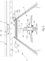
- each alert envelope A1, A2, A3 corresponds to a semi-circle projected on the ground, at the front of the aircraft AC.
- Each alert envelope A1, A2, A3 is centered on the nose 26 of the aircraft AC and has a particular radius R1, R2, R3. This radius R1, R2, R3 represents the relative distance between the nose 26 of the aircraft AC and a holding point from which the corresponding alert will be triggered (in the event of no authorization to enter the runway corresponding).
- the radius R1, R2, R3 is calculated based on a so-called incursion time.
- the incursion time is a predetermined time. It corresponds to the time given to the aircraft to reach the holding point before triggering the corresponding alert. It varies depending on the alert level. More precisely, the higher the alert level (i.e. with danger becoming more imminent), the lower the incursion time as shown in the Figure 4 for the corresponding rays R1, R2 and R3. By way of non-limiting illustration, it can for example be 3 or 4 seconds for radius R3, 6 to 8 seconds for radius R2, and 12 to 15 seconds for radius R1.
- the rays R2 and R1 are calculated from the radius R3 taking into account, each time, a predetermined corresponding reaction and decision time of the pilot.
- the verification step E3, implemented by the verification unit 11, provides (in the event of detection in the monitoring step E1 of a future entry on a track 3, 4) to check whether this future entry is authorized or unauthorized.
- the verification step E3 takes into account the entry authorization(s) received if applicable in the data reception step E2.
- the verification step E3 deduces a future incursion if this future entry is not authorized.
- the avoidance assistance step E4 implemented by the avoidance assistance unit 14, carries out (in the case of a future incursion deduced in the verification step E3) at less an action intended to help avoid (i.e. prevent) this future incursion.
- the avoidance assistance step E4 generally comprises, first of all, a sub-step E4A for transmitting one or more messages to the pilot in the cockpit of the AC aircraft.
- the message(s) transmitted may be one or more alert messages (simply alerting the pilot of the situation) and/or one or more ground navigation assistance messages (giving indications or instructions to the pilot to remedy the problem). risk of incursion, for example by asking the pilot to brake the aircraft AC).
- the alert message is adapted so that the pilot understands why system 1 triggers the incursion alert.
- the alert message issued is each time adapted to the current situation, possible transitions from one alert message to another alert message may occur over time.
- the system 1 applies a hysteresis on the transition from the emission of a first alert message to the emission of a second alert message, to avoid a possible too dynamic change and therefore appearances and disappearances. alert messages, potentially harmful to the driver.
- a first alert message for example relating to an indication or a warning
- a second alert message for example relating to a warning or an alarm
- the return that is to say the subsequent passage from the second alert message to the first alert message, will be implemented for an incursion time t1 greater than this incursion time t0.
- the system 1 checks whether the braking is sufficient to stop the aircraft before an incursion of track. If braking is sufficient, no warning message is issued. On the other hand, if braking is insufficient or if the driver stops braking, the actions required by the situation are implemented (emission of alert message and/or automatic braking).
- Sub-step E4B performs automatic braking of the aircraft, which is implemented by the braking device 25.
- the braking device 25 automatically sends a braking order to a usual braking system of the AC aircraft, and this preferably until the AC aircraft comes to a complete stop.
- the system 1 triggers a recovery action, namely an appropriate automatic braking order is calculated and supplied to the AC aircraft braking system to stop it and thus prevent an incursion onto the runway.
- This sub-step E4B therefore automatically generates braking of the aircraft, in the event of no appropriate action from the pilot after sending messages.
- This E4B substep implements protection as a last resort and in particular makes it possible to avoid the consequences that an error or incapacity of the pilot could have.
- this sub-step E4B can be implemented, even if the sub-step E4A has not been previously implemented.
Landscapes
- Engineering & Computer Science (AREA)
- Physics & Mathematics (AREA)
- General Physics & Mathematics (AREA)
- Aviation & Aerospace Engineering (AREA)
- Theoretical Computer Science (AREA)
- Multimedia (AREA)
- Computer Vision & Pattern Recognition (AREA)
- Artificial Intelligence (AREA)
- Health & Medical Sciences (AREA)
- Computing Systems (AREA)
- Databases & Information Systems (AREA)
- Evolutionary Computation (AREA)
- General Health & Medical Sciences (AREA)
- Medical Informatics (AREA)
- Software Systems (AREA)
- Traffic Control Systems (AREA)
- Radar, Positioning & Navigation (AREA)
- Remote Sensing (AREA)
- Alarm Systems (AREA)
Applications Claiming Priority (1)
| Application Number | Priority Date | Filing Date | Title |
|---|---|---|---|
| FR2213611 | 2022-12-16 |
Publications (1)
| Publication Number | Publication Date |
|---|---|
| EP4386718A1 true EP4386718A1 (de) | 2024-06-19 |
Family
ID=85278114
Family Applications (1)
| Application Number | Title | Priority Date | Filing Date |
|---|---|---|---|
| EP23214085.5A Pending EP4386718A1 (de) | 2022-12-16 | 2023-12-04 | Verfahren und system zur unterstützung der vermeidung eines starts auf einer spur durch ein auf einem flugzeug rollendes flugzeug |
Country Status (3)
| Country | Link |
|---|---|
| US (1) | US20240203274A1 (de) |
| EP (1) | EP4386718A1 (de) |
| CN (1) | CN118212820A (de) |
Citations (2)
| Publication number | Priority date | Publication date | Assignee | Title |
|---|---|---|---|---|
| US20140278037A1 (en) * | 2013-03-16 | 2014-09-18 | Hardik Choksi | Aircraft taxiing system |
| EP3109845A1 (de) * | 2015-06-24 | 2016-12-28 | Honeywell International Inc. | Flugzeugsysteme und verfahren zur verbesserung der flughafenverkehrsverwaltung |
-
2023
- 2023-12-04 EP EP23214085.5A patent/EP4386718A1/de active Pending
- 2023-12-11 US US18/535,224 patent/US20240203274A1/en active Pending
- 2023-12-15 CN CN202311734952.1A patent/CN118212820A/zh active Pending
Patent Citations (2)
| Publication number | Priority date | Publication date | Assignee | Title |
|---|---|---|---|---|
| US20140278037A1 (en) * | 2013-03-16 | 2014-09-18 | Hardik Choksi | Aircraft taxiing system |
| EP3109845A1 (de) * | 2015-06-24 | 2016-12-28 | Honeywell International Inc. | Flugzeugsysteme und verfahren zur verbesserung der flughafenverkehrsverwaltung |
Also Published As
| Publication number | Publication date |
|---|---|
| US20240203274A1 (en) | 2024-06-20 |
| CN118212820A (zh) | 2024-06-18 |
Similar Documents
| Publication | Publication Date | Title |
|---|---|---|
| EP2327067B1 (de) | Verfahren und einrichtung zum helfen beim fliegen eines flugzeugs während einer landephase | |
| EP1866890B1 (de) | Verfahren und vorrichtung zum unterstützen der bodennavigation eines flugzeugs auf einem flughafen | |
| EP3657213B1 (de) | Lernverfahren eines neuronennetzes an bord eines luftfahrzeugs für die landehilfe dieses luftfahrzeugs, und server für die umsetzung eines solchen verfahrens | |
| EP2378460A1 (de) | Fahrasistenzsystem während des Taxiing eines Flugzeuges | |
| FR2983598A1 (fr) | Procede de surveillance automatique d'operations aeriennes necessitant une garantie de performance de navigation et de guidage. | |
| FR2923614A1 (fr) | Procede de protection par signalisation d'un aeronef contre les risques de collision avec le terrain lors de procedures a couloir de protection reduit | |
| FR3050304B1 (fr) | Procede et systeme d'evitement de collision pour un aeronef suiveur d'une formation d'aeronefs par rapport a un aeronef intrus. | |
| EP2662743B1 (de) | Verfahren und Vorrichtung zur Unterstützung der Flugsteuerung eines Luftfahrzeugs während einer Landephase | |
| EP1496413A1 (de) | Hilfssystem zur Verzögerungssteuerung eines Flugzeuges im Rollvorgang | |
| FR3009117A1 (fr) | Procede et systeme d'atterrissage automatique autonome | |
| EP3451314A1 (de) | Verfahren und vorrichtung zur vermeidung eines objekts durch entdeckung seiner annäherung an ein luftfahrzeug | |
| FR3043387A1 (fr) | Procede et systeme d'aide au freinage d'un aeronef | |
| FR3003989A1 (fr) | Procede pour localiser et guider un vehicule par voie optique par rapport a un aeroport | |
| FR3013495A1 (fr) | Procede et dispositif de guidage automatique d'un aeronef roulant au sol. | |
| FR2923641A1 (fr) | Procede de protection par signalisation d'un aeronef contre les risques de collision avec le terrain lors de procedures a couloir de protection reduit avec fonctions specifiques | |
| FR3003680A1 (fr) | Procede et dispositif de determination du risque de collision au sol d'un avion | |
| FR2897976A1 (fr) | Procede et dispositif d'assistance au pilotage d'un aeronef. | |
| FR3048805A1 (fr) | Procede et dispositif d’evitement de collision pour une formation d’aeronefs par rapport a un aeronef intrus. | |
| EP4386719A1 (de) | Verfahren und system zur unterstützung eines piloten eines flugzeugs während eines flugzeugbodenlagers auf einem fahrweg eines flugzeugs | |
| EP3438949A1 (de) | Verfahren und vorrichtung zur kontrolle der flugbahn eines begleitflugzeugs in bezug auf ein leitflugzeug bei kollisionsgefahr | |
| FR2902221A1 (fr) | Procede et dispositif d'aide a la navigation au sol d'un avion sur un aeroport | |
| FR3072948A1 (fr) | Systeme d’aide a l’atterrissage d’un aeronef en phase d’approche d’une piste d’atterrissage | |
| FR2901893A1 (fr) | Dispositif de surveillance d'informations de commande d'un aeronef | |
| EP4386717A1 (de) | Verfahren und system zur unterstützung der vermeidung eines flugzeughubs eines flugzeugfahrwegs | |
| EP1465136B1 (de) | Verfahren und Vorrichtung zur Bord-Pilotenunterstützung bei Abwesenheit der Flugsicherung |
Legal Events
| Date | Code | Title | Description |
|---|---|---|---|
| PUAI | Public reference made under article 153(3) epc to a published international application that has entered the european phase |
Free format text: ORIGINAL CODE: 0009012 |
|
| STAA | Information on the status of an ep patent application or granted ep patent |
Free format text: STATUS: THE APPLICATION HAS BEEN PUBLISHED |
|
| AK | Designated contracting states |
Kind code of ref document: A1 Designated state(s): AL AT BE BG CH CY CZ DE DK EE ES FI FR GB GR HR HU IE IS IT LI LT LU LV MC ME MK MT NL NO PL PT RO RS SE SI SK SM TR |
|
| STAA | Information on the status of an ep patent application or granted ep patent |
Free format text: STATUS: REQUEST FOR EXAMINATION WAS MADE |
|
| 17P | Request for examination filed |
Effective date: 20241202 |
|
| RBV | Designated contracting states (corrected) |
Designated state(s): AL AT BE BG CH CY CZ DE DK EE ES FI FR GB GR HR HU IE IS IT LI LT LU LV MC ME MK MT NL NO PL PT RO RS SE SI SK SM TR |