EP4386494A1 - Connected watch comprising a device for common grounding of a clock movement - Google Patents
Connected watch comprising a device for common grounding of a clock movement Download PDFInfo
- Publication number
- EP4386494A1 EP4386494A1 EP22213672.3A EP22213672A EP4386494A1 EP 4386494 A1 EP4386494 A1 EP 4386494A1 EP 22213672 A EP22213672 A EP 22213672A EP 4386494 A1 EP4386494 A1 EP 4386494A1
- Authority
- EP
- European Patent Office
- Prior art keywords
- elastic ring
- watch
- conductive
- conductive elastic
- watch movement
- Prior art date
- Legal status (The legal status is an assumption and is not a legal conclusion. Google has not performed a legal analysis and makes no representation as to the accuracy of the status listed.)
- Pending
Links
- 238000003780 insertion Methods 0.000 claims abstract description 13
- 230000037431 insertion Effects 0.000 claims abstract description 13
- 238000004891 communication Methods 0.000 claims abstract description 11
- 239000004020 conductor Substances 0.000 claims abstract description 9
- 238000012545 processing Methods 0.000 claims abstract description 5
- 238000000034 method Methods 0.000 claims description 12
- 230000035939 shock Effects 0.000 claims description 9
- 238000007373 indentation Methods 0.000 claims description 5
- 239000007769 metal material Substances 0.000 claims description 5
- 239000002861 polymer material Substances 0.000 claims description 5
- 238000013016 damping Methods 0.000 claims description 4
- 230000005489 elastic deformation Effects 0.000 claims description 4
- 230000002441 reversible effect Effects 0.000 description 7
- 230000000903 blocking effect Effects 0.000 description 3
- 230000000694 effects Effects 0.000 description 3
- 208000031968 Cadaver Diseases 0.000 description 2
- 239000011231 conductive filler Substances 0.000 description 2
- 239000013078 crystal Substances 0.000 description 2
- 230000014759 maintenance of location Effects 0.000 description 2
- 238000004519 manufacturing process Methods 0.000 description 2
- 239000006096 absorbing agent Substances 0.000 description 1
- 238000010521 absorption reaction Methods 0.000 description 1
- 239000000919 ceramic Substances 0.000 description 1
- 238000006243 chemical reaction Methods 0.000 description 1
- 230000000295 complement effect Effects 0.000 description 1
- 238000005516 engineering process Methods 0.000 description 1
- 235000015243 ice cream Nutrition 0.000 description 1
- 238000009434 installation Methods 0.000 description 1
- 239000000463 material Substances 0.000 description 1
- 239000000203 mixture Substances 0.000 description 1
- 210000002445 nipple Anatomy 0.000 description 1
- 238000013519 translation Methods 0.000 description 1
Images


Classifications
-
- G—PHYSICS
- G04—HOROLOGY
- G04B—MECHANICALLY-DRIVEN CLOCKS OR WATCHES; MECHANICAL PARTS OF CLOCKS OR WATCHES IN GENERAL; TIME PIECES USING THE POSITION OF THE SUN, MOON OR STARS
- G04B17/00—Mechanisms for stabilising frequency
- G04B17/32—Component parts or constructional details, e.g. collet, stud, virole or piton
-
- G—PHYSICS
- G04—HOROLOGY
- G04G—ELECTRONIC TIME-PIECES
- G04G17/00—Structural details; Housings
- G04G17/02—Component assemblies
- G04G17/06—Electric connectors, e.g. conductive elastomers
-
- G—PHYSICS
- G04—HOROLOGY
- G04B—MECHANICALLY-DRIVEN CLOCKS OR WATCHES; MECHANICAL PARTS OF CLOCKS OR WATCHES IN GENERAL; TIME PIECES USING THE POSITION OF THE SUN, MOON OR STARS
- G04B37/00—Cases
- G04B37/04—Mounting the clockwork in the case; Shock absorbing mountings
- G04B37/0409—Fixed mounting relating to wall clocks and pendulums
- G04B37/0418—Fixed mounting relating to wall clocks and pendulums with shock damping means
-
- G—PHYSICS
- G04—HOROLOGY
- G04B—MECHANICALLY-DRIVEN CLOCKS OR WATCHES; MECHANICAL PARTS OF CLOCKS OR WATCHES IN GENERAL; TIME PIECES USING THE POSITION OF THE SUN, MOON OR STARS
- G04B43/00—Protecting clockworks by shields or other means against external influences, e.g. magnetic fields
- G04B43/002—Component shock protection arrangements
-
- G—PHYSICS
- G04—HOROLOGY
- G04B—MECHANICALLY-DRIVEN CLOCKS OR WATCHES; MECHANICAL PARTS OF CLOCKS OR WATCHES IN GENERAL; TIME PIECES USING THE POSITION OF THE SUN, MOON OR STARS
- G04B43/00—Protecting clockworks by shields or other means against external influences, e.g. magnetic fields
- G04B43/007—Antimagnetic alloys
-
- G—PHYSICS
- G04—HOROLOGY
- G04G—ELECTRONIC TIME-PIECES
- G04G17/00—Structural details; Housings
- G04G17/02—Component assemblies
- G04G17/04—Mounting of electronic components
-
- G—PHYSICS
- G04—HOROLOGY
- G04G—ELECTRONIC TIME-PIECES
- G04G17/00—Structural details; Housings
- G04G17/08—Housings
-
- G—PHYSICS
- G06—COMPUTING; CALCULATING OR COUNTING
- G06F—ELECTRIC DIGITAL DATA PROCESSING
- G06F1/00—Details not covered by groups G06F3/00 - G06F13/00 and G06F21/00
- G06F1/16—Constructional details or arrangements
- G06F1/1613—Constructional details or arrangements for portable computers
- G06F1/163—Wearable computers, e.g. on a belt
-
- G—PHYSICS
- G04—HOROLOGY
- G04D—APPARATUS OR TOOLS SPECIALLY DESIGNED FOR MAKING OR MAINTAINING CLOCKS OR WATCHES
- G04D1/00—Gripping, holding, or supporting devices
- G04D1/02—Tweezers; Vice clamps or other special hand tools for watchmakers
-
- G—PHYSICS
- G04—HOROLOGY
- G04G—ELECTRONIC TIME-PIECES
- G04G21/00—Input or output devices integrated in time-pieces
- G04G21/04—Input or output devices integrated in time-pieces using radio waves
-
- G—PHYSICS
- G04—HOROLOGY
- G04R—RADIO-CONTROLLED TIME-PIECES
- G04R60/00—Constructional details
Definitions
- the invention relates to a connected watch comprising an electronic or electromechanical watch movement having electrical or electronic components requiring common grounding.
- the watch movements of connected watches may have electrical or electronic components requiring connection to a common potential.
- grounding terminals which can be in the form of a tab of a flexible printed circuit connected to the movement.
- the casing of such a connected watch watch movement that is to say the fixing of the movement in the case, is also often carried out by means of numerous fixing flanges which are inserted into grooves provided on the internal circumference of the box, the whole being secured by flange screws.
- the invention aims to propose a connected watch comprising an electronic or electromechanical watch movement and a device for common grounding of electrical components of such a movement making it possible to resolve at least one of the aforementioned drawbacks.
- such a common grounding device is in the form of a conductive elastic ring making it possible to quickly connect different electrical components of an electronic or electromechanical watch movement.
- a conductive elastic ring according to the invention makes it possible to avoid the use of a multitude of connectors.
- the invention relates to a connected watch comprising a case having a middle part, a watch movement housed in an internal space delimited by said middle part, said watch movement comprising a processing unit and a communication module electrically connected to electrical connectors what the watch movement includes.
- the connected watch further comprises a common grounding device formed by a conductive elastic ring comprising an annular body with a central axis Z, fixing tabs carried by said annular body and cooperating with said middle part to form a locking system bayonet by relative rotation of the conductive elastic ring relative to the middle part, around the central axis Z, between an insertion position and a locked position, and in that said conductive elastic ring comprises conductive tabs configured to be in electrical contact with the electrical conductors of the watch movement when the conductive elastic ring is in the locked position in the caseband.
- the conductive tabs are elastic tabs.
- the common grounding device according to the invention also makes it possible to provide an elastic damping solution for the watch movement in the event of an impact on the watch case.
- the common grounding device also makes it possible to provide a solution for fitting the watch movement into the watch case, making it possible to avoid the use of a multitude of retaining flanges and flange tightening screw, and thus eliminates the numerous manipulations required for screws and flanges.
- the invention also relates to a mounting tool for common grounding of a watch movement of a connected watch according to the invention.
- the mounting tool comprises at least one projecting element configured to cooperate with at least one impression of the conductive elastic ring.
- the mounting tool comprises projecting elements configured to cooperate with a plurality of impressions of said conductive elastic ring, said projecting elements ensuring rotational drive of said conductive elastic ring during the rotation of said mounting tool by an operator, a automaton or a robot.
- the assembly tool comprises an unlocking pin configured to disengage said elastic locking finger when said assembly tool is in position on the conductive elastic ring so as to authorize its unlocking of said watch movement.
- the invention also relates to a method for common grounding of an electronic or electromechanical watch movement of a connected watch according to the invention.
- the fixing tabs of said conductive elastic ring come to bear on a bearing surface of said middle part.
- the common grounding step makes it possible to fit the watch movement into said watch case and maintain it in said watch case.
- the step of common grounding of the electrical connectors of the watch movement is carried out with an assembly tool comprising at least one projecting element cooperating with at least one imprint of said conductive elastic ring to engage the conductive elastic ring in rotation during rotation of the assembly tool by an operator, a controller or a robot.
- the common grounding process can be a manual process, that is to say carried out by a natural person, or an automated process.
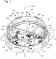
- FIG. 1 is an exploded perspective view of a connected watch 1 according to the invention comprising a box 100 of central axis B having a middle part 110 configured to be closed on either side by a box bottom (not shown) and by an ice cream (not shown).
- the connected watch 1 comprises a watch movement 10 housed in the internal space 115 delimited by the middle part 110.
- the middle part 110 is made of metallic material, ceramic, polymer material or even a mixture of different materials.
- the watch movement 10 can be an electronic or electromechanical movement.
- the watch movement 10 has a central axis A perpendicular to a general plane P1.
- the general plane P1 of the watch movement 10 is parallel to the plane of the hands (not shown).
- the central axis A of the watch movement 10 is parallel to or corresponds to the axis of rotation of the hands of the movement.
- the central axis A of the watch movement 10 is parallel to or corresponds to the central axis B of the middle part 110.
- the watch movement 10 comprises a time module, a processing unit 13 and a communication module 12, for example a Bluetooth ® type antenna.
- Such a communication module 12 requires one of its potentials to be fixed. It is therefore necessary to conductively couple one of the potentials of the communication module 12 to a common grounding device.
- the processing unit 13 and the communication module 12 have a potential electrically connected to at least one electrical connector 18 which the watch movement 10 comprises.
- the watch movement 10 comprises a plurality of electrical connectors 18 provided on the surface of the watch movement 10.
- the electrical connectors 18 are distributed around the periphery of the watch movement 10, that is to say in a region radially distant from the central axis A.
- the common ground (or common potential) of the watch movement 10 is carried out on the case back side.
- common grounding of the watch movement 10 on the crystal side is also possible without departing from the context of the invention.
- the main objective of the invention is to propose a common grounding device making it possible to facilitate this common grounding operation of the various electrical or electronic components of the watch movement 10 during the assembly of the watch movement 10 in the box 100. .
- the common grounding device according to the invention also makes it possible to simplify the fixing of the watch movement 10 to the middle part 110 during the casing operation, in particular by eliminating the use of a plurality of flanges and estimate.
- the common grounding device advantageously comprises means for ensuring the fixing, securing and locking of the watch movement 10 in the box 100.
- the common grounding device can also replace a device casing of a watch movement.
- the common grounding step of the watch movement 10 and the step of fixing the watch movement 10 in the middle part 110 are carried out simultaneously in a single locking operation of the common grounding device.
- the common grounding device is a conductive elastic ring 200.
- FIG 2 illustrates more particularly a top view of such a connected watch 1 according to the invention in which the watch movement 10 is mounted in the box 100 and the conductive elastic ring 200 is positioned above the watch movement 10 in a position of insertion (i.e. not locked). From this insertion position of the conductive elastic ring 200, a rotation of the conductive elastic ring 200 by a few degrees around the Z axis makes it possible to arrive at a locked position of the conductive elastic ring, illustrated in Figure 3 . This locked position ensures common grounding of the electrical components of the watch movement, and in particular of the communication module 12.
- the locking direction is represented by way of example in the clockwise direction by an arrow on the conductive elastic ring 200 illustrated in figure 2 .
- the locking direction can also be counterclockwise.
- FIG. 3 particularly illustrates the conductive elastic ring 200 in the locked position and electrically connected to the various electrical connectors 18 of the watch movement 10.
- Such a conductive elastic ring 200 is advantageously made of metallic material or of polymer material comprising a conductive filler.
- Such a conductive elastic ring 200 also has a shock absorber function to attenuate the effects of movements of the clock movement 10, and mainly axial movements according to the Z axis in the event of shocks on the watch case 100.
- the conductive elastic ring 200 comprises an annular body 205 with a central axis Z and fixing tabs 210 extending in a radial direction, relative to the axial direction Z.
- the central axis A of the watch movement 10 coincides with the central axis Z of the annular body 205 of the conductive elastic ring 200.
- other configurations are possible without departing from the context of the invention.
- the fixing tabs 210 conductive elastic ring 200 cooperate with bayonet grooves 113 provided in the middle part 110 to form a bayonet fitting system 300.
- a bayonet locking system 300 makes it possible to achieve common grounding, and optionally a casing of the watch movement 10 by simple relative rotation of the conductive elastic ring 200 relative to the middle part 110, around the axis Z between an insertion position (not locked) illustrated in figure 2 in which common grounding is not achieved and a locked position illustrated in Figure 3 in which the watch movement is connected to common ground, and in particular the communication module 12.
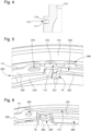
- FIG. 4 illustrates a cross-sectional view of the middle part 110 illustrating more particularly a portion having a bayonet groove 113.
- the middle part 110 comprises a bearing surface 111 forming a circular shoulder extending around the inner periphery of the middle part 110.
- the fixing tabs 210 come to rest at least partly on the bearing surface 111 of the middle part 110.
- the number of bearing surfaces 111 would preferably be equal to the number of fixing tabs 210 of the elastic casing ring 200.
- the conductive elastic ring 200 comprises six fixing tabs 210.
- the number of fixing tabs 210 is not limited to six, it could be equal to two or an arbitrary number greater than two.
- the bayonet grooves 113 are provided between the bearing surface 111 and a holding surface 114 facing the bearing surface 111.
- the number of bayonet grooves 113 is at least equal to the number of fixing tabs 210.
- the bayonet grooves 113 are arranged in a plane parallel to the general plane P1 of the watch movement 10, that is to say a plane perpendicular to the central axis A of the watch movement 10 .
- the bayonet grooves 113 can be arranged to include at least one portion with an inclination relative to the general plane P1 of the watch movement 10, so as to guide the fixing tabs 210 in rotation and in translation, and thus impose a vertical movement, along the Z axis, in the direction of the watch movement 10, of the conductive elastic ring 200 during locking by rotation around the Z axis.
- the grooves at bayonet 113 may have at least one portion with a slope directed towards the crystal of the box 100 (that is to say the side opposite the insertion of the watch movement 10 and the elastic casing ring 200) .
- the width of the bayonet grooves 113 can be constant or variable, with for example a maximum width at the level of an insertion end portion to facilitate the introduction of the fixing tabs 210, and a minimum width at the bottom of the bayonet grooves 113, for example with a width close to, or corresponding to, the thickness of the fixing tabs 210 to ensure additional retention of the fixing tabs 210 by rubbing or friction.
- the conductive elastic ring 200 comprises several elastic conductive tabs 250 in contact with the watch movement 10 acting elastically on the watch movement 10.
- the elastic conductive tabs 250 will, by counter elastic reaction, tend to maintain the fixing tabs 210 of the conductive elastic ring 200 pressed against the holding surface 114 at the level of the bayonet grooves 113.
- the bayonet grooves 113 may include a bottom, or an obstacle, for example a protuberance, to form an angular positioning stop during the rotation of the conductive elastic ring 200.
- the conductive elastic ring 200 also includes at least one mounting key 245 cooperating with a cavity 246 formed in the middle part 110 and extending axially along the Z axis.
- the conductive elastic ring 200 comprises an angular locking member 220 ensuring rotational locking of the locked position of the conductive elastic ring 200.
- the angular locking member 220 is configured to prevent loosening or unexpected unlocking of the conductive elastic ring 200, particularly in the event of shocks on the box 100.
- an angular locking member 220 makes it possible to ensure that the common grounding of the watch movement 10 will be guaranteed even during a shock suffered by the connected watch 1.
- the conductive elastic ring 200 comprises a plurality of angular locking members 220.
- FIG. 5 illustrates a portion of the conductive elastic ring 200 comprising an angular locking member 220.
- the angular locking member 220 has a portion 222 connected to the annular body 205 of the conductive elastic ring 200 at a first end.
- the portion 222 has a free end 221, opposite the first end, which is offset axially along the Z axis relative to the annular body 205.
- the free end 221 projects relative to the annular body 205 of the elastic ring conductive 200, and is directed in the direction of the watch movement 10.
- the angular locking member 220 is configured to cooperate with an elastic locking finger 230 provided at the level of the middle part 110 or the watch movement 10. Such an elastic locking finger 230 is shaped to block reverse rotation of the conductive elastic ring 200 when it comes to a stop. The ring is then in the locked position.
- the angular locking member 220 can be in the form of an asperity, for example a hole, at least formed on the lower surface of the annular body 205 (that is to say the surface intended to be opposite the watch movement 10).
- the roughness may be through or not.
- the elastic locking finger 230 provided at the level of the middle part 110 or the watch movement 10, is then shaped to be inserted at least in part in the asperity so as to block reverse rotation of the conductive elastic ring 200 when it comes to a stop. The ring is then in the locked position.
- the elastic locking finger 230 belongs to the watch movement 10, the watch movement 10 being locked in rotation in the middle part 110 by lugs, lugs, or ad hoc means, cooperating with housings provided at the level of the inner periphery of the middle part 110. These means also make it possible to form a foolproof member to guarantee the correct positioning and the correct orientation of the watch movement 10 in the middle part 110 during the assembly of the watch movement 10 in the box 100.
- the angular locking member 220 of the conductive elastic ring 200 can also form an angular positioning stop of the conductive elastic ring 200 by coming into contact with a stop surface 16 of the middle part 110 or of the watch movement 10, this which makes it possible to avoid the production of one or a plurality of angular stops in the grooves 113 of the middle part 110.
- the manufacture of such a middle part 110 is simplified.
- the angular locking member 220 and the elastic locking finger 230 form means of blocking by clipping or elastic locking of the conductive elastic ring 200.
- the means of blocking in rotation are reversible and unlockable by means of a point or an assembly/disassembly tool making it possible to constrain the elastic locking finger 230 and to deform it elastically, here in an axial direction parallel to the Z axis, to release the angular locking member 220 and the rotation of the conductive elastic ring 200, in a direction of unlocking and disassembly of the conductive elastic ring 200.
- the elastic locking finger 230 functions as a disengageable element. It is configured to be non-active when mounting the conductive elastic ring 200 and to prevent reverse rotation of the ring once it is in the locked position (operating position of the connected watch 1).
- the elastic locking finger 230 is shaped so that, in the free position, its end is positioned axially above the portion of the free end 221 of the angular locking member 220 which is furthest axially from the annular body 205.
- the elastic locking finger 230 can be either made of polymer material or of metallic material.
- the conductive elastic ring 200 comprises conductive tabs configured to come to bear on the electrical connectors 18 of the watch movement 10.
- the electrical connectors 18 are electrical tracks provided on the surface of the watch movement 10.
- the conductive tabs 250 can be shaped to exert sufficient axial force on the watch movement 10, along an axis parallel to the Z axis of the watch movement 10, to ensure its retention in the middle part 110 without having to resort to other ad hoc devices for carrying out the fitting, such as for example flanges and screws, or even a fitting circle.
- the conductive tabs 250 are elastic conductive tabs.
- Such elastic conductive tabs 250 make it possible to axially constrain the watch movement 10 in the middle part 110 to maintain it in position in the middle part 110 in normal use, while forming means of absorbing the movements, in particular, axial movements of the watch movement 10 in case of shock on the box 100.
- FIG. 6 particularly illustrates a portion of the elastic fitting ring 200 at the level of one of the elastic conductive tabs 250.
- the elastic conductive tabs 250 comprise an elastic portion 251 connected to the annular body 205 of the conductive elastic ring 200 at a first end.
- This elastic portion 251 for example in the shape of a blade, is intended to deform elastically relative to the annular body 205 of the elastic casing ring 200.
- the elastic portion 251 comprises a free contact end 252 having at least one portion 253 offset axially relative to the annular body 205 of the elastic fitting ring 200 and to the fixing tabs 210, along the axis Z.
- the free contact end 252 therefore projects relative to the annular body 205 of the elastic ring d casing 200 towards watch movement 10.
- the free contact ends 252 of the elastic conductive tabs 250 and the free end 221 of the angular locking member 220 are provided at different heights relative to the plane formed by the annular body 205.
- the free contact ends 252 of the elastic conductive tabs 250 are configured to come into contact with the various electrical connectors 18 of the watch movement 10, when the conductive elastic ring 200 is in the locked position in the middle part 110.
- the elastic conductive tabs 250 are configured to exert sufficient effort to ensure electrical contact and common grounding of the watch movement 10, even in the event of shocks to the box 100.
- the free contact ends 252 of the elastic conductive tabs 250 are configured to exert an axial force parallel to the central axis Z on the clock movement 10 when the conductive elastic ring 200 is in the locked position in the middle part 110.
- the electrical contact of all the electrical connectors 18, via the conductive elastic ring 200, is carried out by rotation of the ring 200, the rotation carrying and positioning the different elastic conductive tabs 250 in electrical contact with the electrical connectors 18.
- the common grounding of the watch movement 10 is carried out when locking the elastic casing ring 200 in a single rotation operation.
- the elastic conductive tabs 250 are configured to constrain the watch movement 10 in the middle part 110 to maintain it in position in the middle part 110 in normal use, while forming absorption or damping means attenuating the movements of the movement. watchmaking 10 in the event of an impact on the watch box 100.
- the elastic conductive tabs 250 make it possible to axially constrain the watch movement 10 along the Z axis to attenuate the effects of the axial movements of the watch movement 10 along this same axis.
- the electrical connectors 18 can be set back relative to an upper surface of the watch movement 10, configured to receive and house the elastic conductive tabs 250.
- the recessed electrical connectors 18 can thus give an indication of the positioning of the elastic conductive ring 200 and/or participate in locking the conductive elastic ring 200 in the locked position.
- the elastic conductive tabs 250 housed in these recessed electrical connectors 18 can also ensure, at least in part, blocking the movements of the watch movement 10 in the plane P1 and/or dampen or attenuate the movements of the watch movement 10 in the plane P1 .
- the conductive elastic ring 200 also includes an imprint 260, preferably at least two, configured to cooperate with projecting elements 460, such as protrusions, pins, lugs, of a mounting tool 400 for mounting (locking) and dismantling (unlocking) of the conductive elastic ring 200.
- projecting elements 460 such as protrusions, pins, lugs, of a mounting tool 400 for mounting (locking) and dismantling (unlocking) of the conductive elastic ring 200.
- the elastic ring has five indentations 260.
- the indentations 260 may be holes, notches, etc. They can be with identical or different shapes.
- the assembly tool 400 comprises a body 410 making it easier to handle, lock and unlock the conductive elastic ring 200.
- FIG 7 schematically illustrates such an assembly tool 400 according to the invention for mounting the conductive elastic ring, bringing the watch movement 10 to a common potential, and optionally fitting the watch movement 10 into the caseband 110.
- the assembly tool 400 can be in the form of a socket easily graspable by a watchmaker having at least one pin 460 configured to insert into said at least recess 260 of the conductive elastic ring 200.
- the mounting tool 400 comprises five pins 460 configured to insert into the five indentations 260 of the conductive elastic ring 200.
- the conductive elastic ring 200 further comprises a disassembly imprint 270 configured to receive and allow the passage of an unlocking pin 470 of the mounting tool 400.
- a disassembly imprint 270 preferably has a specific shape different from the other imprints 260, in particular to facilitate its identification in relation to other prints.
- other means can be used to easily identify the dismantling impression 270 from the other impressions 260 used to drive the conductive elastic ring 200 in rotation.
- the dismantling imprint 270 is for example a hole or a notch of oblong shape, while the imprints 260 can be circular in shape.
- the disassembly impression 270 is provided at the level of the annular body 205 so as to be positioned above the elastic locking finger 230 when the conductive elastic ring 200 is in the locked position in the middle part 110.
- the unlocking pin 470 of the mounting tool 400 is configured to disengage the elastic locking finger 230 when the mounting tool 400 is positioned on the conductive elastic ring.
- the unlocking pin 470 is configured to press and elastically deform the elastic locking finger 230 so as to release it from the angular locking member 220 or from the trajectory of the angular locking member 220, thus authorizing a reverse rotation of the conductive elastic ring 200.
- the mounting tool 400 is in position on the conductive elastic ring 200, it is easy to dismantle the conductive elastic ring 200 by simple rotation in the opposite direction to the direction of assembly, the latter driving the conductive elastic ring 200 in rotation by the cooperation of the nipples 460 and the impressions 260.
- the elastic conductive tabs 250 are not in electrical contact with the electrical connectors 18 of the watch movement.
- the elastic conductive tabs 250 are in contact with the electrical connectors 18 only when the conductive elastic ring 200 is locked in the middle part 110.
- the elastic conductive tabs 250 may be in contact with other non-conductive parts of the watch movement 10 in the insertion position.
- the elastic conductive tabs 250 exert a force, in particular axial, on watch movement 10 only when the elastic casing ring 200 is in the locked position.
- a first operation consists of introducing the watch movement 10 into the middle part 110 so as to match the different indexing elements of the movement 10 and the middle part 110, if present.
- the installation of the watch movement 10 can be carried out with a predefined angular position of the watch movement 10 relative to the middle part 110.
- the various indexing elements keep the watch movement 10 in rotation in the middle part 110, relative to the middle part 110. the Z axis.
- the watch movement 10 is inserted from the case back side.
- a second operation consists of introducing the conductive elastic ring 200 above the watch movement 10 until the fixing tabs 210 come to bear on the bearing surface 111 of the middle part 110.
- the conductive elastic ring 200 can be placed directly on the watch movement 10.
- a third operation consists of rotating the conductive elastic ring 200, in a determined locking direction, for example clockwise, so that the fixing tabs 210 insert into the bayonet grooves 113, up to reach a position stop via the angular positioning stop(s). The conductive elastic ring 200 is then in the locked position.
- the angular locking member 220 of the conductive elastic ring 200 cooperates with a stop surface of the clock movement 10 to form an angular positioning stop of the elastic casing ring 200.
- the angular locking member 220 of the conductive elastic ring 200 cooperates with the abutment surface 16 of the watch movement 10 to form the angular positioning stop of the conductive elastic ring 200.
- the operator may have to overcome a resistance force due to the elastic deformation of one or more elastic conductive tabs 250 engaging on the watch movement surface 10.
- the operator may have to overcome a resistance force due to the elastic deformation of one or more elastic conductive tabs 250 coming into contact with the watch movement 10 during the rotation of the ring 200, and /or overcome the resistance force by friction of the elastic conductive tab(s) 250 in contact with the watch movement 10.
- the rotation of the conductive elastic ring 200 is preferably carried out by means of the mounting tool 400 according to the invention described above.
- a fitting tool 400 makes it possible to facilitate the handling of such a conductive elastic ring 200 according to the invention.
- the method may include a preliminary step consisting of positioning the mounting tool 400 on the conductive elastic ring 200 by matching the different pins 460, 470 of the mounting tool 400 with the different respective imprints 260, 270. of the conductive elastic ring 200.
- the free end 221 of the angular locking member 220 comes into contact with the elastic locking finger 230, deforming it elastically progressively as the ring 200 rotates or from the positioning of the conductive elastic ring 200 above the watch movement 10.
- the elastic locking finger 230 is no longer constrained, the latter being able to return to its free rest position, so as to cooperate with the angular locking member 220, thus preventing the reverse rotation of the conductive elastic ring 200.
- the conductive elastic ring 200 is then locked in position.
- the elastic locking finger 230 is positioned axially (along the Z axis) opposite or above the angular locking member 220, thus preventing the reverse rotation of the conductive elastic ring 200 .
- the angular locking member 220 makes it possible, in cooperation with the elastic finger 230 of the watch movement 10, to block the locked position of the ring and to prevent any unexpected and involuntary disassembly or loosening of the conductive elastic ring 200, for example under the the effect of vibrations, successive expansion cycles, shocks, by inadvertent use of the carrier, or other.
- the passage from the insertion position to the locking position of the conductive elastic ring 200, and vice versa, is achieved by performing a rotation of around 20°.
- the rotational locking of the conductive elastic ring also ensures that the watch movement 10 is maintained in the middle part 110.
- Dismantling the conductive elastic ring preferably requires the use of an assembly tool 400 to disengage the elastic finger 230 and release the rotation of the angular locking member 220 in the unlocking direction.
- the tool mentioned during the assembly of the conductive elastic ring 200 is also used for unlocking and dismantling the conductive elastic ring 200.
- the tool 400 comprises an unlocking pin 470 configured to cooperate with the elastic locking finger 230 and force it into axial position relative to the Z axis, when the tool is held in position on the conductive elastic ring 200 by the operator.
- the method of common grounding of the watch movement 10 according to the invention makes it possible to fit the watch movement 10 into the caseband 110.
- the invention has been described with operations carried out by an operator.
- the invention is also applicable with a automaton or a robot, so that the method of common grounding of a watch movement according to the invention can be a manual process or an automated process.
Landscapes
- Physics & Mathematics (AREA)
- General Physics & Mathematics (AREA)
- Engineering & Computer Science (AREA)
- Computer Hardware Design (AREA)
- Theoretical Computer Science (AREA)
- Metallurgy (AREA)
- Human Computer Interaction (AREA)
- General Engineering & Computer Science (AREA)
- Electromechanical Clocks (AREA)
- Electric Clocks (AREA)
Abstract
Un aspect de l'invention concerne une montre connectée (1) comportant une boîte (100) présentant une carrure (110), un mouvement horloger (10) logé dans un espace interne (115) délimité par ladite carrure (110), ledit mouvement horloger (10) comportant une unité de traitement (13) et un module de communication (12) reliés électriquement à des connecteurs électriques (18) que comporte le mouvement horloger (10), ladite montre connectée (1) étant caractérisée en ce qu'elle comporte un dispositif de mise à la masse commune formé par une bague élastique conductrice (200) comportant un corps annulaire (205) d'axe central (Z), des languettes de fixation (210) portées par ledit corps annulaire (205) et coopérant avec ladite carrure (110) pour former un système de verrouillage à baïonnette (300) par rotation relative de la bague élastique conductrice (200) par rapport à la carrure (110), autour de l'axe central (Z), entre une position d'insertion et une position verrouillée, et en ce que ladite bague élastique conductrice (200) comporte des pattes conductrices (250) configurées pour être en contact électrique avec les conducteurs électriques (18) du mouvement horloger (10) lorsque la bague élastique conductrice (200) est en position verrouillée dans la carrure (110).One aspect of the invention concerns a connected watch (1) comprising a case (100) having a middle part (110), a watch movement (10) housed in an internal space (115) delimited by said middle part (110), said movement watchmaker (10) comprising a processing unit (13) and a communication module (12) electrically connected to electrical connectors (18) which the watch movement (10) comprises, said connected watch (1) being characterized in that it comprises a common grounding device formed by a conductive elastic ring (200) comprising an annular body (205) with a central axis (Z), fixing tabs (210) carried by said annular body (205) and cooperating with said middle part (110) to form a bayonet locking system (300) by relative rotation of the conductive elastic ring (200) relative to the middle part (110), around the central axis (Z), between a insertion position and a locked position, and in that said conductive elastic ring (200) comprises conductive tabs (250) configured to be in electrical contact with the electrical conductors (18) of the watch movement (10) when the elastic ring conductive (200) is in the locked position in the middle part (110).
Description
L'invention concerne une montre connectée comportant un mouvement horloger électronique ou électromécanique présentant des organes électriques ou électroniques nécessitant une mise à la masse commune.The invention relates to a connected watch comprising an electronic or electromechanical watch movement having electrical or electronic components requiring common grounding.
Les mouvements horlogers des montres connectées peuvent présenter des organes électriques ou électroniques nécessitant une mise à un potentiel commun.The watch movements of connected watches may have electrical or electronic components requiring connection to a common potential.
La mise à un potentiel commun de tels organes électriques est classiquement réalisée avec des bornes de mise à la masse pouvant être sous la forme d'une languette d'un circuit imprimé flexible relié au mouvement.Bringing such electrical members to a common potential is conventionally carried out with grounding terminals which can be in the form of a tab of a flexible printed circuit connected to the movement.
Toutefois, cela n'est pas toujours suffisant, notamment lorsque le mouvement horloger intègre un module de communication, par exemple de type antenne Bluetooth®.However, this is not always sufficient, particularly when the watch movement integrates a communication module, for example of the Bluetooth ® antenna type.
La mise à un potentiel commun d'un tel module de communication nécessite la multiplication des connecteurs, ce qui complexifie la mise en oeuvre en raison des nombreuses pièces, l'opération d'emboitage du mouvement et de mise à la masse notamment par les différentes manipulations requises pour le placement des différents connecteurs. Ainsi, la productivité d'une telle solution de mise à un potentiel commun est grandement affectée.Bringing such a communication module to a common potential requires the multiplication of connectors, which complicates the implementation due to the numerous parts, the operation of fitting the movement and grounding in particular by the different manipulations required for the placement of the different connectors. Thus, the productivity of such a common potential solution is greatly affected.
De plus, cette opération de mise à un potentiel commun est généralement réalisée lors de l'emboitage du mouvement dans la boîte de la montre connectée.In addition, this operation of setting a common potential is generally carried out when fitting the movement into the case of the connected watch.
L'emboitage d'un tel mouvement horloger de montre connectée, c'est-à-dire la fixation du mouvement dans la boîte, est également souvent réalisé au moyen de nombreuses brides de fixation qui viennent s'insérer dans des rainures prévues sur la circonférence interne de la boîte, l'ensemble étant solidarisé par des vis de bride.The casing of such a connected watch watch movement, that is to say the fixing of the movement in the case, is also often carried out by means of numerous fixing flanges which are inserted into grooves provided on the internal circumference of the box, the whole being secured by flange screws.
Par conséquent, cette opération d'emboitage dans son ensemble est une opération longue et complexe à mettre oeuvre en raison des nombreuses pièces (connecteurs, brides, vis, ...), et des différentes manipulations requises pour le placement des connecteurs, des brides et des vis, ce qui affecte grandement la productivité d'une telle solution d'emboitage et de mise à un potentiel commun d'un mouvement d'horlogerie de montre connectée.Consequently, this casing operation as a whole is a long and complex operation to implement due to the numerous parts (connectors, flanges, screws, etc.), and the different manipulations required for the placement of the connectors, flanges and screws, which greatly affects the productivity of such a casing solution and bringing a connected watch movement to a common potential.
Par conséquent, il existe un besoin pour améliorer les dispositifs de mise à un potentiel commun d'un mouvement d'horlogerie électronique ou électromécanique d'une montre connectée, notamment pour améliorer l'opération globale d'emboitage.Consequently, there is a need to improve the devices for bringing an electronic or electromechanical watch movement of a connected watch to a common potential, in particular to improve the overall casing operation.
A cette fin, l'invention vise à proposer une montre connectée comportant un mouvement d'horlogerie électronique ou électromécanique et un dispositif de mise à la masse commune d'organes électriques d'un tel mouvement permettant de résoudre au moins un des inconvénients précités.To this end, the invention aims to propose a connected watch comprising an electronic or electromechanical watch movement and a device for common grounding of electrical components of such a movement making it possible to resolve at least one of the aforementioned drawbacks.
Selon l'invention, un tel dispositif de mise à la masse commune se présente sous la forme d'une bague élastique conductrice permettant de connecter rapidement différents organes électriques d'un mouvement d'horlogerie électronique ou électromécanique. Une telle bague élastique conductrice selon l'invention permet de s'affranchir de l'utilisation d'une multitude de connecteurs.According to the invention, such a common grounding device is in the form of a conductive elastic ring making it possible to quickly connect different electrical components of an electronic or electromechanical watch movement. Such a conductive elastic ring according to the invention makes it possible to avoid the use of a multitude of connectors.
Dans ce contexte, l'invention concerne une montre connectée comportant une boîte présentant une carrure, un mouvement horloger logé dans un espace interne délimité par ladite carrure, ledit mouvement horloger comportant une unité de traitement et un module de communication reliés électriquement à des connecteurs électriques que comporte le mouvement horloger.In this context, the invention relates to a connected watch comprising a case having a middle part, a watch movement housed in an internal space delimited by said middle part, said watch movement comprising a processing unit and a communication module electrically connected to electrical connectors what the watch movement includes.
La montre connectée comporte en outre un dispositif de mise à la masse commune formé par une bague élastique conductrice comportant un corps annulaire d'axe central Z, des languettes de fixation portées par ledit corps annulaire et coopérant avec ladite carrure pour former un système de verrouillage à baïonnette par rotation relative de la bague élastique conductrice par rapport à la carrure, autour de l'axe central Z, entre une position d'insertion et une position verrouillée, et en ce que ladite bague élastique conductrice comporte des pattes conductrices configurées pour être en contact électrique avec les conducteurs électriques du mouvement horloger lorsque la bague élastique conductrice est en position verrouillée dans la carrure.The connected watch further comprises a common grounding device formed by a conductive elastic ring comprising an annular body with a central axis Z, fixing tabs carried by said annular body and cooperating with said middle part to form a locking system bayonet by relative rotation of the conductive elastic ring relative to the middle part, around the central axis Z, between an insertion position and a locked position, and in that said conductive elastic ring comprises conductive tabs configured to be in electrical contact with the electrical conductors of the watch movement when the conductive elastic ring is in the locked position in the caseband.
Préférentiellement, les pattes conductrices sont des pattes élastiques. Ainsi, le dispositif de mise à la masse commune selon l'invention permet également d'apporter une solution d'amortissement élastique du mouvement d'horlogerie en cas de choc sur la boîte de montre.Preferably, the conductive tabs are elastic tabs. Thus, the common grounding device according to the invention also makes it possible to provide an elastic damping solution for the watch movement in the event of an impact on the watch case.
Le dispositif de mise à la masse commune selon l'invention permet également d'apporter une solution d'emboitage du mouvement horloger dans la boîte de montre, permettant de s'affranchir de l'utilisation d'une multitude de brides de maintien et de vis de serrage de bride, et permet ainsi de s'affranchir des nombreuses manipulations requises pour les vis et les brides.The common grounding device according to the invention also makes it possible to provide a solution for fitting the watch movement into the watch case, making it possible to avoid the use of a multitude of retaining flanges and flange tightening screw, and thus eliminates the numerous manipulations required for screws and flanges.
Outre les caractéristiques évoquées dans les paragraphes précédents, la montre connectée selon l'invention peut présenter une ou plusieurs caractéristiques complémentaires parmi les suivantes, considérées individuellement ou selon toutes les combinaisons techniquement possibles :
- les conducteurs électriques sont des pistes électriques ménagées en surface dudit mouvement horloger et en ce que les pattes conductrices de la bague élastique conductrice sont en appui sur les pistes électriques lorsque la bague élastique conductrice est en position verrouillée dans la carrure ;
- les pattes conductrices sont des pattes conductrices élastiques ;
- les pattes conductrices sont configurées pour exercer un effort axial parallèlement à l'axe central Z sur le mouvement horloger par déformation élastique des pattes élastiques conductrices au moins lorsque ladite bague élastique d'emboitage est en position verrouillée dans la carrure ;
- lesdites pattes conductrices sont configurées pour que l'effort axial exercé sur le mouvement horloger assure un maintien dudit mouvement horloger dans ladite carrure ; préférentiellement selon une direction axiale parallèle à l'axe central Z ;
- lesdites pattes conductrices sont configurées pour former des moyens amortisseurs du mouvement horloger en cas de chocs subis par la montre connectée ; préférentiellement selon une direction axiale parallèle à l'axe central Z ;
- les languettes de fixation s'étendent radialement par rapport à l'axe central Z ;
- chacune desdites pattes conductrices comporte une portion élastique reliée au corps annulaire et est conformée pour se déformer élastiquement ;
- ladite portion élastique comporte une extrémité libre de contact présentant au moins une portion décalée axialement, selon l'axe central Z, par rapport au corps annulaire, ladite extrémité libre de contact étant en contact électrique avec un des conducteurs électriques du mouvement horloger, lorsque ladite bague élastique conductrice est en position verrouillée dans la carrure ;
- la bague élastique conductrice comporte un organe de verrouillage angulaire coopérant avec un doigt élastique de verrouillage porté par le mouvement horloger ou par la carrure, pour assurer un verrouillage en rotation de ladite bague élastique conductrice une fois en position verrouillée par clippage ou verrouillage élastique ;
- l'organe de verrouillage angulaire coopère avec une surface de butée du mouvement horloger ou de la carrure pour former une butée angulaire de positionnement de la bague élastique conductrice ;
- la carrure comporte une surface d'appui pour recevoir en appui lesdites languettes de fixation de la bague élastique conductrice ;
- la carrure comporte des rainures à baïonnette, lesdites rainures à baïonnette coopérant avec lesdites languettes de fixation pour former le système de verrouillage à baïonnette ;
- ladite bague élastique conductrice comporte un détrompeur de montage ;
- ladite bague élastique conductrice comporte au moins une empreinte présentant une forme adaptée pour coopérer avec un outil de montage ;
- ladite bague élastique conductrice comporte une première empreinte configurée pour assurer la rotation de la bague élastique conductrice et une deuxième empreinte configurée pour assurer le déverrouillage de ladite bague élastique conductrice, chacune des empreintes présentant une forme adaptée pour coopérer avec un outil de montage ;
- la bague élastique conductrice est réalisée en matière métallique ou en matière polymère avec une charge conductrice.
- the electrical conductors are electrical tracks provided on the surface of said watch movement and in that the conductive tabs of the conductive elastic ring bear on the electrical tracks when the conductive elastic ring is in the locked position in the caseband;
- the conductive legs are elastic conductive legs;
- the conductive tabs are configured to exert an axial force parallel to the central axis Z on the watch movement by elastic deformation of the conductive elastic tabs at least when said elastic casing ring is in the locked position in the middle part;
- said conductive tabs are configured so that the axial force exerted on the watch movement ensures that said watch movement is maintained in said caseband; preferably in an axial direction parallel to the central axis Z;
- said conductive tabs are configured to form damping means for the watch movement in the event of shocks suffered by the connected watch; preferably in an axial direction parallel to the central axis Z;
- the fixing tabs extend radially relative to the central axis Z;
- each of said conductive tabs comprises an elastic portion connected to the annular body and is shaped to deform elastically;
- said elastic portion comprises a free contact end having at least one portion offset axially, along the central axis Z, relative to the annular body, said free contact end being in electrical contact with one of the conductors electrical of the watch movement, when said conductive elastic ring is in the locked position in the caseband;
- the conductive elastic ring comprises an angular locking member cooperating with an elastic locking finger carried by the watch movement or by the caseband, to ensure rotational locking of said conductive elastic ring once in the locked position by clipping or elastic locking;
- the angular locking member cooperates with a stop surface of the watch movement or the caseband to form an angular stop for positioning the conductive elastic ring;
- the middle part includes a bearing surface to receive said fixing tabs of the conductive elastic ring in support;
- the middle part has bayonet grooves, said bayonet grooves cooperating with said fixing tabs to form the bayonet locking system;
- said conductive elastic ring comprises a mounting key;
- said conductive elastic ring comprises at least one cavity having a shape adapted to cooperate with a mounting tool;
- said conductive elastic ring comprises a first cavity configured to ensure the rotation of the conductive elastic ring and a second cavity configured to ensure the unlocking of said conductive elastic ring, each of the cavity having a shape adapted to cooperate with a mounting tool;
- the conductive elastic ring is made of metallic material or polymer material with a conductive filler.
L'invention concerne également un outil de montage pour la mise à la masse commune d'un mouvement d'horlogerie d'une montre connectée selon l'invention.The invention also relates to a mounting tool for common grounding of a watch movement of a connected watch according to the invention.
L'outil de montage comporte au moins un élément en saillie configuré pour coopérer avec au moins une empreinte de la bague élastique conductrice.The mounting tool comprises at least one projecting element configured to cooperate with at least one impression of the conductive elastic ring.
Préférentiellement, l'outil de montage comporte des éléments en saillie configurés pour coopérer avec une pluralité d'empreintes de ladite bague élastique conductrice, lesdits éléments en saillie assurant un entrainement en rotation de ladite bague élastique conductrice lors de la rotation dudit outil de montage par un opérateur, un automate ou un robot.Preferably, the mounting tool comprises projecting elements configured to cooperate with a plurality of impressions of said conductive elastic ring, said projecting elements ensuring rotational drive of said conductive elastic ring during the rotation of said mounting tool by an operator, a automaton or a robot.
Avantageusement, l'outil de montage comporte un téton de déverrouillage configuré pour débrayer ledit doigt élastique de verrouillage lorsque ledit outil de montage est en position sur la bague élastique conductrice de manière à autoriser son déverrouillage dudit mouvement horloger.Advantageously, the assembly tool comprises an unlocking pin configured to disengage said elastic locking finger when said assembly tool is in position on the conductive elastic ring so as to authorize its unlocking of said watch movement.
L'invention concerne également un procédé de mise à la masse commune d'un mouvement horloger électronique ou électromécanique d'une montre connectée selon l'invention.The invention also relates to a method for common grounding of an electronic or electromechanical watch movement of a connected watch according to the invention.
Le procédé de mise à la masse commune selon l'invention comporte :
- une étape d'introduction dudit mouvement horloger dans la carrure de la boîte ;
- une étape d'introduction du dispositif de mise à la masse commune, formé par ladite bague élastique conductrice, par-dessus le mouvement d'horlogerie
- une étape de mise à la masse commune des connecteurs électriques du mouvement horloger durant laquelle la bague élastique conductrice est engagée en rotation autour de l'axe central Z jusqu'à atteindre une position verrouillée, la rotation engageant lesdites languettes de fixation dans une pluralité de rainures à baïonnette que comporte la carrure, lesdites pattes conductrices venant en contact électrique avec les conducteurs électriques du mouvement horloger lorsque la bague élastique conductrice est en position verrouillée.
- a step of introducing said watch movement into the middle of the case;
- a step of introducing the common grounding device, formed by said conductive elastic ring, over the watch movement
- a step of common grounding of the electrical connectors of the watch movement during which the conductive elastic ring is engaged in rotation around the axis central Z until reaching a locked position, the rotation engaging said fixing tabs in a plurality of bayonet grooves that the middle part has, said conductive tabs coming into electrical contact with the electrical conductors of the watch movement when the conductive elastic ring is in locked position.
Préférentiellement, lors de l'étape d'introduction du dispositif de mise à la masse commune, formé par ladite bague élastique conductrice, les languettes de fixation de ladite bague élastique conductrice viennent en appui sur une surface d'appui de ladite carrure.Preferably, during the step of introducing the common grounding device, formed by said conductive elastic ring, the fixing tabs of said conductive elastic ring come to bear on a bearing surface of said middle part.
Préférentiellement, l'étape de mise à la masse commune permet de réaliser un emboitage du mouvement horloger dans ladite boîte de montre et son maintien dans ladite boîte de montre.Preferably, the common grounding step makes it possible to fit the watch movement into said watch case and maintain it in said watch case.
Préférentiellement, l'étape de mise à la masse commune des connecteurs électriques du mouvement horloger est réalisée avec un outil de montage comportant au moins un élément en saillie coopérant avec au moins une empreinte de ladite bague élastique conductrice pour engager en rotation la bague élastique conductrice lors de la rotation de l'outil de montage par un opérateur, un automate ou un robot.Preferably, the step of common grounding of the electrical connectors of the watch movement is carried out with an assembly tool comprising at least one projecting element cooperating with at least one imprint of said conductive elastic ring to engage the conductive elastic ring in rotation during rotation of the assembly tool by an operator, a controller or a robot.
Le procédé de mise à la masse commune peut être un procédé manuel, c'est-à-dire réalisé par une personne physique ou un procédé automatisé.The common grounding process can be a manual process, that is to say carried out by a natural person, or an automated process.
Les buts, avantages et caractéristiques de la présente invention apparaîtront à la lecture de la description détaillée ci-dessous faisant référence aux figures suivantes :
- la
figure 1 est une vue semi-éclatée en perspective d'une montre connectée selon l'invention comportant une boîte présentant une carrure, un mouvement horloger monté dans la carrure et un dispositif de mise à la masse commune pour assurer la mise à la masse du mouvement horloger ; - la
figure 2 est une vue de dessus de la montre connectée selon l'invention illustrée à lafigure 1 ; lafigure 2 illustrant particulièrement le dispositif de mise à la masse commune dans sa position d'insertion ; - la
figure 3 est une vue de dessus de la montre connectée selon l'invention illustrée à lafigure 1 , lafigure 3 illustrant particulièrement le dispositif de mise à la masse commune dans sa position verrouillée dans la carrure ; - la
figure 4 est en vue en coupe transversale de la carrure selon l'invention au niveau d'une rainure à baïonnette ; - la
figure 5 est une vue de détail du dispositif de mise à la masse commune selon l'invention illustrant plus particulièrement un organe de verrouillage angulaire du dispositif de mise à la masse commune ; - la
figure 6 est une vue de détail du dispositif de mise à la mase commune selon l'invention illustrant plus particulièrement une patte élastique de contact électrique ; - la
figure 7 est une représentation schématique d'un outil de montage/démontage pour la mise à la masse commune d'un mouvement horlogerie au moyen du dispositif de mise à la masse commune l'invention.
- there
figure 1 is a semi-exploded perspective view of a connected watch according to the invention comprising a box having a middle, a watch movement mounted in the middle and a common grounding device to ensure the grounding of the watch movement; - there
figure 2 is a top view of the connected watch according to the invention illustrated infigure 1 ; therefigure 2 particularly illustrating the common grounding device in its insertion position; - there
Figure 3 is a top view of the connected watch according to the invention illustrated infigure 1 , thereFigure 3 particularly illustrating the common grounding device in its locked position in the caseband; - there
Figure 4 is in cross-sectional view of the middle part according to the invention at the level of a bayonet groove; - there
Figure 5 is a detailed view of the common grounding device according to the invention illustrating more particularly an angular locking member of the common grounding device; - there
Figure 6 is a detailed view of the common grounding device according to the invention illustrating more particularly an elastic electrical contact tab; - there
figure 7 is a schematic representation of an assembly/disassembly tool for common grounding of a watch movement by means of the common grounding device of the invention.
Dans toutes les figures, les éléments communs portent les mêmes numéros de référence sauf précision contraire.In all figures, common elements bear the same reference numbers unless otherwise specified.
La
La montre connectée 1 comporte un mouvement horloger 10 logé dans l'espace interne 115 délimité par la carrure 110.The
Par exemple, la carrure 110 est en matière métallique, céramique, en matière polymère ou encore un mixte de différentes matières.For example, the
Le mouvement horloger 10 peut être un mouvement électronique ou électromécanique.The
Le mouvement horloger 10 présente un axe central A perpendiculaire à un plan général P1. Le plan général P1 du mouvement d'horlogerie 10 est parallèle au plan des aiguilles (non représentées). L'axe central A du mouvement d'horlogerie 10 est parallèle ou correspond à l'axe de rotation des aiguilles du mouvement.The
L'axe central A du mouvement d'horlogerie 10 est parallèle ou correspond à l'axe central B de la carrure 110.The central axis A of the
Préférentiellement, le mouvement horloger 10 comporte un module horaire, une unité de traitement 13 et un module de communication 12, par exemple une antenne de type Bluetooth®.Preferably, the
Un tel module de communication 12 nécessite d'avoir un de ses potentiels fixe. Il est donc nécessaire de coupler de manière conductrice un des potentiels du module de communication 12 à un dispositif de mise à la masse commune.Such a
Bien entendu, d'autres organes électriques ou électroniques que comporte le mouvement horloger 10 peuvent également nécessiter une mise à la masse commune.Of course, other electrical or electronic components included in the
L'unité de traitement 13 et le module de communication 12 présentent un potentiel relié électriquement à au moins un connecteur électrique 18 que comporte le mouvement horloger 10.The
Préférentiellement, le mouvement horloger 10 comporte une pluralité de connecteurs électriques 18 ménagés à la surface du mouvement horloger 10.Preferably, the
Préférentiellement, les connecteurs électriques 18 sont répartis en périphérie du mouvement horloger 10, c'est-à-dire dans une région radialement éloignée de l'axe central A.Preferably, the
Dans l'exemple de réalisation illustré, la mise à la masse commune (ou potentiel commun) du mouvement horloger 10 est réalisé côté fond de boîte. Bien entendu, une mise à la masse commune du mouvement horloger 10 côté glace est également possible sans sortir du contexte de l'invention.In the illustrated embodiment, the common ground (or common potential) of the
L'objectif principal de l'invention est de proposer un dispositif de mise à la masse commune permettant faciliter cette opération de mise à la masse commune des divers organes électriques ou électroniques du mouvement horloger 10 lors du montage du mouvement horloger 10 dans la boîte 100.The main objective of the invention is to propose a common grounding device making it possible to facilitate this common grounding operation of the various electrical or electronic components of the
Le dispositif de mise à la masse commune selon l'invention permet également de simplifier la fixation du mouvement horloger 10 à la carrure 110 lors de l'opération d'emboitage, notamment par la suppression de l'utilisation d'une pluralité de brides et de vis.The common grounding device according to the invention also makes it possible to simplify the fixing of the
Le dispositif de mise à la masse commune selon l'invention comporte avantageusement des moyens pour assurer la fixation, la sécurisation et le verrouillage du mouvement horloger 10 dans la boîte 100. Ainsi, le dispositif de mise à la masse commune peut également remplacer un dispositif d'emboitage d'un mouvement horloger.The common grounding device according to the invention advantageously comprises means for ensuring the fixing, securing and locking of the
Ainsi, grâce à un tel dispositif de mise à la masse commune selon l'invention, l'étape de mise à la masse commune du mouvement horloger 10 et l'étape de fixation du mouvement horloger 10 dans la carrure 110 sont réalisées simultanément en une seule opération de verrouillage du dispositif de mise à la masse commune.Thus, thanks to such a common grounding device according to the invention, the common grounding step of the
Selon l'invention, le dispositif de mise à la masse commune est une bague élastique conductrice 200.According to the invention, the common grounding device is a conductive
La
Le sens de verrouillage est représenté à titre d'exemple dans le sens horaire par une flèche sur la bague élastique conductrice 200 illustrée à la
La
Une telle bague élastique conductrice 200 est avantageusement en matière métallique ou en matière polymère comportant une charge conductrice.Such a conductive
Une telle bague élastique conductrice 200 présente également une fonction d'amortisseur pour atténuer les effets des déplacements du mouvement d'horlogerie 10, et principalement les déplacements axiaux selon l'axe Z en cas de chocs sur la boîte de montre 100.La bague élastique conductrice 200 comporte un corps annulaire 205 d'axe central Z et des languettes de fixation 210 s'étendant selon une direction radiale, par rapport à la direction axiale Z.Such a conductive
Dans l'exemple de réalisation représenté, l'axe central A du mouvement d'horlogerie 10 est confondu avec l'axe central Z du corps annulaire 205 de la bague élastique conductrice 200. Toutefois, d'autres configurations sont possibles sans sortir du contexte de l'invention.In the embodiment shown, the central axis A of the
Les languettes de fixation 210 bague élastique conductrice 200 coopèrent avec des rainures à baïonnette 113 ménagées dans la carrure 110 pour former un système d'emboitage à baïonnette 300. Une tel système de verrouillage à baïonnette 300 permet de réaliser une mise à la masse commune, et optionnellement un emboitage, du mouvement horloger 10 par simple rotation relative de la bague élastique conductrice 200 par rapport à la carrure 110, autour de l'axe Z entre une position d'insertion (non verrouillée) illustrée à la
La
Pour recevoir la bague élastique conductrice 200, la carrure 110 comporte une surface d'appui 111 formant un épaulement circulaire s'étendant sur le pourtour intérieur de la carrure 110.To receive the conductive
Plus particulièrement, lors de l'insertion de la bague élastique conductrice 200 dans la carrure 110, les languettes de fixation 210 viennent se poser au moins en partie sur la surface d'appui 111 de la carrure 110.More particularly, when inserting the conductive
De manière générale, les termes « interne », « intérieur », « externe » et « extérieur » sont bien entendu à comprendre par rapport à la direction axiale Z illustrée à la
Selon une variante de réalisation, il est possible d'agencer une pluralité de surfaces d'appui 111 s'étendant sur des portions angulaires du pourtour intérieur de la carrure 110 et reparties uniformément, ou non, sur le pourtour intérieur de la carrure 110. Dans cette variante de réalisation, le nombre de surfaces d'appui 111 serait préférentiellement égal au nombre de languettes de fixation 210 de la bague élastique d'emboitage 200.According to a variant embodiment, it is possible to arrange a plurality of support surfaces 111 extending over angular portions of the inner periphery of the
Dans l'exemple de réalisation illustré, la bague élastique conductrice 200 comporte six languettes de fixation 210. Toutefois, le nombre de languettes de fixation 210 n'est pas limité à six, il pourrait être égal à deux ou à un nombre arbitraire supérieur à deux. Les rainures à baïonnette 113 sont ménagées entre la surface d'appui 111 et une surface de maintien 114 faisant face à la surface d'appui 111.In the illustrated embodiment, the conductive
Le nombre de rainures à baïonnette 113 est au moins égal au nombre de languettes de fixation 210.The number of
Dans l'exemple de réalisation illustré, les rainures à baïonnette 113 sont agencées dans un plan parallèle au plan général P1 du mouvement horloger 10, c'est-à-dire un plan perpendiculaire à l'axe central A du mouvement d'horlogerie 10.In the illustrated embodiment, the
Dans une variante de réalisation, les rainures à baïonnette 113 peuvent être agencées pour comporter au moins une portion avec une inclinaison par rapport au plan général P1 du mouvement horloger 10, de manière à guider en rotation et en translation les languettes de fixation 210, et ainsi imposer un déplacement vertical, selon l'axe Z, en direction du mouvement horloger 10, de la bague élastique conductrice 200 lors du verrouillage par rotation autour de l'axe Z. Par exemple, les rainures à baïonnette 113 peuvent présenter au moins une portion avec une déclivité dirigée vers la glace de la boîte 100 (c'est-à-dire le côté opposé à l'insertion du mouvement d'horlogerie 10 et de la bague élastique d'emboitage 200).In a variant embodiment, the
L'espace entre la surface d'appui 111 et la surface de maintien 114 délimite la largeur de la rainure à baïonnette 113. Bien entendu, la largeur des rainures à baïonnette 113 peut être constante ou variable, avec par exemple une largeur maximale au niveau d'une portion d'extrémité d'insertion pour faciliter l'introduction des languettes de fixation 210, et une largeur minimale au niveau du fond des rainures à baïonnette 113, par exemple avec une largeur proche, ou correspondant, à l'épaisseur des languettes de fixation 210 pour assurer un maintien supplémentaire des languettes de fixation 210 par frottement ou friction.The space between the
Toutefois, comme nous le verrons par la suite, un tel arrangement n'est pas indispensable car la bague élastique conductrice 200 selon l'invention comporte plusieurs pattes conductrices élastiques 250 en contact avec le mouvement horloger 10 agissant élastiquement sur le mouvement horloger 10. Ainsi, les pattes conductrices élastiques 250 vont, par contre réaction élastique, tendre à maintenir les languettes de fixation 210 de la bague élastique conductrice 200 plaquées contre la surface de maintien 114 au niveau des rainures à baïonnette 113.However, as we will see later, such an arrangement is not essential because the conductive
Les rainures à baïonnette 113 peuvent comporter un fond, ou un obstacle, par exemple une protubérance, pour former une butée angulaire de positionnement lors de la rotation de la bague élastique conductrice 200.The
La bague élastique conductrice 200 comporte également au moins un détrompeur de montage 245 coopérant avec une cavité 246 ménagée dans la carrure 110 et s'étendant axialement le long de l'axe Z.The conductive
La bague élastique conductrice 200 comporte un organe de verrouillage angulaire 220 assurant un blocage en rotation de la position verrouillée de la bague élastique conductrice 200. L'organe de verrouillage angulaire 220 est configuré pour empêcher un desserrage ou un déverrouillage inopiné de la bague élastique conductrice 200, notamment en cas de chocs sur la boîte 100. Ainsi, un tel organe de verrouillage angulaire 220 permet de s'assurer que la mise à la masse commune du mouvement horloger 10 sera garantie même lors d'un choc subi par la montre connectée 1.The conductive
Selon une variante de réalisation, la bague élastique conductrice 200 comporte une pluralité d'organes de verrouillage angulaire 220.According to a variant embodiment, the conductive
La
Dans une première variante de réalisation, telle qu'illustrée, l'organe de verrouillage angulaire 220 présente une portion 222 raccordée au corps annulaire 205 de la bague élastique conductrice 200 au niveau d'une première extrémité. La portion 222 présente une extrémité libre 221, opposée à la première extrémité, qui est décalée axialement selon l'axe Z par rapport au corps annulaire 205. Ainsi, l'extrémité libre 221 fait saillie par rapport au corps annulaire 205 de la bague élastique conductrice 200, et est dirigée en direction du mouvement horloger 10.In a first alternative embodiment, as illustrated, the
L'organe de verrouillage angulaire 220 est configuré pour coopérer avec un doigt élastique de verrouillage 230 ménagé au niveau de la carrure 110 ou du mouvement horloger 10. Un tel doigt élastique de verrouillage 230 est conformé pour bloquer une rotation inverse de la bague élastique conductrice 200 lorsque celle-ci arrive en butée. La bague est alors en position verrouillée.The
Dans une deuxième variante de réalisation, l'organe de verrouillage angulaire 220 peut être sous la forme d'une aspérité, par exemple un trou, au moins ménagée sur la surface inférieure du corps annulaire 205 (c'est-à-dire la surface destinée à être en regard du mouvement horloger 10). L'aspérité peut être traversante ou non. Le doigt élastique de verrouillage 230, ménagé au niveau de la carrure 110 ou du mouvement horloger 10, est alors conformé pour venir s'insérer au moins en partie dans l'aspérité de manière à bloquer une rotation inverse de la bague élastique conductrice 200 lorsque celle-ci arrive en butée. La bague est alors en position verrouillée.In a second alternative embodiment, the
Dans l'exemple de réalisation illustré, le doigt élastique de verrouillage 230 appartient au mouvement horloger 10, le mouvement horloger 10 étant bloqué en rotation dans la carrure 110 par des ergots, oreilles, ou moyens ad hoc, coopérant avec des logements ménagés au niveau du pourtour intérieur de la carrure 110. Ces moyens permettent également de former un organe détrompeur pour garantir le bon positionnement et la bonne orientation du mouvement horloger 10 dans la carrure 110 lors du montage du mouvement horloger 10 dans la boîte 100.In the illustrated embodiment, the
Comme illustré à la
L'organe de verrouillage angulaire 220 et le doigt élastique de verrouillage 230 forment des moyens de blocage par clippage ou verrouillage élastique de la bague élastique conductrice 200. Les moyens de blocage en rotation sont réversibles et déverrouillables au moyen d'une pointe ou d'un outil de montage/démontage permettant de contraindre le doigt élastique de verrouillage 230 et de le déformer élastiquement, ici selon une direction axiale parallèle à l'axe Z, pour libérer l'organe de verrouillage angulaire 220 et la rotation de la bague élastique conductrice 200, dans un sens de déverrouillage et de démontage de la bague élastique conductrice 200.The
Le doigt élastique de verrouillage 230 fonctionne comme un élément débrayable. Il est configuré pour être non actif lors du montage de la bague élastique conductrice 200 et pour empêcher une rotation inverse de la bague une fois que celle-ci est en position verrouillée (position de fonctionnement de la montre connectée 1).The
Plus particulièrement, dans la variante de réalisation illustrée, le doigt élastique de verrouillage 230 est conformé pour que, en position libre, son extrémité se positionne axialement au-dessus de la portion de l'extrémité libre 221 de l'organe de verrouillage angulaire 220 qui est la plus éloignée axialement du corps annulaire 205.More particularly, in the illustrated alternative embodiment, the
Le doigt élastique de verrouillage 230 peut être indifféremment en matière polymère ou en matière métallique.The
La bague élastique conductrice 200 comporte des pattes conductrices configurées pour venir en appui sur les connecteurs électriques 18 du mouvement horloger 10. Par exemple, les connecteurs électriques 18 sont des pistes électriques ménagées en surface du mouvement horloger 10.The conductive
Optionnellement, les pattes conductrices 250 peuvent être conformées pour exercer un effort axial suffisant sur le mouvement horloger 10, selon un axe parallèle à l'axe Z du mouvement horloger 10, pour assurer son maintien dans la carrure 110 sans avoir recours à d'autres dispositifs ad hoc pour la réalisation de l'emboitage, comme par exemple des brides et des vis, ou encore un cercle d'emboitage.Optionally, the
Avantageusement, les pattes conductrices 250 sont des pattes conductrices élastiques.Advantageously, the
De telles pattes conductrices élastiques 250 permettent de contraindre axialement le mouvement horloger 10 dans la carrure 110 pour le maintenir en position dans la carrure 110 en utilisation normale, tout en formant des moyens d'absorption des mouvements, notamment, axiaux du mouvement horloger 10 en cas de chocs sur la boîte 100.Such elastic
La
Les pattes conductrices élastiques 250 comportent une portion élastique 251 raccordée au corps annulaire 205 de la bague élastique conductrice 200 au niveau d'une première extrémité. Cette portion élastique 251, par exemple en forme de lame, est destinée à se déformer élastiquement par rapport au corps annulaire 205 de la bague élastique d'emboitage 200. La portion élastique 251 comporte une extrémité libre de contact 252 présentant au moins une portion 253 décalée axialement par rapport au corps annulaire 205 de la bague élastique d'emboitage 200 et aux languettes de fixation 210, selon l'axe Z. L'extrémité libre de contact 252 fait donc saillie par rapport au corps annulaire 205 de la bague élastique d'emboitage 200 en direction du mouvement horloger 10.The elastic
Avantageusement, les extrémités libres de contact 252 des pattes conductrices élastiques 250 et l'extrémité libre 221 de l'organe de verrouillage angulaire 220 sont ménagées à des hauteurs différentes par rapport au plan formé par le corps annulaire 205.Advantageously, the free contact ends 252 of the elastic
Les extrémités libres de contact 252 des pattes conductrices élastiques 250 sont configurées pour venir en contact sur les différents connecteurs électriques 18 du mouvement horloger 10, lorsque la bague élastique conductrice 200 est en position verrouillée dans la carrure 110.The free contact ends 252 of the elastic
Préférentiellement, les pattes conductrices élastiques 250 sont configurées pour exercer un effort suffisant pour assurer le contact électrique et la mise à la masse commune du mouvement horloger 10, même en cas de chocs sur la boîte 100.Preferably, the elastic
Préférentiellement, les extrémités libres de contact 252 des pattes conductrices élastiques 250 sont configurées exercer un effort axial parallèle à l'axe central Z sur le mouvement d'horlogerie 10 lorsque la bague élastique conductrice 200 est en position verrouillée dans la carrure 110.Preferably, the free contact ends 252 of the elastic
La mise en contact électrique de l'ensemble des connecteurs électriques 18, via la bague élastique conductrice 200, est réalisée par rotation de la bague 200, la rotation emmenant et positionnant les différentes pattes conductrices élastiques 250 en contact électrique avec les connecteurs électriques 18. Ainsi, la mise à la masse commune du mouvement horloger 10 est réalisée lors du verrouillage de la bague élastique d'emboitage 200 en une seule opération de rotation.The electrical contact of all the
Préférentiellement, les pattes conductrices élastiques 250 sont configurées pour contraindre le mouvement horloger 10 dans la carrure 110 pour le maintenir en position dans la carrure 110 en utilisation normale, tout en formant des moyens d'absorption ou d'amortissement atténuant les déplacements du mouvement d'horlogerie 10 en cas de choc sur la boîte de montre 100.Preferably, the elastic
Dans l'exemple de réalisation illustré, les pattes conductrices élastiques 250 permettent de contraindre axialement le mouvement d'horlogerie 10 selon l'axe Z pour atténuer les effets des déplacements axiaux du mouvement horloger 10 selon ce même axe.In the illustrated embodiment, the elastic
Les connecteurs électriques 18 peuvent être ménagés en retrait par rapport à une surface supérieure du mouvement horloger 10, configurées pour recevoir et loger les pattes conductrices élastiques 250. Les connecteurs électriques 18 en retrait peuvent ainsi donner une indication sur le positionnement de la bague élastique conductrice 200 et/ou participer au verrouillage en position verrouillée de la bague élastique conductrice 200.The
Les pattes conductrices élastiques 250 logées dans ces connecteurs électriques 18 en retrait peuvent également assurer, au moins en partie, un blocage des déplacements du mouvement horloger 10 dans le plan P1 et/ou amortir ou atténuer les déplacements du mouvement horloger 10 dans le plan P1.The elastic
La bague élastique conductrice 200 comporte également une empreinte 260, préférentiellement au moins deux, configurées pour coopérer avec des éléments en saillie 460, tels que des protubérances, tétons, ergots, d'un outil de montage 400 pour le montage (verrouillage) et le démontage (déverrouillage) de la bague élastique conductrice 200.The conductive
Dans l'exemple de réalisation représenté, la bague élastique comporte cinq empreintes 260.In the embodiment shown, the elastic ring has five
Les empreintes 260 peuvent être des trous, des encoches, etc. Elles peuvent être avec des formes identiques ou différentes.The
L'outil de montage 400 comporte un corps 410 permettant de faciliter la manutention, le verrouillage ainsi que le déverrouillage de la bague élastique conductrice 200.The
La
L'outil de montage 400 peut être sous la forme d'une douille facilement préhensible par un horloger présentant au moins un téton 460 configuré pour s'insérer dans ladite au moins empreinte 260 de la bague élastique conductrice200.The
Dans l'exemple de réalisation représenté, l'outil de montage 400 comporte cinq tétons 460 configurés pour s'insérer dans les cinq empreintes 260 de la bague élastique conductrice 200.In the embodiment shown, the mounting
La bague élastique conductrice 200 comporte en outre une empreinte de démontage 270 configurée pour recevoir et permettre le passage d'un téton de déverrouillage 470 de l'outil de montage 400. Une telle empreinte de démontage 270 présente préférentiellement une forme spécifique différente des autres empreintes 260, notamment pour faciliter son repérage par rapport aux autres empreintes. Bien évidemment d'autres moyens peuvent être utilisés pour repérer facilement l'empreinte de démontage 270 des autres empreintes 260 servant à l'entrainement en rotation de la bague élastique conductrice 200.The conductive
L'empreinte de démontage 270 est par exemple un trou ou une encoche de forme oblongue, alors que les empreintes 260 peuvent être de forme circulaire.The dismantling
L'empreinte de démontage 270 est ménagée au niveau du corps annulaire 205 de manière à être positionnée au-dessus du doigt élastique de verrouillage 230 lorsque la bague élastique conductrice 200 est en position verrouillée dans la carrure 110.The
Le téton de déverrouillage 470 de l'outil de montage 400 est configuré pour débrayer le doigt élastique de verrouillage 230 lorsque l'outil de montage 400 est positionné sur la bague élastique conductrice. Le téton de déverrouillage 470 est configuré pour appuyer et déformer élastiquement le doigt élastique de verrouillage 230 de manière à le dégager de l'organe de verrouillage angulaire 220 ou de la trajectoire de l'organe de verrouillage angulaire 220, autorisant ainsi une rotation inverse de la bague élastique conductrice 200.The unlocking
Ainsi, une fois l'outil de montage 400 en position sur la bague élastique conductrice 200, il est facile de démonter la bague élastique conductrice 200 par simple rotation dans le sens inverse du sens de montage, celui-ci entrainant la bague élastique conductrice 200 en rotation par la coopération des tétons 460 et des empreintes 260.Thus, once the mounting
Avantageusement, dans la position d'insertion de la bague élastique conductrice 200, c'est-à-dire dans la position dans laquelle la bague élastique d'emboitage 200 est juste posée sur la surface d'appui 111 de la carrure 110 (les languettes de fixation 210 n'étant pas engagées dans les rainures à baïonnette 113), les pattes conductrices élastiques 250 ne sont pas en contact électrique avec les connecteurs électriques 18 du mouvement horloger. Ainsi, les pattes conductrices élastiques 250 sont en contact avec les connecteurs électriques 18 uniquement lorsque la bague élastique conductrice 200 est verrouillée dans la carrure 110.Advantageously, in the insertion position of the conductive
Toutefois, les pattes conductrices élastiques 250 peuvent être en contact avec d'autres parties non conductrices du mouvement horloger 10 en position d'insertion.However, the elastic
Avantageusement, les pattes conductrices élastiques 250 exercent un effort, notamment axial, sur mouvement horloger 10 uniquement lorsque la bague élastique d'emboitage 200 est en position verrouillée.Advantageously, the elastic
Pour réaliser la mise à la masse commune du mouvement horloger 10, une première opération consiste à introduire le mouvement horloger 10 dans la carrure 110 de manière à faire correspondre les différents éléments d'indexation du mouvement 10 et de la carrure 110, si présent. Ainsi, la mise en place du mouvement horloger 10 peut être réalisée avec une position angulaire prédéfinie du mouvement horloger 10 par rapport à la carrure 110. Les différents éléments d'indexation maintiennent en rotation le mouvement horloger 10 dans la carrure 110, par rapport à l'axe Z.To achieve common grounding of the
Dans l'exemple de réalisation illustré, le mouvement horloger 10 est inséré par le côté fond de boîte.In the illustrated embodiment, the
Ensuite, une deuxième opération consiste à introduire la bague élastique conductrice 200 au-dessus du mouvement horloger 10 jusqu'à ce que les languettes de fixation 210 viennent en appui sur la surface d'appui 111 de la carrure 110.Then, a second operation consists of introducing the conductive
Selon une variante, la bague élastique conductrice 200 peut être déposée directement sur le mouvement horloger 10.According to a variant, the conductive
Une troisième opération consiste à imprimer une rotation de la bague élastique conductrice 200, dans un sens de verrouillage déterminé, par exemple dans le sens horaire, de sorte que les languettes de fixation 210 s'insèrent dans les rainures à baïonnette 113, jusqu'à atteindre une position de butée via la ou les butées angulaires de positionnement. La bague élastique conductrice 200 est alors en position verrouillée.A third operation consists of rotating the conductive
Dans l'exemple de réalisation décrit précédemment, l'organe de verrouillage angulaire 220 de la bague élastique conductrice 200 coopère avec une surface de butée du mouvement d'horlogerie 10 pour former une butée angulaire de positionnement de la bague élastique d'emboitage 200. Dans l'exemple de réalisation décrit précédemment, l'organe de verrouillage angulaire 220 de la bague élastique conductrice 200 coopère avec la surface de butée 16 du mouvement horloger 10 pour former la butée angulaire de positionnement de la bague élastique conductrice 200.In the embodiment described above, the
Lors de la rotation, l'opérateur peut devoir surmonter un effort de résistance dû à la déformation élastique d'une ou de plusieurs pattes conductrices élastiques 250 s'engageant sur la surface de mouvement horloger 10.During rotation, the operator may have to overcome a resistance force due to the elastic deformation of one or more elastic
Par exemple, lors de la rotation, l'opérateur peut devoir surmonter un effort de résistance dû à la déformation élastique d'une ou de plusieurs pattes conductrices élastiques 250 venant au contact du mouvement horloger 10 lors de la rotation de la bague 200, et/ou surmonter l'effort de résistance par frottement de la ou des pattes conductrices élastiques 250 en contact avec le mouvement horloger 10.For example, during rotation, the operator may have to overcome a resistance force due to the elastic deformation of one or more elastic
Il peut être également nécessaire que l'opérateur imprime un effort axial selon l'axe Z sur la bague élastique conductrice 200 de manière à contraindre élastiquement les pattes conductrices élastiques 250 pour pourvoir engager les languettes de fixation 210 dans les rainures 113.It may also be necessary for the operator to exert an axial force along the Z axis on the conductive
La rotation de la bague élastique conductrice 200 est préférentiellement réalisée au moyen de l'outil de montage 400 selon l'invention décrit précédemment. Un tel outil d'emboitage 400 permet de faciliter la manutention d'une telle bague élastique conductrice 200 selon l'invention.The rotation of the conductive
A cet effet, le procédé peut comporter une étape préalable consistant à positionner l'outil de montage 400 sur la bague élastique conductrice 200 en faisant correspondre les différents tétons 460, 470 de l'outil de montage 400 avec les différents empreintes 260, 270 respectives de la bague élastique conductrice 200.For this purpose, the method may include a preliminary step consisting of positioning the mounting
Lors de la rotation de la bague élastique conductrice l'extrémité libre 221 de l'organe de verrouillage angulaire 220 vient au contact du doigt élastique de verrouillage 230, le déformant élastiquement progressivement au fur et à mesure de la rotation de la bague 200 ou dès le positionnement de la bague élastique conductrice 200 au-dessus du mouvement horloger 10. Lorsque la bague élastique conductrice 200 arrive dans sa position angulaire finale (position en butée), le doigt élastique de verrouillage 230 n'est plus contraint, celui-ci pouvant revenir dans sa position libre de repos, de manière à coopérer avec l'organe de verrouillage angulaire 220, empêchant ainsi la rotation inverse de la bague élastique conductrice 200. La bague élastique conductrice 200 est alors verrouillée en position.During rotation of the conductive elastic ring, the
Dans l'exemple de réalisation représenté, le doigt élastique de verrouillage 230 se positionne axialement (selon l'axe Z) en regard ou au-dessus de l'organe de verrouillage angulaire 220, empêchant ainsi la rotation inverse de la bague élastique conductrice 200.In the embodiment shown, the
L'organe de verrouillage angulaire 220 permet, en coopération avec le doigt élastique 230 du mouvement horloger 10, de bloquer la position verrouillée de la bague et de prévenir tout démontage ou desserrage inopiné et involontaire de la bague élastique conductrice 200, par exemple sous l'effet de vibrations, de cycles de dilatation successifs, de chocs, par une utilisation malencontreuse du porteur, ou autre.The
Le passage de la position d'insertion à la position de verrouillage de la bague élastique conductrice 200, et inversement, est réalisé en effectuant une rotation de l'ordre de 20°.The passage from the insertion position to the locking position of the conductive
Une fois en position verrouillée, les différentes pattes conductrices élastiques 250 sont en contact électrique avec les différents les connecteurs électriques 18 du mouvement horloger 10.Once in the locked position, the different elastic
Avantageusement, le verrouillage en rotation de la bague élastique conductrice assure également le maintien du mouvement horloger 10 dans la carrure 110.Advantageously, the rotational locking of the conductive elastic ring also ensures that the
Le démontage de la bague élastique conductrice nécessite de préférence l'utilisation d'un outil de montage 400 pour désengager le doigt élastique 230 et libérer la rotation de l'organe de verrouillage angulaire 220 dans le sens de déverrouillage.Dismantling the conductive elastic ring preferably requires the use of an
Préférentiellement, l'outil mentionné lors du montage de la bague élastique conductrice 200 est également utilisé pour le déverrouillage et le démontage de la bague élastique conductrice 200. Comme décrit précédemment, l'outil 400 comporte un téton de déverrouillage 470 configuré pour coopérer avec le doigt élastique de verrouillage 230 et le contraindre en position axiale par rapport à l'axe Z, lorsque l'outil est maintenu en position sur la bague élastique conductrice 200 par l'opérateur.Preferably, the tool mentioned during the assembly of the conductive
Préférentiellement, le procédé de mise à la masse commune du mouvement horloger 10 selon l'invention permet d'emboiter le mouvement horloger 10 dans la carrure 110.Preferably, the method of common grounding of the
De manière générale, l'invention a été décrite avec des opérations réalisées par un opérateur. Toutefois, l'invention est également applicable avec un automate ou un robot, de sorte que le procédé de mise à la masse commune d'un mouvement horloger selon l'invention peut être un procédé manuel ou un procédé automatisé.Generally, the invention has been described with operations carried out by an operator. However, the invention is also applicable with a automaton or a robot, so that the method of common grounding of a watch movement according to the invention can be a manual process or an automated process.
Claims (21)
Priority Applications (6)
| Application Number | Priority Date | Filing Date | Title |
|---|---|---|---|
| EP22213672.3A EP4386494A1 (en) | 2022-12-15 | 2022-12-15 | Connected watch comprising a device for common grounding of a clock movement |
| US18/524,921 US20240201634A1 (en) | 2022-12-15 | 2023-11-30 | Smart watch comprising a common-ground device for a horological movement |
| JP2023203789A JP2024086616A (en) | 2022-12-15 | 2023-12-01 | Smart watch with common ground device for watch movement |
| KR1020230179946A KR20240093363A (en) | 2022-12-15 | 2023-12-12 | Smart watch comprising a common-ground device for a horological movement |
| CN202311738189.XA CN118210220A (en) | 2022-12-15 | 2023-12-15 | Smart watch comprising a common ground for a timepiece movement |
| CN202323439378.5U CN221726408U (en) | 2022-12-15 | 2023-12-15 | Smart watch and assembly tool |
Applications Claiming Priority (1)
| Application Number | Priority Date | Filing Date | Title |
|---|---|---|---|
| EP22213672.3A EP4386494A1 (en) | 2022-12-15 | 2022-12-15 | Connected watch comprising a device for common grounding of a clock movement |
Publications (1)
| Publication Number | Publication Date |
|---|---|
| EP4386494A1 true EP4386494A1 (en) | 2024-06-19 |
Family
ID=84537347
Family Applications (1)
| Application Number | Title | Priority Date | Filing Date |
|---|---|---|---|
| EP22213672.3A Pending EP4386494A1 (en) | 2022-12-15 | 2022-12-15 | Connected watch comprising a device for common grounding of a clock movement |
Country Status (5)
| Country | Link |
|---|---|
| US (1) | US20240201634A1 (en) |
| EP (1) | EP4386494A1 (en) |
| JP (1) | JP2024086616A (en) |
| KR (1) | KR20240093363A (en) |
| CN (2) | CN118210220A (en) |
Citations (7)
| Publication number | Priority date | Publication date | Assignee | Title |
|---|---|---|---|---|
| US1653335A (en) * | 1927-02-28 | 1927-12-20 | Oscar A Bettum | Watchmaker's hand vise |
| AT183376B (en) * | 1954-05-14 | 1955-10-10 | Karl Machetanz | Extraction tool for springy watch strap pins |
| DE1777775U (en) * | 1958-09-08 | 1958-11-13 | Simon Klotz | WATCHMAKING TOOL. |
| EP2533111A1 (en) * | 2011-06-08 | 2012-12-12 | Omega SA | Device and method for attaching a watch element with adjustable angular orientation |
| US20140086027A1 (en) * | 2012-09-24 | 2014-03-27 | Seiko Epson Corporation | Electronic timepiece with internal antenna |
| US20150378321A1 (en) * | 2014-06-25 | 2015-12-31 | Google Technology Holdings LLC | Apparatus with radiating element isolated from an electrically conductive wearable apparatus carrier device |
| US20170192396A1 (en) * | 2016-01-04 | 2017-07-06 | Seiko Epson Corporation | Arm-wearable device and antenna body |
-
2022
- 2022-12-15 EP EP22213672.3A patent/EP4386494A1/en active Pending
-
2023
- 2023-11-30 US US18/524,921 patent/US20240201634A1/en active Pending
- 2023-12-01 JP JP2023203789A patent/JP2024086616A/en active Pending
- 2023-12-12 KR KR1020230179946A patent/KR20240093363A/en unknown
- 2023-12-15 CN CN202311738189.XA patent/CN118210220A/en active Pending
- 2023-12-15 CN CN202323439378.5U patent/CN221726408U/en active Active
Patent Citations (7)
| Publication number | Priority date | Publication date | Assignee | Title |
|---|---|---|---|---|
| US1653335A (en) * | 1927-02-28 | 1927-12-20 | Oscar A Bettum | Watchmaker's hand vise |
| AT183376B (en) * | 1954-05-14 | 1955-10-10 | Karl Machetanz | Extraction tool for springy watch strap pins |
| DE1777775U (en) * | 1958-09-08 | 1958-11-13 | Simon Klotz | WATCHMAKING TOOL. |
| EP2533111A1 (en) * | 2011-06-08 | 2012-12-12 | Omega SA | Device and method for attaching a watch element with adjustable angular orientation |
| US20140086027A1 (en) * | 2012-09-24 | 2014-03-27 | Seiko Epson Corporation | Electronic timepiece with internal antenna |
| US20150378321A1 (en) * | 2014-06-25 | 2015-12-31 | Google Technology Holdings LLC | Apparatus with radiating element isolated from an electrically conductive wearable apparatus carrier device |
| US20170192396A1 (en) * | 2016-01-04 | 2017-07-06 | Seiko Epson Corporation | Arm-wearable device and antenna body |
Also Published As
| Publication number | Publication date |
|---|---|
| CN118210220A (en) | 2024-06-18 |
| CN221726408U (en) | 2024-09-17 |
| US20240201634A1 (en) | 2024-06-20 |
| JP2024086616A (en) | 2024-06-27 |
| KR20240093363A (en) | 2024-06-24 |
Similar Documents
| Publication | Publication Date | Title |
|---|---|---|
| FR2791214A1 (en) | RELEASABLE COUPLING OF A SUSPENSION Nipple ON A WALL OF A MOBILE TELEPHONE | |
| EP2876504A1 (en) | Screwless clock stud holder | |
| EP0246934B1 (en) | Electrical connector | |
| EP0024364B1 (en) | Retaining device for a cell in an electronic wrist-watch | |
| EP3596787B1 (en) | Connector assembly | |
| EP3179315B1 (en) | Stud support with secure mounting | |
| EP4386494A1 (en) | Connected watch comprising a device for common grounding of a clock movement | |
| FR2931307A1 (en) | ELECTRICAL CONNECTION PIECE FORMED OF A TWO-WAY HOUSING ORIENTED TO 90degres | |
| EP3115853A1 (en) | Timepiece module and electromechanical watch comprising such a timepiece module | |
| EP3432081B1 (en) | Timepiece assembly | |
| EP4386489A1 (en) | Resilient interlocking ring for nesting a timepiece movement and watch case comprising such an elastic interlocking ring | |
| FR3055033A1 (en) | DEVICE FOR FIXING AT LEAST ONE CABLE IN AN AIRCRAFT OR AIRCRAFT ENGINE OR FOR SPATIAL APPLICATION | |
| EP3037896B1 (en) | Detachable stud support | |
| EP3054359A1 (en) | Device for mounting an electric power source | |
| EP3772673B1 (en) | Timepiece indexing element | |
| EP3660441A1 (en) | Device for deploying a deployable element, in particular a handle, for a weapon system | |
| EP4141582A1 (en) | Watch case comprising a bottom oriented in a predetermined angular position, watch comprising said case and method for assembling such a case | |
| CH714548B1 (en) | Control device for clockwork movement. | |
| EP4154360A1 (en) | Improved fool-proofing device, electrical connection assembly comprising said improved fool-proofing device and associated assembly method | |
| EP4231100B1 (en) | Timepiece control device | |
| EP3910427A1 (en) | Attachment kit | |
| EP3909064B1 (en) | Terminal block | |
| EP4109181A1 (en) | Dial, watch comprising such a dial and method for installing such a dial in a watch | |
| CH718918A2 (en) | Watch case comprising a bottom oriented in a predefined angular position, watch comprising said case and method of mounting such a case. | |
| EP4123394A1 (en) | Ring for mechanical connection of two timepiece components |
Legal Events
| Date | Code | Title | Description |
|---|---|---|---|
| PUAI | Public reference made under article 153(3) epc to a published international application that has entered the european phase |
Free format text: ORIGINAL CODE: 0009012 |
|
| STAA | Information on the status of an ep patent application or granted ep patent |
Free format text: STATUS: THE APPLICATION HAS BEEN PUBLISHED |
|
| AK | Designated contracting states |
Kind code of ref document: A1 Designated state(s): AL AT BE BG CH CY CZ DE DK EE ES FI FR GB GR HR HU IE IS IT LI LT LU LV MC ME MK MT NL NO PL PT RO RS SE SI SK SM TR |