EP4386265A1 - Gas cooktop appliance - Google Patents
Gas cooktop appliance Download PDFInfo
- Publication number
- EP4386265A1 EP4386265A1 EP23216164.6A EP23216164A EP4386265A1 EP 4386265 A1 EP4386265 A1 EP 4386265A1 EP 23216164 A EP23216164 A EP 23216164A EP 4386265 A1 EP4386265 A1 EP 4386265A1
- Authority
- EP
- European Patent Office
- Prior art keywords
- valve
- setting
- control system
- cooktop appliance
- gas
- Prior art date
- Legal status (The legal status is an assumption and is not a legal conclusion. Google has not performed a legal analysis and makes no representation as to the accuracy of the status listed.)
- Withdrawn
Links
Images



Classifications
-
- F—MECHANICAL ENGINEERING; LIGHTING; HEATING; WEAPONS; BLASTING
- F24—HEATING; RANGES; VENTILATING
- F24C—DOMESTIC STOVES OR RANGES ; DETAILS OF DOMESTIC STOVES OR RANGES, OF GENERAL APPLICATION
- F24C3/00—Stoves or ranges for gaseous fuels
- F24C3/12—Arrangement or mounting of control or safety devices
- F24C3/126—Arrangement or mounting of control or safety devices on ranges
-
- F—MECHANICAL ENGINEERING; LIGHTING; HEATING; WEAPONS; BLASTING
- F23—COMBUSTION APPARATUS; COMBUSTION PROCESSES
- F23D—BURNERS
- F23D14/00—Burners for combustion of a gas, e.g. of a gas stored under pressure as a liquid
- F23D14/02—Premix gas burners, i.e. in which gaseous fuel is mixed with combustion air upstream of the combustion zone
- F23D14/04—Premix gas burners, i.e. in which gaseous fuel is mixed with combustion air upstream of the combustion zone induction type, e.g. Bunsen burner
-
- F—MECHANICAL ENGINEERING; LIGHTING; HEATING; WEAPONS; BLASTING
- F23—COMBUSTION APPARATUS; COMBUSTION PROCESSES
- F23N—REGULATING OR CONTROLLING COMBUSTION
- F23N1/00—Regulating fuel supply
- F23N1/002—Regulating fuel supply using electronic means
-
- F—MECHANICAL ENGINEERING; LIGHTING; HEATING; WEAPONS; BLASTING
- F23—COMBUSTION APPARATUS; COMBUSTION PROCESSES
- F23N—REGULATING OR CONTROLLING COMBUSTION
- F23N5/00—Systems for controlling combustion
- F23N5/02—Systems for controlling combustion using devices responsive to thermal changes or to thermal expansion of a medium
- F23N5/12—Systems for controlling combustion using devices responsive to thermal changes or to thermal expansion of a medium using ionisation-sensitive elements, i.e. flame rods
- F23N5/123—Systems for controlling combustion using devices responsive to thermal changes or to thermal expansion of a medium using ionisation-sensitive elements, i.e. flame rods using electronic means
-
- F—MECHANICAL ENGINEERING; LIGHTING; HEATING; WEAPONS; BLASTING
- F23—COMBUSTION APPARATUS; COMBUSTION PROCESSES
- F23N—REGULATING OR CONTROLLING COMBUSTION
- F23N2229/00—Flame sensors
- F23N2229/12—Flame sensors with flame rectification current detecting means
-
- F—MECHANICAL ENGINEERING; LIGHTING; HEATING; WEAPONS; BLASTING
- F24—HEATING; RANGES; VENTILATING
- F24C—DOMESTIC STOVES OR RANGES ; DETAILS OF DOMESTIC STOVES OR RANGES, OF GENERAL APPLICATION
- F24C3/00—Stoves or ranges for gaseous fuels
- F24C3/10—Arrangement or mounting of ignition devices
- F24C3/103—Arrangement or mounting of ignition devices of electric ignition devices
Definitions
- the present disclosure generally relates to gas cooktop, and, more specifically, to a gas burner with an electrode that provides ignition of a gas and measures ionization current.
- a gas cooktop appliance includes a burner, a gas supply circuit in fluid communication with the burner, and a valve for controlling an amount of gas supplied to the burner from the gas supply circuit.
- An electrode is configured to provide an ignition spark and to obtain an ionization current.
- a control system is operably coupled with the valve and the electrode. The control system is configured to compare the ionization current to a setting of the valve and detect if a difference between the ionization current and the setting of the valve is outside a predetermined threshold. The control system is further configured to modify the amount of gas supplied to the burner until the difference is within the predetermined threshold.
- a gas cooktop appliance includes a burner, a gas supply circuit in fluid communication with the burner, and a valve for controlling an amount of gas supplied to the burner from the gas supply circuit.
- An electrode is configured to provide an ignition spark and to obtain an ionization current.
- a translation module is configured to translate the ionization current to an analog voltage.
- a control system is operably coupled with the valve and the translation module. The control system is configured to compare the analog voltage to a setting of the valve and detect if a difference between the analog voltage and the setting of the valve is outside a predetermined threshold. The control system is further configured to modify the amount of gas supplied to the burner until the difference is within the predetermined threshold.
- a gas cooktop appliance includes a burner, a gas supply circuit in fluid communication with the burner, and a valve for controlling an amount of gas supplied to the burner from the gas supply circuit.
- An electrode is configured to provide an ignition spark and to obtain an ionization current.
- a control system is operably coupled with the valve and the electrode. The control system is configured to monitor the ionization current and compare the ionization current to a predictive model stored in a memory of the control system to determine a presence of a cooking vessel on the burner. The control system to, upon determining an absence of the cooking vessel for a first predetermined amount of time, generate a signal to reduce the setting of the valve.
- the present illustrated embodiments reside primarily in combinations of method steps and apparatus components related to a gas burner with an electrode that provides ignition of a gas and measures ionization current. Accordingly, the apparatus components and method steps have been represented, where appropriate, by conventional symbols in the drawings, showing only those specific details that are pertinent to understanding the embodiments of the present disclosure so as not to obscure the disclosure with details that will be readily apparent to those of ordinary skill in the art having the benefit of the description herein. Further, like numerals in the description and drawings represent like elements.
- the terms “upper,” “lower,” “right,” “left,” “rear,” “front,” “vertical,” “horizontal,” and derivatives thereof shall relate to the disclosure as oriented in FIG. 1 .
- the term “front” shall refer to the surface of the element closer to an intended viewer, and the term “rear” shall refer to the surface of the element further from the intended viewer.
- the disclosure may assume various alternative orientations, except where expressly specified to the contrary.
- the specific devices and processes illustrated in the attached drawings, and described in the following specification are simply exemplary embodiments of the inventive concepts defined in the appended claims. Hence, specific dimensions and other physical characteristics relating to the embodiments disclosed herein are not to be considered as limiting, unless the claims expressly state otherwise.
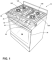
- reference numeral 10 generally designates a gas cooktop appliance.
- the gas cooktop appliance 10 includes a burner 12A, a gas supply circuit 14 in fluid communication with the burner 12A, and a valve 16A for controlling an amount of gas supplied to the burner 12A from the gas supply circuit 14.
- An electrode 18A is configured to provide an ignition spark 20 and to obtain an ionization current 22.
- a control system 100 is operably coupled with the valve 16A and is configured to compare the ionization current 22 to a setting of the valve 16A and modify the amount of gas supplied to the burner 12A when the difference between the ionization current 22 to the setting of the valve 16A is above a predetermined threshold.
- the gas cooktop appliance 10 may include a plurality of burners 12A-12D, each with a different electrode 18A-18D and valve 16A-16D.
- the gas supply circuit 14 may provide gas to each of the burners 12A-12D by operation of the valves 16A-16D.
- Each electrode 18A-18D and each valve 16A-16D may be electrically coupled to the control system 100 via an electric circuit 24.
- the control system 100 may be configured to change a setting of the valves 16A-16D and receive the ionization current 22 from the electrodes 18A-18D.
- the gas cooktop appliance 10 may include a user interface 26 that includes control knobs 28 (or other types of user inputs) for manually adjusting corresponding valves 16A-16D between settings.
- the settings include an off setting and a variable temperature setting for providing a variety of temperatures.
- the user interface 26 may also include buttons 30 (e.g., push buttons or touch buttons) that allow a user to input other operational parameters and preferences and a display 32 that shows operational status and user input.
- the gas cooktop appliance 10 may include an oven compartment 34 and a door 36 that provides access to the oven compartment 34.
- each of the burners 12B-12D may have the same configuration as the burner 12A.
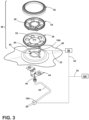
- the burner 12A may fluidically connect to the gas supply circuit 14 via a gas inlet 38 that supplies fuel to the burner 12A through an injector orifice 40 at a terminal end of the gas inlet 38.
- the injector orifice 40 may be secured in position below a cooktop aperture 42 with a bracket 44 that is fastened to an underside of a cooktop 46.
- a burner assembly 48 may include a burner base 50 defining a venturi opening 52, a swirl spreading disk 54 with a crenellated outer wall 56, and an annular burning cap 58.
- the annular burning cap 58 may direct gas and/or flame through the crenellated outer wall 56.
- the electrode 18A is positioned to provide the ignition spark 20 to the provided gas.
- the valve 16A may be coupled to the gas inlet 38 or anywhere along the gas supply circuit 14.
- Each valve 16A-16D may be configured as a control valve that receives instructions from the control system 100 and/or manually opens via the knobs 28.
- a translation module 60 e.g., a current-to-voltage converter circuit
- the translation module 60 may be singular or there may be a translation module 60 associated with each electrode 18A-18D (e.g., four).
- the translation module 60 is configured to receive the ionization current 22 from one of the electrodes 18A-18D and provide an analog voltage 62 to the control system 100.
- the translation module 60 may be hardware (e.g., an integrated circuit), executable instructions contained within the control system 100, or combinations thereof.
- the ionization current 22 and the analog voltage 62 may be directly proportional.
- the translation module 60 may provide an output of the analog voltage 62 within a range, for example, between 0 V and 5 V.
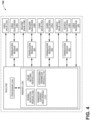
- the control system 100 of the gas cooktop appliance 10 may include at least one electronic control unit (ECU) 102.
- the at least one ECU 102 may include the processor 104 and a memory 106.
- the processor 104 may include any suitable processor 104. Additionally, or alternatively, each ECU 102 may include any suitable number of processors, in addition to or other than the processor 104.
- the memory 106 may comprise a single disk or a plurality of disks (e.g., hard drives) and includes a storage management module that manages one or more partitions within the memory 106.
- the memory 106 may include flash memory, semiconductor (solid state) memory, or the like.
- the memory 106 may include Random Access Memory (RAM), a Read-Only Memory (ROM), Electrically Erasable Programmable Read-Only Memory (EEPROM), or a combination thereof.
- the memory 106 may include instructions that, when executed by the processor 104, cause the processor 104 to, at least, perform the functions associated with the components of the gas cooktop appliance 10.
- a combination of components of the cooktop appliance 10, including one, more, or each of the valves 16A-16D, the electrodes 18A-18D, the user interface 26, and the translation module 60 may, therefore, be controlled by the control system 100.
- the memory 106 may, therefore, include a vessel detection module 108, a valve setting module 110, an ionization current heat profile 112, and operational parameter module 114.
- the control system 100 may be configured to receive the ionization current 22 from the electrodes 18A-18D and/or the analog voltage 62 from the translation module 60.
- FIG. 5 illustrates the analog voltage 62 from the translation module 60 with a series of valve settings corresponding to gas output. When the flame is on, air around the burner 12A is ionized causing change in the ionization current 22 and, therefore, also the analog voltage 62.
- the control system 100 may be configured to compare the ionization current 22 and/or the analog voltage 62 with the ionization current heat profile 112 to determine the presence of the flame and extrapolate a present flame output of the burner 12A by the magnitude of the ionization current 22 and/or the analog voltage 62.
- the ionization current heat profile 112 may include predictive models (e.g., temperature profiles) or other translational algorithms that, once the ionization current 22 and/or the analog voltage 62 is received, can be used to extrapolate the flame output.
- control system 100 e.g., the processor 104 may be configured to compare the present flame output of the burner 12A with the valve setting (e.g., via the valve setting module 110) to determine if the present flame output of the burner 12A corresponds to the expected flame output associated with the valve setting.
- the valves 16A-16D may include a plurality of settings that correspond to predicted models of expected flame output for those settings that are saved in the valve setting module 110.
- control system 100 may be configured to automatically modify the valve setting and/or generate a notification for a user to manually modify the valve setting upon a determination that the present flame output is different than the expected flame output by the predetermined threshold (e.g., 5% difference or greater, 10% difference or greater, 15% difference or greater, 20% difference or greater, 25% difference or greater, or 30% difference or greater). Accordingly, accuracy of the valve setting may be maintained over the operational life of the gas cooktop appliance 10 such that a user input to the valve setting results in the expected flame output.
- the valve setting module 110 may receive inputs from the user interface 26. For example, the valve setting module 110 may receive inputs based on a setting selected on an associated one of the knobs 28 or other types of heat setting user inputs (e.g., buttons that select a specific temperature or setting that may be graphically generated on the display 32).
- the analog voltage 62 is illustrated without a cooking vessel (e.g., a pan, pot, plate, and/or the like) on the burner 12A ( FIG. 6 ) and with the cooking vessel on the burner 12A ( FIG. 7 ).
- the ionization current 22 changes (i.e., and the analog voltage 62 likewise changes) as a result of the size of the flame but also as a result of a change to the shape of the flame.
- These changes follow predictive models (e.g., saved in the operational parameter module 114) that can be used to determine if a cooking vessel is located on the burner 12A or if the placement of the cooking vessel is correct.
- the control system 100 may be configured to determine if the cooking vessel is located on the burner 12A.
- the vessel detection module 108 may include instructions (e.g., profile data) for the processor 104 to compare with the ionization current 22 and/or the analog voltage 62 to determine the presence, absence, or incorrect (e.g., off-center) placement of the cooking vessel.
- the control system 100 e.g., the processor 104 may change the valve setting and/or generate a notification to a user based on the presence, absence, or incorrect placement of the cooking vessel.
- the control system 100 may be configured to modify the valve setting (e.g., to increase the present flame output).
- the gas cooktop appliance 10 may have an active cooking setting (e.g., selectable via the user interface 26 and/or as a standard operation principle of the cooktop appliance 10) that permits automatic modification of the valve setting.
- the control system 100 e.g., the processor 104 may be configured to modify the valve setting upon a determination of the absence of the cooking vessel.
- a predetermined amount of time without the presence of the cooking vessel may result in the valve setting being turned down to a non-zero setting or completely off.
- a predetermined amount of time without the presence of the cooking vessel may result in generating a notification to a user to adjust the valve setting or otherwise place the cooking vessel on the burner 12A.
- the control system 100 may be configured to, if the valve setting is on and the flame is detected a predetermined amount of time without the presence of the cooking vessel, first generate a notification to a user or turn the burner down.
- the first predetermined amount of time may be 10 seconds or more, 15 seconds or more, 20 seconds or more, 30 seconds or more, or 1 minute or less and the second predetermined threshold may be double the first predetermined threshold (e.g., after an additional 10 seconds or more, 15 seconds or more, 20 seconds or more, 30 seconds or more, or 1 minute or less).
- the control system 100 e.g., the processor 104 may be configured to determine that the cooking vessel is only partially located over the burner 12A (i.e., that the cooking vessel is incorrectly placed on the burner 12A). Upon determining incorrect placement of the cooking vessel, the control system 100 (e.g., the processor 104) may be configured to generate a notification to the user and/or adjust (e.g., reduce) the valve setting.
- the control system 100 may make determinations via communication signals from the valves 16A-16D, the electrodes 18A-18D, the user interface 26, and the translation module 60 as described herein.
- the determinations may include cooking vessel identification, accuracy of the valve settings, and other functions and methodologies described herein.
- the control system 100 may be configured to automatically adjust the valve settings or generate alerts to instruct the user to manually make changes to the valve settings.
- the alerts may be generated visually on the display 32 or audibly via the user interface 26 or another component.
- the control system 100 may generate an alert and automatically make changes to the valve setting, such that the alert simply notifies a user.
- a gas cooktop appliance includes a burner, a gas supply circuit in fluid communication with the burner, and a valve for controlling an amount of gas supplied to the burner from the gas supply circuit.
- An electrode is configured to provide an ignition spark and to obtain an ionization current.
- a control system is operably coupled with the valve and the electrode. The control system is configured to compare the ionization current to a setting of the valve and detect if a difference between the ionization current and the setting of the valve is outside a predetermined threshold. The control system is further configured to modify the amount of gas supplied to the burner until the difference is within the predetermined threshold.
- the ionization current is translated into an analog voltage by a translation module prior to being compared with the setting of the valve.
- control system is further configured to monitor the analog voltage and compare the analog voltage to a predictive model stored in a memory of the control system to determine a presence of a cooking vessel on the burner; or the control system is configured to monitor the ionization current and compare the ionization current to a predictive model stored in a memory of the control system to determine a presence of a cooking vessel on the burner.
- control system is further configured to, upon determining an absence of a cooking vessel for a first predetermined amount of time, reduce the setting of the valve.
- a seventh aspect according to aspect four or six after a second predetermined amount of time that is greater than the first predetermined amount of time the setting of the valve is turned to off.
- control system is further configured to, upon determining an absence of a cooking vessel for a first predetermined amount of time or for the first predetermined amount of time, generate a notification to a user.
- control system is further configured to generate the notification to the user audibly.
- the notification includes an alert for the user to manually reduce the setting of the valve.
- control system includes a memory and a processor
- the memory includes instructions that cause the processor to compare the analog voltage to a temperature profile of the setting of the valve.
- the translation module includes a current-to-voltage converter circuit.
- control system is further configured to: upon determining an absence of the cooking vessel for a first predetermined amount of time, generate a signal for a user to manually reduce the setting of the valve.
- control system is further configured to: upon determining an absence of the cooking vessel for a first predetermined amount of time, generate a signal to automatically reduce the setting of the valve.
- control system is further configured to: associate the predetermined threshold with a present flame output and an expected flame output.
- the predetermined threshold is a 5% difference or greater between the present flame output and the expected flame output.
- a gas cooktop appliance includes a burner, a gas supply circuit in fluid communication with the burner, and a valve for controlling an amount of gas supplied to the burner from the gas supply circuit.
- An electrode is configured to provide an ignition spark and to obtain an ionization current.
- a translation module is configured to translate the ionization current to an analog voltage.
- a control system is operably coupled with the valve and the translation module. The control system is configured to compare the analog voltage to a setting of the valve and to detect if a difference between the analog voltage and the setting of the valve is outside a predetermined threshold. The control system is further configured to modify the amount of gas supplied to the burner until the difference is within the predetermined threshold.
- the translation module includes a current-to-voltage converter circuit.
- control system is further configured to monitor an analog voltage and compare the analog voltage to a predictive model stored in a memory of the control system to determine a presence of a cooking vessel on a burner.
- control system is further configured to, upon determining an absence of a cooking vessel for a first predetermined amount of time, reduce a setting of a valve.
- the setting of the valve is reduced to a lower, non-zero setting.
- control system is further configured to, upon determining an absence of a cooking vessel for a first predetermined amount of time, generate a notification to a user.
- control system is further configured to generate the notification to the user audibly.
- a gas cooktop appliance includes a burner, a gas supply circuit in fluid communication with the burner, and a valve for controlling an amount of gas supplied to the burner from the gas supply circuit.
- An electrode is configured to provide an ignition spark and to obtain an ionization current.
- a control system is operably coupled with the valve and the electrode. The control system is configured to monitor the ionization current and compare the ionization current to a predictive model stored in a memory of the control system to determine a presence of a cooking vessel on the burner. The control system is further configured to, upon determining an absence of the cooking vessel for a first predetermined amount of time, generate a signal to reduce the setting of the valve.
- the signal includes an alert for a user to manually reduce the setting of the valve.
- the signal is transmitted to the valve to automatically reduce the setting of the valve.
- the term "coupled” in all of its forms, couple, coupling, coupled, etc. generally means the joining of two components (electrical or mechanical) directly or indirectly to one another. Such joining may be stationary in nature or movable in nature. Such joining may be achieved with the two components (electrical or mechanical) and any additional intermediate members being integrally formed as a single unitary body with one another or with the two components. Such joining may be permanent in nature or may be removable or releasable in nature unless otherwise stated.
- elements shown as integrally formed may be constructed of multiple parts or elements shown as multiple parts may be integrally formed, the operation of the interfaces may be reversed or otherwise varied, the length or width of the structures and/or members or connectors or other elements of the system may be varied, and the nature or number of adjustment positions provided between the elements may be varied.
- the elements and/or assemblies of the system may be constructed from any of a wide variety of materials that provide sufficient strength or durability, in any of a wide variety of colors, textures, and combinations. Accordingly, all such modifications are intended to be included within the scope of the present innovations. Other substitutions, modifications, changes, and omissions may be made in the design, operating conditions, and arrangement of the desired and other exemplary embodiments without departing from the spirit of the present innovations.
Landscapes
- Engineering & Computer Science (AREA)
- Chemical & Material Sciences (AREA)
- Combustion & Propulsion (AREA)
- Mechanical Engineering (AREA)
- General Engineering & Computer Science (AREA)
- Feeding And Controlling Fuel (AREA)
Abstract
Description
- The present disclosure generally relates to gas cooktop, and, more specifically, to a gas burner with an electrode that provides ignition of a gas and measures ionization current.
- According to one aspect of the present disclosure, a gas cooktop appliance includes a burner, a gas supply circuit in fluid communication with the burner, and a valve for controlling an amount of gas supplied to the burner from the gas supply circuit. An electrode is configured to provide an ignition spark and to obtain an ionization current. A control system is operably coupled with the valve and the electrode. The control system is configured to compare the ionization current to a setting of the valve and detect if a difference between the ionization current and the setting of the valve is outside a predetermined threshold. The control system is further configured to modify the amount of gas supplied to the burner until the difference is within the predetermined threshold.
- According to another aspect of the present disclosure, a gas cooktop appliance includes a burner, a gas supply circuit in fluid communication with the burner, and a valve for controlling an amount of gas supplied to the burner from the gas supply circuit. An electrode is configured to provide an ignition spark and to obtain an ionization current. A translation module is configured to translate the ionization current to an analog voltage. A control system is operably coupled with the valve and the translation module. The control system is configured to compare the analog voltage to a setting of the valve and detect if a difference between the analog voltage and the setting of the valve is outside a predetermined threshold. The control system is further configured to modify the amount of gas supplied to the burner until the difference is within the predetermined threshold.
- According to yet another aspect of the present disclosure, a gas cooktop appliance includes a burner, a gas supply circuit in fluid communication with the burner, and a valve for controlling an amount of gas supplied to the burner from the gas supply circuit. An electrode is configured to provide an ignition spark and to obtain an ionization current. A control system is operably coupled with the valve and the electrode. The control system is configured to monitor the ionization current and compare the ionization current to a predictive model stored in a memory of the control system to determine a presence of a cooking vessel on the burner. The control system to, upon determining an absence of the cooking vessel for a first predetermined amount of time, generate a signal to reduce the setting of the valve.
- These and other features, advantages, and objects of the present disclosure will be further understood and appreciated by those skilled in the art by reference to the following specification, claims, and appended drawings.
- In the drawings:
-
FIG. 1 is a front perspective view of a gas cooktop appliance, in accordance with an aspect of the present disclosure; -
FIG. 2 is a top schematic view of a gas cooktop appliance, in accordance with an aspect of the present disclosure; -
FIG. 3 is a disassembled top perspective view of a burner for a gas cooktop appliance, in accordance with an aspect of the present disclosure; -
FIG. 4 is a schematic view of a control system for a gas cooktop appliance, in accordance with an aspect of the present disclosure; -
FIG. 5 is a graphical representation of an analog voltage translated from an ionization current of a gas cooktop appliance between a series of gas flow settings, in accordance with an aspect of the present disclosure; -
FIG. 6 is a graphical representation of an analog voltage translated from an ionization current of a gas cooktop appliance between an on position and an off position without a cooking vessel, in accordance with an aspect of the present disclosure; and -
FIG. 7 is a graphical representation of an analog voltage translated from an ionization current of a gas cooktop appliance between an on position and an off position with a cooking vessel, in accordance with an aspect of the present disclosure. - The components in the figures are not necessarily to scale, emphasis instead being placed upon illustrating the principles described herein.
- The present illustrated embodiments reside primarily in combinations of method steps and apparatus components related to a gas burner with an electrode that provides ignition of a gas and measures ionization current. Accordingly, the apparatus components and method steps have been represented, where appropriate, by conventional symbols in the drawings, showing only those specific details that are pertinent to understanding the embodiments of the present disclosure so as not to obscure the disclosure with details that will be readily apparent to those of ordinary skill in the art having the benefit of the description herein. Further, like numerals in the description and drawings represent like elements.
- For purposes of description herein, the terms "upper," "lower," "right," "left," "rear," "front," "vertical," "horizontal," and derivatives thereof shall relate to the disclosure as oriented in
FIG. 1 . Unless stated otherwise, the term "front" shall refer to the surface of the element closer to an intended viewer, and the term "rear" shall refer to the surface of the element further from the intended viewer. However, it is to be understood that the disclosure may assume various alternative orientations, except where expressly specified to the contrary. It is also to be understood that the specific devices and processes illustrated in the attached drawings, and described in the following specification are simply exemplary embodiments of the inventive concepts defined in the appended claims. Hence, specific dimensions and other physical characteristics relating to the embodiments disclosed herein are not to be considered as limiting, unless the claims expressly state otherwise. - The terms "including," "comprises," "comprising," or any other variation thereof, are intended to cover a non-exclusive inclusion, such that a process, method, article, or apparatus that comprises a list of elements does not include only those elements but may include other elements not expressly listed or inherent to such process, method, article, or apparatus. An element preceded by "comprises a ..." does not, without more constraints, preclude the existence of additional identical elements in the process, method, article, or apparatus that comprises the element.
- Referring to
FIGS. 1-7 ,reference numeral 10 generally designates a gas cooktop appliance. Thegas cooktop appliance 10 includes aburner 12A, agas supply circuit 14 in fluid communication with theburner 12A, and avalve 16A for controlling an amount of gas supplied to theburner 12A from thegas supply circuit 14. Anelectrode 18A is configured to provide anignition spark 20 and to obtain anionization current 22. Acontrol system 100 is operably coupled with thevalve 16A and is configured to compare theionization current 22 to a setting of thevalve 16A and modify the amount of gas supplied to theburner 12A when the difference between theionization current 22 to the setting of thevalve 16A is above a predetermined threshold. - With reference now to
FIGS. 1 and2 , thegas cooktop appliance 10 may include a plurality ofburners 12A-12D, each with adifferent electrode 18A-18D andvalve 16A-16D. Thegas supply circuit 14 may provide gas to each of theburners 12A-12D by operation of thevalves 16A-16D. Eachelectrode 18A-18D and eachvalve 16A-16D may be electrically coupled to thecontrol system 100 via anelectric circuit 24. In this manner, thecontrol system 100 may be configured to change a setting of thevalves 16A-16D and receive theionization current 22 from theelectrodes 18A-18D. Thegas cooktop appliance 10 may include auser interface 26 that includes control knobs 28 (or other types of user inputs) for manually adjustingcorresponding valves 16A-16D between settings. The settings include an off setting and a variable temperature setting for providing a variety of temperatures. Theuser interface 26 may also include buttons 30 (e.g., push buttons or touch buttons) that allow a user to input other operational parameters and preferences and adisplay 32 that shows operational status and user input. Thegas cooktop appliance 10 may include anoven compartment 34 and adoor 36 that provides access to theoven compartment 34. - With reference now to
FIG. 3 , theburner 12A is illustrated in a disassembled condition. It should be appreciated that each of theburners 12B-12D may have the same configuration as theburner 12A. Theburner 12A may fluidically connect to thegas supply circuit 14 via agas inlet 38 that supplies fuel to theburner 12A through aninjector orifice 40 at a terminal end of thegas inlet 38. Theinjector orifice 40 may be secured in position below acooktop aperture 42 with abracket 44 that is fastened to an underside of acooktop 46. Aburner assembly 48 may include aburner base 50 defining aventuri opening 52, aswirl spreading disk 54 with a crenellatedouter wall 56, and anannular burning cap 58. The annularburning cap 58 may direct gas and/or flame through the crenellatedouter wall 56. Theelectrode 18A is positioned to provide theignition spark 20 to the provided gas. Thevalve 16A may be coupled to thegas inlet 38 or anywhere along thegas supply circuit 14. Eachvalve 16A-16D may be configured as a control valve that receives instructions from thecontrol system 100 and/or manually opens via theknobs 28. In some embodiments, a translation module 60 (e.g., a current-to-voltage converter circuit) is electrically located between each of theelectrodes 18A-18D and thecontrol system 100. Thetranslation module 60 may be singular or there may be atranslation module 60 associated with eachelectrode 18A-18D (e.g., four). Thetranslation module 60 is configured to receive theionization current 22 from one of theelectrodes 18A-18D and provide ananalog voltage 62 to thecontrol system 100. Thetranslation module 60 may be hardware (e.g., an integrated circuit), executable instructions contained within thecontrol system 100, or combinations thereof. The ionization current 22 and theanalog voltage 62 may be directly proportional. Thetranslation module 60 may provide an output of theanalog voltage 62 within a range, for example, between 0 V and 5 V. - With reference now to
FIG. 4 , thecontrol system 100 of thegas cooktop appliance 10 may include at least one electronic control unit (ECU) 102. The at least oneECU 102 may include theprocessor 104 and amemory 106. Theprocessor 104 may include anysuitable processor 104. Additionally, or alternatively, eachECU 102 may include any suitable number of processors, in addition to or other than theprocessor 104. Thememory 106 may comprise a single disk or a plurality of disks (e.g., hard drives) and includes a storage management module that manages one or more partitions within thememory 106. In some embodiments, thememory 106 may include flash memory, semiconductor (solid state) memory, or the like. Thememory 106 may include Random Access Memory (RAM), a Read-Only Memory (ROM), Electrically Erasable Programmable Read-Only Memory (EEPROM), or a combination thereof. Thememory 106 may include instructions that, when executed by theprocessor 104, cause theprocessor 104 to, at least, perform the functions associated with the components of thegas cooktop appliance 10. A combination of components of thecooktop appliance 10, including one, more, or each of thevalves 16A-16D, theelectrodes 18A-18D, theuser interface 26, and thetranslation module 60 may, therefore, be controlled by thecontrol system 100. Thememory 106 may, therefore, include avessel detection module 108, avalve setting module 110, an ionizationcurrent heat profile 112, andoperational parameter module 114. - With reference to
FIGS. 4-6 , the control system 100 (e.g., the processor 104) may be configured to receive the ionization current 22 from theelectrodes 18A-18D and/or theanalog voltage 62 from thetranslation module 60. For example,FIG. 5 illustrates theanalog voltage 62 from thetranslation module 60 with a series of valve settings corresponding to gas output. When the flame is on, air around theburner 12A is ionized causing change in the ionization current 22 and, therefore, also theanalog voltage 62. The control system 100 (e.g., the processor 104) may be configured to compare the ionization current 22 and/or theanalog voltage 62 with the ionizationcurrent heat profile 112 to determine the presence of the flame and extrapolate a present flame output of theburner 12A by the magnitude of the ionization current 22 and/or theanalog voltage 62. In other words, the ionizationcurrent heat profile 112 may include predictive models (e.g., temperature profiles) or other translational algorithms that, once the ionization current 22 and/or theanalog voltage 62 is received, can be used to extrapolate the flame output. In this manner, the control system 100 (e.g., the processor 104) may be configured to compare the present flame output of theburner 12A with the valve setting (e.g., via the valve setting module 110) to determine if the present flame output of theburner 12A corresponds to the expected flame output associated with the valve setting. More particularly, thevalves 16A-16D may include a plurality of settings that correspond to predicted models of expected flame output for those settings that are saved in thevalve setting module 110. - In some embodiments, the control system 100 (e.g., the processor 104) may be configured to automatically modify the valve setting and/or generate a notification for a user to manually modify the valve setting upon a determination that the present flame output is different than the expected flame output by the predetermined threshold (e.g., 5% difference or greater, 10% difference or greater, 15% difference or greater, 20% difference or greater, 25% difference or greater, or 30% difference or greater). Accordingly, accuracy of the valve setting may be maintained over the operational life of the
gas cooktop appliance 10 such that a user input to the valve setting results in the expected flame output. Thevalve setting module 110 may receive inputs from theuser interface 26. For example, thevalve setting module 110 may receive inputs based on a setting selected on an associated one of theknobs 28 or other types of heat setting user inputs (e.g., buttons that select a specific temperature or setting that may be graphically generated on the display 32). - With reference now to
FIGS. 6 and 7 , theanalog voltage 62 is illustrated without a cooking vessel (e.g., a pan, pot, plate, and/or the like) on theburner 12A (FIG. 6 ) and with the cooking vessel on theburner 12A (FIG. 7 ). The ionization current 22 changes (i.e., and theanalog voltage 62 likewise changes) as a result of the size of the flame but also as a result of a change to the shape of the flame. These changes follow predictive models (e.g., saved in the operational parameter module 114) that can be used to determine if a cooking vessel is located on theburner 12A or if the placement of the cooking vessel is correct. Therefore, as a cooking vessel is placed on theburner 12A, the ionization current 22 and theanalog voltage 62 change. In this manner, the control system 100 (e.g., the processor 104) may be configured to determine if the cooking vessel is located on theburner 12A. For example, thevessel detection module 108 may include instructions (e.g., profile data) for theprocessor 104 to compare with the ionization current 22 and/or theanalog voltage 62 to determine the presence, absence, or incorrect (e.g., off-center) placement of the cooking vessel. In this manner, the control system 100 (e.g., the processor 104) may change the valve setting and/or generate a notification to a user based on the presence, absence, or incorrect placement of the cooking vessel. - For example, upon a determination of the presence of the cooking vessel, the control system 100 (e.g., the processor 104) may be configured to modify the valve setting (e.g., to increase the present flame output). In some embodiments, the
gas cooktop appliance 10 may have an active cooking setting (e.g., selectable via theuser interface 26 and/or as a standard operation principle of the cooktop appliance 10) that permits automatic modification of the valve setting. In some embodiments, upon a determination of the absence of the cooking vessel, the control system 100 (e.g., the processor 104) may be configured to modify the valve setting. For example, if the valve setting is on and the flame is detected, a predetermined amount of time without the presence of the cooking vessel may result in the valve setting being turned down to a non-zero setting or completely off. In some embodiments, if the valve setting is on and the flame is detected, a predetermined amount of time without the presence of the cooking vessel may result in generating a notification to a user to adjust the valve setting or otherwise place the cooking vessel on theburner 12A. In some embodiments, thecontrol system 100 may be configured to, if the valve setting is on and the flame is detected a predetermined amount of time without the presence of the cooking vessel, first generate a notification to a user or turn the burner down. Then after a second predetermined amount of time that is longer than the first predetermined amount of time, completely turn the valve off so that gas is no longer supplied to theburner 12A. The first predetermined amount of time may be 10 seconds or more, 15 seconds or more, 20 seconds or more, 30 seconds or more, or 1 minute or less and the second predetermined threshold may be double the first predetermined threshold (e.g., after an additional 10 seconds or more, 15 seconds or more, 20 seconds or more, 30 seconds or more, or 1 minute or less). In some embodiments, the control system 100 (e.g., the processor 104) may be configured to determine that the cooking vessel is only partially located over theburner 12A (i.e., that the cooking vessel is incorrectly placed on theburner 12A). Upon determining incorrect placement of the cooking vessel, the control system 100 (e.g., the processor 104) may be configured to generate a notification to the user and/or adjust (e.g., reduce) the valve setting. - With reference now to
FIGS. 1-7 , it should be appreciated that thecontrol system 100 may make determinations via communication signals from thevalves 16A-16D, theelectrodes 18A-18D, theuser interface 26, and thetranslation module 60 as described herein. The determinations may include cooking vessel identification, accuracy of the valve settings, and other functions and methodologies described herein. Once the determination is made, thecontrol system 100 may be configured to automatically adjust the valve settings or generate alerts to instruct the user to manually make changes to the valve settings. The alerts may be generated visually on thedisplay 32 or audibly via theuser interface 26 or another component. In some embodiments, thecontrol system 100 may generate an alert and automatically make changes to the valve setting, such that the alert simply notifies a user. - The disclosure herein is further summarized in the following paragraphs and is further characterized by combinations of any and all of the various aspects described therein.
- According to a first aspect of the present disclosure, a gas cooktop appliance includes a burner, a gas supply circuit in fluid communication with the burner, and a valve for controlling an amount of gas supplied to the burner from the gas supply circuit. An electrode is configured to provide an ignition spark and to obtain an ionization current. A control system is operably coupled with the valve and the electrode. The control system is configured to compare the ionization current to a setting of the valve and detect if a difference between the ionization current and the setting of the valve is outside a predetermined threshold. The control system is further configured to modify the amount of gas supplied to the burner until the difference is within the predetermined threshold.
- In a second aspect according to aspect one, the ionization current is translated into an analog voltage by a translation module prior to being compared with the setting of the valve.
- In a third aspect according to aspect two, the control system is further configured to monitor the analog voltage and compare the analog voltage to a predictive model stored in a memory of the control system to determine a presence of a cooking vessel on the burner; or the control system is configured to monitor the ionization current and compare the ionization current to a predictive model stored in a memory of the control system to determine a presence of a cooking vessel on the burner.
- In a fourth aspect according to aspect three, the control system is further configured to, upon determining an absence of a cooking vessel for a first predetermined amount of time, reduce the setting of the valve.
- In a fifth aspect according to aspect four, after the first predetermined amount of time, the setting of a valve is reduced to off.
- In a sixth aspect according to aspect four, after the first predetermined amount of time, the setting of a valve is reduced to a lower, non-zero setting.
- In a seventh aspect according to aspect four or six, after a second predetermined amount of time that is greater than the first predetermined amount of time the setting of the valve is turned to off.
- In an eighth aspect according to any of aspects three to seven, the control system is further configured to, upon determining an absence of a cooking vessel for a first predetermined amount of time or for the first predetermined amount of time, generate a notification to a user.
- In a ninth aspect according to aspect eight, the control system is further configured to generate the notification to the user audibly.
- In a tenth aspect according to aspect eight or nine, the notification includes an alert for the user to manually reduce the setting of the valve.
- In an eleventh aspect according to any one of aspects two to ten, the control system includes a memory and a processor, the memory includes instructions that cause the processor to compare the analog voltage to a temperature profile of the setting of the valve.
- In a twelfth aspect according to any one of aspects two to eleven, the translation module includes a current-to-voltage converter circuit.
- In a thirteenth aspect according to any one of aspects one to three, the control system is further configured to: upon determining an absence of the cooking vessel for a first predetermined amount of time, generate a signal for a user to manually reduce the setting of the valve.
- In a fourteenth aspect according to any one of aspects one to three, the control system is further configured to: upon determining an absence of the cooking vessel for a first predetermined amount of time, generate a signal to automatically reduce the setting of the valve.
- In a fifteenth aspect according to any one of aspects one to fourteen, the control system is further configured to: associate the predetermined threshold with a present flame output and an expected flame output.
- In a sixteenth aspect according to aspect fifteen, the predetermined threshold is a 5% difference or greater between the present flame output and the expected flame output.
- According to a seventeenth aspect of the present disclosure, a gas cooktop appliance includes a burner, a gas supply circuit in fluid communication with the burner, and a valve for controlling an amount of gas supplied to the burner from the gas supply circuit. An electrode is configured to provide an ignition spark and to obtain an ionization current. A translation module is configured to translate the ionization current to an analog voltage. A control system is operably coupled with the valve and the translation module. The control system is configured to compare the analog voltage to a setting of the valve and to detect if a difference between the analog voltage and the setting of the valve is outside a predetermined threshold. The control system is further configured to modify the amount of gas supplied to the burner until the difference is within the predetermined threshold.
- In an eighteenth aspect according to aspect seventeen, the translation module includes a current-to-voltage converter circuit.
- In a nineteenth aspect according to aspect seventeen or eighteen, the control system is further configured to monitor an analog voltage and compare the analog voltage to a predictive model stored in a memory of the control system to determine a presence of a cooking vessel on a burner.
- In a twentieth aspect according to aspect nineteen, the control system is further configured to, upon determining an absence of a cooking vessel for a first predetermined amount of time, reduce a setting of a valve.
- In a twenty-first aspect according to aspect twenty, after the first predetermined amount of time, the setting of the valve is reduced to a lower, non-zero setting.
- In a twenty-second aspect according to aspect twenty or twenty-one, after a second predetermined amount of time that is greater than the first predetermined amount of time, the setting of the valve is turned to off.
- In a twenty-third aspect according to aspect nineteen, the control system is further configured to, upon determining an absence of a cooking vessel for a first predetermined amount of time, generate a notification to a user.
- In a twenty-fourth aspect according to aspect twenty-three, the control system is further configured to generate the notification to the user audibly.
- According to twenty-fifth aspect of the present disclosure, a gas cooktop appliance includes a burner, a gas supply circuit in fluid communication with the burner, and a valve for controlling an amount of gas supplied to the burner from the gas supply circuit. An electrode is configured to provide an ignition spark and to obtain an ionization current. A control system is operably coupled with the valve and the electrode. The control system is configured to monitor the ionization current and compare the ionization current to a predictive model stored in a memory of the control system to determine a presence of a cooking vessel on the burner. The control system is further configured to, upon determining an absence of the cooking vessel for a first predetermined amount of time, generate a signal to reduce the setting of the valve.
- In a twenty-sixth aspect according to aspect twenty-five, the signal includes an alert for a user to manually reduce the setting of the valve.
- In a twenty-seventh aspect according to aspect twenty-five or twenty-six, the signal is transmitted to the valve to automatically reduce the setting of the valve.
- It will be understood by one having ordinary skill in the art that construction of the described disclosure and other components is not limited to any specific material. Other exemplary embodiments of the disclosure disclosed herein may be formed from a wide variety of materials, unless described otherwise herein.
- For purposes of this disclosure, the term "coupled" (in all of its forms, couple, coupling, coupled, etc.) generally means the joining of two components (electrical or mechanical) directly or indirectly to one another. Such joining may be stationary in nature or movable in nature. Such joining may be achieved with the two components (electrical or mechanical) and any additional intermediate members being integrally formed as a single unitary body with one another or with the two components. Such joining may be permanent in nature or may be removable or releasable in nature unless otherwise stated.
- It is also important to note that the construction and arrangement of the elements of the disclosure as shown in the exemplary embodiments is illustrative only. Although only a few embodiments of the present innovations have been described in detail in this disclosure, those skilled in the art who review this disclosure will readily appreciate that many modifications are possible (e.g., variations in sizes, dimensions, structures, shapes and proportions of the various elements, values of parameters, mounting arrangements, use of materials, colors, orientations, etc.) without materially departing from the novel teachings and advantages of the subject matter recited. For example, elements shown as integrally formed may be constructed of multiple parts or elements shown as multiple parts may be integrally formed, the operation of the interfaces may be reversed or otherwise varied, the length or width of the structures and/or members or connectors or other elements of the system may be varied, and the nature or number of adjustment positions provided between the elements may be varied. It should be noted that the elements and/or assemblies of the system may be constructed from any of a wide variety of materials that provide sufficient strength or durability, in any of a wide variety of colors, textures, and combinations. Accordingly, all such modifications are intended to be included within the scope of the present innovations. Other substitutions, modifications, changes, and omissions may be made in the design, operating conditions, and arrangement of the desired and other exemplary embodiments without departing from the spirit of the present innovations.
- It will be understood that any described processes or steps within described processes may be combined with other disclosed processes or steps to form structures within the scope of the present disclosure. The exemplary structures and processes disclosed herein are for illustrative purposes and are not to be construed as limiting.
Claims (15)
- A gas cooktop appliance (10) comprising:a burner (12A, 12B, 12C, 12D);a gas supply circuit (14) in fluid communication with the burner (12A, 12B, 12C, 12D);a valve (16A, 16B, 16C, 16d) for controlling an amount of gas supplied to the burner (12A, 12B, 12C, 12D) from the gas supply circuit;an electrode (18A, 18B, 18C, 18D) configured to provide an ignition spark (20) and to obtain an ionization current (22); anda control system (100) is operably coupled with the valve and the electrode, the control system (100) is configured to:compare the ionization current (22) to a setting of the valve (16A, 16B, 16C, 16D);detect if a difference between the ionization current (22) and the setting of the valve (16A, 16B, 16C, 16D) is outside a predetermined threshold; andmodify the amount of gas supplied to the burner (12A, 12B, 12C, 12D) until the difference is within the predetermined threshold.
- The gas cooktop appliance (10) of claim 1, wherein the ionization current (22) is translated into an analog voltage (62) by a translation module (60) prior to being compared with the setting of the valve (16A, 16B, 16C, 16D).
- The gas cooktop appliance (10) of claim 2, wherein the control system (100) is further configured to monitor the analog voltage (62) and compare the analog voltage (62) to a predictive model stored in a memory (106) of the control system (100) to determine a presence of a cooking vessel on the burner (12A, 12B, 12C, 12D).
- The gas cooktop appliance (10) of claim 3, wherein the control system (100) is further configured to, upon determining an absence of the cooking vessel for a first predetermined amount of time, reduce the setting of the valve (16A, 16B, 16C, 16D).
- The gas cooktop appliance (10) of claim 4, wherein after the first predetermined amount of time, the setting of the valve (16A, 16B, 16C, 16D) is reduced to off.
- The gas cooktop appliance (10) of claim 4, wherein after the first predetermined amount of time, the setting of the valve (16A, 16B, 16C, 16D) is reduced to a lower, non-zero setting.
- The gas cooktop appliance (10) of claim 6, wherein after a second predetermined amount of time that is greater than the first predetermined amount of time, the setting of the valve (16A, 16B, 16C, 16D) is turned to off.
- The gas cooktop appliance (10) of any one of claims 3-7, wherein the control system (100) is further configured to, upon determining an absence of the cooking vessel for a first predetermined amount of time, generate a notification to a user.
- The gas cooktop appliance (10) of claim 8, wherein the control system (100) is further configured to generate the notification to a user audibly.
- The gas cooktop appliance (10) of claim 8, wherein the notification includes an alert for a user to manually reduce the setting of the valve (16A, 16B, 16C, 16D).
- The gas cooktop appliance (10) of any one of claims 4-10, wherein the control system (100) includes a memory (106) and a processor (104), the memory (106) including instructions that cause the processor (104) to compare the analog voltage (62) to a temperature profile of the setting of the valve (16A, 16B, 16C, 16D).
- The gas cooktop appliance (10) of any one of claims 1-11, wherein the translation module (60) includes a current-to-voltage converter circuit (60).
- The gas cooktop appliance (10) of claim 1, wherein the control system (100) is further configured to:
upon determining an absence of the cooking vessel for a first predetermined amount of time, generate a signal for a user to manually reduce the setting of the valve (16A, 16B, 16C, 16D). - The gas cooktop appliance (10) of claim 1, wherein the control system (100) is further configured to:
upon determining an absence of the cooking vessel for a first predetermined amount of time, generate a signal to automatically reduce the setting of the valve (16A, 16B, 16C, 16D). - The gas cooktop appliance (10) of claim 1, wherein the control system (100) is further configured to:
associate the predetermined threshold with a present flame output and an expected flame output, the predetermined threshold being a 5% difference or greater between the present flame output and the expected flame output.
Applications Claiming Priority (2)
| Application Number | Priority Date | Filing Date | Title |
|---|---|---|---|
| US202263387378P | 2022-12-14 | 2022-12-14 | |
| US18/506,271 US20240200783A1 (en) | 2022-12-14 | 2023-11-10 | Flame ionization detection for pan detection and power management in a gas cooktop |
Publications (1)
| Publication Number | Publication Date |
|---|---|
| EP4386265A1 true EP4386265A1 (en) | 2024-06-19 |
Family
ID=89222290
Family Applications (1)
| Application Number | Title | Priority Date | Filing Date |
|---|---|---|---|
| EP23216164.6A Withdrawn EP4386265A1 (en) | 2022-12-14 | 2023-12-13 | Gas cooktop appliance |
Country Status (2)
| Country | Link |
|---|---|
| US (1) | US20240200783A1 (en) |
| EP (1) | EP4386265A1 (en) |
Citations (6)
| Publication number | Priority date | Publication date | Assignee | Title |
|---|---|---|---|---|
| JPH08215039A (en) * | 1994-12-23 | 1996-08-27 | Diehl Gmbh & Co | Cookware with glass ceramic cooking surface |
| US6322352B1 (en) * | 1998-06-10 | 2001-11-27 | Isphording Germany Gmbh | Gas burner system |
| DE10217008B4 (en) * | 2002-04-16 | 2006-04-06 | Miele & Cie. Kg | Method for operating a gas-fired cooking or roasting device and device for carrying out the method |
| US20120276487A1 (en) * | 2011-03-03 | 2012-11-01 | Siemens Aktiengesellschaft | Burner system |
| ITTO20110776A1 (en) * | 2011-08-25 | 2013-02-26 | Indesit Co Spa | GAS COOKING APPLIANCE WITH SAFETY |
| US9909763B2 (en) * | 2014-09-18 | 2018-03-06 | E.G.O. Elektro-Geraetebau Gmbh | Method of pot detection and gas hob |
-
2023
- 2023-11-10 US US18/506,271 patent/US20240200783A1/en active Pending
- 2023-12-13 EP EP23216164.6A patent/EP4386265A1/en not_active Withdrawn
Patent Citations (6)
| Publication number | Priority date | Publication date | Assignee | Title |
|---|---|---|---|---|
| JPH08215039A (en) * | 1994-12-23 | 1996-08-27 | Diehl Gmbh & Co | Cookware with glass ceramic cooking surface |
| US6322352B1 (en) * | 1998-06-10 | 2001-11-27 | Isphording Germany Gmbh | Gas burner system |
| DE10217008B4 (en) * | 2002-04-16 | 2006-04-06 | Miele & Cie. Kg | Method for operating a gas-fired cooking or roasting device and device for carrying out the method |
| US20120276487A1 (en) * | 2011-03-03 | 2012-11-01 | Siemens Aktiengesellschaft | Burner system |
| ITTO20110776A1 (en) * | 2011-08-25 | 2013-02-26 | Indesit Co Spa | GAS COOKING APPLIANCE WITH SAFETY |
| US9909763B2 (en) * | 2014-09-18 | 2018-03-06 | E.G.O. Elektro-Geraetebau Gmbh | Method of pot detection and gas hob |
Also Published As
| Publication number | Publication date |
|---|---|
| US20240200783A1 (en) | 2024-06-20 |
Similar Documents
| Publication | Publication Date | Title |
|---|---|---|
| EP2327932B1 (en) | Method of operating a smart gas burner system for cooking appliance | |
| US7231917B2 (en) | Gas-fired cooking apparatus with control of cooking temperature | |
| US8469019B2 (en) | Method and apparatus for providing ultra low gas burner performance for a cooking appliance | |
| EP3098517B1 (en) | Burner assembly | |
| US10928062B2 (en) | Cooking device and method for controlling the same | |
| US20080110999A1 (en) | Setting Oven/Grill Temperature and/or Meat Probe Using Stepper Motor Analog Display | |
| KR101529116B1 (en) | An apparatus of controlling overheating protection of gas cooktop for extending life of its battery and the method thereof | |
| US20240200783A1 (en) | Flame ionization detection for pan detection and power management in a gas cooktop | |
| EP3098518B1 (en) | Cooking device | |
| US20200271314A1 (en) | Gas burner, gas burner assembly and domestic cooking appliance | |
| US20200217504A1 (en) | Method of operating an oven appliance based on fuel type | |
| KR102307945B1 (en) | Gas Range | |
| US11892173B2 (en) | Intelligent gas cooktop burner | |
| JP6706087B2 (en) | Cooker | |
| CN206324681U (en) | A kind of gas oven | |
| KR20140091288A (en) | A cooking appliance | |
| US11513551B2 (en) | Cooking appliance and knob assembly for preventing accidental engagement | |
| US20250146671A1 (en) | Electric heating assembly and prevention of moisture-induced failure | |
| JP2022191631A (en) | Cooker | |
| EP0340032A2 (en) | Gas cooking appliances | |
| JP2659324B2 (en) | Cooking equipment | |
| JP3745115B2 (en) | Cooker | |
| JP2659323B2 (en) | Cooking equipment | |
| KR100541115B1 (en) | Microwave Toaster & Control Method | |
| KR950007400B1 (en) | Cooking equipment |
Legal Events
| Date | Code | Title | Description |
|---|---|---|---|
| PUAI | Public reference made under article 153(3) epc to a published international application that has entered the european phase |
Free format text: ORIGINAL CODE: 0009012 |
|
| STAA | Information on the status of an ep patent application or granted ep patent |
Free format text: STATUS: THE APPLICATION HAS BEEN PUBLISHED |
|
| AK | Designated contracting states |
Kind code of ref document: A1 Designated state(s): AL AT BE BG CH CY CZ DE DK EE ES FI FR GB GR HR HU IE IS IT LI LT LU LV MC ME MK MT NL NO PL PT RO RS SE SI SK SM TR |
|
| RAP1 | Party data changed (applicant data changed or rights of an application transferred) |
Owner name: BEKO EUROPE MANAGEMENT S.R.L. |
|
| P01 | Opt-out of the competence of the unified patent court (upc) registered |
Free format text: CASE NUMBER: APP_59209/2024 Effective date: 20241030 |
|
| STAA | Information on the status of an ep patent application or granted ep patent |
Free format text: STATUS: REQUEST FOR EXAMINATION WAS MADE |
|
| 17P | Request for examination filed |
Effective date: 20241205 |
|
| STAA | Information on the status of an ep patent application or granted ep patent |
Free format text: STATUS: EXAMINATION IS IN PROGRESS |
|
| 17Q | First examination report despatched |
Effective date: 20250807 |
|
| STAA | Information on the status of an ep patent application or granted ep patent |
Free format text: STATUS: THE APPLICATION IS DEEMED TO BE WITHDRAWN |
|
| 18D | Application deemed to be withdrawn |
Effective date: 20251209 |