EP4386259A1 - Vertical type once-through heat recovery steam generator and combined power generation system including same - Google Patents
Vertical type once-through heat recovery steam generator and combined power generation system including same Download PDFInfo
- Publication number
- EP4386259A1 EP4386259A1 EP23190143.0A EP23190143A EP4386259A1 EP 4386259 A1 EP4386259 A1 EP 4386259A1 EP 23190143 A EP23190143 A EP 23190143A EP 4386259 A1 EP4386259 A1 EP 4386259A1
- Authority
- EP
- European Patent Office
- Prior art keywords
- pressure
- medium
- steam
- feedwater
- desuperheater
- Prior art date
- Legal status (The legal status is an assumption and is not a legal conclusion. Google has not performed a legal analysis and makes no representation as to the accuracy of the status listed.)
- Granted
Links
Images


Classifications
-
- F—MECHANICAL ENGINEERING; LIGHTING; HEATING; WEAPONS; BLASTING
- F22—STEAM GENERATION
- F22B—METHODS OF STEAM GENERATION; STEAM BOILERS
- F22B29/00—Steam boilers of forced-flow type
- F22B29/06—Steam boilers of forced-flow type of once-through type, i.e. built-up from tubes receiving water at one end and delivering superheated steam at the other end of the tubes
-
- F—MECHANICAL ENGINEERING; LIGHTING; HEATING; WEAPONS; BLASTING
- F01—MACHINES OR ENGINES IN GENERAL; ENGINE PLANTS IN GENERAL; STEAM ENGINES
- F01K—STEAM ENGINE PLANTS; STEAM ACCUMULATORS; ENGINE PLANTS NOT OTHERWISE PROVIDED FOR; ENGINES USING SPECIAL WORKING FLUIDS OR CYCLES
- F01K23/00—Plants characterised by more than one engine delivering power external to the plant, the engines being driven by different fluids
- F01K23/02—Plants characterised by more than one engine delivering power external to the plant, the engines being driven by different fluids the engine cycles being thermally coupled
- F01K23/06—Plants characterised by more than one engine delivering power external to the plant, the engines being driven by different fluids the engine cycles being thermally coupled combustion heat from one cycle heating the fluid in another cycle
- F01K23/10—Plants characterised by more than one engine delivering power external to the plant, the engines being driven by different fluids the engine cycles being thermally coupled combustion heat from one cycle heating the fluid in another cycle with exhaust fluid of one cycle heating the fluid in another cycle
- F01K23/106—Plants characterised by more than one engine delivering power external to the plant, the engines being driven by different fluids the engine cycles being thermally coupled combustion heat from one cycle heating the fluid in another cycle with exhaust fluid of one cycle heating the fluid in another cycle with water evaporated or preheated at different pressures in exhaust boiler
-
- F—MECHANICAL ENGINEERING; LIGHTING; HEATING; WEAPONS; BLASTING
- F22—STEAM GENERATION
- F22B—METHODS OF STEAM GENERATION; STEAM BOILERS
- F22B1/00—Methods of steam generation characterised by form of heating method
- F22B1/02—Methods of steam generation characterised by form of heating method by exploitation of the heat content of hot heat carriers
- F22B1/18—Methods of steam generation characterised by form of heating method by exploitation of the heat content of hot heat carriers the heat carrier being a hot gas, e.g. waste gas such as exhaust gas of internal-combustion engines
- F22B1/1861—Waste heat boilers with supplementary firing
-
- F—MECHANICAL ENGINEERING; LIGHTING; HEATING; WEAPONS; BLASTING
- F02—COMBUSTION ENGINES; HOT-GAS OR COMBUSTION-PRODUCT ENGINE PLANTS
- F02C—GAS-TURBINE PLANTS; AIR INTAKES FOR JET-PROPULSION PLANTS; CONTROLLING FUEL SUPPLY IN AIR-BREATHING JET-PROPULSION PLANTS
- F02C7/00—Features, components parts, details or accessories, not provided for in, or of interest apart form groups F02C1/00 - F02C6/00; Air intakes for jet-propulsion plants
- F02C7/12—Cooling of plants
- F02C7/14—Cooling of plants of fluids in the plant, e.g. lubricant or fuel
- F02C7/141—Cooling of plants of fluids in the plant, e.g. lubricant or fuel of working fluid
-
- F—MECHANICAL ENGINEERING; LIGHTING; HEATING; WEAPONS; BLASTING
- F02—COMBUSTION ENGINES; HOT-GAS OR COMBUSTION-PRODUCT ENGINE PLANTS
- F02C—GAS-TURBINE PLANTS; AIR INTAKES FOR JET-PROPULSION PLANTS; CONTROLLING FUEL SUPPLY IN AIR-BREATHING JET-PROPULSION PLANTS
- F02C7/00—Features, components parts, details or accessories, not provided for in, or of interest apart form groups F02C1/00 - F02C6/00; Air intakes for jet-propulsion plants
- F02C7/22—Fuel supply systems
- F02C7/224—Heating fuel before feeding to the burner
-
- F—MECHANICAL ENGINEERING; LIGHTING; HEATING; WEAPONS; BLASTING
- F22—STEAM GENERATION
- F22B—METHODS OF STEAM GENERATION; STEAM BOILERS
- F22B1/00—Methods of steam generation characterised by form of heating method
- F22B1/02—Methods of steam generation characterised by form of heating method by exploitation of the heat content of hot heat carriers
- F22B1/18—Methods of steam generation characterised by form of heating method by exploitation of the heat content of hot heat carriers the heat carrier being a hot gas, e.g. waste gas such as exhaust gas of internal-combustion engines
- F22B1/1807—Methods of steam generation characterised by form of heating method by exploitation of the heat content of hot heat carriers the heat carrier being a hot gas, e.g. waste gas such as exhaust gas of internal-combustion engines using the exhaust gases of combustion engines
- F22B1/1815—Methods of steam generation characterised by form of heating method by exploitation of the heat content of hot heat carriers the heat carrier being a hot gas, e.g. waste gas such as exhaust gas of internal-combustion engines using the exhaust gases of combustion engines using the exhaust gases of gas-turbines
-
- F—MECHANICAL ENGINEERING; LIGHTING; HEATING; WEAPONS; BLASTING
- F22—STEAM GENERATION
- F22B—METHODS OF STEAM GENERATION; STEAM BOILERS
- F22B11/00—Steam boilers of combined fire-tube type and water-tube type, i.e. steam boilers of fire-tube type having auxiliary water tubes
- F22B11/02—Steam boilers of combined fire-tube type and water-tube type, i.e. steam boilers of fire-tube type having auxiliary water tubes the fire tubes being in upright arrangement
-
- F—MECHANICAL ENGINEERING; LIGHTING; HEATING; WEAPONS; BLASTING
- F22—STEAM GENERATION
- F22B—METHODS OF STEAM GENERATION; STEAM BOILERS
- F22B37/00—Component parts or details of steam boilers
- F22B37/02—Component parts or details of steam boilers applicable to more than one kind or type of steam boiler
- F22B37/42—Applications, arrangements or dispositions of alarm or automatic safety devices
- F22B37/47—Applications, arrangements or dispositions of alarm or automatic safety devices responsive to abnormal temperature, e.g. actuated by fusible plugs
-
- F—MECHANICAL ENGINEERING; LIGHTING; HEATING; WEAPONS; BLASTING
- F22—STEAM GENERATION
- F22G—SUPERHEATING OF STEAM
- F22G1/00—Steam superheating characterised by heating method
- F22G1/02—Steam superheating characterised by heating method with heat supply by hot flue gases from the furnace of the steam boiler
-
- Y—GENERAL TAGGING OF NEW TECHNOLOGICAL DEVELOPMENTS; GENERAL TAGGING OF CROSS-SECTIONAL TECHNOLOGIES SPANNING OVER SEVERAL SECTIONS OF THE IPC; TECHNICAL SUBJECTS COVERED BY FORMER USPC CROSS-REFERENCE ART COLLECTIONS [XRACs] AND DIGESTS
- Y02—TECHNOLOGIES OR APPLICATIONS FOR MITIGATION OR ADAPTATION AGAINST CLIMATE CHANGE
- Y02E—REDUCTION OF GREENHOUSE GAS [GHG] EMISSIONS, RELATED TO ENERGY GENERATION, TRANSMISSION OR DISTRIBUTION
- Y02E20/00—Combustion technologies with mitigation potential
- Y02E20/16—Combined cycle power plant [CCPP], or combined cycle gas turbine [CCGT]
Definitions
- the present disclosure relates to a vertical type once-through heat recovery steam generator (HRSG) capable of improving operational stability during rapid startup and lifetime of a steam turbine while reducing environmental pollution caused by emissions, and a combined power generation system including the same.
- HRSG vertical type once-through heat recovery steam generator
- a combined power generation system is a power generation system in which primary and secondary power generation facilities are combined.
- a combined power generation system operates such that fuel is combusted inside a gas turbine to produce high-temperature combustion gases, which rotate the gas turbine to generate primary power, and a steam turbine is driven to generate secondary power with high-temperature and high-pressure steam generated by using heat of exhaust gases discharged from the primary power generation process.
- This combined power generation system has advantages including highly efficient energy utilization and a short time of startup for power generation.
- the highly efficient energy utilization is achieved by usage of combustion heat of fuel, which is primarily utilized in a gas turbine, and is recycled in a heat recovery steam generator (HRSG).
- HRSG heat recovery steam generator
- the short time for power generation is achieved by the HRSG system's rapid startup process from startup to power generation.
- the combined power generation system can use clean fuel, which is eco-friendly than other fuels.
- HRSG is a type of heat exchanger.
- HRSGs may be broadly categorized into horizontal and vertical types depending on a flow direction of exhaust gases.
- the horizontal type has the configuration in which exhaust gases flow in a horizontal direction
- the vertical type has the configuration in which exhaust gases flow in a vertical direction.
- the vertical type HRSG has the advantage of a smaller installation area compared to the horizontal type.
- HRSGs may be broadly categorized into a natural circulation type and a forced circulation type depending on the circulation method utilized in HRSGs.
- the natural circulation type is a type in which circulation is performed by density difference
- the forced circulation type is a type in which circulation of water or steam inside the HRSG is performed by a separately equipped circulation pump.
- an objective of the present disclosure is to provide a vertical type once-through heat recovery steam generator (HRSG) and a combined power generation system including the same, which is capable of improving operational stability during rapid startup and lifetime of a steam turbine while reducing environmental pollution caused by emissions.
- HRSG heat recovery steam generator
- a vertical type once-through heat recovery steam generator including: a low-pressure section including a condensate preheater configured to heat feedwater through heat exchange with combustion gases and supply the heated feedwater to a low-pressure drum, a low-pressure evaporator configured to heat feedwater stored in the low-pressure drum and convert the feedwater to steam, and a low-pressure superheater configured to heat the steam separated from the feedwater in the low-pressure drum and supply the heated steam to a low-pressure steam turbine; a medium-pressure section including a medium-pressure economizer configured to receive a portion of the feedwater heated by the condensate preheater, heat the feedwater through heat exchange with combustion gases, and supply the heated feedwater to a medium-pressure drum, a medium-pressure evaporator configured to heat the feedwater stored in the medium-pressure drum and convert the heated feedwater to steam, a medium-pressure superheater configured to heat the steam separated from the feedwater in the medium
- HRSG vertical type once-through heat recovery steam generator
- the low-pressure section may include a condensate preheater bypass configured to allow a portion of the feedwater to bypass the condensate preheater and flow to the low-pressure drum.
- the medium-pressure section may include a first medium-pressure reheater, a first medium-pressure desuperheater, a second medium-pressure reheater, and a second medium-pressure desuperheater sequentially between the medium-pressure superheater and the medium-pressure steam turbine such that the steam heated in the medium-pressure superheater is supplied to the medium-pressure steam turbine through the first medium-pressure reheater, the first medium-pressure desuperheater, the second medium-pressure reheater, and the second medium-pressure desuperheater, wherein the first and second desuperheaters form the medium-pressure side desuperheater.
- a feedwater line between the medium-pressure drum and the medium-pressure superheater may be supplied with steam heated by an external heater.
- the external heater may be configured to generate steam through heat exchange of a portion of the feedwater with high-temperature compressed air compressed from a compressor of a gas turbine and supply the generated steam to the feedwater line.
- the high-pressure superheater may include first and second high-pressure superheaters and the high-pressure side desuperheater may include first high-pressure desuperheater and second high-pressure desuperheater, wherein the first high-pressure superheater, the first high-pressure desuperheater, the second high-pressure superheater, and the second high-pressure desuperheater are disposed sequentially between the multi-stage once-through evaporator and the high-pressure steam turbine such that the steam heated in the multi-stage once-through evaporator is supplied to the high-pressure steam turbine through the first high-pressure superheater, the first high-pressure desuperheater, the second high-pressure superheater, and the second high-pressure desuperheater.
- a steam separator may be disposed between the multi-stage once-through evaporator and the first high-pressure superheater to separate steam contained in the feedwater having flowed through the multi-stage once-through evaporator.
- a portion of the feedwater heated in the high-pressure economizer may be supplied to a fuel preheater of a combustor through a fuel-preheating feedwater line.
- the multi-stage once-through evaporator may include: an inlet part which receives feedwater; and a heat transfer tube having a front end connected to the inlet part and a rear end out of which steam is discharged such that the feedwater from the inlet part is evaporated through heat exchange with the combustion gases while flowing from the front end to the rear end, wherein the heat transfer tube may be formed such that an inner diameter of the rear end is larger than that of the front end.
- the heat transfer tube may include a plurality of heat transfer tube parts having different inner diameters each increasing stepwise toward the rear end of the heat transfer tube.
- a combined power generation system including: a gas turbine including a compressor configured to suck and compress external air, a combustor configured to mix fuel with the compressed air and combust the mixture, and a turbine rotated by combustion gases discharged from the combustor to generate a rotational force; a heat recovery steam generator (HRSG) configured to heat feedwater and generate steam by using combustion gases discharged from the gas turbine; and a steam turbine in which blades are rotated by the steam generated from the HRSG to generate a rotational force.
- a gas turbine including a compressor configured to suck and compress external air, a combustor configured to mix fuel with the compressed air and combust the mixture, and a turbine rotated by combustion gases discharged from the combustor to generate a rotational force
- HRSG heat recovery steam generator
- the HRSG may include: a low-pressure section including a condensate preheater configured to heat feedwater through heat exchange with combustion gases and supply the heated feedwater to a low-pressure drum, a low-pressure evaporator configured to heat feedwater stored in the low-pressure drum and convert the feedwater to steam, and a low-pressure superheater configured to heat the steam separated from the feedwater in the low-pressure drum and supply the heated steam to a low-pressure steam turbine; a medium-pressure section including a medium-pressure economizer configured to receive a portion of the feedwater heated by the condensate preheater, heat the feedwater through heat exchange with combustion gases, and supply the heated feedwater to a medium-pressure drum, a medium-pressure evaporator configured to heat the feedwater stored in the medium-pressure drum and convert the heated feedwater to steam, a medium-pressure superheater configured to heat the steam separated from the feedwater in the medium-pressure drum and supply the heated steam to a medium-pressure steam turbine, and a
- the low-pressure section may include a condensate preheater bypass configured to allow a portion of the feedwater to bypass the condensate preheater and flow directly to the low-pressure drum.
- the medium-pressure section may include a first medium-pressure reheater, a first medium-pressure desuperheater, a second medium-pressure reheater, and a second medium-pressure desuperheater sequentially between the medium-pressure superheater and the medium-pressure steam turbine such that the steam heated in the medium-pressure superheater is supplied to the medium-pressure steam turbine through the first medium-pressure reheater, the first medium-pressure desuperheater, the second medium-pressure reheater, and the second medium-pressure desuperheater, consecutively.
- a feedwater line between the medium-pressure drum and the medium-pressure superheater may be supplied with steam heated by an external heater.
- the external heater may be configured to generate steam through heat exchange of a portion of the feedwater with high-temperature compressed air compressed from a compressor of a gas turbine and supply the generated steam to the feedwater line.
- the high-pressure superheater may include first and second high-pressure superheaters and the high-pressure side desuperheater may include first high-pressure desuperheater and second high-pressure desuperheater, wherein the first high-pressure superheater, the first high-pressure desuperheater, the second high-pressure superheater, and the second high-pressure desuperheater are disposed sequentially between the multi-stage once-through evaporator and the high-pressure steam turbine such that the steam heated in the multi-stage once-through evaporator is supplied to the high-pressure steam turbine through the first high-pressure superheater, the first high-pressure desuperheater, the second high-pressure superheater, and the second high-pressure desuperheater.
- a steam separator may be disposed between the multi-stage once-through evaporator and the first high-pressure superheater to separate steam contained in the feedwater having flowed through the multi-stage once-through evaporator.
- a portion of the feedwater heated in the high-pressure economizer may be supplied to a fuel preheater of a combustor through a fuel-preheating feedwater line.
- the multi-stage once-through evaporator may include: an inlet part which receives feedwater; and a heat transfer tube having a front end connected to the inlet part and a rear end out of which steam is discharged such that the feedwater from the inlet part is evaporated through heat exchange with combustion gases while flowing from the front end to the rear end, wherein the heat transfer tube may be formed such that an inner diameter of the rear end is larger than that of the front end.
- the heat transfer tube may include a plurality of heat transfer tube parts having different inner diameters each increasing stepwise toward the rear end of the heat transfer tube.
- FIG, 1 is a diagram illustrating a combined power generation system according to an embodiment of the present disclosure.
- the combined power generation system 100 may include a gas turbine 110, a steam turbine 120, a generator 130, and a heat recovery steam generator (HRSG) 1000.
- the steam turbine 120 may include a low-pressure steam turbine 120a, a medium-pressure steam turbine 120b, and a high-pressure steam turbine 120c.
- the gas turbine 110 may serve to suck atmospheric air, compress the air to a high-pressure, burn an air-fuel mixture in static pressure conditions to release thermal energy, expand high-temperature combustion gases for conversion into kinetic energy, and then discharge exhaust gases containing the residual energy to the atmosphere.
- the gas turbine 110 may include a compressor 111, a combustor 112, and a turbine section 113.
- the compressor 111 of the gas turbine 110 may suck and compress external air.
- the compressor 111 may serve both to supply the compressed air generated by compressor blades to the combustor 112 and to supply the cooling air to a high temperature region of the gas turbine 110.
- the air passing through the compressor 111 increases in pressure and temperature.
- the compressor 111 is usually designed as a centrifugal compressor or an axial compressor, wherein the centrifugal compressor is applied to a small-scale gas turbine, whereas a multi-stage axial compressor is applied to a large-scale gas turbine.
- the combustor 112 may mix compressed air supplied from an outlet of the compressor 111 with fuel and combust the air-fuel mixture at a constant pressure to produce high-energy combustion gases.
- a fuel preheater 112a receives fuel from a fuel supply via a fuel supply pipe, heats the fuel, and supplies the heated fuel to the combustor 112.
- the combustion gases undergo adiabatic expansion and impact and drive a plurality of blades arranged radially around a rotary shaft of the turbine section 113 so that heat energy of the combustion gases is converted into mechanical energy with which the rotary shaft is rotated.
- a portion of the mechanical energy obtained from the turbine section 113 is supplied as the energy required to compress the air in the compressor 111, and the rest is utilized as an available energy to drive the generator 130 to produce electric power.
- the combustion gases discharged from the turbine section 113 is cooled through the HRSG 1000 and then discharged to the outside.
- the HRSG 1000 serves to not only cool the combustion gases, but also generate high-temperature and high-pressure steam using the heat of the combustion gases and deliver same to the steam turbine 120.
- the steam generated in the HRSG 1000 is transmitted to the steam turbine 120 through a steam feed line L1, and feedwater cooled in the steam turbine 120 is transmitted to the HRSG 1000 through a turbine feedwater recovery line L2.
- the steam turbine 120 rotates blades using the steam generated by the HRSG 1000 and transmits the rotational energy to the generator 130.
- the steam turbine 120 supplies the cooled steam back to the HRSG 1000.
- gas turbine 110 and the steam turbine 120 are exemplified in FIG. 1 as being connected to one generator 130, the present disclosure is not limited thereto. Rather, the gas turbine 110 and the steam turbine 120 may be disposed in parallel and/or connected to different generators.
- the turbine feedwater recovery line L2 is connected with a condenser 121 for condensing steam, a condensate storage tank 122 for storing condensed feedwater, and a condensate pump 123 for supplying the condensed feedwater stored in the condensate storage tank 122 to the HRSG 1000.
- the steam flowing in the HRSG 1000 may have at least two or three levels of pressure, and accordingly, the feedwater is pressurized to at least two or three pressure levels.
- the HRSG 1000 is exemplified as having three levels of pressure.
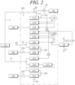
- FIG. 2 is a diagram illustrating a vertical type once-through heat recovery steam generator (HRSG) according to an embodiment of the present disclosure.
- the HRSG 1000 may include a low-pressure section 1100 having a relatively low-pressure, a medium-pressure section 1200 having a medium-pressure, and a high-pressure section 1300 having a relatively high-pressure.
- the high-pressure section 1300 may be disposed adjacent to an inlet side of the HRSG, through which combustion gases are introduced, and may be heated by high-temperature combustion gases
- the low-pressure section 1100 may be disposed adjacent to an outlet side of the HRSG, through which the combustion gases are discharged, and may be heated by low-temperature combustion gases.
- the low-pressure section 1100 may be disposed vertically upward than the high-pressure section 1300.
- the low-pressure section 1100 includes a condensate preheater 1110, a low-pressure drum 1120, a low-pressure evaporator 1130, a low-pressure superheater 1140, and a condensate preheater bypass 1150.
- the condensate stored in the condensate storage tank 122 is transferred to the condensate preheater 1110 by a condensate pump 123, and the condensate preheater 1110 heats the condensate through heat exchange with combustion gases.
- the feedwater heated in the condensate preheater 1110 is supplied to the low-pressure drum 1120.
- the low-pressure evaporator 1130 is connected to the low-pressure drum 1120 to heat the feedwater stored in the low-pressure drum 1120.
- the steam separated in the low-pressure drum 1120 is heated in the low-pressure superheater 1140, and then supplied to the low-pressure steam turbine 120a.
- the condensate preheater bypass 1150 allows a portion of the condensate transferred from the condensate storage tank 122 bypass the condensate preheater 1110 and to flow directly to the low-pressure drum 1120.
- the bypassing portion of the condensate may be diverted from a pipe between the condensate pump 123 and the condensate preheater 1110 to a pipe between the condensate preheater 1110 and the low-pressure drum 1120.
- the medium-pressure section 1200 includes a medium-pressure economizer 1210, a medium-pressure drum 1220, a medium-pressure evaporator 1230, a medium-pressure superheater 1240, a first reheater 1251, a second reheater 1252, a first desuperheater 1261, and a second desuperheater 1262.
- the medium-pressure section may further include a low-temperature reheating steam line L6 that reheats low-temperature steam discharged from the steam turbine 120.
- the first reheater 1251, a second reheater 1252, a first desuperheater 1261, and a second desuperheater 1262 of the medium-pressure section 1200 may be referred to as the first medium-pressure reheater 1251, a second medium-pressure reheater 1252, a first medium-pressure desuperheater 1261, and a second medium-pressure desuperheater 1262.
- a portion of feedwater heated by the condensate preheater 1110, and/or a portion of the condensate that bypassed the condensate preheater 1110 through the condensate preheater bypass 1150 is supplied, by and through the medium-pressure pump P1, to the medium-pressure economizer 1210.
- the medium-pressure economizer 1210 heats the feedwater or condensate supplied from the medium-pressure pump P1 (hereinafter collectively referred to as "feedwater”) through heat exchange with combustion gases.
- feedwater heated in the medium-pressure economizer 1210 is supplied to the medium-pressure drum 1220.
- the medium-pressure evaporator 1230 is connected to the medium-pressure drum 1220 to heat the feedwater stored in the medium-pressure drum 1220. Specifically, the medium-pressure evaporator 1230 receives the feedwater from the medium-pressure drum 1220, heat the feedwater through heat exchange with combustion gases, and returns the heated feedwater to the medium-pressure drum 1220. The heated steam is separated from the medium-pressure drum 1220 and then heated in the medium-pressure superheater 1240. Then, the heated steam is supplied to the medium-pressure steam turbine 120b.
- the heated steam may pass through the first reheater 1251, the first desuperheater 1261, and the second reheater 1252, consecutively.
- the first reheater 1251, the first desuperheater 1261, and the second reheater 1252 regulate and adjust the temperature of the steam entering the medium-pressure steam turbine 120b.
- reheated steam from the medium-pressure superheater 1240 may be joined by the low-temperature reheating steam line L6, which reheats the low-temperature steam discharged from the steam turbine 120.
- a second desuperheater 1262 is additionally installed to reduce and adjust the temperature of the steam entering the medium-pressure steam turbine 120b from the second reheater 1252 during rapid startup.
- the second desuperheater 1262 is installed between the second reheater 1252 and the medium-pressure steam turbine 120b.
- the second desuperheater 1262 may not need to operate continuously throughout the entire operation of the HRSG, instead, it may be activated solely during rapid startup, and subsequently turned off after the rapid startup process is completed.
- the feedwater line L3 between the medium-pressure drum 1220 and the medium-pressure superheater 1240 may be joined by steam heated by an external heater 124.
- the external heater 124 allows to generate steam through heat exchange of a portion of the feedwater supplied provided from the medium-pressure pump P1 using high-temperature compressed air compressed by the compressor 111, and the thereby generated steam is supplied to the feedwater line L3.
- the compressed air heat-exchanged in the external heater 124 is cooled to low temperature and returned to the gas turbine 110 to cool at least one of the compressor 111 and the turbine section 113.
- the external heater 124 may also functions as an external cooler for the gas turbine 110.
- the high-pressure section 1300 includes a high-pressure economizer 1310, a multi-stage once-through evaporator 1330, a high-pressure superheater 1340 (1341, 1342), a first desuperheater 1361, and a second desuperheater 1362.
- the first desuperheater 1361 and the second desuperheater 1362 of the high-pressure section 1300 may be referred to as the first high-pressure desuperheater 1361, and the second high-pressure desuperheater 1362.
- a portion of feedwater heated by the condensate preheater 1110, and/or a portion of the condensate that bypassed the condensate preheater 1110 through the condensate preheater bypass 1150 is supplied, by and through a high-pressure pump P2, to the high-pressure economizer 1310, which heats the feedwater through heat exchange with combustion gases.
- the high-pressure economizer 1310 may be formed in multiple stages to heat the feedwater sequentially.
- the feedwater heated by the high-pressure economizer 1310 is supplied to the multi-stage once-through evaporator 1330.
- the multi-stage once-through evaporator 1330 includes an inlet part 1331 into which feedwater flows in, and a heat transfer tube 1332 having a front end connected to the inlet part and a rear end out of which steam is discharged such that the feedwater from the inlet part 1331 is evaporated through heat exchange with combustion gases while flowing from the front end to the rear end.
- the heat transfer tube 1332 is formed such that an inner diameter of the rear end is larger than that of the front end. According to an embodiment, the heat transfer tube 1332 may be formed such that the inner diameter gradually increases from the front end toward the rear end.
- Such a multi-stage once-through evaporator 1330 may prevent static instability or Ledinegg instability caused by two-phase flow.
- the multi-stage once-through evaporator 1330 will described below furthermore in detail with reference to FIGS. 4 through 6 .
- Steam heated by the multi-stage once-through evaporator 1330 is supplied to the high-pressure steam turbine 120c through the first high-pressure superheater 1341, the first desuperheater 1361, and the second high-pressure superheater 1342, consecutively.
- the first high-pressure superheater 1341, the first desuperheater 1361, and the second high-pressure superheater 1342 regulate and adjust the temperature of the steam entering the high-pressure steam turbine 120c.
- a second desuperheater 1362 may be additionally installed to reduce the temperature of the steam entering the high-pressure steam turbine 120c during rapid startup.
- the second desuperheater 1362 is installed between the second high-pressure superheater 1342 and the high-pressure steam turbine 120c.
- the second desuperheater 1362 may not need to operate continuously throughout the entire operation of the HRSG, instead, it may be activated solely during rapid startup, and subsequently turned off after the rapid startup process is completed.
- the multi-stage once-through evaporator 1330 may not convert all of the incoming feedwater to steam immediately. Instead, at the beginning of the rapid startup, only a portion of the feedwater may be converted to steam, while the remaining portion may still exist in a liquid form. Therefore, a steam separator 1370 may be installed at the rear end of the multi-stage once-through evaporator 1330 and before the first high-pressure superheater 1341 for steam-water separation at the beginning of the rapid startup.
- the feedwater that has flowed through the multi-stage once-through evaporator 1330 may flow through the steam separator 1370 and, after that, into the first high-pressure superheater 1341.
- the steam separator 1370 may function only as a connection channel between the multi-stage once-through evaporator 1330 and the first high-pressure superheater 1341.
- a portion of the feedwater heated in the high-pressure economizer 1310 may be supplied to the fuel preheater 112a of the combustor 112 via the fuel preheating feedwater line L4.
- the high-temperature feedwater supplied to the fuel preheater 112a may be converted to cold feedwater after heating fuel through a heat exchange process, and returned to the condensate preheater 1110 through a return line L5.
- the second desuperheater 1262 of the medium-pressure section 1200 and the second desuperheater 1362 of the high-pressure section 1300 serve to prevent a rapid temperature increase during rapid startup. This not only enhances operational reliability but also help protect the lifetime of the steam turbine from being reduced.
- FIG. 3 is a diagram illustrating the HRSG according to the embodiment of the present disclosure.
- the feedwater supplied to the medium-pressure economizer 1210 and the feedwater supplied to the high-pressure economizer 1310 are illustrated as being supplied from the front end of the low-pressure drum 1120 (in other words, from condensate preheater 1110 without the feedwater being entering the lower-pressure drum 1120) by and through the medium-pressure pump P1 or high-pressure pump P2, respectively.
- the feedwater supplied to the medium-pressure economizer 1210 and the feedwater supplied to the high-pressure economizer 1310 may be supplied from the rear end of the low-pressure drum 1120 (in other words, after the feedwater passing through the low-pressure drum 1120) to the medium-pressure economizer 1210 or the high-pressure economizer 1310, respectively and through by the medium-pressure pump P1 or high-pressure pump P2.
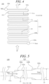
- FIG. 4 is a diagram illustrating a multi-stage once-through evaporator according to an embodiment of the present disclosure
- FIG. 5 is an enlarged cross-sectional view of the multi-stage once-through evaporator of FIG. 4
- FIG. 6 is a diagram illustrating a variant of the multi-stage once-through evaporator.
- the multi-stage once-through evaporator 1330 includes an inlet part 1331 and a heat transfer tube 1332, wherein the inlet part 1331 includes a small-diameter tube portion 1331a.
- the inlet part 1331 is in a form of a tube through which feedwater is introduced from the high-pressure economizer 1310.
- An inlet header 1330a may be disposed at the inlet part 1331, which has an inner diameter (D-in).
- the small-diameter tube portion 1331a may be a slender tube, an inner diameter of which may be the same with the inner diameter (D-in) of the inlet part.
- the pressure characteristic curve of the multi-stage once-through evaporator 1330 may change, which may improve flow instability within the multi-stage once-through evaporator 1330.
- the heat transfer tube 1332 is a tube having a front end connected to the rear end of the inlet part 1331 and a rear end out of which steam is discharged.
- An outlet header 1330b may be disposed at the rear end of the heat transfer tube 1332.
- the front end of the heating tube 1332 is supplied with feedwater from the inlet part 1331, and the feedwater is evaporated by heat exchange with a flow of combustion gases stream MF while flowing to the rear end of the heat transfer tube 1332 and then discharged.
- the heat transfer tube 1332 may be formed such that the inner diameter of the rear end is larger than that of the front end.
- the inlet-side inner diameter D-in which is the inner diameter of the small-diameter tube portion 1331a, may be configured to be smaller than the inner diameter of the heat transfer tube 1332.
- the inlet-side inner diameter D-in of the small-diameter tube portion 1331a of the inlet part 1331 may be smaller than the inner diameter of the front end of the heat transfer tube 1332, which in turn may be smaller than the inner diameter of the rear end of the heat transfer tube 1332.
- the heat transfer tube 1332 may include a plurality of heat transfer parts having different inner diameters, each of which may be formed to increase stepwise from the front end of the heat transfer tube 1332 to the rear end of the heat transfer tube 1332.
- the heat transfer tube 1332 may include a first heat transfer tube part 1332a and a second heat transfer tube part 1332b.
- the first heat transfer tube part 1332a is a heat transfer tube that has a first inner diameter D1 and whose front end is connected to the rear end of the inlet part 1331.
- the first inner diameter D1 is formed to be larger than the inlet-side inner diameter D-in.
- the second heat transfer tube part 1332b is a heat transfer tube that has a second inner diameter D2 and whose front end is connected to the rear end of the first heat transfer tuber part 1332a.
- the second inner diameter D2 is formed to be larger than the first inner diameter D1. That is, the inner diameter of the multi-stage once-through evaporator 1330 may progressively increase in sequential steps from the inlet part 1331 to the first heat transfer tube part 1332a, and further to the second heat transfer tube part 1332b.
- a tapered part 1333 may be disposed between the small-diameter tube portion 1331a and the first heat transfer tube part 1332a, and between the first heat transfer tube part 1332a and the second heat transfer tube part 1332b.
- a first tapered part 1333a may be disposed between the small-diameter tube portion 1331a and the first heat transfer tube part 1332a
- a second tapered part 1333b may be disposed between the first heat transfer tube part 1332a and the second heat transfer tube part 1332b.
- the tapered part 1333 has an inner diameter that increases gradually and gently toward a rear end thereof.
- tapered part 1333 helps prevent a sudden and discontinuous increase in the inner diameter, which in turn prevents flow delamination and improve flow stability within the multi-stage once-through evaporator 1330.
- the tapered part 1333 may be formed in the form of a straight line or a rounded curve when viewed in its cross-section.
- the heat transfer tube 1332 may further include a third heat transfer tube part 1332c.
- the third heat transfer tube part 1332c is a heat transfer tube having a front end connected to a rear end of the second heat transfer tube part 1332b and whose inner diameter is a third inner diameter D3.
- the third inner diameter D3 is formed to be larger than the second inner diameter D2.
- the inner diameter of the multi-stage once-through evaporator 1330 may progressively increase in sequential steps from the inlet part 1331 to the first heat transfer tube part 1332a and the second heat transfer tube part 133b and further to the third heat transfer tube part 1332c.
- the heat transfer tube 1332 may include four or more heat transfer tube parts, each having a sequentially increasing inner diameter toward the rear end thereof.
- a heat transfer tube part disposed more rearward has a diameter larger than the one disposed more forward.
- a pressure difference between the flow at the front end and the flow at the rear end of the multi-stage once-through evaporator 1330 This is referred to as a 'system pressure drop' or 'internal pressure drop'.
- the system pressure drop varies with a mass flow rate (i.e., a mass velocity - W).
- a mass flow rate i.e., a mass velocity - W.
- water evaporates inside the multi-stage once-through evaporator 1330 a two-phase flow phenomenon may occur where water and steam flow together.
- the change in pressure drop of steam, which is a gas phase is greater than the change in pressure drop of water, which is a liquid phase.
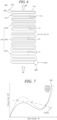
- the system pressure drop curve is formed to have a ridge and a valley where the slope varies from positive to negative value and then to a positive value (see the thin solid line in FIG. 7 ) as the mass flow rate increases.
- a flow rate in the multi-stage once-through evaporator 1330 is determined by a pressure drop curve of the evaporator outer head.
- the outer head is the head that provides a flow driving force, which may be determined by a height difference between the inlet header 1330a and the outlet header 1330b, or by a circulation pump or the like (see dashed line A in FIG. 7 ). More specifically, a flow rate in the multi-stage once-through evaporator 1330 is determined at the intersection between the system pressure drop curve and the pressure drop curve of the outer head.
- a flow rate in the multi-stage once-through evaporator 1330 may be determined at any of the intersections 1 to 3. If a plurality of multi-stage once-through evaporators 1330 are arranged in parallel, a flow rate in the multi-stage once-through evaporators 1330 may be arbitrarily determined at any one of the intersection points of 1 to 3, rather than determined at a specified one intersection.
- a mass flow rate different from an initially designed flow rate may flow in the multi-stage once-through evaporator 1330.
- This flow instability is referred to as static instability (or Ledinegg instability). If a flow rate is less than an initially designed flow rate, a problem may arise in that steam may overheat excessively at the rear end of the multi-stage once-through evaporator 1330.
- the multi-stage once-through evaporator 1330 may have a more gentle system pressure drop curve because the heat transfer tube 1332 is formed such that the inner diameter of the rear end is larger than that of the front end (see the bold solid line in FIG. 7 ). In this case, only one intersection (intersection 1) is formed between the system pressure drop curve and the pressure drop curve of the outer head, which may prevent static instability. Furthermore, as the inlet part 1331 includes the small-diameter tube portion 1331a, the system pressure drop curve is formed more gently so that the static instability phenomenon can be more reliably prevented.
Landscapes
- Engineering & Computer Science (AREA)
- Chemical & Material Sciences (AREA)
- Combustion & Propulsion (AREA)
- Mechanical Engineering (AREA)
- General Engineering & Computer Science (AREA)
- Physics & Mathematics (AREA)
- Thermal Sciences (AREA)
- Life Sciences & Earth Sciences (AREA)
- Sustainable Development (AREA)
- Sustainable Energy (AREA)
- Engine Equipment That Uses Special Cycles (AREA)
Abstract
Description
- The present application claims priority to
Korean Patent Application No. 10-2022-0176209, filed on DEC 15, 2022 - The present disclosure relates to a vertical type once-through heat recovery steam generator (HRSG) capable of improving operational stability during rapid startup and lifetime of a steam turbine while reducing environmental pollution caused by emissions, and a combined power generation system including the same.
- A combined power generation system is a power generation system in which primary and secondary power generation facilities are combined. In general, a combined power generation system operates such that fuel is combusted inside a gas turbine to produce high-temperature combustion gases, which rotate the gas turbine to generate primary power, and a steam turbine is driven to generate secondary power with high-temperature and high-pressure steam generated by using heat of exhaust gases discharged from the primary power generation process.
- This combined power generation system has advantages including highly efficient energy utilization and a short time of startup for power generation. The highly efficient energy utilization is achieved by usage of combustion heat of fuel, which is primarily utilized in a gas turbine, and is recycled in a heat recovery steam generator (HRSG). The short time for power generation is achieved by the HRSG system's rapid startup process from startup to power generation. In addition, the combined power generation system can use clean fuel, which is eco-friendly than other fuels.
- The heat of exhaust gases that produce high-temperature, high-pressure steam may be recovered by the HRSG. HRSG is a type of heat exchanger.
- HRSGs may be broadly categorized into horizontal and vertical types depending on a flow direction of exhaust gases. The horizontal type has the configuration in which exhaust gases flow in a horizontal direction, while the vertical type has the configuration in which exhaust gases flow in a vertical direction. The vertical type HRSG has the advantage of a smaller installation area compared to the horizontal type.
- Meanwhile, HRSGs may be broadly categorized into a natural circulation type and a forced circulation type depending on the circulation method utilized in HRSGs. The natural circulation type is a type in which circulation is performed by density difference, and the forced circulation type is a type in which circulation of water or steam inside the HRSG is performed by a separately equipped circulation pump.
- On the other hand, when the combined power generation system is started rapidly, an amount of steam generated by the HRSG increases rapidly during the start-up. However, rapidly increase in steam can lead to unstable operation and reduced overall power generation efficiency in the combined power generation system. In addition, there is another problem that a large amount of white smoke is generated due to the difference between the temperature of exhaust gases at an outlet of the HRSG and the ambient temperature.
- The foregoing is intended merely to aid in the understanding of the background of the present disclosure, and is not intended to mean that the present disclosure falls within the purview of the related art that is already known to those skilled in the art.
- Accordingly, the present disclosure has been made keeping in mind the above problems occurring in the related art, and an objective of the present disclosure is to provide a vertical type once-through heat recovery steam generator (HRSG) and a combined power generation system including the same, which is capable of improving operational stability during rapid startup and lifetime of a steam turbine while reducing environmental pollution caused by emissions.
- In an aspect of the present disclosure, there is provided a vertical type once-through heat recovery steam generator (HRSG) including: a low-pressure section including a condensate preheater configured to heat feedwater through heat exchange with combustion gases and supply the heated feedwater to a low-pressure drum, a low-pressure evaporator configured to heat feedwater stored in the low-pressure drum and convert the feedwater to steam, and a low-pressure superheater configured to heat the steam separated from the feedwater in the low-pressure drum and supply the heated steam to a low-pressure steam turbine; a medium-pressure section including a medium-pressure economizer configured to receive a portion of the feedwater heated by the condensate preheater, heat the feedwater through heat exchange with combustion gases, and supply the heated feedwater to a medium-pressure drum, a medium-pressure evaporator configured to heat the feedwater stored in the medium-pressure drum and convert the heated feedwater to steam, a medium-pressure superheater configured to heat the steam separated from the feedwater in the medium-pressure drum and supply the heated steam to a medium-pressure steam turbine, and a medium-pressure side desuperheater installed at the rear of the medium-pressure superheater to lower the temperature of the steam supplied to a medium-pressure steam turbine; and a high-pressure section including a high-pressure economizer configured to receive a portion of the feedwater heated by the condensate preheater and heat the feedwater through heat exchange with combustion gases, a multi-stage once-through evaporator configured to heat the feedwater heated by the high-pressure economizer through heat exchange with the combustion gases, a high-pressure superheater configured to heat the steam heated by the multi-stage once-through evaporator and supply the heated steam to a high-pressure steam turbine, and a high-pressure side desuperheater installed at the rear of the high-pressure superheater to lower the temperature of the steam supplied to the high-pressure steam turbine.
- In the vertical type once-through HRSG according to an embodiment of the present disclosure, the low-pressure section may include a condensate preheater bypass configured to allow a portion of the feedwater to bypass the condensate preheater and flow to the low-pressure drum.
- In the vertical type once-through HRSG according to an embodiment of the present disclosure, the medium-pressure section may include a first medium-pressure reheater, a first medium-pressure desuperheater, a second medium-pressure reheater, and a second medium-pressure desuperheater sequentially between the medium-pressure superheater and the medium-pressure steam turbine such that the steam heated in the medium-pressure superheater is supplied to the medium-pressure steam turbine through the first medium-pressure reheater, the first medium-pressure desuperheater, the second medium-pressure reheater, and the second medium-pressure desuperheater, wherein the first and second desuperheaters form the medium-pressure side desuperheater.
- In the vertical type once-through HRSG according to an embodiment of the present disclosure, a feedwater line between the medium-pressure drum and the medium-pressure superheater may be supplied with steam heated by an external heater. Here, the external heater may be configured to generate steam through heat exchange of a portion of the feedwater with high-temperature compressed air compressed from a compressor of a gas turbine and supply the generated steam to the feedwater line.
- In the vertical type once-through HRSG according to an embodiment of the present disclosure, the high-pressure superheater may include first and second high-pressure superheaters and the high-pressure side desuperheater may include first high-pressure desuperheater and second high-pressure desuperheater, wherein the first high-pressure superheater, the first high-pressure desuperheater, the second high-pressure superheater, and the second high-pressure desuperheater are disposed sequentially between the multi-stage once-through evaporator and the high-pressure steam turbine such that the steam heated in the multi-stage once-through evaporator is supplied to the high-pressure steam turbine through the first high-pressure superheater, the first high-pressure desuperheater, the second high-pressure superheater, and the second high-pressure desuperheater.
- In the vertical type once-through HRSG according to an embodiment of the present disclosure, a steam separator may be disposed between the multi-stage once-through evaporator and the first high-pressure superheater to separate steam contained in the feedwater having flowed through the multi-stage once-through evaporator.
- In the vertical type once-through HRSG according to an embodiment of the present disclosure, a portion of the feedwater heated in the high-pressure economizer may be supplied to a fuel preheater of a combustor through a fuel-preheating feedwater line.
- In the vertical type once-through HRSG according to an embodiment of the present disclosure, the multi-stage once-through evaporator may include: an inlet part which receives feedwater; and a heat transfer tube having a front end connected to the inlet part and a rear end out of which steam is discharged such that the feedwater from the inlet part is evaporated through heat exchange with the combustion gases while flowing from the front end to the rear end, wherein the heat transfer tube may be formed such that an inner diameter of the rear end is larger than that of the front end.
- In the vertical type once-through HRSG according to an embodiment of the present disclosure, the heat transfer tube may include a plurality of heat transfer tube parts having different inner diameters each increasing stepwise toward the rear end of the heat transfer tube.
- In another aspect of the present disclosure, a combined power generation system including: a gas turbine including a compressor configured to suck and compress external air, a combustor configured to mix fuel with the compressed air and combust the mixture, and a turbine rotated by combustion gases discharged from the combustor to generate a rotational force; a heat recovery steam generator (HRSG) configured to heat feedwater and generate steam by using combustion gases discharged from the gas turbine; and a steam turbine in which blades are rotated by the steam generated from the HRSG to generate a rotational force. Here, the HRSG may include: a low-pressure section including a condensate preheater configured to heat feedwater through heat exchange with combustion gases and supply the heated feedwater to a low-pressure drum, a low-pressure evaporator configured to heat feedwater stored in the low-pressure drum and convert the feedwater to steam, and a low-pressure superheater configured to heat the steam separated from the feedwater in the low-pressure drum and supply the heated steam to a low-pressure steam turbine; a medium-pressure section including a medium-pressure economizer configured to receive a portion of the feedwater heated by the condensate preheater, heat the feedwater through heat exchange with combustion gases, and supply the heated feedwater to a medium-pressure drum, a medium-pressure evaporator configured to heat the feedwater stored in the medium-pressure drum and convert the heated feedwater to steam, a medium-pressure superheater configured to heat the steam separated from the feedwater in the medium-pressure drum and supply the heated steam to a medium-pressure steam turbine, and a medium-pressure side desuperheater installed at the rear of the medium-pressure superheater to lower the temperature of the steam supplied to a medium-pressure steam turbine; and a high-pressure section including a high-pressure economizer configured to receive a portion of the feedwater heated by the condensate preheater and heat the feedwater through heat exchange with combustion gases, a multi-stage once-through evaporator configured to heat the feedwater heated by the high-pressure economizer through heat exchange with the combustion gases, a high-pressure superheater configured to heat the steam heated by the multi-stage once-through evaporator and supply the heated steam to a high-pressure steam turbine, and a high-pressure side desuperheater installed at the rear of the high-pressure superheater to lower the temperature of the steam supplied to the high-pressure steam turbine.
- In the combined power generation system according to an embodiment of the present disclosure, the low-pressure section may include a condensate preheater bypass configured to allow a portion of the feedwater to bypass the condensate preheater and flow directly to the low-pressure drum.
- In the combined power generation system according to an embodiment of the present disclosure, the medium-pressure section may include a first medium-pressure reheater, a first medium-pressure desuperheater, a second medium-pressure reheater, and a second medium-pressure desuperheater sequentially between the medium-pressure superheater and the medium-pressure steam turbine such that the steam heated in the medium-pressure superheater is supplied to the medium-pressure steam turbine through the first medium-pressure reheater, the first medium-pressure desuperheater, the second medium-pressure reheater, and the second medium-pressure desuperheater, consecutively.
- In the combined power generation system according to an embodiment of the present disclosure, a feedwater line between the medium-pressure drum and the medium-pressure superheater may be supplied with steam heated by an external heater. Here, the external heater may be configured to generate steam through heat exchange of a portion of the feedwater with high-temperature compressed air compressed from a compressor of a gas turbine and supply the generated steam to the feedwater line.
- In the combined power generation system according to an embodiment of the present disclosure, the high-pressure superheater may include first and second high-pressure superheaters and the high-pressure side desuperheater may include first high-pressure desuperheater and second high-pressure desuperheater, wherein the first high-pressure superheater, the first high-pressure desuperheater, the second high-pressure superheater, and the second high-pressure desuperheater are disposed sequentially between the multi-stage once-through evaporator and the high-pressure steam turbine such that the steam heated in the multi-stage once-through evaporator is supplied to the high-pressure steam turbine through the first high-pressure superheater, the first high-pressure desuperheater, the second high-pressure superheater, and the second high-pressure desuperheater.
- In the combined power generation system according to an embodiment of the present disclosure, a steam separator may be disposed between the multi-stage once-through evaporator and the first high-pressure superheater to separate steam contained in the feedwater having flowed through the multi-stage once-through evaporator.
- In the combined power generation system according to an embodiment of the present disclosure, a portion of the feedwater heated in the high-pressure economizer may be supplied to a fuel preheater of a combustor through a fuel-preheating feedwater line.
- In the combined power generation system according to an embodiment of the present disclosure, the multi-stage once-through evaporator may include: an inlet part which receives feedwater; and a heat transfer tube having a front end connected to the inlet part and a rear end out of which steam is discharged such that the feedwater from the inlet part is evaporated through heat exchange with combustion gases while flowing from the front end to the rear end, wherein the heat transfer tube may be formed such that an inner diameter of the rear end is larger than that of the front end.
- In the combined power generation system according to an embodiment of the present disclosure, the heat transfer tube may include a plurality of heat transfer tube parts having different inner diameters each increasing stepwise toward the rear end of the heat transfer tube.
- Details of other implementations of various aspects of the disclosure are included in the following detailed description.
- According to embodiments of the present disclosure, it is possible to improve the operational stability during rapid startup and lifetime of the steam turbine while reducing environmental pollution caused by emissions.
-
-
FIG, 1 is a diagram illustrating a combined power generation system according to an embodiment of the present disclosure; -
FIG. 2 is a diagram illustrating a vertical type once-through heat recovery steam generator (HRSG) according to an embodiment of the present disclosure; -
FIG. 3 is a diagram illustrating a vertical type once-through heat recovery steam generator (HRSG) according to another embodiment of the present disclosure; -
FIG. 4 is a diagram illustrating a multi-stage once-through evaporator according to an embodiment of the present disclosure; -
FIG. 5 is an enlarged cross-sectional view illustrating the multi-stage once-through evaporator ofFIG. 4 ; -
FIG. 6 is a diagram illustrating a variant of the multi-stage once-through evaporator; and -
FIG. 7 is a graph illustrating a pressure drop characteristic curve of a heat recovery steam generator including the multi-stage once-through evaporator. - Hereinafter, exemplary embodiments of the present disclosure will be described in detail with reference to the accompanying drawings. However, it should be noted that the present disclosure is not limited thereto, and may include all modifications, equivalents, or substitutions within the spirit and scope of the present disclosure.
- Terms used herein are used to merely describe specific embodiments, and are not intended to limit the present disclosure. As used herein, an element expressed as a singular form includes a plurality of elements, unless the context clearly indicates otherwise. Further, it will be understood that the term "comprising" or "including" specifies the presence of stated features, numbers, steps, operations, elements, parts, or combinations thereof, but does not preclude the presence or addition of one or more other features, numbers, steps, operations, elements, parts, or combinations thereof. Hereinafter, a vertical type once-through heat recovery steam generator (HRSG) and a combined power generation system including the same according to embodiments of the present disclosure will be described with reference to the accompanying drawings.
-
FIG, 1 is a diagram illustrating a combined power generation system according to an embodiment of the present disclosure. - Referring to
FIG. 1 , the combinedpower generation system 100 may include agas turbine 110, asteam turbine 120, agenerator 130, and a heat recovery steam generator (HRSG) 1000. Thesteam turbine 120 may include a low-pressure steam turbine 120a, a medium-pressure steam turbine 120b, and a high-pressure steam turbine 120c. - The
gas turbine 110 may serve to suck atmospheric air, compress the air to a high-pressure, burn an air-fuel mixture in static pressure conditions to release thermal energy, expand high-temperature combustion gases for conversion into kinetic energy, and then discharge exhaust gases containing the residual energy to the atmosphere. - The
gas turbine 110 may include acompressor 111, acombustor 112, and aturbine section 113. Thecompressor 111 of thegas turbine 110 may suck and compress external air. Thecompressor 111 may serve both to supply the compressed air generated by compressor blades to thecombustor 112 and to supply the cooling air to a high temperature region of thegas turbine 110. Here, since the sucked air undergoes an adiabatic compression process in thecompressor 111, the air passing through thecompressor 111 increases in pressure and temperature. - The
compressor 111 is usually designed as a centrifugal compressor or an axial compressor, wherein the centrifugal compressor is applied to a small-scale gas turbine, whereas a multi-stage axial compressor is applied to a large-scale gas turbine. - The
combustor 112 may mix compressed air supplied from an outlet of thecompressor 111 with fuel and combust the air-fuel mixture at a constant pressure to produce high-energy combustion gases. - High temperature, high-pressure combustion gases generated by the
combustor 112 is supplied to theturbine section 113. Afuel preheater 112a receives fuel from a fuel supply via a fuel supply pipe, heats the fuel, and supplies the heated fuel to thecombustor 112. - In the
turbine section 113, the combustion gases undergo adiabatic expansion and impact and drive a plurality of blades arranged radially around a rotary shaft of theturbine section 113 so that heat energy of the combustion gases is converted into mechanical energy with which the rotary shaft is rotated. A portion of the mechanical energy obtained from theturbine section 113 is supplied as the energy required to compress the air in thecompressor 111, and the rest is utilized as an available energy to drive thegenerator 130 to produce electric power. - The combustion gases discharged from the
turbine section 113 is cooled through theHRSG 1000 and then discharged to the outside. TheHRSG 1000 serves to not only cool the combustion gases, but also generate high-temperature and high-pressure steam using the heat of the combustion gases and deliver same to thesteam turbine 120. - The steam generated in the
HRSG 1000 is transmitted to thesteam turbine 120 through a steam feed line L1, and feedwater cooled in thesteam turbine 120 is transmitted to theHRSG 1000 through a turbine feedwater recovery line L2. - The
steam turbine 120 rotates blades using the steam generated by theHRSG 1000 and transmits the rotational energy to thegenerator 130. Thesteam turbine 120 supplies the cooled steam back to theHRSG 1000. - Although the
gas turbine 110 and thesteam turbine 120 are exemplified inFIG. 1 as being connected to onegenerator 130, the present disclosure is not limited thereto. Rather, thegas turbine 110 and thesteam turbine 120 may be disposed in parallel and/or connected to different generators. - The turbine feedwater recovery line L2 is connected with a
condenser 121 for condensing steam, acondensate storage tank 122 for storing condensed feedwater, and acondensate pump 123 for supplying the condensed feedwater stored in thecondensate storage tank 122 to theHRSG 1000. - The steam flowing in the
HRSG 1000 may have at least two or three levels of pressure, and accordingly, the feedwater is pressurized to at least two or three pressure levels. In this embodiment, theHRSG 1000 is exemplified as having three levels of pressure. -
FIG. 2 is a diagram illustrating a vertical type once-through heat recovery steam generator (HRSG) according to an embodiment of the present disclosure. - Referring to
FIG. 2 , theHRSG 1000 may include a low-pressure section 1100 having a relatively low-pressure, a medium-pressure section 1200 having a medium-pressure, and a high-pressure section 1300 having a relatively high-pressure. - The high-
pressure section 1300 may be disposed adjacent to an inlet side of the HRSG, through which combustion gases are introduced, and may be heated by high-temperature combustion gases, and the low-pressure section 1100 may be disposed adjacent to an outlet side of the HRSG, through which the combustion gases are discharged, and may be heated by low-temperature combustion gases. The low-pressure section 1100 may be disposed vertically upward than the high-pressure section 1300. - The low-
pressure section 1100 includes acondensate preheater 1110, a low-pressure drum 1120, a low-pressure evaporator 1130, a low-pressure superheater 1140, and acondensate preheater bypass 1150. - The condensate stored in the
condensate storage tank 122 is transferred to thecondensate preheater 1110 by acondensate pump 123, and thecondensate preheater 1110 heats the condensate through heat exchange with combustion gases. The feedwater heated in thecondensate preheater 1110 is supplied to the low-pressure drum 1120. - The low-
pressure evaporator 1130 is connected to the low-pressure drum 1120 to heat the feedwater stored in the low-pressure drum 1120. The steam separated in the low-pressure drum 1120 is heated in the low-pressure superheater 1140, and then supplied to the low-pressure steam turbine 120a. - The
condensate preheater bypass 1150 allows a portion of the condensate transferred from thecondensate storage tank 122 bypass thecondensate preheater 1110 and to flow directly to the low-pressure drum 1120. The bypassing portion of the condensate may be diverted from a pipe between thecondensate pump 123 and thecondensate preheater 1110 to a pipe between thecondensate preheater 1110 and the low-pressure drum 1120. By letting a portion of the condensate bypass thecondensate preheater 1110, the temperature of gases discharged through the outlet of the HRSG may be raised and thereby can prevent a large amount of white smoke from being produced. - The medium-
pressure section 1200 includes a medium-pressure economizer 1210, a medium-pressure drum 1220, a medium-pressure evaporator 1230, a medium-pressure superheater 1240, afirst reheater 1251, asecond reheater 1252, afirst desuperheater 1261, and asecond desuperheater 1262. The medium-pressure section may further include a low-temperature reheating steam line L6 that reheats low-temperature steam discharged from thesteam turbine 120. Thefirst reheater 1251, asecond reheater 1252, afirst desuperheater 1261, and asecond desuperheater 1262 of the medium-pressure section 1200 may be referred to as the first medium-pressure reheater 1251, a second medium-pressure reheater 1252, a first medium-pressure desuperheater 1261, and a second medium-pressure desuperheater 1262. - A portion of feedwater heated by the
condensate preheater 1110, and/or a portion of the condensate that bypassed thecondensate preheater 1110 through thecondensate preheater bypass 1150 is supplied, by and through the medium-pressure pump P1, to the medium-pressure economizer 1210. The medium-pressure economizer 1210 heats the feedwater or condensate supplied from the medium-pressure pump P1 (hereinafter collectively referred to as "feedwater") through heat exchange with combustion gases. The feedwater heated in the medium-pressure economizer 1210 is supplied to the medium-pressure drum 1220. The medium-pressure evaporator 1230 is connected to the medium-pressure drum 1220 to heat the feedwater stored in the medium-pressure drum 1220. Specifically, the medium-pressure evaporator 1230 receives the feedwater from the medium-pressure drum 1220, heat the feedwater through heat exchange with combustion gases, and returns the heated feedwater to the medium-pressure drum 1220. The heated steam is separated from the medium-pressure drum 1220 and then heated in the medium-pressure superheater 1240. Then, the heated steam is supplied to the medium-pressure steam turbine 120b. While the heated steam is supplied from the medium-pressure superheater 1240 to the medium-pressure steam turbine 120b, the heated steam may pass through thefirst reheater 1251, thefirst desuperheater 1261, and thesecond reheater 1252, consecutively. Thefirst reheater 1251, thefirst desuperheater 1261, and thesecond reheater 1252 regulate and adjust the temperature of the steam entering the medium-pressure steam turbine 120b. Between the medium-pressure superheater 1240 and thefirst reheater 1251, reheated steam from the medium-pressure superheater 1240 may be joined by the low-temperature reheating steam line L6, which reheats the low-temperature steam discharged from thesteam turbine 120. - During rapid startup, the temperature of the steam entering the medium-
pressure steam turbine 120b from thesecond reheater 1252 may rise rapidly, and this rapid rise is one of the factors that reduces the operational stability and the lifetime of the steam turbine during rapid startup. Thus, according to the present disclosure, asecond desuperheater 1262 is additionally installed to reduce and adjust the temperature of the steam entering the medium-pressure steam turbine 120b from thesecond reheater 1252 during rapid startup. Thesecond desuperheater 1262 is installed between thesecond reheater 1252 and the medium-pressure steam turbine 120b. According to an embodiment, thesecond desuperheater 1262 may not need to operate continuously throughout the entire operation of the HRSG, instead, it may be activated solely during rapid startup, and subsequently turned off after the rapid startup process is completed. - In addition, the feedwater line L3 between the medium-
pressure drum 1220 and the medium-pressure superheater 1240 may be joined by steam heated by anexternal heater 124. Theexternal heater 124 allows to generate steam through heat exchange of a portion of the feedwater supplied provided from the medium-pressure pump P1 using high-temperature compressed air compressed by thecompressor 111, and the thereby generated steam is supplied to the feedwater line L3. The compressed air heat-exchanged in theexternal heater 124 is cooled to low temperature and returned to thegas turbine 110 to cool at least one of thecompressor 111 and theturbine section 113. In this sense, theexternal heater 124 may also functions as an external cooler for thegas turbine 110. - The high-
pressure section 1300 includes a high-pressure economizer 1310, a multi-stage once-throughevaporator 1330, a high-pressure superheater 1340 (1341, 1342), afirst desuperheater 1361, and asecond desuperheater 1362. Thefirst desuperheater 1361 and thesecond desuperheater 1362 of the high-pressure section 1300 may be referred to as the first high-pressure desuperheater 1361, and the second high-pressure desuperheater 1362. - A portion of feedwater heated by the
condensate preheater 1110, and/or a portion of the condensate that bypassed thecondensate preheater 1110 through thecondensate preheater bypass 1150 is supplied, by and through a high-pressure pump P2, to the high-pressure economizer 1310, which heats the feedwater through heat exchange with combustion gases. According to an embodiment, the high-pressure economizer 1310 may be formed in multiple stages to heat the feedwater sequentially. - The feedwater heated by the high-
pressure economizer 1310 is supplied to the multi-stage once-throughevaporator 1330. The multi-stage once-throughevaporator 1330 includes aninlet part 1331 into which feedwater flows in, and aheat transfer tube 1332 having a front end connected to the inlet part and a rear end out of which steam is discharged such that the feedwater from theinlet part 1331 is evaporated through heat exchange with combustion gases while flowing from the front end to the rear end. Theheat transfer tube 1332 is formed such that an inner diameter of the rear end is larger than that of the front end. According to an embodiment, theheat transfer tube 1332 may be formed such that the inner diameter gradually increases from the front end toward the rear end. Such a multi-stage once-throughevaporator 1330 may prevent static instability or Ledinegg instability caused by two-phase flow. The multi-stage once-throughevaporator 1330 will described below furthermore in detail with reference toFIGS. 4 through 6 . - Steam heated by the multi-stage once-through
evaporator 1330 is supplied to the high-pressure steam turbine 120c through the first high-pressure superheater 1341, thefirst desuperheater 1361, and the second high-pressure superheater 1342, consecutively. The first high-pressure superheater 1341, thefirst desuperheater 1361, and the second high-pressure superheater 1342 regulate and adjust the temperature of the steam entering the high-pressure steam turbine 120c. - During rapid startup, the temperature of the steam entering the high-
pressure steam turbine 120c from the second high-pressure superheater 1342 may rise rapidly, and this rapid rise is one of the factors that reduces operational stability and power generation efficiency during rapid startup. Therefore, according to the present disclosure, asecond desuperheater 1362 may be additionally installed to reduce the temperature of the steam entering the high-pressure steam turbine 120c during rapid startup. Thesecond desuperheater 1362 is installed between the second high-pressure superheater 1342 and the high-pressure steam turbine 120c. According to an embodiment, thesecond desuperheater 1362 may not need to operate continuously throughout the entire operation of the HRSG, instead, it may be activated solely during rapid startup, and subsequently turned off after the rapid startup process is completed. - During the rapid startup process, the multi-stage once-through
evaporator 1330 may not convert all of the incoming feedwater to steam immediately. Instead, at the beginning of the rapid startup, only a portion of the feedwater may be converted to steam, while the remaining portion may still exist in a liquid form. Therefore, asteam separator 1370 may be installed at the rear end of the multi-stage once-throughevaporator 1330 and before the first high-pressure superheater 1341 for steam-water separation at the beginning of the rapid startup. - That is, during a predetermined period of time at the beginning of the rapid startup, the feedwater that has flowed through the multi-stage once-through
evaporator 1330 may flow through thesteam separator 1370 and, after that, into the first high-pressure superheater 1341. After a predetermined period of time when the startup process is completed, only steam is supplied to thesteam separator 1370, so thesteam separator 1370 may function only as a connection channel between the multi-stage once-throughevaporator 1330 and the first high-pressure superheater 1341. - A portion of the feedwater heated in the high-
pressure economizer 1310 may be supplied to thefuel preheater 112a of thecombustor 112 via the fuel preheating feedwater line L4. The high-temperature feedwater supplied to thefuel preheater 112a may be converted to cold feedwater after heating fuel through a heat exchange process, and returned to thecondensate preheater 1110 through a return line L5. - The
second desuperheater 1262 of the medium-pressure section 1200 and thesecond desuperheater 1362 of the high-pressure section 1300 serve to prevent a rapid temperature increase during rapid startup. This not only enhances operational reliability but also help protect the lifetime of the steam turbine from being reduced. - Next, a vertical type once-through heat recovery steam generator (HRSG) according to another embodiment of the present disclosure will be described with reference to
FIG. 3. FIG. 3 is a diagram illustrating the HRSG according to the embodiment of the present disclosure. - In the embodiment according to
FIG. 2 , the feedwater supplied to the medium-pressure economizer 1210 and the feedwater supplied to the high-pressure economizer 1310 are illustrated as being supplied from the front end of the low-pressure drum 1120 (in other words, fromcondensate preheater 1110 without the feedwater being entering the lower-pressure drum 1120) by and through the medium-pressure pump P1 or high-pressure pump P2, respectively. - However, alternatively, according to an embodiment as illustrated in
FIG. 3 , the feedwater supplied to the medium-pressure economizer 1210 and the feedwater supplied to the high-pressure economizer 1310 may be supplied from the rear end of the low-pressure drum 1120 (in other words, after the feedwater passing through the low-pressure drum 1120) to the medium-pressure economizer 1210 or the high-pressure economizer 1310, respectively and through by the medium-pressure pump P1 or high-pressure pump P2. - Next, a multi-stage perfusion-
type evaporator 1330 will be described more in detail with reference toFIGS. 4 through 6 . -
FIG. 4 is a diagram illustrating a multi-stage once-through evaporator according to an embodiment of the present disclosure,FIG. 5 is an enlarged cross-sectional view of the multi-stage once-through evaporator ofFIG. 4 , andFIG. 6 is a diagram illustrating a variant of the multi-stage once-through evaporator. - Referring to
FIGS. 4 and 5 , the multi-stage once-throughevaporator 1330 includes aninlet part 1331 and aheat transfer tube 1332, wherein theinlet part 1331 includes a small-diameter tube portion 1331a. - The
inlet part 1331 is in a form of a tube through which feedwater is introduced from the high-pressure economizer 1310. Aninlet header 1330a may be disposed at theinlet part 1331, which has an inner diameter (D-in). The small-diameter tube portion 1331a may be a slender tube, an inner diameter of which may be the same with the inner diameter (D-in) of the inlet part. As the small-diameter tube portion 1331a is disposed, the pressure characteristic curve of the multi-stage once-throughevaporator 1330 may change, which may improve flow instability within the multi-stage once-throughevaporator 1330. - The
heat transfer tube 1332 is a tube having a front end connected to the rear end of theinlet part 1331 and a rear end out of which steam is discharged. Anoutlet header 1330b may be disposed at the rear end of theheat transfer tube 1332. The front end of theheating tube 1332 is supplied with feedwater from theinlet part 1331, and the feedwater is evaporated by heat exchange with a flow of combustion gases stream MF while flowing to the rear end of theheat transfer tube 1332 and then discharged. Theheat transfer tube 1332 may be formed such that the inner diameter of the rear end is larger than that of the front end. - Further, the inlet-side inner diameter D-in, which is the inner diameter of the small-
diameter tube portion 1331a, may be configured to be smaller than the inner diameter of theheat transfer tube 1332. In other words, in the multi-stage once-throughevaporator 1330, the inlet-side inner diameter D-in of the small-diameter tube portion 1331a of theinlet part 1331 may be smaller than the inner diameter of the front end of theheat transfer tube 1332, which in turn may be smaller than the inner diameter of the rear end of theheat transfer tube 1332. - The
heat transfer tube 1332 may include a plurality of heat transfer parts having different inner diameters, each of which may be formed to increase stepwise from the front end of theheat transfer tube 1332 to the rear end of theheat transfer tube 1332. Theheat transfer tube 1332 may include a first heattransfer tube part 1332a and a second heattransfer tube part 1332b. - The first heat
transfer tube part 1332a is a heat transfer tube that has a first inner diameter D1 and whose front end is connected to the rear end of theinlet part 1331. The first inner diameter D1 is formed to be larger than the inlet-side inner diameter D-in. The second heattransfer tube part 1332b is a heat transfer tube that has a second inner diameter D2 and whose front end is connected to the rear end of the first heattransfer tuber part 1332a. The second inner diameter D2 is formed to be larger than the first inner diameter D1. That is, the inner diameter of the multi-stage once-throughevaporator 1330 may progressively increase in sequential steps from theinlet part 1331 to the first heattransfer tube part 1332a, and further to the second heattransfer tube part 1332b. - A
tapered part 1333 may be disposed between the small-diameter tube portion 1331a and the first heattransfer tube part 1332a, and between the first heattransfer tube part 1332a and the second heattransfer tube part 1332b. Specifically, a firsttapered part 1333a may be disposed between the small-diameter tube portion 1331a and the first heattransfer tube part 1332a, and a secondtapered part 1333b may be disposed between the first heattransfer tube part 1332a and the second heattransfer tube part 1332b. Thetapered part 1333 has an inner diameter that increases gradually and gently toward a rear end thereof. The inclusion of thetapered part 1333 helps prevent a sudden and discontinuous increase in the inner diameter, which in turn prevents flow delamination and improve flow stability within the multi-stage once-throughevaporator 1330. Furthermore, thetapered part 1333 may be formed in the form of a straight line or a rounded curve when viewed in its cross-section. - Further, according to an embodiment as illustrated in
FIG. 6 , theheat transfer tube 1332 may further include a third heat transfer tube part 1332c. The third heat transfer tube part 1332c is a heat transfer tube having a front end connected to a rear end of the second heattransfer tube part 1332b and whose inner diameter is a third inner diameter D3. The third inner diameter D3 is formed to be larger than the second inner diameter D2. In this case, the inner diameter of the multi-stage once-throughevaporator 1330 may progressively increase in sequential steps from theinlet part 1331 to the first heattransfer tube part 1332a and the second heat transfer tube part 133b and further to the third heat transfer tube part 1332c. In addition to the two or three heat transfer tube parts described earlier, theheat transfer tube 1332 may include four or more heat transfer tube parts, each having a sequentially increasing inner diameter toward the rear end thereof. In other words, a heat transfer tube part disposed more rearward has a diameter larger than the one disposed more forward. - The flow stability of the multi-stage once-through
evaporator 1330 will now be described in detail with reference toFIG. 7 . - There may occur a pressure difference between the flow at the front end and the flow at the rear end of the multi-stage once-through
evaporator 1330. This is referred to as a 'system pressure drop' or 'internal pressure drop'. The system pressure drop varies with a mass flow rate (i.e., a mass velocity - W). However, since water evaporates inside the multi-stage once-throughevaporator 1330, a two-phase flow phenomenon may occur where water and steam flow together. The change in pressure drop of steam, which is a gas phase, is greater than the change in pressure drop of water, which is a liquid phase. - As a result, the system pressure drop curve is formed to have a ridge and a valley where the slope varies from positive to negative value and then to a positive value (see the thin solid line in
FIG. 7 ) as the mass flow rate increases. - Meanwhile, a flow rate in the multi-stage once-through
evaporator 1330 is determined by a pressure drop curve of the evaporator outer head. Here, the outer head is the head that provides a flow driving force, which may be determined by a height difference between theinlet header 1330a and theoutlet header 1330b, or by a circulation pump or the like (see dashed line A inFIG. 7 ). More specifically, a flow rate in the multi-stage once-throughevaporator 1330 is determined at the intersection between the system pressure drop curve and the pressure drop curve of the outer head. - In the two-phase flow condition, there may be three intersections such as 1, 2, and 3, as illustrated in
FIG. 7 . In this case, a flow rate in the multi-stage once-throughevaporator 1330 may be determined at any of the intersections 1 to 3. If a plurality of multi-stage once-throughevaporators 1330 are arranged in parallel, a flow rate in the multi-stage once-throughevaporators 1330 may be arbitrarily determined at any one of the intersection points of 1 to 3, rather than determined at a specified one intersection. - Accordingly, a mass flow rate different from an initially designed flow rate (intersection 1) may flow in the multi-stage once-through
evaporator 1330. This flow instability is referred to as static instability (or Ledinegg instability). If a flow rate is less than an initially designed flow rate, a problem may arise in that steam may overheat excessively at the rear end of the multi-stage once-throughevaporator 1330. - The multi-stage once-through
evaporator 1330 according to the embodiments of the present disclosure may have a more gentle system pressure drop curve because theheat transfer tube 1332 is formed such that the inner diameter of the rear end is larger than that of the front end (see the bold solid line inFIG. 7 ). In this case, only one intersection (intersection 1) is formed between the system pressure drop curve and the pressure drop curve of the outer head, which may prevent static instability. Furthermore, as theinlet part 1331 includes the small-diameter tube portion 1331a, the system pressure drop curve is formed more gently so that the static instability phenomenon can be more reliably prevented. - While the embodiments of the present disclosure have been described, it will be apparent to those skilled in the art that various modifications and variations can be made in the present disclosure through addition, change, omission, or substitution of components without departing from the spirit of the disclosure as set forth in the appended claims, and such modifications and changes may also be included within the scope of the present disclosure. Also, it is noted that any one feature of an embodiment of the present disclosure described in the specification may be applied to another embodiment of the present disclosure.
Claims (15)
- A vertical type once-through heat recovery steam generator (HRSG) comprising:a low-pressure section(1100) comprising a condensate preheater(1110) configured to heat feedwater through heat exchange with combustion gases and supply the heated feedwater to a low-pressure drum(1 120), a low-pressure evaporator(1130) configured to heat feedwater stored in the low-pressure drum(1120) and convert the feedwater to steam, and a low-pressure superheater (1140) configured to heat the steam separated from the feedwater in the low-pressure drum(1 120) and supply the heated steam to a low-pressure steam turbine(120a);a medium-pressure section(1200) comprising a medium-pressure economizer(1210) configured to receive at least a portion of the feedwater heated by the condensate preheater(1110), heat the feedwater through heat exchange with the combustion gases, and supply the heated feedwater to a medium-pressure drum(1220), a medium-pressure evaporator(1230) configured to heat the feedwater stored in the medium-pressure drum(1220) and convert the heated feedwater to steam, a medium-pressure superheater(1240) configured to heat the steam separated from the feedwater in the medium-pressure drum(1220) and supply the heated steam to a medium-pressure steam turbine(120b), and a medium-pressure side desuperheater installed at the rear of the medium-pressure superheater(1240) to lower the temperature of the steam supplied to a medium-pressure steam turbine(120b); anda high-pressure section comprising a high-pressure economizer(1310) configured to receive at least a portion of the feedwater heated by the condensate preheater(1110) and heat the feedwater through heat exchange with the combustion gases, a multi-stage once-through evaporator(1330) configured to heat the feedwater heated by the high-pressure economizer(1310) through heat exchange with the combustion gases, a high-pressure superheater(1340) configured to heat the steam heated by the multi-stage once-through evaporator(1330) and supply the heated steam to a high-pressure steam turbine(120c), and a high-pressure side desuperheater installed at the rear of the high-pressure superheater(1340) to lower the temperature of the steam supplied to the high-pressure steam turbine(120c).
- The vertical type once-through HRSG according to claim 1, wherein the low-pressure section(1100) comprises a condensate preheater bypass(1150) configured to allow a portion of the feedwater to bypass the condensate preheater(1 110) and flow directly to the low-pressure drum(1 120).
- The vertical type once-through HRSG according to claim 1 or claim 2, wherein the medium-pressure section(1200) comprises a first medium-pressure reheater(1251), a first medium-pressure desuperheater(1261), a second medium-pressure reheater(1252), and a second medium-pressure desuperheater(1262) sequentially between the medium-pressure superheater(1240) and the medium-pressure steam turbine(120b) such that the steam heated in the medium-pressure superheater(1240) is supplied to the medium-pressure steam turbine(120b) through the first medium-pressure reheater(1251), the first medium-pressure desuperheater(1261), the second medium-pressure reheater(1252), and the second medium-pressure desuperheater(1262), consecutively.
- The vertical type once-through HRSG according to one of claim 1 to claim 3, wherein a feedwater line(L3) between the medium-pressure drum(1220) and the medium-pressure superheater(1240) is supplied with steam heated by an external heater(124),
wherein the external heater(124) is configured to generate steam through heat exchange of a portion of the feedwater with high-temperature compressed air compressed from a compressor(111) of a gas turbine and supply the generated steam to the feedwater line(L3). - The vertical type once-through HRSG according to one of claim 1 to claim 4, wherein the high-pressure superheater(1340) comprises first and second high-pressure superheaters(1341, 1342) and the high-pressure side desuperheater comprises first high-pressure desuperheater(1361) and second high-pressure desuperheater(1362), wherein the first high-pressure superheater(1341), the first high-pressure desuperheater(1361), the second high-pressure superheater(1342), and the second high-pressure desuperheater(1362) are disposed sequentially between the multi-stage once-through evaporator(1330) and the high-pressure steam turbine(120c) such that the steam heated in the multi-stage once-through evaporator(1330) is supplied to the high-pressure steam turbine(120c) through the first high-pressure superheater(1341), the first high-pressure desuperheater(1361), the second high-pressure superheater(1342), and the second high-pressure desuperheater(1362), consecutively,
wherein a steam separator(1370) is disposed between the multi-stage once-through evaporator(1330) and the first high-pressure superheater(1341) to separate steam contained in the feedwater having flowed through the multi-stage once-through evaporator(1330). - The vertical type once-through HRSG according to one of claim 1 to claim 5, wherein a portion of the feedwater heated in the high-pressure economizer(1310) is supplied to a fuel preheater(112a) of a combustor through a fuel-preheating feedwater line(L4).
- The vertical type once-through HRSG according to one of claim 1 to claim 6, wherein the multi-stage once-through evaporator(1330) comprises:an inlet part(1331) which receives feedwater; anda heat transfer tube(1332) having a front end connected to the inlet part(1331) and a rear end out of which steam is discharged such that the feedwater from the inlet part(1331) is evaporated through heat exchange with the combustion gases while flowing from the front end to the rear end, wherein the heat transfer tube(1332) is formed such that an inner diameter of the rear end is larger than that of the front end.
- The vertical type once-through HRSG according to one of claim 1 to claim 7, wherein the heat transfer tube(1332) comprises a plurality of heat transfer tube parts(1332a, 1332b) having different inner diameters, each increasing stepwise toward the rear end of the heat transfer tube(1332).
- A combined power generation system comprising:a gas turbine including a compressor(111) configured to suck and compress external air, a combustor(112) configured to mix fuel with the compressed air and combust the mixture, and a turbine(113) rotated by combustion gases discharged from the combustor to generate a rotational force;a heat recovery steam generator (HRSG, 1000) configured to heat feedwater and generate steam by using the combustion gases discharged from the gas turbine; and a steam turbine in which blades are rotated by the steam generated from the HRSG to generate a rotational force, the HRSG comprising:a low-pressure section(1100) comprising a condensate preheater(1110) configured to heat feedwater through heat exchange with the combustion gases and supply the heated feedwater to a low-pressure drum(1120), a low-pressure evaporator(1130) configured to heat feedwater stored in the low-pressure drum(1120) and convert the feedwater to steam, and a low-pressure superheater (1140)configured to heat the steam separated from the feedwater in the low-pressure drum(1120) and supply the heated steam to a low-pressure steam turbine(120a);a medium-pressure section(1200) comprising a medium-pressure economizer(1210) configured to receive at least a portion of the feedwater heated by the condensate preheater(1110), heat the feedwater through heat exchange with the combustion gases, and supply the heated feedwater to a medium-pressure drum(1220), a medium-pressure evaporator(1230) configured to heat the feedwater stored in the medium-pressure drum(1220) and convert the heated feedwater to steam, a medium-pressure superheater(1240) configured to heat the steam separated from the feedwater in the medium-pressure drum(1220) and supply the heated steam to a medium-pressure steam turbine(120b), and a medium-pressure side desuperheater installed at the rear of the medium-pressure superheater(1240) to lower the temperature of the steam supplied to a medium-pressure steam turbine(120b); anda high-pressure section comprising a high-pressure economizer(1310) configured to receive at least a portion of the feedwater heated by the condensate preheater(1110) and heat the feedwater through heat exchange with the combustion gases, a multi-stage once-through evaporator(1330) configured to heat the feedwater heated by the high-pressure economizer(1310) through heat exchange with the combustion gases, a high-pressure superheater(1340) configured to heat the steam heated by the multi-stage once-through evaporator(1330) and supply the heated steam to a high-pressure steam turbine(120c), and a high-pressure side desuperheater installed at the rear of the high-pressure superheater(1340) to lower the temperature of the steam supplied to the high-pressure steam turbine(120c).
- The combined power generation system according to claim 9, wherein the low-pressure section(1100) comprises a condensate preheater bypass(1150) configured to allow a portion of the feedwater to bypass the condensate preheater(1110) and flow directly to the low-pressure drum(1 120).
- The combined power generation system according to claim 9 or claim 10, wherein the medium-pressure section(1200) comprises a first medium-pressure reheater(1251), a first medium-pressure desuperheater(1261), a second medium-pressure reheater(1252), and a second medium-pressure desuperheater(1262) sequentially between the medium-pressure superheater(1240) and the medium-pressure steam turbine(120b) such that the steam heated in the medium-pressure superheater(1240) is supplied to the medium-pressure steam turbine(120b) through the first medium-pressure reheater(1251), the first medium-pressure desuperheater(1261), the second medium-pressure reheater(1252), and the second medium-pressure desuperheater(1262), consecutively.
- The combined power generation system according to one of claim 9 to claim 11, wherein a feedwater line(L3) between the medium-pressure drum(1220) and the medium-pressure superheater(1240) is supplied with steam heated by an external heater(124),
wherein the external heater(124) is configured to generate steam through heat exchange of a portion of the feedwater with high-temperature compressed air compressed from a compressor(111) of a gas turbine and supply the generated steam to the feedwater line(L3). - The combined power generation system according to one of claim 9 to claim 12, wherein the high-pressure superheater(1340) comprises first and second high-pressure superheaters(1341, 1342) and the high-pressure side desuperheater comprises first high-pressure desuperheater(1361) and second high-pressure desuperheater(1362), wherein the first high-pressure superheater(1341), the first high-pressure desuperheater(1361), the second high-pressure superheater(1342), and the second high-pressure desuperheater(1362) are disposed sequentially between the multi-stage once-through evaporator(1330) and the high-pressure steam turbine(120c) such that the steam heated in the multi-stage once-through evaporator(1330) is supplied to the high-pressure steam turbine(120c) through the first high-pressure superheater(1341), the first high-pressure desuperheater(1361), the second high-pressure superheater(1342), and the second high-pressure desuperheater(1362), consecutively,
wherein a steam separator(1370) is disposed between the multi-stage once-through evaporator(1330) and the first high-pressure superheater(1341) to separate steam contained in the feedwater having flowed through the multi-stage once-through evaporator(1330). - The combined power generation system according to one of claim 9 to claim 13, wherein the multi-stage once-through evaporator(1330) comprises:an inlet part(1331) which receives feedwater; anda heat transfer tube(1332) having a front end connected to the inlet part(1331) and a rear end out of which steam is discharged such that the feedwater from the inlet part(1331) is evaporated through heat exchange with the combustion gases while flowing from the front end to the rear end, wherein the heat transfer tube(1332) is formed such that an inner diameter of the rear end is larger than that of the front end.
- The combined power generation system according to one of claim 9 to claim 14, wherein the heat transfer tube(1332) comprises a plurality of heat transfer tube parts(1332a, 1332b) having different inner diameters each increasing stepwise toward the rear end of the heat transfer tube(1332).
Applications Claiming Priority (1)
| Application Number | Priority Date | Filing Date | Title |
|---|---|---|---|
| KR1020220176209A KR102803493B1 (en) | 2022-12-15 | 2022-12-15 | Vertical type heat recovery steam generator and combined cycle system comprising it |
Publications (2)
| Publication Number | Publication Date |
|---|---|
| EP4386259A1 true EP4386259A1 (en) | 2024-06-19 |
| EP4386259B1 EP4386259B1 (en) | 2025-07-02 |
Family
ID=87557905
Family Applications (1)
| Application Number | Title | Priority Date | Filing Date |
|---|---|---|---|
| EP23190143.0A Active EP4386259B1 (en) | 2022-12-15 | 2023-08-07 | Vertical type once-through heat recovery steam generator and combined power generation system including same |
Country Status (3)
| Country | Link |
|---|---|
| US (1) | US12203393B2 (en) |
| EP (1) | EP4386259B1 (en) |
| KR (1) | KR102803493B1 (en) |
Citations (4)
| Publication number | Priority date | Publication date | Assignee | Title |
|---|---|---|---|---|
| US5044163A (en) * | 1988-02-12 | 1991-09-03 | Siemens Aktiengesellschaft | Process and plant for generating steam using waste heat |
| DE4126036A1 (en) * | 1991-08-06 | 1993-02-11 | Siemens Ag | GAS AND STEAM TURBINE POWER PLANT WITH A SOLAR HEATED STEAM GENERATOR |
| EP0918151A1 (en) * | 1997-11-19 | 1999-05-26 | Asea Brown Boveri AG | Device and method to preheat fuel for a combustor |
| US6715450B1 (en) * | 1999-03-31 | 2004-04-06 | Siemens Aktiengesellschaft | Fossil-fuel fired continuous-flow steam generator |
Family Cites Families (35)
| Publication number | Priority date | Publication date | Assignee | Title |
|---|---|---|---|---|
| US2590712A (en) * | 1948-04-22 | 1952-03-25 | Comb Eng Superheater Inc | Steam generator with double outlet furnace |
| GB715910A (en) * | 1952-02-01 | 1954-09-22 | Rolls Royce | Improvements in or relating to combustion equipment of gas-turbine engines |
| CH357742A (en) * | 1958-03-12 | 1961-10-31 | Sulzer Ag | Method and device for influencing the initial state of the steam at at least two intermediate superheaters of a steam generator system assigned to different expansion stages |
| GB2046843B (en) * | 1979-04-17 | 1983-01-26 | Rolls Royce | Gas turbine engines-de-icing-icing |
| DE4237665A1 (en) * | 1992-11-07 | 1994-05-11 | Asea Brown Boveri | Method for operating a combination system |
| US5628179A (en) | 1993-11-04 | 1997-05-13 | General Electric Co. | Steam attemperation circuit for a combined cycle steam cooled gas turbine |
| DE19512466C1 (en) * | 1995-04-03 | 1996-08-22 | Siemens Ag | Steam generator operating method for gas and steam turbine plant |
| DE19544226B4 (en) * | 1995-11-28 | 2007-03-29 | Alstom | Combined plant with multi-pressure boiler |
| RU2193726C2 (en) * | 1997-06-30 | 2002-11-27 | Сименс Акциенгезелльшафт | Waste heat-powered steam generator |
| ES2207949T3 (en) | 1998-05-06 | 2004-06-01 | Siemens Aktiengesellschaft | INSTALLATION OF GAS AND STEAM TURBINES. |
| US6145295A (en) * | 1998-11-23 | 2000-11-14 | Siemens Westinghouse Power Corporation | Combined cycle power plant having improved cooling and method of operation thereof |
| US6220013B1 (en) * | 1999-09-13 | 2001-04-24 | General Electric Co. | Multi-pressure reheat combined cycle with multiple reheaters |
| JP3652962B2 (en) * | 1999-11-25 | 2005-05-25 | 三菱重工業株式会社 | Gas turbine combined cycle |
| KR100567914B1 (en) | 2003-12-30 | 2006-04-05 | 두산중공업 주식회사 | Array recovery boiler for gas turbine combined cycle |
| JP4466914B2 (en) * | 2004-02-17 | 2010-05-26 | バブコック日立株式会社 | Combined power plant and starting method |
| KR20060063311A (en) * | 2004-12-07 | 2006-06-12 | 두산중공업 주식회사 | Flow-through Evaporator Structure of Array Recovery Boiler |
| EP2199547A1 (en) * | 2008-12-19 | 2010-06-23 | Siemens Aktiengesellschaft | Heat steam producer and method for improved operation of same |
| US8733104B2 (en) | 2009-03-23 | 2014-05-27 | General Electric Company | Single loop attemperation control |
| US8813471B2 (en) * | 2011-06-29 | 2014-08-26 | General Electric Company | System for fuel gas moisturization and heating |
| US20130074508A1 (en) * | 2011-09-23 | 2013-03-28 | John Edward Sholes | Fuel Heating in Combined Cycle Turbomachinery |
| EP2824293A1 (en) * | 2013-07-08 | 2015-01-14 | Alstom Technology Ltd | Power plant with integrated fuel gas preheating |
| JP6516993B2 (en) * | 2014-09-26 | 2019-05-22 | 三菱日立パワーシステムズ株式会社 | Combined cycle plant and boiler steam cooling method |
| JP6368611B2 (en) | 2014-10-03 | 2018-08-01 | 三菱日立パワーシステムズ株式会社 | Gas turbine, combined cycle plant, gas turbine start-up method |
| JP6385574B2 (en) | 2014-10-27 | 2018-09-05 | シーメンス アクチエンゲゼルシヤフトSiemens Aktiengesellschaft | Operation method of exhaust heat recovery boiler for combined cycle power generation unit and combined cycle power plant |
| JP6550659B2 (en) * | 2015-07-24 | 2019-07-31 | 三菱日立パワーシステムズ株式会社 | Water supply method, water supply system for carrying out this method, steam generating equipment provided with water supply system |
| US20170122133A1 (en) | 2015-11-02 | 2017-05-04 | General Electric Company | Steam turbine inlet temperature control system, computer program product and related methods |
| US11274575B2 (en) * | 2016-03-29 | 2022-03-15 | Mitsubishi Power, Ltd. | Gas turbine plant and operation method therefor |
| WO2018236891A1 (en) * | 2017-06-20 | 2018-12-27 | Boyle Energy Services & Technology, Inc. | COMMISSIONING OF THERMAL PLANTS |
| US10619519B2 (en) | 2017-12-06 | 2020-04-14 | General Electric Company | Bypass conduits for reducing thermal fatigue and stress in heat recovery steam generators of combined cycle power plant systems |
| JP6941587B2 (en) | 2018-04-27 | 2021-09-29 | 三菱パワー株式会社 | Combined cycle plant and its operation method |
| ES2738663B2 (en) * | 2018-07-23 | 2023-04-13 | Mohedano Javier Carlos Velloso | An installation for the generation of mechanical energy through a Combined Cycle of power |
| JP7190373B2 (en) * | 2019-03-07 | 2022-12-15 | 三菱重工業株式会社 | Gas turbine waste heat recovery plant |
| JP7519858B2 (en) * | 2020-09-30 | 2024-07-22 | 三菱重工業株式会社 | Combined cycle plant, start-up method thereof, and start-up control program for carrying out the method |
| KR102445324B1 (en) * | 2021-03-30 | 2022-09-19 | 두산에너빌리티 주식회사 | Combined power plant and operating method of the same |
| US20220381158A1 (en) | 2021-06-01 | 2022-12-01 | Thomas Edward Duffy | Methods and apparatus for fast starting heat recovery steam generators for combined cycle power plants |
-
2022
- 2022-12-15 KR KR1020220176209A patent/KR102803493B1/en active Active
-
2023
- 2023-07-25 US US18/358,213 patent/US12203393B2/en active Active
- 2023-08-07 EP EP23190143.0A patent/EP4386259B1/en active Active
Patent Citations (4)
| Publication number | Priority date | Publication date | Assignee | Title |
|---|---|---|---|---|
| US5044163A (en) * | 1988-02-12 | 1991-09-03 | Siemens Aktiengesellschaft | Process and plant for generating steam using waste heat |
| DE4126036A1 (en) * | 1991-08-06 | 1993-02-11 | Siemens Ag | GAS AND STEAM TURBINE POWER PLANT WITH A SOLAR HEATED STEAM GENERATOR |
| EP0918151A1 (en) * | 1997-11-19 | 1999-05-26 | Asea Brown Boveri AG | Device and method to preheat fuel for a combustor |
| US6715450B1 (en) * | 1999-03-31 | 2004-04-06 | Siemens Aktiengesellschaft | Fossil-fuel fired continuous-flow steam generator |
Also Published As
| Publication number | Publication date |
|---|---|
| US12203393B2 (en) | 2025-01-21 |
| KR102803493B1 (en) | 2025-05-02 |
| EP4386259B1 (en) | 2025-07-02 |
| KR20240093200A (en) | 2024-06-24 |
| US20240200473A1 (en) | 2024-06-20 |
Similar Documents
| Publication | Publication Date | Title |
|---|---|---|
| RU2516068C2 (en) | Gas turbine plant, heat recovery steam generator and method to operate heat recovery steam generator | |
| US5375410A (en) | Combined combustion and steam turbine power plant | |
| RU2193726C2 (en) | Waste heat-powered steam generator | |
| US5251432A (en) | Method for operating a gas and steam turbine plant | |
| RU2595192C2 (en) | Power plant with built-in pre-heating of fuel gas | |
| JP2007127131A (en) | Method and apparatus for converting heat into effective energy | |
| US20190323384A1 (en) | Boilor plant and method for operating the same | |
| KR102434627B1 (en) | Combined power plant and operating method of the same | |
| US5839269A (en) | Method of operating a combined gas and power steam plant | |
| US11719156B2 (en) | Combined power generation system with feedwater fuel preheating arrangement | |
| JP4036914B2 (en) | Power plant operation | |
| US6412285B1 (en) | Cooling air system and method for combined cycle power plants | |
| US6405520B1 (en) | Gas and steam turbine plant and method for cooling a coolant of a gas turbine of such a plant | |
| US5477683A (en) | Method and device during starting and low-load operation of a once-through boiler | |
| EP4386259B1 (en) | Vertical type once-through heat recovery steam generator and combined power generation system including same | |
| US12631131B2 (en) | Once-through heat exchanger and heat recovery steam generator including the same | |
| EP4368884B1 (en) | Once-through heat exchanger and heat recovery steam generator including the same | |
| US20240159172A1 (en) | Once-through heat exchanger and heat recovery steam generator including the same | |
| EP1387046B1 (en) | Cooling air system and method for combined cycle power plants | |
| RU2745468C1 (en) | Combined-cycle plant with air condenser | |
| CN108252756A (en) | Steam turbine system, method and generating equipment for steam turbine | |
| CN1477297A (en) | Cooling air system for a combined cycle power plant and method of operating the same | |
| KR20240067726A (en) | Once-through evaporator of vertical heat recovery steam generator and heat recovery steam generator including the same | |
| KR20240067725A (en) | Once-through evaporator of vertical heat recovery steam generator and heat recovery steam generator including the same | |
| KR20040013429A (en) | Cooling air system and method for combined cycle power plants |
Legal Events
| Date | Code | Title | Description |
|---|---|---|---|
| PUAI | Public reference made under article 153(3) epc to a published international application that has entered the european phase |
Free format text: ORIGINAL CODE: 0009012 |
|
| STAA | Information on the status of an ep patent application or granted ep patent |
Free format text: STATUS: REQUEST FOR EXAMINATION WAS MADE |
|
| 17P | Request for examination filed |
Effective date: 20230807 |
|
| AK | Designated contracting states |
Kind code of ref document: A1 Designated state(s): AL AT BE BG CH CY CZ DE DK EE ES FI FR GB GR HR HU IE IS IT LI LT LU LV MC ME MK MT NL NO PL PT RO RS SE SI SK SM TR |
|
| GRAP | Despatch of communication of intention to grant a patent |
Free format text: ORIGINAL CODE: EPIDOSNIGR1 |
|
| STAA | Information on the status of an ep patent application or granted ep patent |
Free format text: STATUS: GRANT OF PATENT IS INTENDED |
|
| RIC1 | Information provided on ipc code assigned before grant |
Ipc: F22B 1/18 20060101ALI20250119BHEP Ipc: F01K 23/10 20060101ALI20250119BHEP Ipc: F22B 29/06 20060101AFI20250119BHEP |
|
| INTG | Intention to grant announced |
Effective date: 20250217 |
|
| RIN1 | Information on inventor provided before grant (corrected) |
Inventor name: KIM, JIN IL Inventor name: KIM, TAE WOO Inventor name: SEON, CHIL YEONG |
|
| GRAS | Grant fee paid |
Free format text: ORIGINAL CODE: EPIDOSNIGR3 |
|
| GRAA | (expected) grant |
Free format text: ORIGINAL CODE: 0009210 |
|
| STAA | Information on the status of an ep patent application or granted ep patent |
Free format text: STATUS: THE PATENT HAS BEEN GRANTED |
|
| AK | Designated contracting states |
Kind code of ref document: B1 Designated state(s): AL AT BE BG CH CY CZ DE DK EE ES FI FR GB GR HR HU IE IS IT LI LT LU LV MC ME MK MT NL NO PL PT RO RS SE SI SK SM TR |
|
| REG | Reference to a national code |
Ref country code: GB Ref legal event code: FG4D |
|
| REG | Reference to a national code |
Ref country code: CH Ref legal event code: EP |
|
| REG | Reference to a national code |
Ref country code: DE Ref legal event code: R096 Ref document number: 602023004471 Country of ref document: DE |
|
| REG | Reference to a national code |
Ref country code: IE Ref legal event code: FG4D |
|
| PGFP | Annual fee paid to national office [announced via postgrant information from national office to epo] |
Ref country code: DE Payment date: 20250827 Year of fee payment: 3 |
|
| PGFP | Annual fee paid to national office [announced via postgrant information from national office to epo] |
Ref country code: IT Payment date: 20250901 Year of fee payment: 3 |
|
| PGFP | Annual fee paid to national office [announced via postgrant information from national office to epo] |
Ref country code: AT Payment date: 20251020 Year of fee payment: 3 Ref country code: FR Payment date: 20250828 Year of fee payment: 3 |
|
| REG | Reference to a national code |
Ref country code: NL Ref legal event code: MP Effective date: 20250702 |
|
| PG25 | Lapsed in a contracting state [announced via postgrant information from national office to epo] |
Ref country code: PT Free format text: LAPSE BECAUSE OF FAILURE TO SUBMIT A TRANSLATION OF THE DESCRIPTION OR TO PAY THE FEE WITHIN THE PRESCRIBED TIME-LIMIT Effective date: 20251103 |
|
| PG25 | Lapsed in a contracting state [announced via postgrant information from national office to epo] |
Ref country code: NL Free format text: LAPSE BECAUSE OF FAILURE TO SUBMIT A TRANSLATION OF THE DESCRIPTION OR TO PAY THE FEE WITHIN THE PRESCRIBED TIME-LIMIT Effective date: 20250702 |
|
| REG | Reference to a national code |
Ref country code: AT Ref legal event code: MK05 Ref document number: 1809591 Country of ref document: AT Kind code of ref document: T Effective date: 20250702 |
|
| PG25 | Lapsed in a contracting state [announced via postgrant information from national office to epo] |
Ref country code: IS Free format text: LAPSE BECAUSE OF FAILURE TO SUBMIT A TRANSLATION OF THE DESCRIPTION OR TO PAY THE FEE WITHIN THE PRESCRIBED TIME-LIMIT Effective date: 20251102 |
|
| PG25 | Lapsed in a contracting state [announced via postgrant information from national office to epo] |
Ref country code: NO Free format text: LAPSE BECAUSE OF FAILURE TO SUBMIT A TRANSLATION OF THE DESCRIPTION OR TO PAY THE FEE WITHIN THE PRESCRIBED TIME-LIMIT Effective date: 20251002 |
|
| REG | Reference to a national code |
Ref country code: LT Ref legal event code: MG9D |
|
| PG25 | Lapsed in a contracting state [announced via postgrant information from national office to epo] |
Ref country code: AT Free format text: LAPSE BECAUSE OF FAILURE TO SUBMIT A TRANSLATION OF THE DESCRIPTION OR TO PAY THE FEE WITHIN THE PRESCRIBED TIME-LIMIT Effective date: 20250702 |
|
| PG25 | Lapsed in a contracting state [announced via postgrant information from national office to epo] |
Ref country code: FI Free format text: LAPSE BECAUSE OF FAILURE TO SUBMIT A TRANSLATION OF THE DESCRIPTION OR TO PAY THE FEE WITHIN THE PRESCRIBED TIME-LIMIT Effective date: 20250702 |
|
| PG25 | Lapsed in a contracting state [announced via postgrant information from national office to epo] |
Ref country code: HR Free format text: LAPSE BECAUSE OF FAILURE TO SUBMIT A TRANSLATION OF THE DESCRIPTION OR TO PAY THE FEE WITHIN THE PRESCRIBED TIME-LIMIT Effective date: 20250702 |
|
| PG25 | Lapsed in a contracting state [announced via postgrant information from national office to epo] |
Ref country code: GR Free format text: LAPSE BECAUSE OF FAILURE TO SUBMIT A TRANSLATION OF THE DESCRIPTION OR TO PAY THE FEE WITHIN THE PRESCRIBED TIME-LIMIT Effective date: 20251003 |
|
| PG25 | Lapsed in a contracting state [announced via postgrant information from national office to epo] |
Ref country code: CZ Free format text: LAPSE BECAUSE OF FAILURE TO SUBMIT A TRANSLATION OF THE DESCRIPTION OR TO PAY THE FEE WITHIN THE PRESCRIBED TIME-LIMIT Effective date: 20250702 Ref country code: SE Free format text: LAPSE BECAUSE OF FAILURE TO SUBMIT A TRANSLATION OF THE DESCRIPTION OR TO PAY THE FEE WITHIN THE PRESCRIBED TIME-LIMIT Effective date: 20250702 |
|
| PG25 | Lapsed in a contracting state [announced via postgrant information from national office to epo] |
Ref country code: LV Free format text: LAPSE BECAUSE OF FAILURE TO SUBMIT A TRANSLATION OF THE DESCRIPTION OR TO PAY THE FEE WITHIN THE PRESCRIBED TIME-LIMIT Effective date: 20250702 |
|
| PG25 | Lapsed in a contracting state [announced via postgrant information from national office to epo] |
Ref country code: BG Free format text: LAPSE BECAUSE OF FAILURE TO SUBMIT A TRANSLATION OF THE DESCRIPTION OR TO PAY THE FEE WITHIN THE PRESCRIBED TIME-LIMIT Effective date: 20250702 Ref country code: PL Free format text: LAPSE BECAUSE OF FAILURE TO SUBMIT A TRANSLATION OF THE DESCRIPTION OR TO PAY THE FEE WITHIN THE PRESCRIBED TIME-LIMIT Effective date: 20250702 |
|
| PG25 | Lapsed in a contracting state [announced via postgrant information from national office to epo] |
Ref country code: RS Free format text: LAPSE BECAUSE OF FAILURE TO SUBMIT A TRANSLATION OF THE DESCRIPTION OR TO PAY THE FEE WITHIN THE PRESCRIBED TIME-LIMIT Effective date: 20251002 |
|
| PG25 | Lapsed in a contracting state [announced via postgrant information from national office to epo] |
Ref country code: ES Free format text: LAPSE BECAUSE OF FAILURE TO SUBMIT A TRANSLATION OF THE DESCRIPTION OR TO PAY THE FEE WITHIN THE PRESCRIBED TIME-LIMIT Effective date: 20250702 |
|
| PG25 | Lapsed in a contracting state [announced via postgrant information from national office to epo] |
Ref country code: RO Free format text: LAPSE BECAUSE OF FAILURE TO SUBMIT A TRANSLATION OF THE DESCRIPTION OR TO PAY THE FEE WITHIN THE PRESCRIBED TIME-LIMIT Effective date: 20250702 |
|
| PG25 | Lapsed in a contracting state [announced via postgrant information from national office to epo] |
Ref country code: SM Free format text: LAPSE BECAUSE OF FAILURE TO SUBMIT A TRANSLATION OF THE DESCRIPTION OR TO PAY THE FEE WITHIN THE PRESCRIBED TIME-LIMIT Effective date: 20250702 |
|
| PG25 | Lapsed in a contracting state [announced via postgrant information from national office to epo] |
Ref country code: DK Free format text: LAPSE BECAUSE OF FAILURE TO SUBMIT A TRANSLATION OF THE DESCRIPTION OR TO PAY THE FEE WITHIN THE PRESCRIBED TIME-LIMIT Effective date: 20250702 |
|
| PG25 | Lapsed in a contracting state [announced via postgrant information from national office to epo] |
Ref country code: LU Free format text: LAPSE BECAUSE OF NON-PAYMENT OF DUE FEES Effective date: 20250807 |
|
| PG25 | Lapsed in a contracting state [announced via postgrant information from national office to epo] |
Ref country code: EE Free format text: LAPSE BECAUSE OF FAILURE TO SUBMIT A TRANSLATION OF THE DESCRIPTION OR TO PAY THE FEE WITHIN THE PRESCRIBED TIME-LIMIT Effective date: 20250702 Ref country code: SK Free format text: LAPSE BECAUSE OF FAILURE TO SUBMIT A TRANSLATION OF THE DESCRIPTION OR TO PAY THE FEE WITHIN THE PRESCRIBED TIME-LIMIT Effective date: 20250702 |
|
| PLBE | No opposition filed within time limit |
Free format text: ORIGINAL CODE: 0009261 |
|
| STAA | Information on the status of an ep patent application or granted ep patent |
Free format text: STATUS: NO OPPOSITION FILED WITHIN TIME LIMIT |