EP4386211A1 - Abdeckung für einen flüssigkeitsbehälter - Google Patents
Abdeckung für einen flüssigkeitsbehälter Download PDFInfo
- Publication number
- EP4386211A1 EP4386211A1 EP22213774.7A EP22213774A EP4386211A1 EP 4386211 A1 EP4386211 A1 EP 4386211A1 EP 22213774 A EP22213774 A EP 22213774A EP 4386211 A1 EP4386211 A1 EP 4386211A1
- Authority
- EP
- European Patent Office
- Prior art keywords
- liquid pump
- cover
- control unit
- pump control
- liquid
- Prior art date
- Legal status (The legal status is an assumption and is not a legal conclusion. Google has not performed a legal analysis and makes no representation as to the accuracy of the status listed.)
- Pending
Links
- 239000007788 liquid Substances 0.000 title claims abstract description 213
- 230000007246 mechanism Effects 0.000 claims description 10
- 238000012544 monitoring process Methods 0.000 claims description 7
- 230000001105 regulatory effect Effects 0.000 claims description 7
- 230000007613 environmental effect Effects 0.000 description 7
- 230000008878 coupling Effects 0.000 description 4
- 238000010168 coupling process Methods 0.000 description 4
- 238000005859 coupling reaction Methods 0.000 description 4
- 239000012780 transparent material Substances 0.000 description 4
- XLYOFNOQVPJJNP-UHFFFAOYSA-N water Substances O XLYOFNOQVPJJNP-UHFFFAOYSA-N 0.000 description 3
- 230000005540 biological transmission Effects 0.000 description 2
- 238000013461 design Methods 0.000 description 2
- 239000000463 material Substances 0.000 description 2
- 238000000034 method Methods 0.000 description 2
- 238000012546 transfer Methods 0.000 description 2
- 244000025254 Cannabis sativa Species 0.000 description 1
- 239000003795 chemical substances by application Substances 0.000 description 1
- 238000004891 communication Methods 0.000 description 1
- 230000007797 corrosion Effects 0.000 description 1
- 238000005260 corrosion Methods 0.000 description 1
- 238000001514 detection method Methods 0.000 description 1
- 239000000428 dust Substances 0.000 description 1
- 239000011796 hollow space material Substances 0.000 description 1
- 239000012535 impurity Substances 0.000 description 1
- 238000003780 insertion Methods 0.000 description 1
- 230000037431 insertion Effects 0.000 description 1
- 239000011810 insulating material Substances 0.000 description 1
- 238000012423 maintenance Methods 0.000 description 1
- 230000008569 process Effects 0.000 description 1
- 238000005086 pumping Methods 0.000 description 1
- 230000000007 visual effect Effects 0.000 description 1
Images


Classifications
-
- F—MECHANICAL ENGINEERING; LIGHTING; HEATING; WEAPONS; BLASTING
- F04—POSITIVE - DISPLACEMENT MACHINES FOR LIQUIDS; PUMPS FOR LIQUIDS OR ELASTIC FLUIDS
- F04D—NON-POSITIVE-DISPLACEMENT PUMPS
- F04D13/00—Pumping installations or systems
- F04D13/02—Units comprising pumps and their driving means
- F04D13/06—Units comprising pumps and their driving means the pump being electrically driven
- F04D13/08—Units comprising pumps and their driving means the pump being electrically driven for submerged use
- F04D13/086—Units comprising pumps and their driving means the pump being electrically driven for submerged use the pump and drive motor are both submerged
-
- F—MECHANICAL ENGINEERING; LIGHTING; HEATING; WEAPONS; BLASTING
- F04—POSITIVE - DISPLACEMENT MACHINES FOR LIQUIDS; PUMPS FOR LIQUIDS OR ELASTIC FLUIDS
- F04D—NON-POSITIVE-DISPLACEMENT PUMPS
- F04D13/00—Pumping installations or systems
- F04D13/02—Units comprising pumps and their driving means
- F04D13/06—Units comprising pumps and their driving means the pump being electrically driven
- F04D13/068—Battery powered
-
- F—MECHANICAL ENGINEERING; LIGHTING; HEATING; WEAPONS; BLASTING
- F04—POSITIVE - DISPLACEMENT MACHINES FOR LIQUIDS; PUMPS FOR LIQUIDS OR ELASTIC FLUIDS
- F04D—NON-POSITIVE-DISPLACEMENT PUMPS
- F04D13/00—Pumping installations or systems
- F04D13/02—Units comprising pumps and their driving means
- F04D13/06—Units comprising pumps and their driving means the pump being electrically driven
- F04D13/0686—Mechanical details of the pump control unit
-
- F—MECHANICAL ENGINEERING; LIGHTING; HEATING; WEAPONS; BLASTING
- F04—POSITIVE - DISPLACEMENT MACHINES FOR LIQUIDS; PUMPS FOR LIQUIDS OR ELASTIC FLUIDS
- F04D—NON-POSITIVE-DISPLACEMENT PUMPS
- F04D13/00—Pumping installations or systems
- F04D13/16—Pumping installations or systems with storage reservoirs
-
- F—MECHANICAL ENGINEERING; LIGHTING; HEATING; WEAPONS; BLASTING
- F04—POSITIVE - DISPLACEMENT MACHINES FOR LIQUIDS; PUMPS FOR LIQUIDS OR ELASTIC FLUIDS
- F04D—NON-POSITIVE-DISPLACEMENT PUMPS
- F04D29/00—Details, component parts, or accessories
- F04D29/60—Mounting; Assembling; Disassembling
- F04D29/605—Mounting; Assembling; Disassembling specially adapted for liquid pumps
Definitions
- the present disclosure relates to a cover for a liquid reservoir. More specifically, the present disclosure relates to the cover for the liquid reservoir housing a submersible pump.
- Submersible pumps generally make use of a power source (such as batteries) for supplying power to the submersible pumps.
- the batteries are generally housed inside a control unit for protection from external or environmental factors such as rains, impurities, and the like.
- conventional arrangements of the control unit may have structural or positional constraints which makes it difficult to access the batteries. Access to the batteries is important since they may find applications with other devices too such as hedge trimmers, grass trimmers or any other appliance compatible with using the batteries as the power source.
- '879 reference provides an apparatus for pumping rainwater from a rain barrel.
- the apparatus includes a submersible pump housed inside the rain barrel.
- a control box is mounted on a top surface of the rain barrel such that the control box is electrically coupled to the submersible pump via a power cord.
- the control unit may provide easy access to the batteries as well as provide stability to the control unit against external influences such as environmental or inadvertent human forces.
- the objective is at least partially achieved by a cover for a liquid reservoir.
- the liquid reservoir is adapted to house a liquid pump therein.
- the liquid pump has an associated liquid pump control unit.
- the cover includes a first part.
- the cover is characterized in that the cover further includes a second part.
- the first part is adapted to mount the second part.
- the second part further defines a recess adapted to at least partly house the liquid pump control unit therein. Further, the second part defines at least one opening such that the at least one opening allows electrically accessing the liquid pump therethrough.
- the present disclosure provides an improved design of a cover for a liquid reservoir, which houses a liquid pump.
- the cover is formed in two parts, i.e., the first part and the second part.
- the first part removably mounts the second part.
- the second part includes a recess to at least partly house a liquid pump control unit.
- the recess allows for easy access to the liquid pump control unit and hence a battery compartment inside the pump control unit.
- the recess allows for access to the liquid pump control unit without having to open the cover of the liquid reservoir.
- the recess provides stability to the control unit on the cover against environmental or inadvertent human forces.
- the recess allows easy replacement or removal of the at least one battery for use with other compatible tools when the liquid pump is not working or functioning.
- the first part of the cover provides support to the second part and bears the weight of the second part and the liquid pump control unit which is at least partly mounted on the second part.
- the second part further defines a slot to allow an electric wire to be coupled with the liquid pump control unit.
- the recess allows for easy coupling of the second part therein. This feature of the cover may allow a user to access the liquid pump control unit as per the convenience, thereby improving overall ergonomics of usage of the liquid reservoir.
- the recess includes a LIDAR sensor electrically coupled with the liquid pump control unit.
- the LIDAR sensor may help identify a liquid level inside the liquid reservoir to avoid or prevent a dry run of the liquid pump.
- the recess includes a locking mechanism for locking a position of the liquid pump control unit inside the recess.
- the locking mechanism may provide stability to the liquid pump control unit inside the recess. This may prevent an electrical disconnection between the liquid pump control unit and the liquid pump due to environmental or inadvertent human forces.
- the recess includes a lid.
- the lid may be adapted to move between an open state and a closed state.
- the lid may not allow access to the liquid pump control unit in the closed state of the lid. Further, the lid in the closed state may protect the liquid pump control unit from water, dust, moisture or any other such environmental agents.
- the lid is protected against unauthorized access.
- the lid may be password protected or may be opened only after recognition of a fingerprint or a voice of the user.
- the liquid pump control unit may thus be protected against theft. Further, an inadvertent or unintended opening of the lid may be prevented.
- the lid includes a user manual to operate the liquid pump.
- the liquid pump may be operated by the user even with limited technical knowledge, or skill just by following instructions provided on the user manual.
- the liquid pump control unit includes a battery compartment adapted to house at least one battery therein.
- the battery compartment may keep the at least one battery fixed in place safely and securely while conveying power from the at least one battery.
- the liquid pump control unit includes a solar panel for recharging the at least one battery.
- the solar panel may be configured to respond to solar energy, and to provide solar power for recharging the at least one battery.
- the liquid pump control unit includes a battery monitoring system.
- the battery monitoring system may allow user to monitor individual cells within a battery pack and allow an uninterrupted and smooth running of the liquid pump.
- the liquid pump control unit includes an LCD or LED display.
- the display may be properly visible to the user even in dark.
- the liquid pump control unit includes a user interface.
- the user interface may allow the user to control the liquid pump control unit and hence the functioning of the liquid pump.
- the liquid pump control unit is wirelessly connected to a smartphone.
- the liquid pump control unit and hence the liquid pump may be accessed or controlled via the smartphone from a remote location without requiring physical presence near the liquid pump control unit.
- the liquid pump control unit includes an alarm system.
- the alarm system may alert the user against dry run of the liquid pump among other benefits.
- the at least one opening includes another opening to allow outlet of pumped liquid from the liquid reservoir.
- the pumped liquid may thus be accessed via the at least one opening for multiple applications.
- the opening includes a regulating valve.
- the regulating valve may be coupled to a hose, or the like for multiple applications.
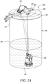
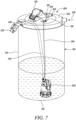
- FIGS. 1 and 2 illustrate a liquid reservoir 100.
- the liquid reservoir 100 includes a top surface 110, a side surface 120 and a bottom surface 130.
- the liquid reservoir 100 is adapted to house a liquid pump 300 (say a submersible pump 300, shown in FIG. 2 ) on the bottom surface 130.
- the liquid reservoir 100 of the present disclosure is illustrated as having a cylindrical shape and is used to store water. However, the actual implementation of the present disclosure may have a liquid reservoir 100 of any shape and size and may be used to store any type or kind of a liquid. Further, the liquid reservoir 100 may have any suitable dimensions and may preferably be made from any corrosion resistant material as per application requirements.
- the side surface 120 of the liquid reservoir 100 may be covered with a sheath of heat insulating material to maintain liquid temperature inside the liquid reservoir 100.
- the liquid reservoir 100 includes a cover 200 coupled to the top surface 110 of the liquid reservoir 100.
- the cover 200 in the illustrated embodiment is preferably circular in shape such that the circumference of the cover 200 is equal to the circumference of the top surface 110 of the liquid reservoir 100.
- the equality in the circumference of the cover 200 and the top surface 110 improves the aesthetics of the overall assembly and provides sufficient covering to the liquid reservoir 100.
- the cover 200 may have any other shape without limiting the scope of the present disclosure.
- the cover 200 may preferably be made of a transparent material, however any other type of material such as opaque, translucent and the like have also been contemplated and are well within the scope of the present disclosure. Usage of the transparent material may readily allow visual access to the components or accessories placed inside the liquid reservoir 100 such as the liquid pump 300 among others. A user may also be able to view and access whether there is sufficient liquid inside the liquid reservoir 100 to prevent dry run of the liquid pump 300.
- the cover 200 includes a first part 202 and a second part 204.
- the first part 202 and the second part 204 may have similar or different shape and size as per the requirements of the application.
- the first part 202 is adapted to mount the second part 204.
- the first part 202 removably mounts the second part 204.
- the second part 204 at least partially overlays on the first part 202.
- the second part 204 is removably held and supported by the first part 202.
- the second part 204 may be concentric with the first part 202.
- the first part 202 and the second part 204 have circular cross-sections and the first part 202 has a slightly larger cross-section than the second part 204.
- the first part 202 defines a cavity (not shown).
- the cavity may be a circular cavity.
- the cavity may have any other shape as per requirement.
- the cavity may be proximate to the center of the first part 202.
- the cavity may be offset from the center of the first part 202 but within the circumference of the first part 202.
- the cavity may be at least large enough to allow insertion of the liquid pump 300 inside the liquid reservoir 100.
- the cavity may not allow the second part 204 to pass through the cavity or fall inside the liquid reservoir 100.
- the dimensions or cross-sectional area of the second part 204 may be larger than the cavity defined by the first part 202.
- the first part 202 may be hingedly coupled to the top surface 110. In some embodiments, the first part 202 may be coupled to the top surface 110 using a latch mechanism. In some embodiments, the first part 202 may be coupled to the top surface 110 by a snap-fit coupling mechanism. The first part 202 may be coupled to the top surface 110 through any other suitable coupling mechanism as well, and the present disclosure is not limited by any such coupling mechanism in any manner.
- the cover 200 further includes a liquid pump control unit 310 coupled to the cover 200.
- the liquid pump control unit 310 is coupled to the second part 204 of the cover 200.
- the liquid pump control unit 310 may control a working or functioning of the liquid pump 300 housed on the bottom surface 130 of the liquid reservoir 100.
- the liquid pump control unit 310 includes a battery compartment (not shown) adapted to house at least one battery therein.
- the battery compartment may house the at least one battery fixed in place safely and securely while conveying power from the at least one battery.
- the liquid pump control unit 310 may include a solar panel for recharging the at least one battery.
- the solar panel may be configured to respond to solar energy, and to provide solar power for recharging the at least one battery.
- the second part 204 of the cover 200 further defines a slot 203 to allow an electric wire 500 to be coupled with the liquid pump control unit 310.
- the slot 203 allows easily placing the second part 204 of the cover 200 at intended position.
- the slot 203 allows the second part 204 of the cover 200 to encapsulate the electric wire 500 in a snugly fit manner and allows a user to ergonomically place the second part 204 of the cover 200 over the first part 202.
- the liquid pump control unit 310 may include a battery monitoring system.
- the battery monitoring system may collect voltage, current, and temperature parameters of the cell and battery pack. Further, the battery monitoring system may perform the state-of-charge estimation, charge-discharge process management, balancing management, heat management, data communication, and safety management for uninterrupted and smooth functioning of the batteries in the battery compartment and hence the smooth function of the liquid pump 300.
- the liquid pump control unit 310 may include an LCD or LED display. Important parameters concerning the functioning of the liquid pump 300 may be displayed using the LCD or LED display and may be readable by a user even in dark.
- the liquid pump control unit 310 may include a user interface.
- the user interface may allow the user to control the liquid pump control unit 310 and hence the functioning of the liquid pump 300. For example, the user may be able to switch the liquid pump 300 to on/off state or the user may alter rpm of a pump motor.
- the user interface may be a touch screen user interface, or a toggle switch type arrangement or any other suitable type of user interface which may be applicable for usage with various embodiments of the present disclosure.
- the liquid pump control unit 310 may be wirelessly connected to a smartphone 400 (as shown in FIG. 3 ).
- the liquid pump control unit 310 and hence the liquid pump 300 may be accessed or controlled via the smartphone 400 from a remote location without requiring physical presence of a user near the liquid pump control unit 310.
- the wireless connection may preferably be established via a Bluetooth or a Wi-Fi connection.
- wireless connection via any other means is also well within the scope of this disclosure.
- the smartphone 400 may also be replaced by any other suitable mobile device as well which may be compatible with various aspects of the present disclosure such as a tablet, an I-pad, a laptop or the like and the present disclosure is not limited by only the smartphone 400 in any manner.
- the liquid pump control unit 310 may include an alarm system.
- the alarm system may alert the user against dry run of the liquid pump 300.
- the alarm system may alert the user by sending a text message on a smartphone 400 of the user, or by generating an audible alarm sound or by any other such feedback means known in the art.
- the second part 204 further defines a recess 210 adapted to at least partly house the liquid pump control unit 310.
- the recess 210 is defined within the boundaries or circumference of the second part 204.
- the recess 210 is defined within the circumferential boundary of the cover 200.
- the recess 210 is defined such that is it is smaller in cross-section area than the cavity of the first part 202.
- the recess 210 is defined such that at least a part of the liquid pump control unit 310 is accessible to the user without having to remove the cover 200 from the top surface 110 of the liquid reservoir 100 or without having to remove the second part 204 from the first part 202.
- the battery compartment may also be accessible without lifting or removing the cover 200 from the liquid reservoir 100.
- the batteries may be accessed without tinkering with the contents such as, the liquid pump 300 placed inside the liquid reservoir.
- the batteries may be easily replaced or may be removed for use with other compatible tools when the liquid pump 300 is not working or functioning.
- the recess 210 includes a first portion 212 and a second portion 214 for supporting the liquid pump control unit 310.
- the shape and size of the first portion 212 and the second portion 214 may be such that the liquid pump control unit 310 may be at least partly housed in the recess 210.
- at least one of the first portion 212 or the second portion 214 of the second part 204 defines at least one opening 216 (as shown in FIG. 5 ) such that the at least one opening 216 allows electrically accessing the liquid pump 300 therethrough.
- the first portion 212 includes a protrusion 218 for supporting a part of the liquid pump control unit 310.
- the protrusion 218 of the present disclosure is a U-shaped protrusion. However, the protrusion 218 of any other shape may also be provided without limiting the scope of the present disclosure.
- the second portion 214 is illustrated to include a bowl shape depression to support remaining part of the liquid pump control unit 310.
- the second portion 214 further includes the at least one opening 216 for allowing electrical connection with the liquid pump 300.
- the electrical wire 500 (or electrical lead 500) may serve to establish electrical connection between the liquid pump control unit 310 and the liquid pump 300 (as shown in FIG. 6A ).
- the electrical wire 500 is fixedly coupled to the liquid pump control unit 310 and the liquid pump 300 at all the times.
- the liquid pump control unit 310 may be provided with a transmitter "T” and the liquid pump 300 may be provided with a receiver "R".
- the transmitter "T” may transmit power across space to the receiver "R", which may extract power and supply the power to an electrical load as per application requirements.
- the recess 210 may be integrally formed with the second part 204. In some embodiments, the recess 210 may be retrofitted to a hollow space in the second part 204. In some embodiments, the recess 210 may be rotatably coupled to the second part 204. The recess 210 may be rotatable by 360 degrees with respect to the second part 204. This rotatable feature of the recess 210 may allow the user to access the control unit 310 as per the convenience, thereby improving overall ergonomics of usage of the liquid reservoir 100.
- the recess 210 may include a LIDAR (Light Detection and Ranging) sensor electrically coupled with the liquid pump control unit 310.
- the LIDAR sensor may help identify a liquid level inside the liquid reservoir 100 to avoid or prevent a dry run of the liquid pump 300.
- the LIDAR sensor may communicate with the liquid pump control unit 310, which may further generate a warning message to be sent to the smartphone 400 or an audible alarm using the alarm system for alerting the user to take necessary actions accordingly.
- the recess 210 may include a locking mechanism (not shown) for locking a position of the liquid pump control unit 310 inside the recess 210.
- the locking mechanism may provide stability to the liquid pump control unit 310 inside the recess 210. This may prevent the electrical disconnection between the liquid pump control unit 310 and the liquid pump 300 due to environmental or inadvertent human forces. Similar to the ejection system, the locking system may also be activated by pressing the button or the switch. It should be contemplated that any other suitable mechanism may also be used for the locking system without limiting the scope of the present disclosure.
- the recess 210 may include a lid (not shown).
- the lid may be adapted to move between the open state and the closed state.
- the lid may not allow access to the liquid pump control unit 310 in the closed state of the lid.
- the lid may be protected against unauthorized access or the movement from the closed state to the open state.
- the lid may be password protected or may be opened only after recognition of fingerprint or voice of the user.
- the liquid pump control unit 310 may thus be protected against theft. Further, inadvertent opening of the lid may also be prevented.
- the lid may be made of a transparent material. Usage of the transparent material may provide safety and security of operation by ease of monitoring of the liquid pump control unit 310 or any other components present therein without a need to move the lid to the open state. Such a feature may find more prominence in case of a wet environment where unreasonable opening of the lid may lead to intrusion of water or any other potentially harmful liquid inside the liquid pump control unit 310 that may even lead to any damage.
- the lid may include a user manual to operate the liquid pump 300. The user manual may be printed or pasted on an inside surface of the lid. Thus, the liquid pump 300 may be operated by the user even with limited technical knowledge, or skill just by following the instructions on the user manual.
- the first part 202 of the cover 200 further defines another opening 220 (or an outlet opening) to allow outlet of pumped liquid from the liquid reservoir 100.
- the pumped liquid may thus be accessed via the at least one opening 220 for multiple applications.
- the opening 220 may include a regulating valve 222.
- the regulating valve 222 may be coupled to a hose 224, or the like for multiple applications.
- the first part 202 of the cover 200 may define one more opening 230 (or an inlet opening) to allow inlet of liquid inside the liquid reservoir 100 from an external liquid source via a hose (not shown).
- the liquid reservoir 100 is provided with the first part 202 of the cover 200.
- the first part 202 is coupled to the top surface 110 of the liquid reservoir 100 by any means already discussed in the present disclosure.
- the user inserts the liquid pump 300 inside the liquid reservoir 100 from above the first part 202 and the liquid reservoir 100.
- the liquid pump 300 is passed through the cavity in the first part 202 and kept on the bottom surface 130 of the liquid reservoir 100.
- the cavity is large enough to allow passage of the liquid pump 300 and may be the hand of the user.
- the hose 224 is connected to the liquid pump 300 at one end and connected to the regulating valve 222 at the other end.
- the second part 204 may be slidably engaged on the electrical wire 500 between the liquid pump control unit 310 and the liquid pump 300. After the liquid pump 300 is installed at the bottom surface 130 of the liquid reservoir 100, the second part 204 that at least partly houses the liquid pump control unit 310 in the recess 210 is removably installed or rested on the first part 202 and the operation may be commenced.
- the second part 204 with the liquid pump control unit 310, the liquid pump 300 connected to the liquid pump control unit 310 with the electrical wire 500 are taken out or removed together as one unit.
- the present disclosure provides an improved design of the cover 200 for the liquid reservoir 100, which houses the liquid pump 300.
- the cover 200 is the formed in two parts, i.e., first part 202 and the second part 204.
- the cover 200, more specifically the second part 204 of the cover includes the recess 210 to at least partly house the liquid pump control unit 310.
- the recess 210 allows for easy access to the liquid pump control unit 310 and hence the battery compartment inside the liquid pump control unit 310.
- the recess 210 allows for access to the liquid pump control unit 310 without having to open the remove the first part 202 or the second part 204 of the cover 200 of the liquid reservoir 100. Further, the recess 210 provides stability to the liquid pump control unit 310 on the cover 200 against environmental or inadvertent human forces.
Landscapes
- Engineering & Computer Science (AREA)
- Mechanical Engineering (AREA)
- General Engineering & Computer Science (AREA)
- Details Of Reciprocating Pumps (AREA)
Applications Claiming Priority (1)
| Application Number | Priority Date | Filing Date | Title |
|---|---|---|---|
| EP21215224 | 2021-12-16 |
Publications (1)
| Publication Number | Publication Date |
|---|---|
| EP4386211A1 true EP4386211A1 (de) | 2024-06-19 |
Family
ID=78918459
Family Applications (1)
| Application Number | Title | Priority Date | Filing Date |
|---|---|---|---|
| EP22213774.7A Pending EP4386211A1 (de) | 2021-12-16 | 2022-12-15 | Abdeckung für einen flüssigkeitsbehälter |
Country Status (1)
| Country | Link |
|---|---|
| EP (1) | EP4386211A1 (de) |
Citations (7)
| Publication number | Priority date | Publication date | Assignee | Title |
|---|---|---|---|---|
| US6056166A (en) * | 1997-10-15 | 2000-05-02 | Schmitz; Jon E. | Portable liquid dispenser |
| US20060251531A1 (en) * | 2005-05-06 | 2006-11-09 | Saer Elettropompe S.P.A. | In-line pumping unit |
| US20100006786A1 (en) * | 2008-07-09 | 2010-01-14 | Institut National D'optique | Method and apparatus for optical level sensing of agitated fluid surfaces |
| US20120083929A1 (en) * | 2010-09-30 | 2012-04-05 | Conrad Jr Michael L | Solar-Powered Self-Watering Planter Insert |
| US9133015B2 (en) * | 2009-06-03 | 2015-09-15 | Magic Tap, LLC | Liquid pump |
| US20180368342A1 (en) * | 2016-10-26 | 2018-12-27 | Andrew Purcell | Self watering planter assembly |
| DE102019218525A1 (de) * | 2019-11-29 | 2021-06-02 | Robert Bosch Gmbh | Energieversorgungsvorrichtung für eine Gartenpumpe und Gartenpumpe damit |
-
2022
- 2022-12-15 EP EP22213774.7A patent/EP4386211A1/de active Pending
Patent Citations (7)
| Publication number | Priority date | Publication date | Assignee | Title |
|---|---|---|---|---|
| US6056166A (en) * | 1997-10-15 | 2000-05-02 | Schmitz; Jon E. | Portable liquid dispenser |
| US20060251531A1 (en) * | 2005-05-06 | 2006-11-09 | Saer Elettropompe S.P.A. | In-line pumping unit |
| US20100006786A1 (en) * | 2008-07-09 | 2010-01-14 | Institut National D'optique | Method and apparatus for optical level sensing of agitated fluid surfaces |
| US9133015B2 (en) * | 2009-06-03 | 2015-09-15 | Magic Tap, LLC | Liquid pump |
| US20120083929A1 (en) * | 2010-09-30 | 2012-04-05 | Conrad Jr Michael L | Solar-Powered Self-Watering Planter Insert |
| US20180368342A1 (en) * | 2016-10-26 | 2018-12-27 | Andrew Purcell | Self watering planter assembly |
| DE102019218525A1 (de) * | 2019-11-29 | 2021-06-02 | Robert Bosch Gmbh | Energieversorgungsvorrichtung für eine Gartenpumpe und Gartenpumpe damit |
Similar Documents
| Publication | Publication Date | Title |
|---|---|---|
| JP5899464B2 (ja) | 分電盤システム | |
| BR102018076581B1 (pt) | Sistema de purificação de ar doméstico e método de utilização de um sistema de purificação de ar | |
| EP3795837B1 (de) | Regenschutz für die batterie einer tauchpumpe | |
| EP4386211A1 (de) | Abdeckung für einen flüssigkeitsbehälter | |
| CN111902633A (zh) | 潜水泵电池的雨水防护 | |
| WO2023208100A1 (zh) | 充电柜、储能电源以及配套充电产品 | |
| CN209250271U (zh) | 便携式无人机充电台 | |
| CN215436033U (zh) | 一种电动车电池充电柜 | |
| US20220378969A1 (en) | Smart electric incense and perfume burner | |
| CN105982497A (zh) | 一种太阳能智能邮箱 | |
| CN210007430U (zh) | 换电柜 | |
| CN214849597U (zh) | 一种配电盒及配电装置 | |
| CN214128294U (zh) | 一种便携食品加工机 | |
| CN208170699U (zh) | 一种底座防护盖、底座防护结构以及空调 | |
| CN110313223B (zh) | 电器的箱体 | |
| CN210227917U (zh) | 料理机的杯组件及料理机 | |
| CN212289533U (zh) | 一种具有防盗功能的电瓶充电器 | |
| CN219204107U (zh) | 一种储能电源 | |
| CN217192228U (zh) | 一种冲床生产用高安全性脚踏开关收纳机构 | |
| CN220584760U (zh) | 一种智慧养老安防警报装置 | |
| CN218632233U (zh) | 储能装置和具有其的储能装置控制系统 | |
| CN221194636U (zh) | 一种双电池相叠的智能门锁 | |
| CN213184143U (zh) | 一种空气开关保护罩锁紧机构 | |
| CN215816565U (zh) | 智能充电插座 | |
| CN213458318U (zh) | 一种手持电子信息装置用报警连接器 |
Legal Events
| Date | Code | Title | Description |
|---|---|---|---|
| PUAI | Public reference made under article 153(3) epc to a published international application that has entered the european phase |
Free format text: ORIGINAL CODE: 0009012 |
|
| STAA | Information on the status of an ep patent application or granted ep patent |
Free format text: STATUS: THE APPLICATION HAS BEEN PUBLISHED |
|
| PUAB | Information related to the publication of an a document modified or deleted |
Free format text: ORIGINAL CODE: 0009199EPPU |
|
| STAA | Information on the status of an ep patent application or granted ep patent |
Free format text: STATUS: THE APPLICATION HAS BEEN WITHDRAWN |
|
| PUAI | Public reference made under article 153(3) epc to a published international application that has entered the european phase |
Free format text: ORIGINAL CODE: 0009012 |
|
| 17P | Request for examination filed |
Effective date: 20231024 |
|
| AK | Designated contracting states |
Kind code of ref document: A1 Designated state(s): AL AT BE BG CH CY CZ DE DK EE ES FI FR GB GR HR HU IE IS IT LI LT LU LV MC ME MK MT NL NO PL PT RO RS SE SI SK SM TR |