EP4386201B1 - Steuerung einer windturbine mit anhand einer degradationsfunktion eingestelltem aktualisierten leistungskoeffizienten - Google Patents
Steuerung einer windturbine mit anhand einer degradationsfunktion eingestelltem aktualisierten leistungskoeffizienten Download PDFInfo
- Publication number
- EP4386201B1 EP4386201B1 EP22212800.1A EP22212800A EP4386201B1 EP 4386201 B1 EP4386201 B1 EP 4386201B1 EP 22212800 A EP22212800 A EP 22212800A EP 4386201 B1 EP4386201 B1 EP 4386201B1
- Authority
- EP
- European Patent Office
- Prior art keywords
- tsr
- power coefficient
- degradation function
- operating
- power
- Prior art date
- Legal status (The legal status is an assumption and is not a legal conclusion. Google has not performed a legal analysis and makes no representation as to the accuracy of the status listed.)
- Active
Links
Images

Classifications
-
- F—MECHANICAL ENGINEERING; LIGHTING; HEATING; WEAPONS; BLASTING
- F03—MACHINES OR ENGINES FOR LIQUIDS; WIND, SPRING, OR WEIGHT MOTORS; PRODUCING MECHANICAL POWER OR A REACTIVE PROPULSIVE THRUST, NOT OTHERWISE PROVIDED FOR
- F03D—WIND MOTORS
- F03D7/00—Controlling wind motors
- F03D7/02—Controlling wind motors the wind motors having rotation axis substantially parallel to the air flow entering the rotor
- F03D7/028—Controlling wind motors the wind motors having rotation axis substantially parallel to the air flow entering the rotor controlling wind motor output power
-
- F—MECHANICAL ENGINEERING; LIGHTING; HEATING; WEAPONS; BLASTING
- F03—MACHINES OR ENGINES FOR LIQUIDS; WIND, SPRING, OR WEIGHT MOTORS; PRODUCING MECHANICAL POWER OR A REACTIVE PROPULSIVE THRUST, NOT OTHERWISE PROVIDED FOR
- F03D—WIND MOTORS
- F03D7/00—Controlling wind motors
- F03D7/02—Controlling wind motors the wind motors having rotation axis substantially parallel to the air flow entering the rotor
- F03D7/04—Automatic control; Regulation
- F03D7/042—Automatic control; Regulation by means of an electrical or electronic controller
- F03D7/043—Automatic control; Regulation by means of an electrical or electronic controller characterised by the type of control logic
- F03D7/046—Automatic control; Regulation by means of an electrical or electronic controller characterised by the type of control logic with learning or adaptive control, e.g. self-tuning, fuzzy logic or neural network
-
- F—MECHANICAL ENGINEERING; LIGHTING; HEATING; WEAPONS; BLASTING
- F03—MACHINES OR ENGINES FOR LIQUIDS; WIND, SPRING, OR WEIGHT MOTORS; PRODUCING MECHANICAL POWER OR A REACTIVE PROPULSIVE THRUST, NOT OTHERWISE PROVIDED FOR
- F03D—WIND MOTORS
- F03D7/00—Controlling wind motors
- F03D7/02—Controlling wind motors the wind motors having rotation axis substantially parallel to the air flow entering the rotor
- F03D7/0276—Controlling wind motors the wind motors having rotation axis substantially parallel to the air flow entering the rotor controlling rotor speed, e.g. variable speed
-
- H—ELECTRICITY
- H02—GENERATION; CONVERSION OR DISTRIBUTION OF ELECTRIC POWER
- H02P—CONTROL OR REGULATION OF ELECTRIC MOTORS, ELECTRIC GENERATORS OR DYNAMO-ELECTRIC CONVERTERS; CONTROLLING TRANSFORMERS, REACTORS OR CHOKE COILS
- H02P9/00—Arrangements for controlling electric generators for the purpose of obtaining a desired output
- H02P9/008—Arrangements for controlling electric generators for the purpose of obtaining a desired output wherein the generator is controlled by the requirements of the prime mover
-
- F—MECHANICAL ENGINEERING; LIGHTING; HEATING; WEAPONS; BLASTING
- F05—INDEXING SCHEMES RELATING TO ENGINES OR PUMPS IN VARIOUS SUBCLASSES OF CLASSES F01-F04
- F05B—INDEXING SCHEME RELATING TO WIND, SPRING, WEIGHT, INERTIA OR LIKE MOTORS, TO MACHINES OR ENGINES FOR LIQUIDS COVERED BY SUBCLASSES F03B, F03D AND F03G
- F05B2260/00—Function
- F05B2260/82—Forecasts
- F05B2260/821—Parameter estimation or prediction
-
- F—MECHANICAL ENGINEERING; LIGHTING; HEATING; WEAPONS; BLASTING
- F05—INDEXING SCHEMES RELATING TO ENGINES OR PUMPS IN VARIOUS SUBCLASSES OF CLASSES F01-F04
- F05B—INDEXING SCHEME RELATING TO WIND, SPRING, WEIGHT, INERTIA OR LIKE MOTORS, TO MACHINES OR ENGINES FOR LIQUIDS COVERED BY SUBCLASSES F03B, F03D AND F03G
- F05B2270/00—Control
- F05B2270/10—Purpose of the control system
- F05B2270/103—Purpose of the control system to affect the output of the engine
- F05B2270/1033—Power (if explicitly mentioned)
-
- F—MECHANICAL ENGINEERING; LIGHTING; HEATING; WEAPONS; BLASTING
- F05—INDEXING SCHEMES RELATING TO ENGINES OR PUMPS IN VARIOUS SUBCLASSES OF CLASSES F01-F04
- F05B—INDEXING SCHEME RELATING TO WIND, SPRING, WEIGHT, INERTIA OR LIKE MOTORS, TO MACHINES OR ENGINES FOR LIQUIDS COVERED BY SUBCLASSES F03B, F03D AND F03G
- F05B2270/00—Control
- F05B2270/10—Purpose of the control system
- F05B2270/20—Purpose of the control system to optimise the performance of a machine
-
- F—MECHANICAL ENGINEERING; LIGHTING; HEATING; WEAPONS; BLASTING
- F05—INDEXING SCHEMES RELATING TO ENGINES OR PUMPS IN VARIOUS SUBCLASSES OF CLASSES F01-F04
- F05B—INDEXING SCHEME RELATING TO WIND, SPRING, WEIGHT, INERTIA OR LIKE MOTORS, TO MACHINES OR ENGINES FOR LIQUIDS COVERED BY SUBCLASSES F03B, F03D AND F03G
- F05B2270/00—Control
- F05B2270/30—Control parameters, e.g. input parameters
- F05B2270/32—Wind speeds
-
- F—MECHANICAL ENGINEERING; LIGHTING; HEATING; WEAPONS; BLASTING
- F05—INDEXING SCHEMES RELATING TO ENGINES OR PUMPS IN VARIOUS SUBCLASSES OF CLASSES F01-F04
- F05B—INDEXING SCHEME RELATING TO WIND, SPRING, WEIGHT, INERTIA OR LIKE MOTORS, TO MACHINES OR ENGINES FOR LIQUIDS COVERED BY SUBCLASSES F03B, F03D AND F03G
- F05B2270/00—Control
- F05B2270/30—Control parameters, e.g. input parameters
- F05B2270/327—Rotor or generator speeds
-
- F—MECHANICAL ENGINEERING; LIGHTING; HEATING; WEAPONS; BLASTING
- F05—INDEXING SCHEMES RELATING TO ENGINES OR PUMPS IN VARIOUS SUBCLASSES OF CLASSES F01-F04
- F05B—INDEXING SCHEME RELATING TO WIND, SPRING, WEIGHT, INERTIA OR LIKE MOTORS, TO MACHINES OR ENGINES FOR LIQUIDS COVERED BY SUBCLASSES F03B, F03D AND F03G
- F05B2270/00—Control
- F05B2270/30—Control parameters, e.g. input parameters
- F05B2270/335—Output power or torque
-
- F—MECHANICAL ENGINEERING; LIGHTING; HEATING; WEAPONS; BLASTING
- F05—INDEXING SCHEMES RELATING TO ENGINES OR PUMPS IN VARIOUS SUBCLASSES OF CLASSES F01-F04
- F05B—INDEXING SCHEME RELATING TO WIND, SPRING, WEIGHT, INERTIA OR LIKE MOTORS, TO MACHINES OR ENGINES FOR LIQUIDS COVERED BY SUBCLASSES F03B, F03D AND F03G
- F05B2270/00—Control
- F05B2270/80—Devices generating input signals, e.g. transducers, sensors, cameras or strain gauges
- F05B2270/804—Optical devices
- F05B2270/8042—Lidar systems
-
- H—ELECTRICITY
- H02—GENERATION; CONVERSION OR DISTRIBUTION OF ELECTRIC POWER
- H02P—CONTROL OR REGULATION OF ELECTRIC MOTORS, ELECTRIC GENERATORS OR DYNAMO-ELECTRIC CONVERTERS; CONTROLLING TRANSFORMERS, REACTORS OR CHOKE COILS
- H02P2101/00—Special adaptation of control arrangements for generators
- H02P2101/15—Special adaptation of control arrangements for generators for wind-driven turbines
-
- Y—GENERAL TAGGING OF NEW TECHNOLOGICAL DEVELOPMENTS; GENERAL TAGGING OF CROSS-SECTIONAL TECHNOLOGIES SPANNING OVER SEVERAL SECTIONS OF THE IPC; TECHNICAL SUBJECTS COVERED BY FORMER USPC CROSS-REFERENCE ART COLLECTIONS [XRACs] AND DIGESTS
- Y02—TECHNOLOGIES OR APPLICATIONS FOR MITIGATION OR ADAPTATION AGAINST CLIMATE CHANGE
- Y02E—REDUCTION OF GREENHOUSE GAS [GHG] EMISSIONS, RELATED TO ENERGY GENERATION, TRANSMISSION OR DISTRIBUTION
- Y02E10/00—Energy generation through renewable energy sources
- Y02E10/70—Wind energy
- Y02E10/72—Wind turbines with rotation axis in wind direction
Definitions
- the present invention relates to controlling a wind turbine with an updated power coefficient, where the updated power coefficient has been adjusted by a degradation function which is determined in an iterative adjustment process.
- Modern wind turbines are controlled and regulated continuously to ensure optimal power extraction from the wind under the current wind while at the same time ensuring that the loads on the different components of the wind turbine are at any time kept within acceptable limits and while respecting any externally set operational constraints. Based on this and following some control strategy, the turbine's control parameters are determined to perform optimally under the given conditions.
- Optimal performance requires that the turbine components perform as intended in accordance with the design.
- Wind turbines are subject to atmospheric conditions throughout their lifetime.
- a hostile environment irreversibly damages the aerodynamic properties of the blades, this being the case with, e.g. leading edge erosion.
- energy production (AEP) loss is expected if neither the blade shape nor the roughness is the designed one, and the turbine controller is not aware of the change.
- a common control scheme of a wind turbine in a partial load operation mode is based on a tip-speed ratio (TSR) tracking scheme, which, based on the estimation of the rotor-effective wind speed, determines a power setpoint.
- TSR tip-speed ratio
- Such a control scheme, as well as many other wind turbine control features, relies on a nominal or predetermined power coefficient (C p ). If the predetermined C p coefficient does not accurately resemble the actual power coefficient, the turbine will operate at a different operating point than the intended setpoint, leading to sub-optimal operations.
- Document EP 3 088 733 A1 provides an example of adapting a Cp coefficient.
- wind speed estimator is based on a power or torque balance between the aerodynamic power or torque of the rotor and the electrical power or torque of the generator.
- Such wind speed estimator may include an internal model of which the estimation accuracy is sensitive to the accuracy of the power coefficient information with respect to the actual power coefficient.
- the inventors of the present invention have realized that an excitation free learning algorithm for the calibration of the internal physical model parameters can be provided while operating the wind turbine using standard closed loop measurements, complemented with an external measurement of the rotor effective wind speed (REWS).
- the learning algorithm is thereby largely nondisruptive.
- the learning algorithm calibrates the internal model to accurately represent the actual aerodynamic turbine properties by providing an updated power coefficient which matches the operating turbine better than the predetermined (or design) power coefficient.
- the learning algorithm is based on the iterative adjustment process.
- An iterative adjustment process is performed for at least one selected TSR, however in order to determine the degradation function in a broader range of the partial load region, advantageously the iterative adjustment process is performed for a number of selected TSRs.
- An outer iterative loop may be performed with selected TSRs at further values, including higher selected TSR values and lower selected lower TSR values with respect to the nominal TSR reference or setpoint value.
- the iterative adjustment process is performed using at least three different selected TSRs, each TSR being within the partial load region of constant pitch angle and variable rotor speed. However more selected TSRs may be used.
- the different selected TSRs may be set at predetermined values or selected by a predetermined selection algorithms which based on the measured TSR for the first (or earlier) iteration(s) is capable of determining further selected TSRs within the partial load region of constant pitch angle and variable rotor speed.
- the degradation function is calculated based on the measurement set.
- the degradation function may be understood as an estimated degradation function, as the aim is to estimate a degradation function that represents the values of the measurement set.
- the calculation of the degradation function that represents the values of the measurement set comprising taking the pseudoinverse.
- the pseudoinverse may be taken of a vector expressing the calculated generator power obtained using the wind speed measurements and rotor speed measurements of the measurement set and the predetermined power coefficient.
- the iterative adjustment process results in a number of calculated degradation function values at corresponding mean operating TSRs of the measurement sets.
- the mean operating TSR values span a range of values, even though for the first iteration, this range is just one point. Based on the values a continuous degradation function is obtained, e.g. by interpolating the calculated degradation function for the range of the mean operating TSR values.
- the method of the present invention requires a measured rotor effective wind speed.
- any suitable sensor or device may be used for measuring the rotor effective wind speed.
- the measured rotor effective wind speed is obtained using a lidar and/or using a wind speed anemometer arranged on the wind turbine.
- the wind speed anemometer measurements may be filtered with a time-constant, preferably in the range between 30 seconds (s) and 120 seconds (s). By filtering the wind speed anemometer measurements with a time constant, it may be possible to adjust for the inertial delay of a wind speed change on the rotating rotor. The actual time constant may depend on the turbine design.
- a measurement set should be obtained for a suitable long period so that the measurement set average out any dynamic effects.
- the measurement set is obtained over a measurement period being selected so that sufficient data is obtained to reduce the variance of the estimate, but should not be too long as the data set grows with the measurement period.
- a period is selected as a compromise between a minimal amount of data to ensure a low variance and computing resources.
- the measurement period is predefined based on expected wind turbine conditions, and the measurement period may be selected to be at least 1000 s, such as between 1000 s and 10000 s.
- the adjustment process may be conditioned upon the turbulence intensity being below a predefined turbulence intensity level.
- the wind turbine may be operated using the updated power coefficient.
- TSR tip-speed ratio
- Application of the method of the present invention may also be used for turbine monitoring purposes. For example, by determining that a scaling of the operating power coefficient is needed without any realizable reason is an indication of fault of the turbine. For example, if the power coefficient has recently been changed by the method of the present invention and a new correction is needed, is likely an indication that a fault has occurred and a service inspection would be warranted.
- a non-transient, computer-readable storage medium storing instructions thereon that when executed by one or more processors cause the one or more processors to execute a method according to the first aspect.
- the method may be implemented as a computer program product, and the computer program product may be provided on the computer-readable storage medium or being downloadable from a communication network.
- the computer program product comprises instructions to cause a data processing system, e.g. in the form of a controller, to carry out the instruction when loaded onto the data processing system.
- a controller for controlling a wind turbine in a partial load operation mode in accordance with the first aspect.
- a wind turbine comprising the controller.
- a controller may be a unit or collection of functional units which comprises one or more processors, input/output interface(s), and a memory capable of storing instructions that can be executed by a processor.
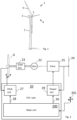
- FIG. 1 illustrates, in a schematic perspective view, an example of a wind turbine 1.
- the wind turbine 1 includes a tower 2, a nacelle 3 disposed at the apex of the tower, and a rotor 4 operatively coupled to a generator housed inside the nacelle 3.
- the nacelle houses miscellaneous components required for converting wind energy into electrical energy and various components needed to operate, control, and optimize the performance of the wind turbine 1.
- the rotor 4 of the wind turbine includes a central hub 5 and a plurality of blades 6 that project outwardly from the central hub 5. In the illustrated embodiment, the rotor 4 includes three blades 6, but the number may vary.
- the wind turbine comprises a control system.
- the control system may be placed inside the nacelle or distributed at a number of locations inside (or externally to) the turbine and communicatively connected.
- FIG. 2 schematically illustrates an embodiment of a control system 20 together with elements of a wind turbine.
- the wind turbine comprises rotor blades 6, which are mechanically connected to an electrical generator 22 via gearbox 23. In direct drive systems, and other systems, the gearbox may not be present.
- the electrical power generated by the generator 22 is injected into a power grid 24 via an electrical converter 25.
- the electrical generator 22 and the converter 25 may be based on a full-scale converter (FSC) architecture or a doubly fed induction generator (DFIG) architecture, but other types may be used.
- FSC full-scale converter
- DFIG doubly fed induction generator
- the control system 20 comprises several elements, including at least one main controller 200 with a processor and memory so that the processor is capable of executing computing tasks based on instructions stored in the memory.
- the wind turbine controller ensures that in operation the wind turbine generates a requested power output level. This is obtained by adjusting the pitch angle and/or the power extraction of the converter.
- the control system comprises a pitch system including a pitch controller 27 using a pitch reference 28 and a power system including a power controller 29 using a power reference 26.
- the power controller controls the various electric components of the generator converter system to deliver the requested power, hereunder controls the torque of the generator that is needed to extract the requested power by the rotor from the wind.
- Figure 2 further illustrates a wind sensor 201 for measuring the rotor effective wind speed.
- the wind sensor may e.g. be a lidar mounted on the wind turbine, or at another appropriate location.
- the wind sensor may be a wind anemometer arranged for measuring the rotor effective wind speed.
- Anemometer wind sensors are typically mounted on the nacelle.
- the wind sensor is illustrated as a cup anemometer, this however is only for illustrative reasons.
- the actual type of wind sensor may be as mentioned above, and any type suitable for measuring the rotor effective wind speed.
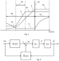
- Figure 3 illustrates a general control scheme divided into a partial load operation area 30 and a full load operation area 31.
- the wind turbine controller may adjust the pitch ( ⁇ ) of the blades to an optimal pitch angle, typically around zero degrees. This ensures that while the wind turbine is not producing the maximum amount of electricity it is able to produce it is controlled to capture as much energy from the wind as it can. If there is sufficient energy in the wind (i.e. the wind speed is above the rated wind speed 33) the wind turbine will operate in full load operation 31 while generating rated power 32, and control of the wind turbine blade pitch is used to turn the blades out of the wind to avoid overspeed of the generator and/or unsafe operation of the turbine while keeping the rotor speed constant.
- the figure moreover shows rotor speed ( ⁇ ) and generated power (P).
- the turbine While operating in the partial load region 30, the turbine may be controlled based on a tip-speed ratio (TSR) tracking scheme, which based on an estimated wind speed, determines a power setpoint P.
- the estimated wind speed being determined based on a power or torque balance between the aerodynamic power or torque of the rotor and the electrical power or torque of the generator.
- the TSR tracking scheme ensures operation in accordance with an operating power coefficient. It is important that the operating power coefficient closely matches the real or actual power coefficient of the wind turbine. To ensure this, the operating power coefficient may be adjusted in an iterative adjustment process in accordance with embodiments of the present invention.
- Figure 4 illustrates in a schematic manner elements of a wind speed estimator based on a power or torque balance between the aerodynamic power or torque of the rotor and the electrical power or torque of the generator.
- the actual rotor speed ( ⁇ r ) is measured by a rotor speed sensor and input into a computing block which determines the operating rotor power P r ( t ) as a sum of the power setpoint, P g , and the power obtained from the rotor inertia.
- PI proportional-integral
- Figure 5 illustrates a flow diagram of elements of the iterative adjustment process, also referred to as the learning process, for determining the degradation function and thereby the updated power coefficient.
- the iterative adjustment process comprises, in a step 50, to set an updated power coefficient, Cp, as a predetermined power coefficient multiplied by a degradation function, ⁇ ( ⁇ ).
- the updated power coefficient is set as a function of the tip-speed ratio, TSR, ⁇ :
- the predetermined power coefficient may be the design power coefficient for the wind turbine, or it may be a power coefficient obtained in an earlier adjustment process.
- the wind turbine is operated at a selected tip-speed ratio ⁇ .
- the selected TSR may in a first iteration process be selected as the TSR corresponding to the current measured or estimated wind speed, i.e. the controller setpoint.
- the selected TSR is constrained downwards by a minimum speed of the generator, such as a minimum static generator speed 35.
- the TSR is constrained upwards by the rated generator speed 36.
- the execution of the iterative adjustment process is therefore constrained by the wind speed as the selected TSR is selected for the operational region 34 of constant pitch angle and variable rotor speed of the partial load region.
- a measurement set comprising a series of measurements of at least the generator power, the rotor effective wind speed and the rotor speed is obtained.
- the measurement set: D P g T , U ⁇ T , ⁇ r T can be expressed as a set of three vectors of sample values obtained during closed-loop operation of the wind turbine for a measurement period.
- the degradation function that represents the values of the measurement set for the selected tip-speed ratio is calculated.
- the generator power, the power coefficient and the wind speed are closely connected, and by measuring generator power over the period of time it can be determined if the predetermined power coefficient represents the measured power coefficient, and if not so, an updated power coefficient can be determined which represents the measured power coefficient more closely.
- an updated power coefficient can be determined which represents the measured power coefficient more closely.
- mismatch is expressed by use of the degradation function, which takes the value 1 if the measured power coefficient represents the model power coefficient or is otherwise not equal to 1.
- the adjustment process is conditioned upon the turbulence intensity being below a predefined turbulence intensity level, thereby ensuring steady-state conditions, as least for in average for the duration of the measurement set. In general, however, a limit on the turbulence intensity need not be set.
- an estimated degradation function may be applied:
- a degradation function that represents the values of the measurement set is thereby calculated. That is the value of the degradation function at the mean operating TSR is thereby calculated.
- the adjustment process is performed with the wind turbine in a partial load operation mode based on a tip-speed ratio (TSR) tracking scheme based on an estimated wind speed.
- TSR tip-speed ratio
- the model uncertainty in the control scheme may result in the commanded tip-speed ratio setpoint not being equal to the actual averaged TSR operating point (the mean operating TSR).
- step 53 the mean operating TSR of the measurement set is calculated, and the degradation function is set equal to the calculated degradation function for the mean operating TSR.
- step 54 a continuous degradation function for the range of the mean operating TSR values is determined, and the operating power coefficient is set as the updated power coefficient using the continuous degradation function in the range of the mean operating TSR values.
- the degradation function, and thereby the operating power coefficient is set based on as the continuous degradation function in the range of the mean operating TSR values.
- the operating power coefficient may be set constant, e.g. using the calculated degradation function of the respective end-points of the range of the mean operating TSRs.
- the determination of the continuous degradation function may comprise interpolating the calculated degradation function for the range of the mean operating TSR values.
- Such interpolation may be a linear interpolation, a spline-based interpolation, or any other suitable interpolation.
- the degradation function may be set equal to the single degradation function value for the entire TSR operating range of the partial load region or the range may be set to only comprise the single value.
- a preset difference, ⁇ , between the selected tip-speed ratio and an average tip-speed ratio of the measurement set (mean operating TSR) is determined, for example by setting up the below criterion: ⁇ j ⁇ ⁇ ⁇ ⁇ i ⁇ j ⁇ ⁇ ⁇ ,
- the operating power coefficient is set as the updated power coefficient for the selected TSR, and another iteration is performed.
- the preset difference may be set to a smaller value, and the iterative adjustment process may be continued 57 with the smaller preset difference.
- the iteration process is terminated if the difference is below a preset difference 58.
- the degradation function may be learned in a broader interval of the partial load region.
- a different TSR is selected and the iterative adjustment process is repeated with the different selected TSR. That is the wind turbine is commanded to operate at a different TSR setpoint for the subsequent iterative adjustment process.
- the iterative adjustment process is performed using at least three different selected TSRs, each TSR being within the partial load region of constant pitch angle and variable rotor speed.
- the iterative adjustment process may be performed for more than three different selected TSR, if a more finely defined degradation function is desired.
- the selected TSR may be selected at higher TSR value than the any value of an earlier used TSR value(s).
- the selected TSR may be selected at lower TSR value than the any value of an earlier used TSR value(s).
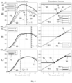
- Figure 6 illustrates a full learning cycle in different stages of the iterative adjustment process in terms of the power coefficient and the degradation function.
- Fig. 6 the iterative adjustment process is illustrated based on simulation.
- the simulations have been performed on the NREL 5-MW reference wind turbine. Simulations obtained on the NREL reference wind turbine is known and available to the skilled person.
- the NREL reference wind turbine is for example described in the Technical Report NREL/TP-500-38060 from February 2009 by J. Jonkman, S. Butterfield, W. Musial, and G. Scot entitled "Definition of a 5-MW Reference Wind Turbine for Offshore System Development ".
- a realistic turbulent wind field is used with a mean speed of 7 m/s and with IEC normal turbulence model (NTM) and class A turbulence characteristics (IEC, 2019).
- the actual power coefficient C p is marked by reference numeral 60, and the actual degradation function is marked by reference numeral 61.
- the learning algorithm relies on the availability of the data set D i throughout the consequent iterations i in the full learning cycle.
- the selected TSR is thus set to 8.5 as the controller setpoint for tip-speed ratio.
- a first updated power coefficient is ⁇ P ,1 is obtained, marked 65.
- the commanded tip-speed ratio setpoint is not equal to the actual averaged TSR operating (mean operating TSR of D 1 ).
- the mean operating TSR is illustrated by the dashed line marked 66.
- This learning routine is repeated until the convergence criterion is met in accordance with the preset difference.
- the degradation function after the iterations for the first selected TSR is thus obtained for two mean operating TSRs 64, 67 defining the end points in the range 74 of the TSR values.
- a linear degradation function 61 is shown in Fig. 6 .
- the degradation function is not known before performing the iterative adjustment process, and a continuous degradation function for the range of the mean operating TSR values is determined, e.g. by fitting the set of degradation functions values of the mean operating TSRs to a linear function which would be co-located with the shown degradation function 61 for the shown example.
- the final estimated degradation function ⁇ 4 is marked 72 and the ⁇ P ,4 is marked 73.
- ⁇ ( ⁇ ) can be learned in a broad operating domain where actual turbine operation is feasible, and accurately reflects the actual turbine power coefficient properties throughout the explored domain.
- the broad domain being defined by the range of the mean operating TSR values.
- the degradation function may be set constant, e.g. as the calculated degradation function of the respective end-points, 75, 76.
Landscapes
- Engineering & Computer Science (AREA)
- General Engineering & Computer Science (AREA)
- Mechanical Engineering (AREA)
- Sustainable Development (AREA)
- Sustainable Energy (AREA)
- Chemical & Material Sciences (AREA)
- Combustion & Propulsion (AREA)
- Life Sciences & Earth Sciences (AREA)
- Power Engineering (AREA)
- Evolutionary Computation (AREA)
- Artificial Intelligence (AREA)
- Physics & Mathematics (AREA)
- Fuzzy Systems (AREA)
- Mathematical Physics (AREA)
- Software Systems (AREA)
- Wind Motors (AREA)
Claims (15)
- Verfahren zum Steuern einer Windkraftanlage in einem Teillastbetriebsmodus basierend auf einem Spitzengeschwindigkeitsverhältnis-, (TSR)-Verfolgungsschema, das basierend auf einer geschätzten Windgeschwindigkeit einen Leistungssollwert bestimmt, wobei die geschätzte Windgeschwindigkeit basierend auf einem Leistungs- oder Drehmomentgleichgewicht zwischen der aerodynamischen Leistung oder dem Drehmoment des Rotors und der elektrischen Leistung oder dem Drehmoment des Generators bestimmt wird, wobei das TSR-Verfolgungsschema für einen Betrieb in Übereinstimmung mit einem Betriebsleistungskoeffizienten sorgt, und wobei der Betriebsleistungskoeffizient in einem iterativen Anpassungsprozess angepasst wurde,
wobei der iterative Anpassungsprozess umfasst:Einstellen eines aktualisierten Leistungskoeffizienten als einen vorbestimmten Leistungskoeffizienten multipliziert mit einer Energieverlustfunktion;beim Betreiben der Windkraftanlage bei einem ausgewählten TSR, Erhalten eines Messwertsatzes, der eine Reihe von Messungen von mindestens einer Generatorleistung, einer effektiven Rotorwindgeschwindigkeit und einer Rotorgeschwindigkeit umfasst;Berechnen der Energieverlustfunktion, welche die Werte des Messsatzes darstellt;Berechnen eines mittleren Betriebs-TSR des Messsatzes und Einstellen der Energieverlustfunktion gleich der berechneten Energieverlustfunktion für den mittleren Betriebs-TSR;Bestimmen einer kontinuierlichen Energieverlustfunktion für einen Bereich des/der mittleren TSR-Betriebswerte/s und Einstellen des Betriebsleistungskoeffizienten als aktualisierten Leistungskoeffizienten unter Verwendung der kontinuierlichen Energieverlustfunktion im Bereich der mittleren TSR-Betriebswerte;Bestimmen einer Differenz zwischen dem ausgewählten TSR und dem mittleren Betriebs-TSR;wenn die Differenz über einer voreingestellten Differenz liegt, Einstellen des Betriebsleistungskoeffizienten als aktualisierten Leistungskoeffizienten für den ausgewählten TSR und Durchführen einer weiteren Iteration. - Verfahren nach Anspruch 1, das weiter Einstellen des ausgewählten TSR auf einen höheren TSR und Durchführen des iterativen Anpassungsprozesses unter Verwendung des ausgewählten höheren TSR umfasst.
- Verfahren nach einem der vorstehenden Ansprüche, das weiter Einstellen des ausgewählten TSR auf einen niedrigeren TSR und Durchführen des iterativen Anpassungsprozesses unter Verwendung des ausgewählten niedrigeren TSR umfasst.
- Verfahren nach einem der vorstehenden Ansprüche, wobei der iterative Anpassungsprozess unter Verwendung von mindestens drei unterschiedlichen ausgewählten TSRs durchgeführt wird, wobei sich jeder TSR innerhalb des Teillastbereichs mit konstantem Blattwinkel und variabler Rotorgeschwindigkeit befindet.
- Verfahren nach einem der vorstehenden Ansprüche, wobei die Berechnung der Energieverlustfunktion, welche die Werte des Messsatzes darstellt, Annehmen der Pseudoinverse umfasst.
- Verfahren nach einem der vorstehenden Ansprüche, wobei die Bestimmung der kontinuierlichen Energieverlustfunktion Interpolieren der berechneten Energieverlustfunktion für den Bereich der mittleren Betriebs-TSR-Werte umfasst.
- Verfahren nach einem der vorstehenden Ansprüche, wobei die gemessene effektive Rotorwindgeschwindigkeit unter Verwendung eines Lidar erhalten wird.
- Verfahren nach einem der vorstehenden Ansprüche, wobei die gemessene effektive Rotorwindgeschwindigkeit unter Verwendung eines an der Windkraftanlage angeordneten Windgeschwindigkeitsanemometers erhalten wird.
- Verfahren nach Anspruch 8, wobei die Windgeschwindigkeitsanemometermessungen mit einer Zeitkonstante gefiltert werden.
- Verfahren nach einem der vorstehenden Ansprüche, wobei der Messwertsatz über einen ausgewählten Messzeitraum hinweg erhalten wird.
- Verfahren nach einem der vorstehenden Ansprüche, wobei der Anpassungsprozess durch die Turbulenzintensität bedingt ist, die unter einem vordefinierten Turbulenzintensitätsniveau liegt.
- Verfahren nach einem der vorstehenden Ansprüche, wobei die Windkraftanlage nach dem iterativen Anpassungsprozess unter Verwendung des aktualisierten Leistungskoeffizienten betrieben wird.
- Nichtflüchtiges computerlesbares Speichermedium, auf dem Anweisungen gespeichert sind, die, wenn sie von einem oder mehreren Prozessoren ausgeführt werden, den einen oder mehrere Prozessoren veranlassen, ein Verfahren nach einem vorstehenden Anspruch auszuführen.
- Steuereinheit zum Steuern einer Windkraftanlage in einem Teillastbetriebsmodus nach einem der Ansprüche 1 bis 12.
- Windkraftanlage, die eine Steuereinheit nach Anspruch 14 umfasst.
Priority Applications (2)
| Application Number | Priority Date | Filing Date | Title |
|---|---|---|---|
| EP22212800.1A EP4386201B1 (de) | 2022-12-12 | 2022-12-12 | Steuerung einer windturbine mit anhand einer degradationsfunktion eingestelltem aktualisierten leistungskoeffizienten |
| US18/537,370 US12044212B2 (en) | 2022-12-12 | 2023-12-12 | Controlling a wind turbine with an updated power coefficient adjusted by a degradation function |
Applications Claiming Priority (1)
| Application Number | Priority Date | Filing Date | Title |
|---|---|---|---|
| EP22212800.1A EP4386201B1 (de) | 2022-12-12 | 2022-12-12 | Steuerung einer windturbine mit anhand einer degradationsfunktion eingestelltem aktualisierten leistungskoeffizienten |
Publications (3)
| Publication Number | Publication Date |
|---|---|
| EP4386201A1 EP4386201A1 (de) | 2024-06-19 |
| EP4386201C0 EP4386201C0 (de) | 2025-06-04 |
| EP4386201B1 true EP4386201B1 (de) | 2025-06-04 |
Family
ID=84488559
Family Applications (1)
| Application Number | Title | Priority Date | Filing Date |
|---|---|---|---|
| EP22212800.1A Active EP4386201B1 (de) | 2022-12-12 | 2022-12-12 | Steuerung einer windturbine mit anhand einer degradationsfunktion eingestelltem aktualisierten leistungskoeffizienten |
Country Status (2)
| Country | Link |
|---|---|
| US (1) | US12044212B2 (de) |
| EP (1) | EP4386201B1 (de) |
Family Cites Families (3)
| Publication number | Priority date | Publication date | Assignee | Title |
|---|---|---|---|---|
| EP2719895B1 (de) * | 2012-10-09 | 2017-07-26 | GE Renewable Technologies | Verfahren zur Überwachung einer Windturbine |
| US10473088B2 (en) * | 2015-03-13 | 2019-11-12 | General Electric Company | System and method for variable tip-speed-ratio control of a wind turbine |
| EP3088733B1 (de) * | 2015-04-27 | 2018-10-17 | Envision Energy (Jiangsu) Co., Ltd. | Verfahren zum Betrieb einer Windturbine auf Grundlage des Verschleisses der Windturbinenschaufel |
-
2022
- 2022-12-12 EP EP22212800.1A patent/EP4386201B1/de active Active
-
2023
- 2023-12-12 US US18/537,370 patent/US12044212B2/en active Active
Also Published As
| Publication number | Publication date |
|---|---|
| EP4386201C0 (de) | 2025-06-04 |
| US20240209834A1 (en) | 2024-06-27 |
| EP4386201A1 (de) | 2024-06-19 |
| US12044212B2 (en) | 2024-07-23 |
Similar Documents
| Publication | Publication Date | Title |
|---|---|---|
| EP3749853B1 (de) | Bestimmung von steuerungseinstellungen für eine windturbine | |
| US8269361B2 (en) | Adaptive adjustment of the blade pitch angle of a wind turbine | |
| CN107667220B (zh) | 考虑疲劳量度的风力涡轮机控制 | |
| Bossanyi et al. | Validation of individual pitch control by field tests on two-and three-bladed wind turbines | |
| EP3221582B1 (de) | Verfahren zur schätzung einer windgeschwindigkeit einschliesslich der berechnung eines für schaufeltorsion angepassten spitzenwinkels | |
| EP3221581B1 (de) | Verfahren zur schätzung der windgeschwindigkeit auf stabile weise | |
| CN109312714B (zh) | 考虑噪声的风力涡轮机的控制 | |
| CN115768980B (zh) | 风力涡轮机中的温度估计 | |
| CN103758699A (zh) | 一种风力发电机组的桨距角控制方法及桨距角控制器 | |
| CN109416523A (zh) | 在低电压电网事件期间使用mpc控制风力涡轮机 | |
| CN108150351B (zh) | 风力发电机组的启动、并网控制方法和装置、存储介质 | |
| EP4115079B1 (de) | Verfahren und vorrichtung zur steuerung eines windparks | |
| EP4386201B1 (de) | Steuerung einer windturbine mit anhand einer degradationsfunktion eingestelltem aktualisierten leistungskoeffizienten | |
| EP3712430A1 (de) | Erkennung einer leistungsänderung einer windturbine | |
| EP4365437B1 (de) | Steuerung einer windturbine mit skaliertem leistungskoeffizienten | |
| EP3828408A1 (de) | Verfahren und vorrichtung zur computerimplementierten überwachung einer windturbine | |
| EP3511563A1 (de) | Obergrenze für ein windparksteuergerät | |
| EP3942176B1 (de) | Verfahren zur bestimmung von leistungsparametern in echtzeit | |
| EP4464891A1 (de) | Überwachung des betriebs einer windturbine | |
| CN113423949B (zh) | 用于运行风能设备的方法、风能设备和计算机程序产品 | |
| CN120457276A (zh) | 确定风力涡轮机处的风速 | |
| DK201970630A1 (en) | A wind speed estimator for a wind turbine | |
| CN114060210A (zh) | 风电机组的降载控制方法、装置以及控制系统 |
Legal Events
| Date | Code | Title | Description |
|---|---|---|---|
| PUAI | Public reference made under article 153(3) epc to a published international application that has entered the european phase |
Free format text: ORIGINAL CODE: 0009012 |
|
| STAA | Information on the status of an ep patent application or granted ep patent |
Free format text: STATUS: THE APPLICATION HAS BEEN PUBLISHED |
|
| AK | Designated contracting states |
Kind code of ref document: A1 Designated state(s): AL AT BE BG CH CY CZ DE DK EE ES FI FR GB GR HR HU IE IS IT LI LT LU LV MC ME MK MT NL NO PL PT RO RS SE SI SK SM TR |
|
| STAA | Information on the status of an ep patent application or granted ep patent |
Free format text: STATUS: REQUEST FOR EXAMINATION WAS MADE |
|
| 17P | Request for examination filed |
Effective date: 20241121 |
|
| RBV | Designated contracting states (corrected) |
Designated state(s): AL AT BE BG CH CY CZ DE DK EE ES FI FR GB GR HR HU IE IS IT LI LT LU LV MC ME MK MT NL NO PL PT RO RS SE SI SK SM TR |
|
| GRAP | Despatch of communication of intention to grant a patent |
Free format text: ORIGINAL CODE: EPIDOSNIGR1 |
|
| STAA | Information on the status of an ep patent application or granted ep patent |
Free format text: STATUS: GRANT OF PATENT IS INTENDED |
|
| RIC1 | Information provided on ipc code assigned before grant |
Ipc: F03D 7/02 20060101ALI20250310BHEP Ipc: F03D 7/04 20060101AFI20250310BHEP |
|
| INTG | Intention to grant announced |
Effective date: 20250321 |
|
| GRAS | Grant fee paid |
Free format text: ORIGINAL CODE: EPIDOSNIGR3 |
|
| GRAA | (expected) grant |
Free format text: ORIGINAL CODE: 0009210 |
|
| STAA | Information on the status of an ep patent application or granted ep patent |
Free format text: STATUS: THE PATENT HAS BEEN GRANTED |
|
| AK | Designated contracting states |
Kind code of ref document: B1 Designated state(s): AL AT BE BG CH CY CZ DE DK EE ES FI FR GB GR HR HU IE IS IT LI LT LU LV MC ME MK MT NL NO PL PT RO RS SE SI SK SM TR |
|
| REG | Reference to a national code |
Ref country code: GB Ref legal event code: FG4D |
|
| REG | Reference to a national code |
Ref country code: CH Ref legal event code: EP |
|
| REG | Reference to a national code |
Ref country code: DE Ref legal event code: R096 Ref document number: 602022015444 Country of ref document: DE |
|
| REG | Reference to a national code |
Ref country code: IE Ref legal event code: FG4D |
|
| U01 | Request for unitary effect filed |
Effective date: 20250613 |
|
| U07 | Unitary effect registered |
Designated state(s): AT BE BG DE DK EE FI FR IT LT LU LV MT NL PT RO SE SI Effective date: 20250627 |
|
| PG25 | Lapsed in a contracting state [announced via postgrant information from national office to epo] |
Ref country code: ES Free format text: LAPSE BECAUSE OF FAILURE TO SUBMIT A TRANSLATION OF THE DESCRIPTION OR TO PAY THE FEE WITHIN THE PRESCRIBED TIME-LIMIT Effective date: 20250604 |
|
| PG25 | Lapsed in a contracting state [announced via postgrant information from national office to epo] |
Ref country code: GR Free format text: LAPSE BECAUSE OF FAILURE TO SUBMIT A TRANSLATION OF THE DESCRIPTION OR TO PAY THE FEE WITHIN THE PRESCRIBED TIME-LIMIT Effective date: 20250905 Ref country code: NO Free format text: LAPSE BECAUSE OF FAILURE TO SUBMIT A TRANSLATION OF THE DESCRIPTION OR TO PAY THE FEE WITHIN THE PRESCRIBED TIME-LIMIT Effective date: 20250904 |
|
| PG25 | Lapsed in a contracting state [announced via postgrant information from national office to epo] |
Ref country code: PL Free format text: LAPSE BECAUSE OF FAILURE TO SUBMIT A TRANSLATION OF THE DESCRIPTION OR TO PAY THE FEE WITHIN THE PRESCRIBED TIME-LIMIT Effective date: 20250604 |
|
| PG25 | Lapsed in a contracting state [announced via postgrant information from national office to epo] |
Ref country code: HR Free format text: LAPSE BECAUSE OF FAILURE TO SUBMIT A TRANSLATION OF THE DESCRIPTION OR TO PAY THE FEE WITHIN THE PRESCRIBED TIME-LIMIT Effective date: 20250604 |
|
| PG25 | Lapsed in a contracting state [announced via postgrant information from national office to epo] |
Ref country code: RS Free format text: LAPSE BECAUSE OF FAILURE TO SUBMIT A TRANSLATION OF THE DESCRIPTION OR TO PAY THE FEE WITHIN THE PRESCRIBED TIME-LIMIT Effective date: 20250904 |