EP4365437B1 - Steuerung einer windturbine mit skaliertem leistungskoeffizienten - Google Patents
Steuerung einer windturbine mit skaliertem leistungskoeffizienten Download PDFInfo
- Publication number
- EP4365437B1 EP4365437B1 EP22205531.1A EP22205531A EP4365437B1 EP 4365437 B1 EP4365437 B1 EP 4365437B1 EP 22205531 A EP22205531 A EP 22205531A EP 4365437 B1 EP4365437 B1 EP 4365437B1
- Authority
- EP
- European Patent Office
- Prior art keywords
- power
- power coefficient
- rotor
- coefficient
- wind turbine
- Prior art date
- Legal status (The legal status is an assumption and is not a legal conclusion. Google has not performed a legal analysis and makes no representation as to the accuracy of the status listed.)
- Active
Links
Images
Classifications
-
- F—MECHANICAL ENGINEERING; LIGHTING; HEATING; WEAPONS; BLASTING
- F03—MACHINES OR ENGINES FOR LIQUIDS; WIND, SPRING, OR WEIGHT MOTORS; PRODUCING MECHANICAL POWER OR A REACTIVE PROPULSIVE THRUST, NOT OTHERWISE PROVIDED FOR
- F03D—WIND MOTORS
- F03D7/00—Controlling wind motors
- F03D7/02—Controlling wind motors the wind motors having rotation axis substantially parallel to the air flow entering the rotor
- F03D7/022—Adjusting aerodynamic properties of the blades
- F03D7/0224—Adjusting blade pitch
-
- F—MECHANICAL ENGINEERING; LIGHTING; HEATING; WEAPONS; BLASTING
- F03—MACHINES OR ENGINES FOR LIQUIDS; WIND, SPRING, OR WEIGHT MOTORS; PRODUCING MECHANICAL POWER OR A REACTIVE PROPULSIVE THRUST, NOT OTHERWISE PROVIDED FOR
- F03D—WIND MOTORS
- F03D7/00—Controlling wind motors
- F03D7/02—Controlling wind motors the wind motors having rotation axis substantially parallel to the air flow entering the rotor
- F03D7/028—Controlling wind motors the wind motors having rotation axis substantially parallel to the air flow entering the rotor controlling wind motor output power
-
- F—MECHANICAL ENGINEERING; LIGHTING; HEATING; WEAPONS; BLASTING
- F03—MACHINES OR ENGINES FOR LIQUIDS; WIND, SPRING, OR WEIGHT MOTORS; PRODUCING MECHANICAL POWER OR A REACTIVE PROPULSIVE THRUST, NOT OTHERWISE PROVIDED FOR
- F03D—WIND MOTORS
- F03D1/00—Wind motors with rotation axis substantially parallel to the air flow entering the rotor
-
- F—MECHANICAL ENGINEERING; LIGHTING; HEATING; WEAPONS; BLASTING
- F03—MACHINES OR ENGINES FOR LIQUIDS; WIND, SPRING, OR WEIGHT MOTORS; PRODUCING MECHANICAL POWER OR A REACTIVE PROPULSIVE THRUST, NOT OTHERWISE PROVIDED FOR
- F03D—WIND MOTORS
- F03D7/00—Controlling wind motors
- F03D7/02—Controlling wind motors the wind motors having rotation axis substantially parallel to the air flow entering the rotor
- F03D7/04—Automatic control; Regulation
- F03D7/042—Automatic control; Regulation by means of an electrical or electronic controller
- F03D7/043—Automatic control; Regulation by means of an electrical or electronic controller characterised by the type of control logic
- F03D7/046—Automatic control; Regulation by means of an electrical or electronic controller characterised by the type of control logic with learning or adaptive control, e.g. self-tuning, fuzzy logic or neural network
-
- F—MECHANICAL ENGINEERING; LIGHTING; HEATING; WEAPONS; BLASTING
- F05—INDEXING SCHEMES RELATING TO ENGINES OR PUMPS IN VARIOUS SUBCLASSES OF CLASSES F01-F04
- F05B—INDEXING SCHEME RELATING TO WIND, SPRING, WEIGHT, INERTIA OR LIKE MOTORS, TO MACHINES OR ENGINES FOR LIQUIDS COVERED BY SUBCLASSES F03B, F03D AND F03G
- F05B2220/00—Application
- F05B2220/30—Application in turbines
-
- F—MECHANICAL ENGINEERING; LIGHTING; HEATING; WEAPONS; BLASTING
- F05—INDEXING SCHEMES RELATING TO ENGINES OR PUMPS IN VARIOUS SUBCLASSES OF CLASSES F01-F04
- F05B—INDEXING SCHEME RELATING TO WIND, SPRING, WEIGHT, INERTIA OR LIKE MOTORS, TO MACHINES OR ENGINES FOR LIQUIDS COVERED BY SUBCLASSES F03B, F03D AND F03G
- F05B2260/00—Function
- F05B2260/82—Forecasts
- F05B2260/821—Parameter estimation or prediction
-
- F—MECHANICAL ENGINEERING; LIGHTING; HEATING; WEAPONS; BLASTING
- F05—INDEXING SCHEMES RELATING TO ENGINES OR PUMPS IN VARIOUS SUBCLASSES OF CLASSES F01-F04
- F05B—INDEXING SCHEME RELATING TO WIND, SPRING, WEIGHT, INERTIA OR LIKE MOTORS, TO MACHINES OR ENGINES FOR LIQUIDS COVERED BY SUBCLASSES F03B, F03D AND F03G
- F05B2270/00—Control
- F05B2270/10—Purpose of the control system
- F05B2270/101—Purpose of the control system to control rotational speed (n)
-
- F—MECHANICAL ENGINEERING; LIGHTING; HEATING; WEAPONS; BLASTING
- F05—INDEXING SCHEMES RELATING TO ENGINES OR PUMPS IN VARIOUS SUBCLASSES OF CLASSES F01-F04
- F05B—INDEXING SCHEME RELATING TO WIND, SPRING, WEIGHT, INERTIA OR LIKE MOTORS, TO MACHINES OR ENGINES FOR LIQUIDS COVERED BY SUBCLASSES F03B, F03D AND F03G
- F05B2270/00—Control
- F05B2270/10—Purpose of the control system
- F05B2270/20—Purpose of the control system to optimise the performance of a machine
-
- F—MECHANICAL ENGINEERING; LIGHTING; HEATING; WEAPONS; BLASTING
- F05—INDEXING SCHEMES RELATING TO ENGINES OR PUMPS IN VARIOUS SUBCLASSES OF CLASSES F01-F04
- F05B—INDEXING SCHEME RELATING TO WIND, SPRING, WEIGHT, INERTIA OR LIKE MOTORS, TO MACHINES OR ENGINES FOR LIQUIDS COVERED BY SUBCLASSES F03B, F03D AND F03G
- F05B2270/00—Control
- F05B2270/30—Control parameters, e.g. input parameters
- F05B2270/32—Wind speeds
-
- F—MECHANICAL ENGINEERING; LIGHTING; HEATING; WEAPONS; BLASTING
- F05—INDEXING SCHEMES RELATING TO ENGINES OR PUMPS IN VARIOUS SUBCLASSES OF CLASSES F01-F04
- F05B—INDEXING SCHEME RELATING TO WIND, SPRING, WEIGHT, INERTIA OR LIKE MOTORS, TO MACHINES OR ENGINES FOR LIQUIDS COVERED BY SUBCLASSES F03B, F03D AND F03G
- F05B2270/00—Control
- F05B2270/30—Control parameters, e.g. input parameters
- F05B2270/335—Output power or torque
-
- F—MECHANICAL ENGINEERING; LIGHTING; HEATING; WEAPONS; BLASTING
- F05—INDEXING SCHEMES RELATING TO ENGINES OR PUMPS IN VARIOUS SUBCLASSES OF CLASSES F01-F04
- F05B—INDEXING SCHEME RELATING TO WIND, SPRING, WEIGHT, INERTIA OR LIKE MOTORS, TO MACHINES OR ENGINES FOR LIQUIDS COVERED BY SUBCLASSES F03B, F03D AND F03G
- F05B2270/00—Control
- F05B2270/80—Devices generating input signals, e.g. transducers, sensors, cameras or strain gauges
- F05B2270/802—Calibration thereof
-
- Y—GENERAL TAGGING OF NEW TECHNOLOGICAL DEVELOPMENTS; GENERAL TAGGING OF CROSS-SECTIONAL TECHNOLOGIES SPANNING OVER SEVERAL SECTIONS OF THE IPC; TECHNICAL SUBJECTS COVERED BY FORMER USPC CROSS-REFERENCE ART COLLECTIONS [XRACs] AND DIGESTS
- Y02—TECHNOLOGIES OR APPLICATIONS FOR MITIGATION OR ADAPTATION AGAINST CLIMATE CHANGE
- Y02E—REDUCTION OF GREENHOUSE GAS [GHG] EMISSIONS, RELATED TO ENERGY GENERATION, TRANSMISSION OR DISTRIBUTION
- Y02E10/00—Energy generation through renewable energy sources
- Y02E10/70—Wind energy
- Y02E10/72—Wind turbines with rotation axis in wind direction
Definitions
- the present invention relates to controlling a wind turbine with a scaled power coefficient where the scaled power coefficient is determined in an adjustment process.
- Modern wind turbines are controlled and regulated continuously to ensure optimal power extraction from the wind under the current wind while at the same time ensuring that the loads on the different components of the wind turbine are at any time kept within acceptable limits and while respecting any externally set operational constraints. Based on this and following some control strategy, the turbine's control parameters are determined to perform optimally under the given conditions.
- Optimal performance requires that the turbine components perform as intended in accordance with the design.
- Wind turbines are subject to atmospheric conditions throughout their lifetime.
- a hostile environment irreversibly damages the aerodynamic properties of the blades, this being the case with, e.g. leading edge erosion.
- energy production (AEP) loss is expected if neither the blade shape nor the roughness is the designed one, and the turbine controller is not aware of the change.
- a common control scheme of a wind turbine in a partial load operation mode is based on a tip-speed ratio (TSR) tracking scheme, which, based on the estimation of the rotor-effective wind speed, determines a power setpoint.
- TSR tip-speed ratio
- Such a control scheme relies on a nominal or predetermined power coefficient (C p ). If the actual C p coefficient does not match the nominal or predetermined power coefficient, wrong pitch and tip-speed-ratio setpoints are selected, leading to sub-optimal operations.
- Document EP 3 088 733 A1 provides an example of selecting an optimized Cp coefficient.
- wind speed estimator is based on a power or torque balance between the aerodynamic power or torque of the rotor and the electrical power or torque of the generator.
- Such wind speed estimator may include an internal model which is sensitive to the actual power coefficient.
- a method of controlling a wind turbine in a partial load operation mode based on a tip-speed ratio (TSR) tracking scheme which, based on an estimated wind speed, determines a power setpoint, the estimated wind speed being determined based on a power or torque balance between the aerodynamic power or torque of the rotor and the electrical power or torque of the generator, wherein the TSR tracking scheme ensures operation in accordance with an operating power coefficient, and wherein the operating power coefficient has been adjusted in an adjustment process.
- the adjustment process comprises:
- the adjustment process is also referred to as a learning process as the adjustment process comprises a number of steps with the effect that the actual power coefficient of the wind turbines is learned, or at least learns an actual power coefficient which better matches the actual power coefficient of the wind turbines, as compared to the predetermined power coefficient.
- the method provides an adjustment process which relies on a scaled power coefficient and a transfer function from a perturbation signal to a power error. During an evaluation process, a time-varying perturbation signal is added to the power setpoint, and the frequency response of the transfer function is evaluated over a time period to determine the scaling factor. The scaling factor is determined to be the scaling factor which minimizes the gain of the transfer function.
- a convex transfer function can be defined based on non-linear differential equations of the wind turbine and wind speed estimator dynamics. It has been realized that by evaluating the frequency response of the power estimation error for different levels of multiplicative uncertainty in the C p model (i.e. for different scaled power coefficients), the transfer function gain minimizes when the internal controller model matches the real turbine best. Thereby providing a scaled power coefficient which matches the operating turbine better than the predetermined (or design) power coefficient.
- the time-varying perturbation signal comprises an excitation frequency, and the frequency response may be evaluated by varying the excitation frequency.
- the time-varying perturbation signal may be a single sinusoid at the excitation frequency.
- a power error is determined as the difference between an operating rotor power and an estimated rotor power.
- the operating rotor power may include a sum of the power setpoint and the power obtained from the rotor inertia.
- the estimated rotor power may be obtained from an internal model of the rotor power based on the scaled power coefficient.
- the adjustment process is beneficially implemented as a closed-loop process.
- the scaling factor is determined as the factor which minimizes the gain of the transfer function.
- the minimization of the gain of the transfer function may be done in a convex minimization of the difference between the derivative of the predetermined power coefficient and the derivative of the scaled power coefficient.
- the derivative being taken with respect to the tip-speed ratio and the estimated tip-speed ratio, respectively.
- a power error is determined as the difference between an operating rotor power and an estimated rotor power.
- the power error may be demodulated and a numerically integration to determine the scaling factor.
- the adjustment period may be performed during a time period between one and ten hours.
- the duration of the time period may be determined based on a turbulence intensity so that for low turbulence intensity, the time period is shorter than for high turbulence intensity.
- the adjustment process may not be efficient in high turbulence conditions, and the adjustment process may be conditioned upon the turbulence intensity being below a predefined turbulence intensity level.
- the wind turbine may be operated using the scaled power coefficient.
- TSR tip-speed ratio
- further control elements may also rely on the power coefficient, and the wind turbine can beneficially be operated using the scaled power coefficient for more or even all controller elements using the power coefficient.
- Application of the method of the present invention may also be used for turbine monitoring purposes. For example, by determining that a scaling of the operating power coefficient is needed without any realizable reason is an indication of fault of the turbine. For example, if the power coefficient has recently been changed by the method of the present invention and a new correction is needed, is likely an indication that a fault has occurred and a service inspection would be warranted.
- a non-transient, computer-readable storage medium storing instructions thereon that when executed by one or more processors cause the one or more processors to execute a method according to the first aspect.
- the method may be implemented as a computer program product, and the computer program product may be provided on the computer-readable storage medium or being downloadable from a communication network.
- the computer program product comprises instructions to cause a data processing system, e.g. in the form of a controller, to carry out the instruction when loaded onto the data processing system.
- a controller for controlling a wind turbine in a partial load operation mode in accordance with the first aspect.
- a wind turbine comprising the controller.
- a controller may be a unit or collection of functional units which comprises one or more processors, input/output interface(s), and a memory capable of storing instructions that can be executed by a processor.
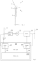
- FIG. 1 illustrates, in a schematic perspective view, an example of a wind turbine 1.
- the wind turbine 1 includes a tower 2, a nacelle 3 disposed at the apex of the tower, and a rotor 4 operatively coupled to a generator housed inside the nacelle 3.
- the nacelle houses miscellaneous components required for converting wind energy into electrical energy and various components needed to operate, control, and optimize the performance of the wind turbine 1.
- the rotor 4 of the wind turbine includes a central hub 5 and a plurality of blades 6 that project outwardly from the central hub 5. In the illustrated embodiment, the rotor 4 includes three blades 6, but the number may vary.
- the wind turbine comprises a control system.
- the control system may be placed inside the nacelle or distributed at a number of locations inside (or externally to) the turbine and communicatively connected.
- FIG. 2 schematically illustrates an embodiment of a control system 20 together with elements of a wind turbine.
- the wind turbine comprises rotor blades 6, which are mechanically connected to an electrical generator 22 via gearbox 23. In direct drive systems, and other systems, the gearbox may not be present.
- the electrical power generated by the generator 22 is injected into a power grid 24 via an electrical converter 25.
- the electrical generator 22 and the converter 25 may be based on a full-scale converter (FSC) architecture or a doubly fed induction generator (DFIG) architecture, but other types may be used.
- FSC full-scale converter
- DFIG doubly fed induction generator
- the control system 20 comprises several elements, including at least one main controller 200 with a processor and memory so that the processor is capable of executing computing tasks based on instructions stored in the memory.
- the wind turbine controller ensures that in operation the wind turbine generates a requested power output level. This is obtained by adjusting the pitch angle and/or the power extraction of the converter.
- the control system comprises a pitch system including a pitch controller 27 using a pitch reference 28 and a power system including a power controller 29 using a power reference 26.
- the power controller controls the various electric components of the generator converter system to deliver the requested power, hereunder controls the torque of the generator that is needed to extract the requested power by the rotor from the wind.
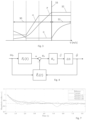
- Figure 3 illustrates a general control scheme divided into a partial load operation area 30 and a full load operation area 31.
- the wind turbine controller may adjust the pitch ( ⁇ ) of the blades to an optimal pitch angle, typically around zero degrees. This ensures that while the wind turbine is not producing the maximum amount of electricity it is able to produce it is controlled to capture as much energy from the wind as it can. If there is sufficient energy in the wind (i.e. the wind speed is above the rated wind speed 33) the wind turbine will operate in full load operation 31 while generating rated power 32, and control of the wind turbine blade pitch is used to turn the blades out of the wind to avoid overspeed of the generator and/or unsafe operation of the turbine while keeping the rotor speed constant.
- the figure moreover shows rotor speed ( ⁇ ) and generated power (P).
- the turbine While operating in the partial load region 30, the turbine may be controlled based on a tip-speed ratio (TSR) tracking scheme, which based on an estimated wind speed, determines a power setpoint P.
- the estimated wind speed being determined based on a power or torque balance between the aerodynamic power or torque of the rotor and the electrical power or torque of the generator.
- the TSR tracking scheme ensures operation in accordance with an operating power coefficient. It is important that the operating power coefficient closely matches the real power coefficient of the wind turbine. To ensure this, the operating power coefficient may be adjusted in an adjustment process in accordance with embodiments of the present invention.
- Figure 4 illustrates in a schematic manner elements of a wind speed estimator based on a power or torque balance between the aerodynamic power or torque of the rotor and the electrical power or torque of the generator.
- the actual rotor speed ( ⁇ r ) is measured by a rotor speed sensor and input into a computing block which determines the operating rotor power P r ( t ) as a sum of the power setpoint, Pg, and the power obtained from the rotor inertia.
- PI proportional-integral
- the adjustment process relies on the determination of a transfer function from a time-varying perturbation signal to a power error and the evaluation of the frequency response of the transfer function.
- a transfer function from a time-varying perturbation signal to a power error
- the evaluation of the frequency response of the transfer function is provided. It is to be understood that other transfer functions and frequency evaluations may be made not relying on the exact mathematical approach provided.
- the predetermined power coefficient may be the design power coefficient or a power coefficient which have already been adjusted, e.g. in connection with an earlier process in accordance with the present invention or by another adjustment process.
- the frequency response of the transfer function over a time period can be determined to determine the scaling factor, which minimizes the gain of the transfer function.
- the operating power coefficient is set as the scaled power coefficient.
- the frequency response evaluation can be obtained in accordance with the following example evaluation.
- the closed-loop transfer function H(s) possesses a DC gain term as the difference between the actual and estimated partial derivative of the rotor power with respect to the rotor speed (respectively indicated by Q and Q ⁇ ).
- the difference between those terms and, in turn, the magnitude of the frequency response of H ( s ) nullify whenever the turbine model information matches with the actual aerodynamic properties.
- the sign of the transfer flips whenever degradation is under- or overestimated.
- the transfer function is convex, which is further elaborated on in the following.
- a convex minimization problem may be defined so that the minimization of the gain of the transfer function is done in a convex minimization of the difference between the derivative of the predetermined power coefficient and the derivative of the scaled power coefficient.
- the first term consists out of characteristic turbine properties as a function of the turbine operational state and environmental conditions, whereas the second term contains corresponding modelled and estimated representations.
- the minimization is underdetermined, and one may take into account the following additional observations in solving the minimization problem:
- the estimated degradation function may be defined as a multiplication between an a priori known degradation profile ⁇ ( ⁇ ) and its unknown scaling factor ⁇ .
- the adjustment process may be implemented as a learning algorithm taking the convex dynamic properties of the turbine control scheme into account.
- An important advantage is that there is no need for a wind speed measurement.
- One goal of the algorithm is to correct the wind speed estimator internal model in terms of the power coefficient information.
- Embodiments of the present invention have been simulated on the NREL 5-MW reference wind turbine. Simulations obtained on the NREL reference wind turbine is known and available to the skilled person.
- the NREL reference wind turbine is for example described in the Technical Report NREL/TP-500-38060 from February 2009 by J. Jonkman, S. Butterfield, W. Musial, and G. Scot entitled "Definition of a 5-MW Reference Wind Turbine for Offshore System Development ".
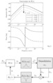
- the effect of model uncertainty on H ( s ) may be exemplified.
- the resulting steady-state operating points are obtained for each uncertainty level and are used for the evaluation of H(s).
- Figure 5 illustrates a Bode plot of the transfer function H(s) from the perturbation signal to a power error evaluated at the above-given uncertainty levels.
- the time-varying perturbation signal comprises an excitation frequency, and the frequency response is evaluated by varying the excitation frequency.
- the power error may be demodulated and numerically integrated to determine the scaling factor.
- Figure 6 illustrates a block diagram of an adjustment process in the form of a learning scheme to minimize a periodic excitation signal present in the output e P in the form of an excitation-demodulation based learning approach.
- the scheme shows that by periodically exciting P g,e with a single sinusoid at frequency ⁇ L , the output signal e P is subsequently filtered, demodulated and numerically integrated.
- N 1 s ⁇ L E P s
- E P N 1 s K s s 2 + 2 ⁇ 1 ⁇ L s + ⁇ L 2 ,
- the scaling factor ⁇ is a direct calibration parameter into the nonlinear closed-loop system to the estimated degradation function. Because of the convex and sign-altering properties of the transfer function, the above-described learning scheme converges.
- Figure 7 shows a simulation for several runs of the adjustment progress for different wind profiles to obtain the scaling factor of the power coefficient.
- the simulations are based on the NREL 5-MW reference turbine.
- the scheme is seen to converge to the exact degradation magnitude correction factor.
- the algorithm is also shown to (on average) converge to the correct value.
- the simulations are run for an extended period of time to indicate convergence, the algorithm is seen to converge on a time scale of hours.
- the algorithm shows to accurately find the actual degradation factor, whereas for the different turbulent wind realizations the degradation magnitude is found correctly on average but is subject to variational uncertainty. It is also recognized that the speed of the algorithm is on the time scale of hours, which makes the learning scheme most suitable for learning long-term degradation scenarios such as leading-edge erosion.
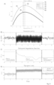
- Figure 8 illustrates simulations of generator power, scaling factor and tip-speed ratio for different power coefficients.
- the simulation is based on the based on the NREL 5-MW reference wind turbine using a low turbulence level of 3%.
- Figure 8A illustrates different power coefficients as function of tip-speed ratio.
- the power coefficient marked 81 is the predetermined or design power coefficient.
- the maximum of this power coefficient is marked with 82.
- the simulated actual power coefficient 83 is shown to be overlayed together with the resultant estimated power coefficient 84.
- the maximum of the resultant estimated power coefficient is marked with 85.
- FIGS 8B to 8D illustrate three subplots: turbine-generated power 8B, the learned correction factor of the algorithm 8C, and the tip-speed ratio (actual + controller reference) (TSR) 8D.
- the total simulation time is 8 hours, split into 3 stages:
- phase 1 in phase 1 the actual TSR is in mean somewhat lower than the reference TSR. But after the learning phase, in phase 3, the actual TSR has converged to the TSR control reference. The turbine will after the adjustment process follow the intended control TSR reference. In this manner the mismatch between the design TSR and the actual TSR is removed leading to wind turbine which will operate closer to as expected and therefore more stable.
- phase 2 the TSR setpoint has been relocated to 9.5.
- the learning scheme will work better as otherwise the time-varying perturbation signal to the power setpoint will not have a large effect on the transfer function output.
Landscapes
- Engineering & Computer Science (AREA)
- Mechanical Engineering (AREA)
- Combustion & Propulsion (AREA)
- General Engineering & Computer Science (AREA)
- Sustainable Development (AREA)
- Sustainable Energy (AREA)
- Chemical & Material Sciences (AREA)
- Life Sciences & Earth Sciences (AREA)
- Physics & Mathematics (AREA)
- Fluid Mechanics (AREA)
- Evolutionary Computation (AREA)
- Artificial Intelligence (AREA)
- Fuzzy Systems (AREA)
- Mathematical Physics (AREA)
- Software Systems (AREA)
- Wind Motors (AREA)
Claims (15)
- Verfahren zum Steuern einer Windkraftanlage in einem Teillastbetriebsmodus basierend auf einem Spitzengeschwindigkeitsverhältnis-, (TSR)-Verfolgungsschema, das basierend auf einer geschätzten Windgeschwindigkeit einen Leistungssollwert bestimmt, wobei die geschätzte Windgeschwindigkeit basierend auf einem Leistungs- oder Drehmomentgleichgewicht zwischen der aerodynamischen Leistung oder dem Drehmoment des Rotors und der elektrischen Leistung oder dem Drehmoment des Generators bestimmt wird, wobei das TSR-Verfolgungsschema für einen Betrieb in Übereinstimmung mit einem Betriebsleistungskoeffizienten sorgt, und wobei der Betriebsleistungskoeffizient in einem Anpassungsprozess angepasst wurde, wobei das Verfahren dadurch gekennzeichnet ist, dass der Anpassungsprozess umfasst:Einstellen eines skalierten Leistungskoeffizienten als einen vorbestimmten Leistungskoeffizienten multipliziert mit einem Skalierungsfaktor;Hinzufügen eines zeitveränderlichen Störsignals zum Leistungssollwert;Bestimmen einer Übertragungsfunktion vom Störsignal zu einem Leistungsfehler, wobei der Leistungsfehler als die Differenz zwischen einer betrieblichen Rotorleistung und einer geschätzten Rotorleistung bestimmt wird;Auswerten des Frequenzgangs der Übertragungsfunktion über einen Zeitraum hinweg, um den Skalierungsfaktor, der die Verstärkung der Übertragungsfunktion minimiert, zu bestimmen;Einstellen des Betriebsleistungskoeffizienten als den skalierten Leistungskoeffizienten.
- Verfahren nach Anspruch 1, wobei das zeitveränderliche Störsignal eine Erregungsfrequenz umfasst, und wobei der Frequenzgang durch Verändern der Erregungsfrequenz ausgewertet wird.
- Verfahren nach Anspruch 2, wobei das zeitveränderliche Störsignal eine einzelne Sinuskurve auf der Erregungsfrequenz ist.
- Verfahren nach einem der vorstehenden Ansprüche, wobei die betriebliche Rotorleistung eine Summe aus dem Leistungssollwert und der aus der Rotorträgheit erhaltenen Leistung beinhaltet.
- Verfahren nach einem der vorstehenden Ansprüche, wobei die geschätzte Rotorleistung aus einem internen Modell der Rotorleistung basierend auf dem skalierten Leistungskoeffizienten erhalten wird.
- Verfahren nach einem der vorstehenden Ansprüche, wobei der Anpassungsprozess ein geschlossener Regelkreisprozess ist.
- Verfahren nach einem der vorstehenden Ansprüche, wobei die Minimierung der Verstärkung der Übertragungsfunktion in einer konvexen Minimierung der Differenz zwischen der Ableitung des vorbestimmten Leistungskoeffizienten und der Ableitung des skalierten Leistungskoeffizienten erfolgt.
- Verfahren nach einem der vorstehenden Ansprüche, wobei ein Leistungsfehler demoduliert und numerisch integriert wird, um den Skalierungsfaktor zu bestimmen.
- Verfahren nach einem der vorstehenden Ansprüche, wobei der Anpassungszeitraum während eines Zeitraums zwischen einer und zehn Stunden durchgeführt wird.
- Verfahren nach Anspruch 9, wobei der Zeitraum basierend auf einer Turbulenzintensität bestimmt wird, sodass der Zeitraum bei geringer Turbulenzintensität kürzer ist als bei hoher Turbulenzintensität.
- Verfahren nach einem der vorstehenden Ansprüche, wobei der Anpassungsprozess davon abhängt, dass die Turbulenzintensität unter einem vordefinierten Turbulenzintensitätsniveau liegt.
- Verfahren nach einem der vorstehenden Ansprüche, wobei die Windkraftanlage nach dem Anpassungsprozess unter Verwendung des skalierten Leistungskoeffizienten betrieben wird.
- Nichtflüchtiges computerlesbares Speichermedium, auf dem Anweisungen gespeichert sind, die, wenn sie von einem oder mehreren Prozessoren ausgeführt werden, den einen oder mehrere Prozessoren veranlassen, ein Verfahren nach einem vorstehenden Anspruch auszuführen.
- Steuereinheit zum Steuern einer Windkraftanlage in einem Teillastbetriebsmodus in Übereinstimmung mit einem der Ansprüche 1 bis 12.
- Windkraftanlage, die eine Steuereinheit nach Anspruch 14 umfasst.
Priority Applications (2)
| Application Number | Priority Date | Filing Date | Title |
|---|---|---|---|
| EP22205531.1A EP4365437B1 (de) | 2022-11-04 | 2022-11-04 | Steuerung einer windturbine mit skaliertem leistungskoeffizienten |
| US18/499,397 US12031522B2 (en) | 2022-11-04 | 2023-11-01 | Controlling a wind turbine with a scaled power coefficient |
Applications Claiming Priority (1)
| Application Number | Priority Date | Filing Date | Title |
|---|---|---|---|
| EP22205531.1A EP4365437B1 (de) | 2022-11-04 | 2022-11-04 | Steuerung einer windturbine mit skaliertem leistungskoeffizienten |
Publications (3)
| Publication Number | Publication Date |
|---|---|
| EP4365437A1 EP4365437A1 (de) | 2024-05-08 |
| EP4365437C0 EP4365437C0 (de) | 2025-05-14 |
| EP4365437B1 true EP4365437B1 (de) | 2025-05-14 |
Family
ID=84245672
Family Applications (1)
| Application Number | Title | Priority Date | Filing Date |
|---|---|---|---|
| EP22205531.1A Active EP4365437B1 (de) | 2022-11-04 | 2022-11-04 | Steuerung einer windturbine mit skaliertem leistungskoeffizienten |
Country Status (2)
| Country | Link |
|---|---|
| US (1) | US12031522B2 (de) |
| EP (1) | EP4365437B1 (de) |
Families Citing this family (1)
| Publication number | Priority date | Publication date | Assignee | Title |
|---|---|---|---|---|
| CN120292014B (zh) * | 2025-05-28 | 2025-09-05 | 内蒙古明阳北方智慧能源研发中心有限公司 | 发电风机叶尖速比寻优控制方法与系统 |
Family Cites Families (5)
| Publication number | Priority date | Publication date | Assignee | Title |
|---|---|---|---|---|
| EP2847457B1 (de) * | 2012-05-11 | 2021-10-27 | Vestas Wind Systems A/S | Stromsystem und verfahren zum betreiben einer windenergieanlage mit einem verteilungsalgorithmus |
| WO2014048583A1 (en) * | 2012-09-28 | 2014-04-03 | Siemens Aktiengesellschaft | Method and arrangement for controlling a wind turbine |
| CN105790298B (zh) * | 2014-12-23 | 2019-03-12 | 台达电子工业股份有限公司 | 风力发电控制装置及风力发电系统 |
| EP3088733B1 (de) * | 2015-04-27 | 2018-10-17 | Envision Energy (Jiangsu) Co., Ltd. | Verfahren zum Betrieb einer Windturbine auf Grundlage des Verschleisses der Windturbinenschaufel |
| US9816487B2 (en) * | 2015-09-23 | 2017-11-14 | Bala Govind | System and method for integrating a horizontal axis wind turbine and a vertical axis wind turbine |
-
2022
- 2022-11-04 EP EP22205531.1A patent/EP4365437B1/de active Active
-
2023
- 2023-11-01 US US18/499,397 patent/US12031522B2/en active Active
Also Published As
| Publication number | Publication date |
|---|---|
| US12031522B2 (en) | 2024-07-09 |
| US20240159216A1 (en) | 2024-05-16 |
| EP4365437A1 (de) | 2024-05-08 |
| EP4365437C0 (de) | 2025-05-14 |
Similar Documents
| Publication | Publication Date | Title |
|---|---|---|
| EP2115299B1 (de) | Windturbinendämpfung einer turmresonanzbewegung und symmetrischen schaufelbewegung unter verwendung von schätzungsverfahren | |
| Bossanyi et al. | Validation of individual pitch control by field tests on two-and three-bladed wind turbines | |
| Badihi et al. | Fuzzy gain-scheduled active fault-tolerant control of a wind turbine | |
| Taveiros et al. | Back-to-back converter state-feedback control of DFIG (doubly-fed induction generator)-based wind turbines | |
| CN100593641C (zh) | 变桨距风力发电系统的逆系统鲁棒控制方法 | |
| CN102588211B (zh) | 一种风力发电机组全工况模型预测控制方法及系统 | |
| CN106981878A (zh) | 一种基于自抗扰控制的双馈风机抑制电网低频振荡的方法 | |
| CN103758699B (zh) | 一种风力发电机组的桨距角控制方法及桨距角控制器 | |
| US11522479B2 (en) | Method and system of subsynchronous oscillations and interactions damping | |
| CN109416523A (zh) | 在低电压电网事件期间使用mpc控制风力涡轮机 | |
| EP4162160B1 (de) | Temperaturschätzung in einer windturbine | |
| US12031522B2 (en) | Controlling a wind turbine with a scaled power coefficient | |
| Itouchene et al. | Enhancing the performance of grid-connected DFIG systems using prescribed convergence law | |
| Requate et al. | Active control of the reliability of wind turbines | |
| JP2006037850A (ja) | 風力発電機のピッチ角制御装置 | |
| CN116845886A (zh) | 一种基于模型预测的多端口自主光伏系统构网型控制方法 | |
| Jia et al. | Linear active disturbance rejection control for large onshore wind turbines in full wind speed range | |
| Freeman et al. | Direct model-reference adaptive control of variable speed horizontal-axis wind turbines | |
| Hackl et al. | Non-ideal feedforward torque control of wind turbines: Impacts on annual energy production & gross earnings | |
| Jasniewicz et al. | Wind turbine modelling and identification for control system applications | |
| EP4386201B1 (de) | Steuerung einer windturbine mit anhand einer degradationsfunktion eingestelltem aktualisierten leistungskoeffizienten | |
| Aslmostafa et al. | Robust control strategies for floating wind turbines: preliminary experimental results | |
| Devi et al. | Modelling and Performance Analysis of DFIG Integrated with LMF-PLL under Grid Abnormalities | |
| Wu et al. | Nacelle anemometer measurement‐based extremum‐seeking wind turbine region‐2 control for improved convergence in fluctuating wind | |
| Mseddi et al. | HESG based WECS Overview, modeling, and fractional order control |
Legal Events
| Date | Code | Title | Description |
|---|---|---|---|
| PUAI | Public reference made under article 153(3) epc to a published international application that has entered the european phase |
Free format text: ORIGINAL CODE: 0009012 |
|
| STAA | Information on the status of an ep patent application or granted ep patent |
Free format text: STATUS: THE APPLICATION HAS BEEN PUBLISHED |
|
| AK | Designated contracting states |
Kind code of ref document: A1 Designated state(s): AL AT BE BG CH CY CZ DE DK EE ES FI FR GB GR HR HU IE IS IT LI LT LU LV MC ME MK MT NL NO PL PT RO RS SE SI SK SM TR |
|
| STAA | Information on the status of an ep patent application or granted ep patent |
Free format text: STATUS: REQUEST FOR EXAMINATION WAS MADE |
|
| 17P | Request for examination filed |
Effective date: 20241104 |
|
| RBV | Designated contracting states (corrected) |
Designated state(s): AL AT BE BG CH CY CZ DE DK EE ES FI FR GB GR HR HU IE IS IT LI LT LU LV MC ME MK MT NL NO PL PT RO RS SE SI SK SM TR |
|
| GRAP | Despatch of communication of intention to grant a patent |
Free format text: ORIGINAL CODE: EPIDOSNIGR1 |
|
| STAA | Information on the status of an ep patent application or granted ep patent |
Free format text: STATUS: GRANT OF PATENT IS INTENDED |
|
| INTG | Intention to grant announced |
Effective date: 20250303 |
|
| GRAS | Grant fee paid |
Free format text: ORIGINAL CODE: EPIDOSNIGR3 |
|
| GRAA | (expected) grant |
Free format text: ORIGINAL CODE: 0009210 |
|
| STAA | Information on the status of an ep patent application or granted ep patent |
Free format text: STATUS: THE PATENT HAS BEEN GRANTED |
|
| AK | Designated contracting states |
Kind code of ref document: B1 Designated state(s): AL AT BE BG CH CY CZ DE DK EE ES FI FR GB GR HR HU IE IS IT LI LT LU LV MC ME MK MT NL NO PL PT RO RS SE SI SK SM TR |
|
| REG | Reference to a national code |
Ref country code: GB Ref legal event code: FG4D |
|
| REG | Reference to a national code |
Ref country code: CH Ref legal event code: EP |
|
| REG | Reference to a national code |
Ref country code: DE Ref legal event code: R096 Ref document number: 602022014598 Country of ref document: DE |
|
| REG | Reference to a national code |
Ref country code: IE Ref legal event code: FG4D |
|
| U01 | Request for unitary effect filed |
Effective date: 20250526 |
|
| U07 | Unitary effect registered |
Designated state(s): AT BE BG DE DK EE FI FR IT LT LU LV MT NL PT RO SE SI Effective date: 20250603 |
|
| PG25 | Lapsed in a contracting state [announced via postgrant information from national office to epo] |
Ref country code: ES Free format text: LAPSE BECAUSE OF FAILURE TO SUBMIT A TRANSLATION OF THE DESCRIPTION OR TO PAY THE FEE WITHIN THE PRESCRIBED TIME-LIMIT Effective date: 20250514 |
|
| PG25 | Lapsed in a contracting state [announced via postgrant information from national office to epo] |
Ref country code: NO Free format text: LAPSE BECAUSE OF FAILURE TO SUBMIT A TRANSLATION OF THE DESCRIPTION OR TO PAY THE FEE WITHIN THE PRESCRIBED TIME-LIMIT Effective date: 20250814 Ref country code: GR Free format text: LAPSE BECAUSE OF FAILURE TO SUBMIT A TRANSLATION OF THE DESCRIPTION OR TO PAY THE FEE WITHIN THE PRESCRIBED TIME-LIMIT Effective date: 20250815 |
|
| PG25 | Lapsed in a contracting state [announced via postgrant information from national office to epo] |
Ref country code: PL Free format text: LAPSE BECAUSE OF FAILURE TO SUBMIT A TRANSLATION OF THE DESCRIPTION OR TO PAY THE FEE WITHIN THE PRESCRIBED TIME-LIMIT Effective date: 20250514 |
|
| PG25 | Lapsed in a contracting state [announced via postgrant information from national office to epo] |
Ref country code: HR Free format text: LAPSE BECAUSE OF FAILURE TO SUBMIT A TRANSLATION OF THE DESCRIPTION OR TO PAY THE FEE WITHIN THE PRESCRIBED TIME-LIMIT Effective date: 20250514 |
|
| PG25 | Lapsed in a contracting state [announced via postgrant information from national office to epo] |
Ref country code: RS Free format text: LAPSE BECAUSE OF FAILURE TO SUBMIT A TRANSLATION OF THE DESCRIPTION OR TO PAY THE FEE WITHIN THE PRESCRIBED TIME-LIMIT Effective date: 20250814 |
|
| PG25 | Lapsed in a contracting state [announced via postgrant information from national office to epo] |
Ref country code: IS Free format text: LAPSE BECAUSE OF FAILURE TO SUBMIT A TRANSLATION OF THE DESCRIPTION OR TO PAY THE FEE WITHIN THE PRESCRIBED TIME-LIMIT Effective date: 20250914 |
|
| U20 | Renewal fee for the european patent with unitary effect paid |
Year of fee payment: 4 Effective date: 20251126 |
|
| PG25 | Lapsed in a contracting state [announced via postgrant information from national office to epo] |
Ref country code: SM Free format text: LAPSE BECAUSE OF FAILURE TO SUBMIT A TRANSLATION OF THE DESCRIPTION OR TO PAY THE FEE WITHIN THE PRESCRIBED TIME-LIMIT Effective date: 20250514 |
|
| PG25 | Lapsed in a contracting state [announced via postgrant information from national office to epo] |
Ref country code: CZ Free format text: LAPSE BECAUSE OF FAILURE TO SUBMIT A TRANSLATION OF THE DESCRIPTION OR TO PAY THE FEE WITHIN THE PRESCRIBED TIME-LIMIT Effective date: 20250514 |
|
| PG25 | Lapsed in a contracting state [announced via postgrant information from national office to epo] |
Ref country code: SK Free format text: LAPSE BECAUSE OF FAILURE TO SUBMIT A TRANSLATION OF THE DESCRIPTION OR TO PAY THE FEE WITHIN THE PRESCRIBED TIME-LIMIT Effective date: 20250514 |
|
| PLBE | No opposition filed within time limit |
Free format text: ORIGINAL CODE: 0009261 |
|
| STAA | Information on the status of an ep patent application or granted ep patent |
Free format text: STATUS: NO OPPOSITION FILED WITHIN TIME LIMIT |
|
| REG | Reference to a national code |
Ref country code: CH Ref legal event code: L10 Free format text: ST27 STATUS EVENT CODE: U-0-0-L10-L00 (AS PROVIDED BY THE NATIONAL OFFICE) Effective date: 20260325 |
|
| 26N | No opposition filed |
Effective date: 20260217 |