EP4386123A1 - Household appliance featuring a water softening system and method of operating such a household appliance - Google Patents
Household appliance featuring a water softening system and method of operating such a household appliance Download PDFInfo
- Publication number
- EP4386123A1 EP4386123A1 EP22213628.5A EP22213628A EP4386123A1 EP 4386123 A1 EP4386123 A1 EP 4386123A1 EP 22213628 A EP22213628 A EP 22213628A EP 4386123 A1 EP4386123 A1 EP 4386123A1
- Authority
- EP
- European Patent Office
- Prior art keywords
- brine
- household appliance
- salt container
- level
- container
- Prior art date
- Legal status (The legal status is an assumption and is not a legal conclusion. Google has not performed a legal analysis and makes no representation as to the accuracy of the status listed.)
- Pending
Links
Images



Classifications
-
- D—TEXTILES; PAPER
- D06—TREATMENT OF TEXTILES OR THE LIKE; LAUNDERING; FLEXIBLE MATERIALS NOT OTHERWISE PROVIDED FOR
- D06F—LAUNDERING, DRYING, IRONING, PRESSING OR FOLDING TEXTILE ARTICLES
- D06F39/00—Details of washing machines not specific to a single type of machines covered by groups D06F9/00 - D06F27/00
- D06F39/007—Arrangements of water softeners
-
- D—TEXTILES; PAPER
- D06—TREATMENT OF TEXTILES OR THE LIKE; LAUNDERING; FLEXIBLE MATERIALS NOT OTHERWISE PROVIDED FOR
- D06F—LAUNDERING, DRYING, IRONING, PRESSING OR FOLDING TEXTILE ARTICLES
- D06F33/00—Control of operations performed in washing machines or washer-dryers
- D06F33/30—Control of washing machines characterised by the purpose or target of the control
- D06F33/32—Control of operational steps, e.g. optimisation or improvement of operational steps depending on the condition of the laundry
-
- D—TEXTILES; PAPER
- D06—TREATMENT OF TEXTILES OR THE LIKE; LAUNDERING; FLEXIBLE MATERIALS NOT OTHERWISE PROVIDED FOR
- D06F—LAUNDERING, DRYING, IRONING, PRESSING OR FOLDING TEXTILE ARTICLES
- D06F33/00—Control of operations performed in washing machines or washer-dryers
- D06F33/30—Control of washing machines characterised by the purpose or target of the control
- D06F33/32—Control of operational steps, e.g. optimisation or improvement of operational steps depending on the condition of the laundry
- D06F33/37—Control of operational steps, e.g. optimisation or improvement of operational steps depending on the condition of the laundry of metering of detergents or additives
-
- D—TEXTILES; PAPER
- D06—TREATMENT OF TEXTILES OR THE LIKE; LAUNDERING; FLEXIBLE MATERIALS NOT OTHERWISE PROVIDED FOR
- D06F—LAUNDERING, DRYING, IRONING, PRESSING OR FOLDING TEXTILE ARTICLES
- D06F34/00—Details of control systems for washing machines, washer-dryers or laundry dryers
- D06F34/04—Signal transfer or data transmission arrangements
- D06F34/05—Signal transfer or data transmission arrangements for wireless communication between components, e.g. for remote monitoring or control
-
- D—TEXTILES; PAPER
- D06—TREATMENT OF TEXTILES OR THE LIKE; LAUNDERING; FLEXIBLE MATERIALS NOT OTHERWISE PROVIDED FOR
- D06F—LAUNDERING, DRYING, IRONING, PRESSING OR FOLDING TEXTILE ARTICLES
- D06F34/00—Details of control systems for washing machines, washer-dryers or laundry dryers
- D06F34/14—Arrangements for detecting or measuring specific parameters
-
- D—TEXTILES; PAPER
- D06—TREATMENT OF TEXTILES OR THE LIKE; LAUNDERING; FLEXIBLE MATERIALS NOT OTHERWISE PROVIDED FOR
- D06F—LAUNDERING, DRYING, IRONING, PRESSING OR FOLDING TEXTILE ARTICLES
- D06F2103/00—Parameters monitored or detected for the control of domestic laundry washing machines, washer-dryers or laundry dryers
-
- D—TEXTILES; PAPER
- D06—TREATMENT OF TEXTILES OR THE LIKE; LAUNDERING; FLEXIBLE MATERIALS NOT OTHERWISE PROVIDED FOR
- D06F—LAUNDERING, DRYING, IRONING, PRESSING OR FOLDING TEXTILE ARTICLES
- D06F2103/00—Parameters monitored or detected for the control of domestic laundry washing machines, washer-dryers or laundry dryers
- D06F2103/20—Washing liquid condition, e.g. turbidity
-
- D—TEXTILES; PAPER
- D06—TREATMENT OF TEXTILES OR THE LIKE; LAUNDERING; FLEXIBLE MATERIALS NOT OTHERWISE PROVIDED FOR
- D06F—LAUNDERING, DRYING, IRONING, PRESSING OR FOLDING TEXTILE ARTICLES
- D06F2105/00—Systems or parameters controlled or affected by the control systems of washing machines, washer-dryers or laundry dryers
- D06F2105/08—Draining of washing liquids
-
- D—TEXTILES; PAPER
- D06—TREATMENT OF TEXTILES OR THE LIKE; LAUNDERING; FLEXIBLE MATERIALS NOT OTHERWISE PROVIDED FOR
- D06F—LAUNDERING, DRYING, IRONING, PRESSING OR FOLDING TEXTILE ARTICLES
- D06F2105/00—Systems or parameters controlled or affected by the control systems of washing machines, washer-dryers or laundry dryers
- D06F2105/58—Indications or alarms to the control system or to the user
-
- D—TEXTILES; PAPER
- D06—TREATMENT OF TEXTILES OR THE LIKE; LAUNDERING; FLEXIBLE MATERIALS NOT OTHERWISE PROVIDED FOR
- D06F—LAUNDERING, DRYING, IRONING, PRESSING OR FOLDING TEXTILE ARTICLES
- D06F34/00—Details of control systems for washing machines, washer-dryers or laundry dryers
- D06F34/14—Arrangements for detecting or measuring specific parameters
- D06F34/20—Parameters relating to constructional components, e.g. door sensors
-
- D—TEXTILES; PAPER
- D06—TREATMENT OF TEXTILES OR THE LIKE; LAUNDERING; FLEXIBLE MATERIALS NOT OTHERWISE PROVIDED FOR
- D06F—LAUNDERING, DRYING, IRONING, PRESSING OR FOLDING TEXTILE ARTICLES
- D06F34/00—Details of control systems for washing machines, washer-dryers or laundry dryers
- D06F34/14—Arrangements for detecting or measuring specific parameters
- D06F34/22—Condition of the washing liquid, e.g. turbidity
Definitions
- the present disclosure generally relates to the field of laundry treatment appliances (hereinafter, concisely, "household appliances”), and particularly to household appliances for treating (e.g ., washing) laundry, such as laundry washing appliances and laundry washing appliances also implementing laundry drying functions (also referred to as washers/dryers), comprising a water softening system.
- household appliances for treating (e.g ., washing) laundry such as laundry washing appliances and laundry washing appliances also implementing laundry drying functions (also referred to as washers/dryers), comprising a water softening system.
- a conventional household appliance is configured to treat laundry located in a (e.g ., rotatable) drum by providing process liquids in a washing tub housing the rotatable drum.
- Process liquids may comprise ( e.g ., depending on a selected treatment cycle and/or on a current phase of the selected treatment cycle) plain water or a treatment mixture comprising water mixed with proper treatment agents, including, but not limited to, washing detergents, rinsing detergents, bleaches and softeners detergents.
- a modern type of household appliance comprises a water softening system configured to receive fresh water and to provide a softened water having a reduced hardness than the fresh water.
- the water softening system comprises a water softening agent container configured to store a water softening agent (such as an ion-exchange resin) capable of reducing the hardness of the fresh water by reaction of the fresh water with the water softening agent.
- a water softening agent such as an ion-exchange resin
- the water softening system comprises a salt container configured to store salt, which is used for regenerating the water softening agent contained in the water softening agent container during a water softening agent regeneration procedure.
- the salt container is configured to receive the fresh water, generate a mixture of salt and fresh water to produce a brine, and channel the brine into the water softening agent container to allow regeneration of the water softening agent.
- the salt container is removably accommodated within the household appliance, so as to allow a user to refill it with new amounts of salt.
- the Applicant has realized that the current household appliances provided with the water softening system are not satisfactory.
- this is essentially due to the fact that it is up to the user to manually determine a salt level within the salt container, usually by visual inspection and/or subjective estimation.
- indicator sticks similar to rulers, with reference marks to aid the user in judging a depth of the salt within the salt container, is also inaccurate. Indeed, while the brine is being generated, the salt continuously dissolves and redeposits due to chemical equilibrium reactions. During salt deposition, salt bridges may form which may change an appearance of salt volume within the salt container.
- Last but not least, visual inspection and/or subjective estimation to determine the salt level within the salt container, as well as refilling of salt, is performed by extracting the salt container from the household appliance, or from the drawer wherein the salt container is arranged.
- EP3221501 B1 discloses a washing machine with a main drawer which is fitted/ inserted in extractable manner into a corresponding substantially basin-shaped drawer housing arranged in the upper portion of the casing of the washing machine, and a water softening device comprising a manually fillable regeneration-agent compartment arranged in the a main drawer, and a brine container located underneath the drawer housing and communicating with the bottom of the drawer housing so as to allow the brine formed in the regeneration-agent compartment to freely flow by gravity from a basin-shaped bottom portion of said drawer housing into the same brine container, so that the regeneration-agent compartment remains empty after brine has formed.
- the Applicant has devised a household appliance that is not affected by the above-mentioned drawbacks, and particularly a household appliance capable of automatically detecting a salinity level of the brine inside the salt container, and draining the brine from the salt container when the salinity level of the brine is below a threshold salinity level.
- An aspect of the present disclosure relates to a household appliance.
- the household appliance comprises a water softening system configured to receive fresh water having a first level of hardness and to provide softened water having a second level of hardness lower than the first level of hardness.
- the water softening system comprises a water softening agent container configured to store a water softening agent capable of reducing a hardness of the fresh water.
- the water softening system comprises a salt container, removably accommodated within the household appliance and hydraulically connected to the water softening agent container when accommodated within the household appliance.
- the salt container is hydraulically connected to a water supply unit when accommodated within the household appliance.
- the salt container is hydraulically connected to a draining arrangement when accommodated within the household appliance.
- the salt container is configured to allow air to exit the salt container (air venting) when accommodated within the household appliance.
- the hydraulic connection between the salt container and the water softening agent container, the hydraulic connection between the salt container and the water supply unit, and the exit of air from the salt container are obtained each one by means of respective one or more check valves.
- each pair of check valves comprises a check valve integral with (e.g., housed in) the salt container, and one or more check valves integral with ( e.g ., housed in) a fixed portion of the water softening system or of the household appliance (the salt container being movable with respect to said fixed portion).
- the pairs of check valves when the salt container is inserted within the household appliance, the pairs of check valves are open (due to interaction or cooperation of the check valves of each pair), thereby allowing said hydraulic connections of the salt container and said exit of air, whereas when the salt container is extracted from the household appliance, the pairs of check valve are closed (due to interaction or cooperation loss between the check valves of each pair), thereby preventing said hydraulic connections of the salt container and said exit of air.
- the salt container is configured to receive the fresh water, generate a mixture of salt and fresh water to produce a brine, and channel the brine into the water softening agent container to allow a regeneration of the water softening agent.
- the water softening system comprises a draining arrangement hydraulically connected to the salt container, and configured to drain the brine from the salt container.
- the draining arrangement is configured to drain the brine from the salt container into a drain through a washing tub of the household appliance ( i.e., by bypassing a process liquid supply apparatus configured to supply process liquids into the washing tub and comprising, for example, a drawer). This avoids that the process liquid supply apparatus gets soiled with the brine and/or impurities thereof.
- the draining arrangement may be configured to drain the brine from the salt container into the drain by bypassing both the process liquid supply apparatus and the washing tub. This avoids that both the process liquid supply apparatus and the washing tub get soiled with the brine and/or impurities thereof.
- the draining arrangement may be configured to drain the brine from the salt container into the drain through the process liquid supply apparatus and the washing tub.
- dedicated channels within the process liquid supply apparatus may be provided for channelling the brine to be discharged.
- the brine contained in the salt container is channelled into the water softening agent container by the pressure of the fresh water entering the salt container.
- the draining arrangement may be configured to drain the brine from the salt container and to supply the brine to the water softening agent container.
- the draining arrangement may be configured to be switched ( e.g ., under the control of the control unit) into first or second active states allowing the brine to be fed from the salt container to the drain or to the water softening agent container, respectively, or into an inactive state preventing the brine from exiting the salt container.
- a dedicated draining arrangement (other than the draining arrangement) may be provided to drain the brine from the salt container and to supply the brine to the water softening agent container.
- the water softening system comprises a salinity detection unit for detecting a salinity level of the brine inside the salt container.
- the water softening system comprises a control unit configured to activate the draining arrangement to cause the brine to be drained from the salt container when the salinity detection unit detects that the salinity level of the brine is below a threshold salinity level.
- the water softening system further comprises a presence detection unit for detecting a presence or absence of the salt container within the household appliance.
- control unit is configured to activate the draining arrangement to cause the brine to be drained from the salt container when the presence detection unit detects the presence of the salt container within the household appliance, and/or when the salinity detection unit detects that the salinity level of the brine is below a threshold salinity level.
- the water softening system comprises a brine level detection unit for detecting a brine level in the salt container.
- control unit is configured to activate the draining arrangement to cause the brine to be drained from the salt container when the brine level detection unit detects that the brine level in the salt container is above a threshold brine level and when the salinity detection unit detects that the salinity level of the brine is below a threshold salinity level.
- the presence detection unit may be omitted in this embodiment.
- control unit is configured to activate the draining arrangement to cause the brine to be drained from the salt container when the salinity detection unit detects that the salinity level of the brine is below a threshold salinity level, the brine level detection unit detects that the brine level in the salt container is above a threshold brine level and the presence detection unit detects the presence of the salt container within the household appliance.
- the household appliance comprises warning means configured to communicate with the control unit.
- the warning means is configured to provide one or more warning indications to the user.
- the warning means comprises one or more warning units of a physical user interface of the household appliance.
- the warning means comprises one or more warning functions associated with a virtual user interface of the household appliance.
- the virtual user interface may be provided by a mobile application running on an external device (such as a personal digital assistant (PDA), a smartphone, a tablet, a wearable smart device (such as a smartwatch) external to the household appliance and communicably coupled thereto ( e.g ., through a wireless communication link).
- PDA personal digital assistant
- a smartphone such as a smartphone, a tablet, a wearable smart device (such as a smartwatch) external to the household appliance and communicably coupled thereto (e.g ., through a wireless communication link).
- PDA personal digital assistant
- a smartphone such as a smartphone, a tablet, a wearable smart device (such as a smartwatch) external to the household appliance and communicably coupled thereto (e.g ., through a wireless communication link).
- a wearable smart device such as a smartwatch
- the warning function(s) may comprise a notification on the external device.
- the notification may for example be a push notification, such as a banner on the top of the device screen and/or dialog box that interrupts and blocks the view of any running application, and may contain text and/or vocal and/or image message (possibly with the further playing of an alert sound to attract the attention of the user).
- control unit is configured to provide a signal indicative of an empty or substantially empty condition of the salt container once the brine has been drained from the salt container by the draining arrangement, and to activate the warning means to inform a user that the salt container can be extracted from the household appliance to be refilled with salt.
- the empty or substantially empty condition of the salt container is checked based on the brine level detection signals from the brine level detection unit. Additionally, or alternatively, the empty or substantially empty condition of the salt container is checked based on a predefined time interval deemed necessary to achieve the empty or substantially empty condition.
- the brine level detection unit may be omitted, and the brine may be assumed to be drained from the salt container upon elapsing of the predefined time interval from activation of the draining arrangement.
- the water softening system comprises a housing for removably accommodating the salt container therein.
- the housing represents said fixed portion of the water softening system or of the household appliance (the salt container being movable with respect to said housing).
- the housing is hydraulically connected to the salt container and to the draining arrangement.
- the salinity detection unit is arranged in the housing. According to an alternative embodiment, the salinity detection unit is arranged outside the housing.
- the presence detection unit (when provided) is arranged in the housing. According to an alternative embodiment, the presence detection unit (when provided) is arranged outside the housing.
- the brine level detection unit (when provided) is arranged in the housing. According to an alternative embodiment, the brine level detection unit when provided) is arranged outside the housing.
- the household appliance comprises a processing unit for receiving salinity detection signals from the salinity detection unit, and for providing to the control unit an indication of the salinity level of the brine contained in the salt container.
- the processing unit may be omitted in basic embodiments.
- the salinity detection unit may be electrically connected (e.g ., directly) to the control unit.
- the salinity detection unit may transmit the salinity detection signals to the control unit, and the control unit may determine an indication of the salinity level of the brine contained in the salt container based on the received salinity detection signals.
- the processing unit (when provided) is arranged in the housing. According to an alternative embodiment, the processing unit (when provided) is arranged outside the housing.
- the housing comprises a receiving portion for receiving the processing unit.
- the processing unit is configured to receive presence detection signals from the presence detection unit, and to provide to the control unit an indication of the presence of the salt container within the household appliance.
- the presence detection unit (when provided) may be electrically connected ( e.g ., directly) to the control unit.
- the presence detection unit may transmit the presence detection signals to the control unit, and the control unit may determine an indication of the presence or absence of the salt container within the household appliance based on the received presence detection signals.
- the processing unit is configured to receive brine level detection signals from the brine level detection unit, and to provide to the control unit an indication of the brine level in the salt container.
- the brine level detection unit (when provided) may be electrically connected ( e.g ., directly) to the control unit.
- the brine level detection unit may transmit the brine level detection signals to the control unit, and the control unit may determine an indication of the brine level in the salt container based on the received brine level detection signals.
- the draining arrangement comprises a draining pump.
- the housing comprises a seat for accommodating the draining pump (or, more generally, the draining arrangement) therein.
- the draining pump (or, more generally, the draining arrangement) is arranged outside the housing.
- the housing comprises a first housing shell and a second housing shell connected to each other in a removable manner.
- the housing is adapted to be fixed to the household appliance.
- the housing is adapted to be fixed to the household appliance (such as to the basement portion thereof) by means of a fixing arrangement. Additionally or alternatively, the housing is adapted to be fixed to the household appliance (such as to the basement portion thereof) by frictional engagement between the housing (e.g ., the first or second housing shell thereof) and a housing seat formed in the household appliance (such as a housing seat formed in the basement portion thereof).
- Another aspect of the present disclosure relates to a method of operating a household appliance comprising a water softening agent container configured to store a water softening agent capable of reducing a hardness of fresh water, and a salt container configured to receive the fresh water, generate a mixture of salt and fresh water to produce a brine, and channel the brine into the water softening agent container to allow a regeneration of the water softening agent.
- the method comprises detecting a salinity level of the brine inside the salt container.
- the method comprises, when the salinity level of the brine is below a threshold salinity level, activating a draining arrangement hydraulically connected to the salt container, to cause the brine to be drained from the salt container.
- the method comprises, when the salinity level of the brine is above the threshold salinity level, outputting a message indicative of an adequate salinity level.
- the method comprises, if the brine level is below the threshold brine level, outputting a corresponding error message. According an alternative embodiment, if the brine level is below the threshold brine level, no further actions are performed.
- the method comprises checking a presence or absence of the salt container within the household appliance.
- the method comprises activating the draining arrangement to cause the brine to be drained from the salt container if the salinity level of the brine is below the threshold salinity level and if the salt container is present within the household appliance.
- the method comprises checking the presence of the salt container within the household appliance, and checking the salinity level of the brine within the salt container if the salt container is present within the household appliance.
- the salinity level of the brine within the salt container may be checked without any previous salt container presence checking. Without losing generality, the salt container presence checking may be performed and/or repeated at any suitable phase of the method.
- the method comprises checking the presence of the salt container within the household appliance, performing a water softening agent regeneration procedure if the salt container is present within the household appliance, and checking the salinity level of the brine within the salt container after the water softening agent regeneration procedure.
- the water softening agent regeneration procedure may be omitted, the water softening agent regeneration procedure being for example performed after a treatment cycle end and before the method is run.
- the method ends.
- a message indicative of the absence of the salt container may be output for the user.
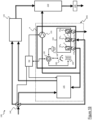
- Figures 1A and 1B show a perspective view of a household appliance 100 and a hydraulic/electric circuit thereof, respectively, according to an exemplary embodiment of the present disclosure.
- appliance components deemed relevant for the understanding of the exemplary embodiment of the present disclosure will be discussed for the sake of conciseness.
- directional terminology (such as above, below, front, rear, central, side, upper and lower) is only used for describing the household appliance (as well as the appliance components) according to an intended orientation use thereof; therefore, directional terminology should be under no circumstances construed in absolute terms.
- the directional terminology is referred to mutually orthogonal reference axis X, Y, and Z.
- hydraulic connections among the appliance components are graphically represented by double lines. Without losing generality, the hydraulic connections may comprise rigid and/or semi-rigid (flexible) pipes.
- electric connections among the appliance components are graphically represented by single lines (so as to distinguish them from the hydraulic connections).
- the household appliance 100 is a washing machine.
- a washing machine this should not to be construed as a limitation; indeed, the present disclosure equivalently applies to other types of household appliances, for example combined washers/dryers ( i.e ., washing machines also having laundry drying functions).
- the household appliance 100 comprises a control unit CU for controlling the household appliance 100.
- control unit CU is configured to control (e.g ., drive, power, interact with and/or exchange data with) the appliance components (or a subset thereof, as will be progressively detailed in the following discussion), in order to manage the execution of selected treatment cycles.
- control unit CU The implementation of the control unit CU is not limiting for the present disclosure.
- control unit CU may comprise a plurality of dedicated electronic sub-units (not shown) each one aimed at controlling one or more respective appliance components, and a central electronic unit (not shown) for coordinating the plurality of dedicated control sub-units.
- control unit CU may comprise a single, common electronic unit.
- appliance components when one or more of the appliance components are said to be operated under the control of the control unit CU, it is meant that these appliance components may be equally operated by the respective dedicated electronic units or by the common electronic unit.
- the household appliance 100 comprises a (e.g ., parallepiped-shaped) cabinet 105.
- the household appliance 100 comprises a basement portion (not shown) provided at a bottom of the household appliance 100 and adapted to receive or accommodate one or more of the appliance components.
- the household appliance 100 comprises a laundry treatment chamber, such as a washing tub 110 (schematically shown in Figure 1B ).
- a washing tub 110 is accommodated within the cabinet 105, the washing tub 110 for example resting on the basement portion.
- the household appliance 100 comprises a (e.g ., rotatable) drum, not shown in the figures, adapted to receive laundry to be treated (e.g ., to be washed), or laundry load.
- the drum is housed within the washing tub 110.
- the household appliance 100 comprises ( e.g ., at a cabinet front), a loading opening (not visible in the figures) providing an access to the drum ( e.g ., for loading/unloading the laundry load).
- the household appliance 100 comprises a porthole 115 (shown in a closed position in Figure 1A ) for sealably closing the loading opening during the operation of the household appliance 100.
- the household appliance 100 comprises a user interface.
- the user interface comprises a physical user interface.
- the user interface comprises, e.g ., depending on type and/or model of household appliance, one or more interaction units associated with (e.g ., for selecting and/or interacting with) corresponding functionalities of the household appliance 100.
- the interaction unit(s) comprise(s) one or more among a button or key (or more thereof) 120 1 , a rotary knob (or more thereof) 120 2 , and a display (or more thereof) 120 3 .
- control unit CU is configured to control the household appliance 100 according to instructions received by a user through the user interface of the household appliance 100.
- the user interface comprises warning means to provide one or more warning indications to the user.
- the warning means comprises one or more warning units of, or associated with, the physical user interface.
- the warning means is configured to communicate with the control unit CU.
- the control unit CU is electrically connected to the warning unit(s).
- the warning means may be configured to provide one or more types of warning indications, for example optical and/or acoustical indications.
- the optical indication(s) may comprise a light and/or a text message and/or a symbol/icon (for example, a static or animated symbol/icon for salt container extraction and/or for salt refill).
- the acoustical indication(s) may comprise a beep sound and/or a vocal message.
- warning unit(s) may comprise the display 120 3 and/or one or more sound emitters of the household appliance 100 (not shown).
- the household appliance 100 comprises a process liquid supply apparatus for supplying process liquids into the washing tub 110.
- the process liquids may comprise water (such as fresh water or softened water, as discussed in the following) or a treatment mixture including a treatment agent mixed with water (i.e., a treatment agent mixed with the fresh water or with the softened water).
- water such as fresh water or softened water, as discussed in the following
- a treatment mixture including a treatment agent mixed with water i.e., a treatment agent mixed with the fresh water or with the softened water.
- the treatment agent may comprise one or more among a washing detergent, a rinsing detergent, a bleach and a softener.
- the process liquid supply apparatus comprises a drawer 125.
- the drawer 125 is configured to store an amount of treatment agent sufficient for performing one or more treatment cycles, and to selectively deliver the process liquids (i.e., the water or the treatment mixture) to the washing tub 110.
- the drawer 125 is adapted to slide within a drawer seat (not shown), along a sliding direction, between an extracted position (not shown) and a retracted position (shown in Figure 1A ).
- the sliding direction (identified by the X axis) is parallel to a rest surface (identified by the X-Y plane), such as the floor, on which the household appliance 100 rests in operation ( i.e ., when it is installed in the user premises).
- the drawer 125 comprises a water distribution system (not shown) for distributing the water (e.g ., the fresh water or the softened water) within the drawer 125 in order to obtain the process liquids.
- the water distribution system may comprise a flushing device (not shown) flushing the fresh water or the softened towards specific regions of the drawer 125 (such as compartments and/or channels thereof).
- the fresh water or the softened water from the flushing device may be mixed with treatment agent (so that the process liquids provided to the washing tub 110 comprise a corresponding treatment mixture) or not mixed with any treatment agent (so that the process liquids provided to the washing tub 110 comprise plain (fresh or softened water) water).
- the process liquids provided to the washing tub 110 may comprise the treatment mixture or the plain water depending on a current phase of a selected (and ongoing) treatment cycle performed by the household appliance 100.
- the process liquids may comprise the treatment mixture during pre-washing and washing phases of the treatment cycle, or the plain water during wetting and rinsing phases of the treatment cycle.
- the process liquids provided to the washing tub 110 may comprise the fresh water or the softened water depending on a current phase of a selected (and ongoing) treatment cycle performed by the household appliance 100.
- the process liquids may comprise the softened water during pre-washing and washing phases of the treatment cycle, or the fresh water during wetting and rinsing phases of the treatment cycle.
- the household appliance 100 comprises a drain 135 (schematically shown in Figure 1B ) for allowing the process liquids contained in the washing tub 110 to be discharged from the household appliance 100.
- the drain 135 is located at the cabinet back, preferably at a top portion thereof.
- the household appliance 100 comprises a water supply unit 140 (schematically shown in Figure 1B ) configured to supply fresh water to the household appliance 100.
- the water supply unit 140 is located at a cabinet back, preferably at a top portion thereof.
- the fresh water supplied by the water supply unit 140 has a high or relatively high level of hardness (i.e. a high or relatively high amount of dissolved minerals (largely, calcium and magnesium).
- the level of hardness of the fresh water is higher than the level of hardness of the softened water provided by a water softening system (discussed in the following) from the fresh water.
- the water supply unit 140 comprises a valve system.
- the water supply unit 140 is connected to a fresh water hose (not shown).
- the fresh water hose is located behind the household appliance 100.
- the fresh water hose is connected to an external water supply (such as the water mains, not shown).
- the water supply unit 140 may be operated to allow selective supply of fresh water to the process liquid supply apparatus and/or to a water softening system (discussed in the following), or to prevent the supply of fresh water to both the process liquid supply apparatus and the water softening system.
- the water supply unit 140 is operated under the control of the control unit CU (as conceptually represented in the figure by electrical connection between the control unit CU and the water supply unit 140).
- the control unit CU may be configured to selectively allow or prevent the supply of fresh water from the water supply unit 140 to the process liquid supply apparatus, to a water softening agent container (discussed in the following) and/or to a salt container (discussed in the following).
- the household appliance 100 comprises a water softening system WSS configured to receive the fresh water (e.g ., from the water supply unit 140) and to provide the softened water (e.g ., to the process liquid supply apparatus).
- a water softening system WSS configured to receive the fresh water (e.g ., from the water supply unit 140) and to provide the softened water (e.g ., to the process liquid supply apparatus).
- the water softening system WSS comprises a water softening agent container 145.
- the water softening agent container 145 is configured to store a water softening agent capable of reducing a hardness of the fresh water.
- the water softening agent may comprise an ion-exchange resin.
- the water softening agent container 145 is configured to provide the softened water obtained from the fresh water (e.g ., from the water supply unit 140) reacting with the water softening agent.
- the water softening agent contained in the water softening agent container 145 causes a reduction of the hardness of the received fresh water, thus obtaining the corresponding softened water.
- the water softening agent container 145 is operated under the control of the control unit CU.
- the control unit CU may be configured to selectively allow or prevent the supply of the softened water from the water softening agent container 145 to the process liquid supply apparatus.
- the water softening system WSS comprises a salt container 150 configured to store salt.
- the salt stored in the salt container 150 is used for regenerating the water softening agent contained in the water softening agent container 145 during a water softening agent regeneration procedure.
- the salt container 150 is configured to receive the fresh water, generate a mixture of salt and fresh water to produce a brine, and channel the brine into the water softening agent container 145 to regenerate the water softening agent therein.
- the water softening system WSS comprises a draining arrangement 155 configured to drain the brine from the salt container 150 into the drain 135.
- the draining arrangement 155 may comprise a draining pump.
- the draining arrangement 155 is operated under the control of the control unit CU.
- the control unit CU is configured to activate the draining arrangement 155 to cause the brine to be drained from the salt container 150 when a salinity level of the brine is below a threshold salinity level.
- the draining arrangement 155 is configured to drain the brine from the salt container 150 into the drain 135 through the washing tub 110 ( i.e., by bypassing the process liquid supply apparatus). This avoids that the process liquid supply apparatus gets soiled with the brine and/or impurities thereof.
- the salt container 150 comprises an inlet channel A (not illustrated in the figures) through which it receives the fresh water from the water supply unit 140 to produce the brine.
- the salt container 150 comprises a first outlet channel B (not illustrated in the figures) through which the brine is channelled into the water softening agent container 145 (to allow regeneration of the water softening agent) or into the drain 135 (to allow safe and easy salt container extraction to perform salt refill, as better discussed in the following).
- the brine contained in the salt container 150 is channelled through the first outlet channel B into the water softening agent container 145 by the pressure of the fresh water entering the salt container 150, or into the drain 135 by the draining arrangement 155 ( i.e., upon activation thereof).
- the salt container 150 comprises a second outlet channel C (not illustrated in the figures) to allow air contained inside the salt container 150 to exit the salt container ( i.e ., to allow air vent).
- the salt container 150 is removably accommodated within the household appliance 100, for example (as illustrated) at a cabinet bottom.
- the household appliance 100 comprises ( e.g ., at a cabinet front) an opening 160 for accessing the salt container 150 and allow a user to refill it with new amounts of salt.
- the household appliance 100 comprises ( e.g ., at a cabinet front) a door D for selectively opening/closing the opening 160.
- the water softening system WSS comprises a housing H for removably accommodating the salt container 150 therein.
- the salt container 150 is adapted to slide within the housing H, along the sliding direction (identified by the X axis) between a retracted position and an extracted position. According to the exemplary embodiment, in the retracted position the salt container 150 is completely enclosed within the cabinet 105, and in the extracted position the salt container 150 is completely or partially removed from the cabinet 105 through the opening 160 for allowing an easy salt refill.
- the salt container 150 may be operated between the retracted and extracted positions by means of a push-push mechanism (not shown).
- the salt container 150 when accommodated within the household appliance 100 ( i.e ., when it is in the retracted position within the housing H), the salt container 150 is hydraulically connected to the water softening agent container 145 through a respective check valve 165 B arranged in the first outlet channel B of the salt container 150 and through a respective check valve 170 B arranged in the housing H.
- the salt container 150 when accommodated within the household appliance 100 ( i.e ., when it is in the retracted position within the housing H), the salt container 150 is hydraulically connected to the water supply unit 140 through a respective check valve 165 A arranged in the inlet channel A of the salt container 150 and through a respective check valve 170 A arranged in the housing H.
- the salt container 150 when accommodated within the household appliance 100 ( i.e ., when it is in the retracted position within the housing H), the salt container 150 is hydraulically connected to the draining arrangement 155 through the check valve 165 B and through the check valve 170 B .
- the salt container 150 when accommodated within the household appliance 100 ( i.e ., when it is in the retracted position within the housing H), the salt container 150 is fluidly connected to a surrounding region or environment being external to the salt container 150 (so as to allow air contained inside the salt container 150 to be vent or exhausted into the surrounding region) through a respective check valve 165c arranged in the second outlet channel C of the salt container 150 and a respective check valve 170c arranged in the housing H.
- the check valves arranged in the salt container 150 i.e., the check valve 165 A , the check valve 165 B , and the check valve 165c
- container check valves 165 A -165 C the check valves arranged in the housing H
- housing check valves 170 A -170 C the check valves arranged in the housing H
- the check valves 165 A , 170 A , 165 B , 170 B , 165c,170c are open (due to interaction or cooperation ( e.g ., coupling) between each container check valve 165 A -165 C and the respective housing check valve 170 A -170 C ), thereby allowing the hydraulic connection of the salt container 150 to the water softening agent container 145, to the draining arrangement 155, and to the water supply unit 140, as well as the fluid connection of the salt container 150 to the surrounding region or environment to expel or vent or exhaust the air).
- the check valves 165 A , 170 A , 165 B , 170 B , 165c,170c are closed (due to interaction end or loss ( e.g ., decoupling) between each container check valve 165 A -165 C and the respective housing check valve 170 A -170 C ), thereby preventing the hydraulic and fluid connections of the salt container 150.
- each check valve comprises a valve body actuatable to allow passage of fluid (e.g ., water or air) therethrough.
- fluid e.g ., water or air
- each housing check valve 170 A -170 C comprises an actuation member (for example, in the form of a pin or stem, visible in Figures 1B and 2D ) for valve body actuation.
- an actuation member for example, in the form of a pin or stem, visible in Figures 1B and 2D .
- each actuation member when the salt container 150 is inserted within the household appliance 100, each actuation member actuates the valve bodies of the respective check valves 165 A , 170 A , 165 B , 170 B , 165c,170c, thereby opening the check valves 165 A , 170 A , 165 B , 170 B , 165c,170c to establish the respective hydraulic and fluid connections, whereas when the salt container 150 is extracted from the household appliance 100, the actuation members do not interact with the valve bodies of the respective check valves 165 A , 170 A , 165 B , 170 B , 165c,170c, so that each of the check valves 165 A , 170 A , 165 B , 170 B , 165c,170c is closed, thereby preventing the respective hydraulic and fluid connections.
- the water softening system WSS comprises a salinity detection unit 180 for detecting a salinity level of (i.e., a saltiness or amount of salt dissolved) in the brine inside the salt container 150.
- the salinity detection unit 180 may for example be based on electrical conductivity metering (indeed, a water-salt solution, such as the brine, can conduct more electricity than water) or refractive index metering (indeed, the refractive index increases with solubility in an aqueous solution).
- control unit CU is configured to activate the draining arrangement 155 to cause the brine to be drained from the salt container 150 if the salinity detection unit 180 detects that the salinity level of the brine is below a threshold salinity level.
- the water softening system WSS comprises a presence detection unit 185 for detecting a presence or absence of the salt container 150 within the household appliance 100.
- the presence detection unit 185 may be based on any suitable detection principle, such as mechanical detection, electrical detection, optical detection or a combination thereof.
- the control unit CU is configured to activate the draining arrangement 155 to cause the brine to be drained from the salt container 150 if the salinity detection unit 180 detects that the salinity level of the brine is below the threshold salinity level and if the presence detection unit 185 detects the presence of the salt container 150 within the household appliance 100.
- the water softening system WSS comprises a brine level detection unit 190 for detecting a brine level in the salt container 150.
- the brine level detection unit 190 may for example comprise a magnetic or a mechanical float configured to displace ( i.e ., rise and fall) as brine level changes, and to transduce the displacement into a corresponding electric signal, or an electromagnetic, ultrasonic, radar or optical sensor for measuring a time-of-flight of a test signal emitted towards a brine surface.
- the control unit CU is configured to check the salinity level of the brine if the brine level detection unit 190 detects that the brine level in the salt container 150 is above a threshold brine level.
- the water softening system WSS comprises a processing unit 195.
- the processing unit 195 may comprise a printed circuit board (PCB) with one or more processors and/or microprocessors and one or more conductive traces and/or connectors for electrical connections.
- PCB printed circuit board
- the processing unit 195 is electrically connected to the control unit CU.
- the processing unit 195 is electrically connected to the salinity detection unit 180, and is configured to receive salinity detection signals from the salinity detection unit 180, and to provide to the control unit CU the salinity level (or an indication thereof) of the brine contained in the salt container 150.
- the processing unit 195 is electrically connected to the presence detection unit 185 and is configured to receive presence detection signals from the presence detection unit 185, and to provide to the control unit CU an indication of the presence of the salt container 150 within the household appliance 100.
- the processing unit 195 is electrically connected to the brine level detection unit 190 and is configured to receive brine level detection signals from the brine level detection unit 190, and to provide to the control unit CU the brine level (or an indication thereof) contained in the salt container 150.
- the control unit CU when the brine has been drained from the salt container 150 by the draining arrangement 155 (e.g., as indicated by a brine level detection signal, from the brine level detection unit 190, indicative of an empty or substantially empty condition of the salt container 150), the control unit CU is configured to activate the warning means to provide corresponding warning indications, for example to inform the user that the salt container 150 can and/or should be extracted from the household appliance 100 to be refilled with salt (the warning indications thus prompting the user to perform salt refill).
- the salinity detection unit 180, the presence detection unit 185, and the brine level detection unit 190 are arranged in the housing H.
- the processing unit 195 is arranged in the housing H.
- the draining arrangement 155 is arranged in the housing H.
- Figures 2A and 2B show perspective front views of the housing H accommodating the salt container 150 in retracted and partially extracted positions, respectively, according to the exemplary embodiment of the present disclosure.
- the housing H comprises a first (e.g ., lower) housing shell 205 1 and a second (e.g ., upper) housing shell 205 2 (wherein the terms lower and upper refer to lower and upper positions along the Z axis).
- the lower housing shell 205 1 is made of a plastic (e.g ., rigid or semi rigid) material and/or of a metal material.
- the upper housing shell 205 2 is made of a plastic (e.g ., rigid or semi rigid) material and/or of a metal material.
- the lower housing shell 205 1 and the upper housing shell 205 2 may be made of same, different, or partially different materials.
- the lower housing shell 205 1 and the upper housing shell 205 2 are connected to each other. According to the exemplary embodiment, the lower housing shell 205 1 and the upper housing shell 205 2 are connected to each other in a removable manner.
- the lower housing shell 205 1 and the upper housing shell 205 2 are connected to each other by means of one or more snap-fit mechanisms, for example a plurality of snap-fit mechanisms provided at ( e.g ., edge or perimeter portions of) the lower and upper housing shells.
- each cantilever snap-fit mechanism comprises a protruding edge 210 E provided in the upper housing shell 205 2 and a respective snap-in area 210s provided in the lower housing shell 205 1 .
- the housing H is adapted to be accommodated in a respective housing seat (not shown), the housing seat being for example formed in the basement portion of the household appliance 100.
- the housing seat has a profile matching or substantially matching a profile of the lower housing shell 205 1 .
- the housing H is adapted to be fixed to the household appliance 100, so as to stably keep it firm while moving the salt container 150 between the extracted and retracted positions.
- the housing H is adapted to be fixed to the basement portion of the household appliance 100.
- the housing H is adapted to be fixed to the household appliance 100 (such as to the basement portion thereof) by means of a fixing arrangement 215.
- the fixing arrangement 215 comprises a bracket (or more thereof) and a screw (or more thereof) adapted to be screwed into a corresponding hole of the bracket and a corresponding hole ( e.g ., a threaded hole), not shown, of the basement portion.
- the bracket is rigidly connected to the lower housing shell 205 1 , the bracket 215 being for example formed in a single piece with the lower housing shell 205 1 .
- Figure 2C shows a perspective rear view of the housing H accommodating the salt container 150 in the retracted position
- Figure 2D shows a perspective and exploded rear view of the lower housing shell 205 1 .
- the housing H comprises a seat (hereinafter, pump seat) 220 for accommodating the draining pump (or, more generally, the draining arrangement 155).
- pump seat for accommodating the draining pump (or, more generally, the draining arrangement 155).
- the pump seat 220 comprises a lower pump seat portion 220 1 associated with ( e.g ., formed in a single piece with) the lower housing shell 205 1 and adapted to house (from below) the draining pump (or, more generally, the draining arrangement 155), and un upper pump seat portion 220 2 associated with ( e.g ., formed in a single piece with) the upper housing shell 205 2 and adapted to cover (from above) the draining pump (or, more generally, the draining arrangement 155).
- the pump seat 220 is configured to completely enclose the draining pump (or, more generally, the draining arrangement 155) when the lower housing shell 205 1 and the upper housing shell 205 2 are connected to each other.
- the housing H comprises one or more receiving portions for receiving one or more among the salinity detection unit 180, the presence detection unit 185, the brine level detection unit 190, and the processing unit 195.
- the housing H comprises, e.g ., at a rear part of the lower housing shell 205 1 , a receiving portion 225 for receiving the salinity detection unit 180.
- the housing H comprises, e.g ., at the rear part of the lower housing shell 205 1 , a receiving portion 230 for receiving the presence detection unit 185.
- the housing H comprises, e.g ., at the rear part of the lower housing shell 205 1 , a receiving portion 235 for receiving the brine level detection unit 190.
- each receiving portion 225,230,235 is configured (for example, it is shaped and sized) to house the respective component (i.e., the salinity detection unit 180, the presence detection unit 185, the brine level detection unit 190, respectively).
- each receiving portion 225,230,235 is configured (for example, it is shaped and sized) to provide a retention action on the respective component.
- the housing H comprises, e.g ., at the rear part of the lower housing shell 205 1 , one or more (three, in the example at issue) channels 240 A , 240 B , 240 C each one configured for receiving a respective housing check valve 170 A , 170 B , 170 C .
- the channel 240 A is an inlet channel accommodating the housing check valve 170 A , configured to receive the fresh water from the water supply unit 140.
- the channel 240 B is an outlet channel accommodating the housing check valve 170 B , configured to channel the brine into the water softening agent container 145 and to channel the brine drained from the salt container 150 when the draining arrangement 155 has been activated.
- the channel 240c is an air channel arranged in an inner top region of the housing H above the liquid level, accommodating the housing check valve 170c, for connecting the salt container 150 to the surrounding region external to the salt container 150 so as to allow air to exit the salt container 150.
- the channel A when the salt container 150 is inserted within the housing H, the channel A is hydraulically connected to the channel 240 A due to the coupling between the container check valve 165 A and the housing check valve 170 A
- the channel B is hydraulically connected to the channel 240 B due to the coupling between the container check valve 165 B and the housing check valve 170 B
- the channel C is hydraulically connected to the channel 240c due to the coupling between the container check valve 165c and the housing check valve 170c.
- the housing H comprises a closure lid 245 for closing the rear portion of the lower housing shell 205 1 .
- the closure lid 245 is configured to be fixed to the rear portion of the lower housing shell 205 1 , for example by means of a snap closure.
- the housing H comprises a receiving portion 250 for receiving the processing unit 195.
- the receiving portion 250 is formed on an external face of the closure lid 245 opposite to an inner face of the closure lid 245 so that, in operation ( i.e ., when the closure lid 245 is fixed to the housing H) it faces the rear part of the lower housing shell 205 1 .
- the receiving portion 250 is configured (for example, it is shaped and sized) to house the processing unit 195. According to the exemplary embodiment, the receiving portion 250 is configured (for example, it is shaped and sized) to provide a retention action on the processing unit 195.
- the housing H comprises a cover 255 for covering the processing unit 195.
- the cover 255 is configured (for example, it is shaped and sized) to be fixed to the closure lid 245, for example by means of a snap engagement with an edge of ( i.e ., which delimits) the receiving portion 250.
- FIG. 3 shows a diagram of a method 300 for operating a water softening system according to the exemplary embodiment of the present disclosure.
- the method 300 is performed by the control unit CU.
- the method 300 is performed when a softening agent regeneration procedure is requested (for example, autonomously by the household appliance, such as at the end of each treatment cycle or after a predetermined or selectable number of treatment cycles, or by a user).
- the method steps are implemented by a computer program product loadable into an internal memory of the control unit CU.
- the computer program product comprises software code means for configuring the control unit CU to perform the method steps when the computer program product is run.
- the computer program product implementing the method steps may comprise, or be included in, a firmware of the household appliance 100, the firmware being for example stored in the internal memory of the control unit CU.
- the method 300 comprises activating the draining arrangement 155 to cause the brine to be drained from the salt container 150 when the salinity detection unit 180 detects that the salinity level of the brine is below a threshold salinity level.
- the method 300 comprises checking a presence or absence of the salt container 150 within the household appliance 100 (decision node 305).
- the presence or absence of the salt container 150 is checked by the control unit CU based on the presence detection signals from the presence detection unit 185 (for example, based on the presence detection signals from the presence detection unit 185 to the processing unit 195 and on the corresponding indication of the presence or absence of the salt container 150 from the processing unit 195 to the control unit CU).
- Checking the presence or absence of the salt container 150 within the household appliance 100 is particularly (although not exclusively) advantageous when the method 300 is run long after (or relatively long after) end of the treatment cycle, due to the fact that the salt container 150 may have been extracted in the meanwhile, accidentally (for example, by a child) or voluntarily (for example, by the user for purposes of cleaning or autonomously salt refilling).
- the method 300 ends (action node 310). According to an embodiment, the method 300 ends (action node 310) and no further actions are performed.
- the method 300 comprises performing a water softening agent regeneration procedure (action node 315).
- the salt container 150 is configured to receive the fresh water, generate a mixture of salt and fresh water to produce the brine, and channel the brine into the water softening agent container 145.
- the method 300 comprises checking the salinity level of the brine within the salt container 150 (decision node 320).
- the salinity level of the brine within the salt container 150 is checked by the control unit CU based on the salinity detection signals from the salinity detection unit 180 (for example, based on the salinity detection signals from the salinity detection unit 180 to the processing unit 195 and on the corresponding indication of the salinity level from the processing unit 195 to the control unit CU).
- the method 300 if the salinity level is above a threshold salinity level (exit branch N of decision node 315), the method 300 ends (action node 325). According to the exemplary embodiment, the method 300 ends (action node 325) and no further actions are performed.
- the method 300 comprises activating the draining arrangement 155 to cause the brine with the insufficient salinity level to be drained from the salt container 150 (action node 330).
- the method 300 comprises checking the brine level in the salt container 150 (decision node 335).
- the brine level in the salt container 150 is checked by the control unit CU based on the brine level detection signals from the brine level detection unit 190 (for example, based on the brine level detection signals from the brine level detection unit 190 to the processing unit 195 and on the corresponding indication of the brine level from the processing unit 195 to the control unit CU).
- the brine level is below a threshold brine level (exit branch Y of decision node 335)
- an empty or substantially empty condition of the salt container 150 is decreed, thereby confirming that draining of the brine from the salt container 150 was correctly performed.
- the activation of the draining arrangement 155 to cause the brine to be drained from the salt container 150 is performed until the empty or substantially empty condition of the salt container 150 is reached.
- This is conceptually represented in the figure by loop connection between exit branch N of decision node 335 and action node 330.
- the method 300 comprises activating the warning means to provide the corresponding warning indications (action node 340), for example to inform the user that the salt container 150 can be extracted from the household appliance 100 to be refilled with salt.
- activation of the warning means may follow or precede or be contextual with a deactivation of the draining arrangement 155.
- the household appliance 100 (and the corresponding method 300 implemented by it) allows automatically detecting the salinity level of the brine inside the salt container 150, which relieves the user from the burden and responsibility of determining the salt level within the salt container 150 by visual inspection and/or subjective estimation. This avoids that the user adds salt too frequently or not frequently enough. This also avoids the use of a large capacity salt container, which may result in a bulky household appliance that may be prohibitive in small living spaces. This also avoids the use of indicator sticks to determine the amount of salt within the salt container, which may result inaccurate due to salt bridges that may change an appearance of the salt volume.
- the household appliance 100 (and the corresponding method 300 implemented by it) allows automatically draining the brine from the salt container 150 when the salinity level of the brine is below the threshold salinity level, so that the user is allowed to extract the salt container 150 only when it is empty or substantially empty. This avoids spill or overflow of brine when the salt container 150 is extracted, without provision of watertight closures, and without envisaging complex or relatively complex architectural solutions for emptying of the salt container 150 from brine before extraction.
Landscapes
- Engineering & Computer Science (AREA)
- Textile Engineering (AREA)
- Computer Networks & Wireless Communication (AREA)
- Treatment Of Water By Ion Exchange (AREA)
Abstract
A Household appliance (100) is disclosed. The household appliance (100) comprises a water softening system (WSS) configured to receive fresh water having a first level of hardness and to provide softened water having a second level of hardness lower than the first level of hardness. The water softening system comprises:a water softening agent container (145) configured to store a water softening agent capable of reducing a hardness of the fresh water;a salt container (150), removably accommodated within the household appliance and hydraulically connected to the water softening agent container when accommodated within the household appliance, the salt container being configured to receive the fresh water, generate a mixture of salt and fresh water to produce a brine, and channel the brine into the water softening agent container to allow a regeneration of the water softening agent;a salinity detection unit (180) for detecting a salinity level of the brine inside the salt container,a draining arrangement (155) hydraulically connected to the salt container, and configured to drain the brine from the salt container; anda control unit (CU) configured to activate the draining arrangement to cause the brine to be drained from the salt container when the salinity detection unit detects that the salinity level of the brine is below a threshold salinity level.A method (300) for operating the household appliance is also disclosed.
Description
- The present disclosure generally relates to the field of laundry treatment appliances (hereinafter, concisely, "household appliances"), and particularly to household appliances for treating (e.g., washing) laundry, such as laundry washing appliances and laundry washing appliances also implementing laundry drying functions (also referred to as washers/dryers), comprising a water softening system.
- A conventional household appliance is configured to treat laundry located in a (e.g., rotatable) drum by providing process liquids in a washing tub housing the rotatable drum.
- Process liquids may comprise (e.g., depending on a selected treatment cycle and/or on a current phase of the selected treatment cycle) plain water or a treatment mixture comprising water mixed with proper treatment agents, including, but not limited to, washing detergents, rinsing detergents, bleaches and softeners detergents.
- Since the hardness of the water (i.e., the amount of minerals, largely calcium and magnesium, dissolved in the water) may negatively affect the performance of the household appliance (e.g., in that components or parts of the household appliance that are in direct contact with hard or excessively hard water may become encrusted with limestone, thereby prematurely impairing the correct operation thereof) and/or of the treatment cycles (e.g., in that laundry treated by using hard or excessively hard water may become stiff, subjected to premature tear and wear, and cause skin irritation), a modern type of household appliance comprises a water softening system configured to receive fresh water and to provide a softened water having a reduced hardness than the fresh water.
- Typically, the water softening system comprises a water softening agent container configured to store a water softening agent (such as an ion-exchange resin) capable of reducing the hardness of the fresh water by reaction of the fresh water with the water softening agent.
- Typically, the water softening system comprises a salt container configured to store salt, which is used for regenerating the water softening agent contained in the water softening agent container during a water softening agent regeneration procedure. Particularly, the salt container is configured to receive the fresh water, generate a mixture of salt and fresh water to produce a brine, and channel the brine into the water softening agent container to allow regeneration of the water softening agent.
- The salt container is removably accommodated within the household appliance, so as to allow a user to refill it with new amounts of salt.
- The Applicant has realized that the current household appliances provided with the water softening system are not satisfactory.
- According to the Applicant, this is essentially due to the fact that it is up to the user to manually determine a salt level within the salt container, usually by visual inspection and/or subjective estimation.
- Manual determination of salt level is inconvenient for the user, who must frequently look into the salt container. An inexperienced user may not know how much salt is required per regeneration, which may result in too frequently added salt or in poorly softened water when salt is not added frequently enough.
- To avoid frequent visual inspections, users often prefer household appliances with large capacity of the salt container. However, a large capacity salt container takes up large amounts of space, which results in bulky household appliances that may be prohibitive in small living spaces.
- The use of indicator sticks, similar to rulers, with reference marks to aid the user in judging a depth of the salt within the salt container, is also inaccurate. Indeed, while the brine is being generated, the salt continuously dissolves and redeposits due to chemical equilibrium reactions. During salt deposition, salt bridges may form which may change an appearance of salt volume within the salt container.
- Last but not least, visual inspection and/or subjective estimation to determine the salt level within the salt container, as well as refilling of salt, is performed by extracting the salt container from the household appliance, or from the drawer wherein the salt container is arranged.
- However, brine spills or overflows may arise during the extraction movement, which could be annoying for the user.
- In order to avoid spill or overflow of brine when the salt container is extracted, it is known to provide the salt container with a watertight closure or to provide a water softening device with a specific structure which allows emptying of the salt container from brine before extraction, such as, for example, the structure disclosed in
EP3221501 B1 . -
EP3221501 B1 discloses a washing machine with a main drawer which is fitted/ inserted in extractable manner into a corresponding substantially basin-shaped drawer housing arranged in the upper portion of the casing of the washing machine, and a water softening device comprising a manually fillable regeneration-agent compartment arranged in the a main drawer, and a brine container located underneath the drawer housing and communicating with the bottom of the drawer housing so as to allow the brine formed in the regeneration-agent compartment to freely flow by gravity from a basin-shaped bottom portion of said drawer housing into the same brine container, so that the regeneration-agent compartment remains empty after brine has formed. - In view of the above, the Applicant has devised a household appliance that is not affected by the above-mentioned drawbacks, and particularly a household appliance capable of automatically detecting a salinity level of the brine inside the salt container, and draining the brine from the salt container when the salinity level of the brine is below a threshold salinity level.
- An aspect of the present disclosure relates to a household appliance.
- According to an embodiment, the household appliance comprises a water softening system configured to receive fresh water having a first level of hardness and to provide softened water having a second level of hardness lower than the first level of hardness.
- According to an embodiment, the water softening system comprises a water softening agent container configured to store a water softening agent capable of reducing a hardness of the fresh water.
- According to an embodiment, the water softening system comprises a salt container, removably accommodated within the household appliance and hydraulically connected to the water softening agent container when accommodated within the household appliance.
- According to an embodiment, the salt container is hydraulically connected to a water supply unit when accommodated within the household appliance.
- According to an embodiment, the salt container is hydraulically connected to a draining arrangement when accommodated within the household appliance.
- According to an embodiment, the salt container is configured to allow air to exit the salt container (air venting) when accommodated within the household appliance.
- According to an embodiment, the hydraulic connection between the salt container and the water softening agent container, the hydraulic connection between the salt container and the water supply unit, and the exit of air from the salt container are obtained each one by means of respective one or more check valves.
- According to an embodiment, the hydraulic connection between the salt container and the water softening agent container, the hydraulic connection between the salt container and the water supply unit, and the exit of air from the salt container are obtained each one by means of respective pairs of check valves. According to an embodiment, each pair of check valves comprises a check valve integral with (e.g., housed in) the salt container, and one or more check valves integral with (e.g., housed in) a fixed portion of the water softening system or of the household appliance (the salt container being movable with respect to said fixed portion).
- According to an embodiment, when the salt container is inserted within the household appliance, the pairs of check valves are open (due to interaction or cooperation of the check valves of each pair), thereby allowing said hydraulic connections of the salt container and said exit of air, whereas when the salt container is extracted from the household appliance, the pairs of check valve are closed (due to interaction or cooperation loss between the check valves of each pair), thereby preventing said hydraulic connections of the salt container and said exit of air.
- According to an embodiment, the salt container is configured to receive the fresh water, generate a mixture of salt and fresh water to produce a brine, and channel the brine into the water softening agent container to allow a regeneration of the water softening agent.
- According to an embodiment, the water softening system comprises a draining arrangement hydraulically connected to the salt container, and configured to drain the brine from the salt container.
- According to an embodiment, the draining arrangement is configured to drain the brine from the salt container into a drain through a washing tub of the household appliance (i.e., by bypassing a process liquid supply apparatus configured to supply process liquids into the washing tub and comprising, for example, a drawer). This avoids that the process liquid supply apparatus gets soiled with the brine and/or impurities thereof.
- According to an alternative embodiment, the draining arrangement may be configured to drain the brine from the salt container into the drain by bypassing both the process liquid supply apparatus and the washing tub. This avoids that both the process liquid supply apparatus and the washing tub get soiled with the brine and/or impurities thereof.
- According to an alternative embodiment, the draining arrangement may be configured to drain the brine from the salt container into the drain through the process liquid supply apparatus and the washing tub. In this embodiment, dedicated channels within the process liquid supply apparatus may be provided for channelling the brine to be discharged.
- According to an embodiment, the brine contained in the salt container is channelled into the water softening agent container by the pressure of the fresh water entering the salt container. According to alternative embodiments, the draining arrangement may be configured to drain the brine from the salt container and to supply the brine to the water softening agent container. In these alternative embodiments, the draining arrangement may be configured to be switched (e.g., under the control of the control unit) into first or second active states allowing the brine to be fed from the salt container to the drain or to the water softening agent container, respectively, or into an inactive state preventing the brine from exiting the salt container. According to further alternative embodiments, a dedicated draining arrangement (other than the draining arrangement) may be provided to drain the brine from the salt container and to supply the brine to the water softening agent container.
- According to an embodiment, the water softening system comprises a salinity detection unit for detecting a salinity level of the brine inside the salt container.
- According to an embodiment, the water softening system comprises a control unit configured to activate the draining arrangement to cause the brine to be drained from the salt container when the salinity detection unit detects that the salinity level of the brine is below a threshold salinity level.
- According to an embodiment, the water softening system further comprises a presence detection unit for detecting a presence or absence of the salt container within the household appliance.
- According to an embodiment, the control unit is configured to activate the draining arrangement to cause the brine to be drained from the salt container when the presence detection unit detects the presence of the salt container within the household appliance, and/or when the salinity detection unit detects that the salinity level of the brine is below a threshold salinity level.
- According to an embodiment, the water softening system comprises a brine level detection unit for detecting a brine level in the salt container.
- According to an embodiment, the control unit is configured to activate the draining arrangement to cause the brine to be drained from the salt container when the brine level detection unit detects that the brine level in the salt container is above a threshold brine level and when the salinity detection unit detects that the salinity level of the brine is below a threshold salinity level.
- The presence detection unit may be omitted in this embodiment.
- According to an embodiment, the control unit is configured to activate the draining arrangement to cause the brine to be drained from the salt container when the salinity detection unit detects that the salinity level of the brine is below a threshold salinity level, the brine level detection unit detects that the brine level in the salt container is above a threshold brine level and the presence detection unit detects the presence of the salt container within the household appliance.
- According to an embodiment, the household appliance comprises warning means configured to communicate with the control unit.
- According to an embodiment, the warning means is configured to provide one or more warning indications to the user.
- According to an embodiment, the warning means comprises one or more warning units of a physical user interface of the household appliance.
- Additionally or alternatively, the warning means comprises one or more warning functions associated with a virtual user interface of the household appliance. According to an embodiment, the virtual user interface may be provided by a mobile application running on an external device (such as a personal digital assistant (PDA), a smartphone, a tablet, a wearable smart device (such as a smartwatch) external to the household appliance and communicably coupled thereto (e.g., through a wireless communication link).
- According to an embodiment, the warning function(s) may comprise a notification on the external device. The notification may for example be a push notification, such as a banner on the top of the device screen and/or dialog box that interrupts and blocks the view of any running application, and may contain text and/or vocal and/or image message (possibly with the further playing of an alert sound to attract the attention of the user).
- According to an embodiment, the control unit is configured to provide a signal indicative of an empty or substantially empty condition of the salt container once the brine has been drained from the salt container by the draining arrangement, and to activate the warning means to inform a user that the salt container can be extracted from the household appliance to be refilled with salt.
- According to an embodiment, the empty or substantially empty condition of the salt container is checked based on the brine level detection signals from the brine level detection unit. Additionally, or alternatively, the empty or substantially empty condition of the salt container is checked based on a predefined time interval deemed necessary to achieve the empty or substantially empty condition. In this embodiment, the brine level detection unit may be omitted, and the brine may be assumed to be drained from the salt container upon elapsing of the predefined time interval from activation of the draining arrangement.
- According to an embodiment, the water softening system comprises a housing for removably accommodating the salt container therein. According to an embodiment, the housing represents said fixed portion of the water softening system or of the household appliance (the salt container being movable with respect to said housing).
- According to an embodiment, the housing is hydraulically connected to the salt container and to the draining arrangement.
- According to an embodiment, the salinity detection unit is arranged in the housing. According to an alternative embodiment, the salinity detection unit is arranged outside the housing.
- According to an embodiment, the presence detection unit (when provided) is arranged in the housing. According to an alternative embodiment, the presence detection unit (when provided) is arranged outside the housing.
- According to an embodiment, the brine level detection unit (when provided) is arranged in the housing. According to an alternative embodiment, the brine level detection unit when provided) is arranged outside the housing.
- According to an embodiment, the household appliance comprises a processing unit for receiving salinity detection signals from the salinity detection unit, and for providing to the control unit an indication of the salinity level of the brine contained in the salt container.
- The processing unit may be omitted in basic embodiments. In basic embodiments in which the processing unit is omitted, the salinity detection unit may be electrically connected (e.g., directly) to the control unit. In these embodiments, the salinity detection unit may transmit the salinity detection signals to the control unit, and the control unit may determine an indication of the salinity level of the brine contained in the salt container based on the received salinity detection signals.
- According to an embodiment, the processing unit (when provided) is arranged in the housing. According to an alternative embodiment, the processing unit (when provided) is arranged outside the housing.
- According to an embodiment, the housing comprises a receiving portion for receiving the processing unit.
- According to an embodiment, the processing unit is configured to receive presence detection signals from the presence detection unit, and to provide to the control unit an indication of the presence of the salt container within the household appliance.
- In basic embodiments in which the processing unit is omitted, the presence detection unit (when provided) may be electrically connected (e.g., directly) to the control unit. In these embodiments, the presence detection unit may transmit the presence detection signals to the control unit, and the control unit may determine an indication of the presence or absence of the salt container within the household appliance based on the received presence detection signals.
- According to an embodiment, the processing unit is configured to receive brine level detection signals from the brine level detection unit, and to provide to the control unit an indication of the brine level in the salt container.
- In basic embodiments in which the processing unit is omitted, the brine level detection unit (when provided) may be electrically connected (e.g., directly) to the control unit. In these embodiments, the brine level detection unit may transmit the brine level detection signals to the control unit, and the control unit may determine an indication of the brine level in the salt container based on the received brine level detection signals.
- According to an embodiment, the draining arrangement comprises a draining pump.
- According to an embodiment, the housing comprises a seat for accommodating the draining pump (or, more generally, the draining arrangement) therein. According to an alternative embodiment, the draining pump (or, more generally, the draining arrangement) is arranged outside the housing.
- According to an embodiment, the housing comprises a first housing shell and a second housing shell connected to each other in a removable manner.
- According to an embodiment, the housing is adapted to be fixed to the household appliance.
- According to an embodiment, the housing is adapted to be fixed to the household appliance (such as to the basement portion thereof) by means of a fixing arrangement. Additionally or alternatively, the housing is adapted to be fixed to the household appliance (such as to the basement portion thereof) by frictional engagement between the housing (e.g., the first or second housing shell thereof) and a housing seat formed in the household appliance (such as a housing seat formed in the basement portion thereof).
- Another aspect of the present disclosure relates to a method of operating a household appliance comprising a water softening agent container configured to store a water softening agent capable of reducing a hardness of fresh water, and a salt container configured to receive the fresh water, generate a mixture of salt and fresh water to produce a brine, and channel the brine into the water softening agent container to allow a regeneration of the water softening agent.
- According to an embodiment, the method comprises detecting a salinity level of the brine inside the salt container.
- According to an embodiment, the method comprises, when the salinity level of the brine is below a threshold salinity level, activating a draining arrangement hydraulically connected to the salt container, to cause the brine to be drained from the salt container.
- According to an embodiment, the method comprises, when the salinity level of the brine is above the threshold salinity level, outputting a message indicative of an adequate salinity level.
- According to an embodiment, the method comprises, if the brine level is below the threshold brine level, outputting a corresponding error message. According an alternative embodiment, if the brine level is below the threshold brine level, no further actions are performed.
- According to an embodiment, the method comprises checking a presence or absence of the salt container within the household appliance.
- According to an embodiment, the method comprises activating the draining arrangement to cause the brine to be drained from the salt container if the salinity level of the brine is below the threshold salinity level and if the salt container is present within the household appliance.
- According to an embodiment, the method comprises checking the presence of the salt container within the household appliance, and checking the salinity level of the brine within the salt container if the salt container is present within the household appliance. In basic embodiments, the salinity level of the brine within the salt container may be checked without any previous salt container presence checking. Without losing generality, the salt container presence checking may be performed and/or repeated at any suitable phase of the method.
- According to an embodiment, the method comprises checking the presence of the salt container within the household appliance, performing a water softening agent regeneration procedure if the salt container is present within the household appliance, and checking the salinity level of the brine within the salt container after the water softening agent regeneration procedure. Without losing generality, the water softening agent regeneration procedure may be omitted, the water softening agent regeneration procedure being for example performed after a treatment cycle end and before the method is run.
- Checking the presence or absence of the salt container within the household appliance may be omitted in basic embodiments.
- According to an embodiment, if the salt container is not present (i.e., absent) in the household appliance, the method ends. According to an embodiment, a message indicative of the absence of the salt container may be output for the user.
- These and other features and advantages of the present disclosure will be made apparent by the following description of an exemplary and non-limitative embodiment thereof; for its better intelligibility, the following description should be read referring to the attached drawings, wherein:
-
Figure 1A shows a perspective view of a household appliance according to an exemplary embodiment of the present disclosure; -
Figure 1B shows, in terms of simplified functional blocks, a hydraulic/electric circuit of the household appliance ofFigure 1A according to the exemplary embodiment of the present disclosure; -
Figures 2A and 2B show perspective front views of a housing accommodating a salt container in retracted and partially extracted positions, respectively, according to the exemplary embodiment of the present disclosure; -
Figure 2C shows a perspective rear view of the housing according to the exemplary embodiment of the present disclosure; -
Figure 2D shows a perspective exploded rear view of a lower shell portion of the housing according to the exemplary embodiment of the present disclosure, and -
Figure 3 shows an activity diagram of a method according to the exemplary embodiment of the present disclosure. - With reference to the drawings,
Figures 1A and1B show a perspective view of ahousehold appliance 100 and a hydraulic/electric circuit thereof, respectively, according to an exemplary embodiment of the present disclosure. - In the following, only relevant components of the household appliance 100 (hereinafter, appliance components) deemed relevant for the understanding of the exemplary embodiment of the present disclosure will be discussed for the sake of conciseness.
- In the following, directional terminology (such as above, below, front, rear, central, side, upper and lower) is only used for describing the household appliance (as well as the appliance components) according to an intended orientation use thereof; therefore, directional terminology should be under no circumstances construed in absolute terms. In particular, the directional terminology is referred to mutually orthogonal reference axis X, Y, and Z.
- In
Figure 1B , hydraulic connections among the appliance components are graphically represented by double lines. Without losing generality, the hydraulic connections may comprise rigid and/or semi-rigid (flexible) pipes. InFigure 1B , electric connections among the appliance components are graphically represented by single lines (so as to distinguish them from the hydraulic connections). - According to the exemplary embodiment, the
household appliance 100 is a washing machine. In any case, although in the following description explicit reference will be made to a washing machine, this should not to be construed as a limitation; indeed, the present disclosure equivalently applies to other types of household appliances, for example combined washers/dryers (i.e., washing machines also having laundry drying functions). - According to the exemplary embodiment, the
household appliance 100 comprises a control unit CU for controlling thehousehold appliance 100. - According to the exemplary embodiment, the control unit CU is configured to control (e.g., drive, power, interact with and/or exchange data with) the appliance components (or a subset thereof, as will be progressively detailed in the following discussion), in order to manage the execution of selected treatment cycles.
- The implementation of the control unit CU is not limiting for the present disclosure.
- Just as an example, the control unit CU may comprise a plurality of dedicated electronic sub-units (not shown) each one aimed at controlling one or more respective appliance components, and a central electronic unit (not shown) for coordinating the plurality of dedicated control sub-units.
- Just as another example, the control unit CU may comprise a single, common electronic unit.
- In the following, when one or more of the appliance components are said to be operated under the control of the control unit CU, it is meant that these appliance components may be equally operated by the respective dedicated electronic units or by the common electronic unit.
- According to the exemplary embodiment, the
household appliance 100 comprises a (e.g., parallepiped-shaped)cabinet 105. - According to the exemplary embodiment, the
household appliance 100 comprises a basement portion (not shown) provided at a bottom of thehousehold appliance 100 and adapted to receive or accommodate one or more of the appliance components. - According to the exemplary embodiment, the
household appliance 100 comprises a laundry treatment chamber, such as a washing tub 110 (schematically shown inFigure 1B ). According to the exemplary embodiment, thewashing tub 110 is accommodated within thecabinet 105, thewashing tub 110 for example resting on the basement portion. - According to the exemplary embodiment, the
household appliance 100 comprises a (e.g., rotatable) drum, not shown in the figures, adapted to receive laundry to be treated (e.g., to be washed), or laundry load. According to the exemplary embodiment, the drum is housed within thewashing tub 110. - According to the exemplary embodiment, the
household appliance 100 comprises (e.g., at a cabinet front), a loading opening (not visible in the figures) providing an access to the drum (e.g., for loading/unloading the laundry load). - According to the exemplary embodiment, the
household appliance 100 comprises a porthole 115 (shown in a closed position inFigure 1A ) for sealably closing the loading opening during the operation of thehousehold appliance 100. - According to the exemplary embodiment, the
household appliance 100 comprises a user interface. - According to the exemplary embodiment, the user interface comprises a physical user interface.
- According to the exemplary embodiment, the user interface comprises, e.g., depending on type and/or model of household appliance, one or more interaction units associated with (e.g., for selecting and/or interacting with) corresponding functionalities of the
household appliance 100. According to the exemplary embodiment, the interaction unit(s) comprise(s) one or more among a button or key (or more thereof) 1201 , a rotary knob (or more thereof) 1202 , and a display (or more thereof) 1203 . - According to the exemplary embodiment, the control unit CU is configured to control the
household appliance 100 according to instructions received by a user through the user interface of thehousehold appliance 100. - According to the exemplary embodiment, the user interface comprises warning means to provide one or more warning indications to the user.
- According to the exemplary embodiment, the warning means comprises one or more warning units of, or associated with, the physical user interface.
- According to the exemplary embodiment, the warning means is configured to communicate with the control unit CU. According to the exemplary embodiment, the control unit CU is electrically connected to the warning unit(s).
- According to the exemplary embodiment, the warning means may be configured to provide one or more types of warning indications, for example optical and/or acoustical indications. Just as an example, the optical indication(s) may comprise a light and/or a text message and/or a symbol/icon (for example, a static or animated symbol/icon for salt container extraction and/or for salt refill). Just as an example, the acoustical indication(s) may comprise a beep sound and/or a vocal message.
- Without losing generality, the warning unit(s) may comprise the display 1203 and/or one or more sound emitters of the household appliance 100 (not shown).
- According to the exemplary embodiment, the
household appliance 100 comprises a process liquid supply apparatus for supplying process liquids into thewashing tub 110. - According to the exemplary embodiment, the process liquids may comprise water (such as fresh water or softened water, as discussed in the following) or a treatment mixture including a treatment agent mixed with water (i.e., a treatment agent mixed with the fresh water or with the softened water).
- According to the exemplary embodiment, the treatment agent may comprise one or more among a washing detergent, a rinsing detergent, a bleach and a softener.
- According to the exemplary embodiment, the process liquid supply apparatus comprises a
drawer 125. According to the exemplary embodiment, thedrawer 125 is configured to store an amount of treatment agent sufficient for performing one or more treatment cycles, and to selectively deliver the process liquids (i.e., the water or the treatment mixture) to thewashing tub 110. - According to the exemplary embodiment, the
drawer 125 is adapted to slide within a drawer seat (not shown), along a sliding direction, between an extracted position (not shown) and a retracted position (shown inFigure 1A ). According to the exemplary embodiment, the sliding direction (identified by the X axis) is parallel to a rest surface (identified by the X-Y plane), such as the floor, on which thehousehold appliance 100 rests in operation (i.e., when it is installed in the user premises). - According to the exemplary embodiment, the
drawer 125 comprises a water distribution system (not shown) for distributing the water (e.g., the fresh water or the softened water) within thedrawer 125 in order to obtain the process liquids. Without losing generality, the water distribution system may comprise a flushing device (not shown) flushing the fresh water or the softened towards specific regions of the drawer 125 (such as compartments and/or channels thereof). According to the exemplary embodiment, as mentioned above, the fresh water or the softened water from the flushing device (or, more generally, from the water distribution system) may be mixed with treatment agent (so that the process liquids provided to thewashing tub 110 comprise a corresponding treatment mixture) or not mixed with any treatment agent (so that the process liquids provided to thewashing tub 110 comprise plain (fresh or softened water) water). - According to the exemplary embodiment, the process liquids provided to the
washing tub 110 may comprise the treatment mixture or the plain water depending on a current phase of a selected (and ongoing) treatment cycle performed by thehousehold appliance 100. Just as an example, the process liquids may comprise the treatment mixture during pre-washing and washing phases of the treatment cycle, or the plain water during wetting and rinsing phases of the treatment cycle. - According to the exemplary embodiment, the process liquids provided to the
washing tub 110 may comprise the fresh water or the softened water depending on a current phase of a selected (and ongoing) treatment cycle performed by thehousehold appliance 100. Just as an example, the process liquids may comprise the softened water during pre-washing and washing phases of the treatment cycle, or the fresh water during wetting and rinsing phases of the treatment cycle. - According to the exemplary embodiment, the
household appliance 100 comprises a drain 135 (schematically shown inFigure 1B ) for allowing the process liquids contained in thewashing tub 110 to be discharged from thehousehold appliance 100. According to the exemplary embodiment, thedrain 135 is located at the cabinet back, preferably at a top portion thereof. - According to the exemplary embodiment, the
household appliance 100 comprises a water supply unit 140 (schematically shown inFigure 1B ) configured to supply fresh water to thehousehold appliance 100. According to the exemplary embodiment, thewater supply unit 140 is located at a cabinet back, preferably at a top portion thereof. - For the purposes of the present disclosure, the fresh water supplied by the
water supply unit 140 has a high or relatively high level of hardness (i.e. a high or relatively high amount of dissolved minerals (largely, calcium and magnesium). For the purposes of the present disclosure, the level of hardness of the fresh water is higher than the level of hardness of the softened water provided by a water softening system (discussed in the following) from the fresh water. - According to the exemplary embodiment, the
water supply unit 140 comprises a valve system. - According to the exemplary embodiment, the
water supply unit 140 is connected to a fresh water hose (not shown). According to the exemplary embodiment, the fresh water hose is located behind thehousehold appliance 100. According to the exemplary embodiment, the fresh water hose is connected to an external water supply (such as the water mains, not shown). According to the exemplary embodiment, thewater supply unit 140 may be operated to allow selective supply of fresh water to the process liquid supply apparatus and/or to a water softening system (discussed in the following), or to prevent the supply of fresh water to both the process liquid supply apparatus and the water softening system. - According to the exemplary embodiment, the
water supply unit 140 is operated under the control of the control unit CU (as conceptually represented in the figure by electrical connection between the control unit CU and the water supply unit 140). For the purposes of the present disclosure, the control unit CU may be configured to selectively allow or prevent the supply of fresh water from thewater supply unit 140 to the process liquid supply apparatus, to a water softening agent container (discussed in the following) and/or to a salt container (discussed in the following). - According to the exemplary embodiment, the
household appliance 100 comprises a water softening system WSS configured to receive the fresh water (e.g., from the water supply unit 140) and to provide the softened water (e.g., to the process liquid supply apparatus). - According to the exemplary embodiment, the water softening system WSS comprises a water softening
agent container 145. - According to the exemplary embodiment, the water softening
agent container 145 is configured to store a water softening agent capable of reducing a hardness of the fresh water. Without losing generality, the water softening agent may comprise an ion-exchange resin. - According to the exemplary embodiment, the water softening
agent container 145 is configured to provide the softened water obtained from the fresh water (e.g., from the water supply unit 140) reacting with the water softening agent. In other words, the water softening agent contained in the water softeningagent container 145 causes a reduction of the hardness of the received fresh water, thus obtaining the corresponding softened water. - According to the exemplary embodiment, the water softening
agent container 145 is operated under the control of the control unit CU. For the purposes of the present disclosure, the control unit CU may be configured to selectively allow or prevent the supply of the softened water from the water softeningagent container 145 to the process liquid supply apparatus. - According to the exemplary embodiment, the water softening system WSS comprises a
salt container 150 configured to store salt. According to the exemplary embodiment, the salt stored in thesalt container 150 is used for regenerating the water softening agent contained in the water softeningagent container 145 during a water softening agent regeneration procedure. According to the exemplary embodiment, during the water softening agent regeneration procedure thesalt container 150 is configured to receive the fresh water, generate a mixture of salt and fresh water to produce a brine, and channel the brine into the water softeningagent container 145 to regenerate the water softening agent therein. - According to the exemplary embodiment, the water softening system WSS comprises a draining
arrangement 155 configured to drain the brine from thesalt container 150 into thedrain 135. Without losing generality, the drainingarrangement 155 may comprise a draining pump. - According to the exemplary embodiment, the draining
arrangement 155 is operated under the control of the control unit CU. According to the exemplary embodiment, as better discussed in the following, the control unit CU is configured to activate the drainingarrangement 155 to cause the brine to be drained from thesalt container 150 when a salinity level of the brine is below a threshold salinity level. - According to the exemplary embodiment, the draining
arrangement 155 is configured to drain the brine from thesalt container 150 into thedrain 135 through the washing tub 110 (i.e., by bypassing the process liquid supply apparatus). This avoids that the process liquid supply apparatus gets soiled with the brine and/or impurities thereof. - According to the exemplary embodiment, the
salt container 150 comprises an inlet channel A (not illustrated in the figures) through which it receives the fresh water from thewater supply unit 140 to produce the brine. - According to the exemplary embodiment, the
salt container 150 comprises a first outlet channel B (not illustrated in the figures) through which the brine is channelled into the water softening agent container 145 (to allow regeneration of the water softening agent) or into the drain 135 (to allow safe and easy salt container extraction to perform salt refill, as better discussed in the following). - According to the exemplary embodiment, the brine contained in the
salt container 150 is channelled through the first outlet channel B into the water softeningagent container 145 by the pressure of the fresh water entering thesalt container 150, or into thedrain 135 by the draining arrangement 155 (i.e., upon activation thereof). - According to the exemplary embodiment, the
salt container 150 comprises a second outlet channel C (not illustrated in the figures) to allow air contained inside thesalt container 150 to exit the salt container (i.e., to allow air vent). - According to the exemplary embodiment, the
salt container 150 is removably accommodated within thehousehold appliance 100, for example (as illustrated) at a cabinet bottom. According to the exemplary embodiment, thehousehold appliance 100 comprises (e.g., at a cabinet front) anopening 160 for accessing thesalt container 150 and allow a user to refill it with new amounts of salt. - According to the exemplary embodiment, the
household appliance 100 comprises (e.g., at a cabinet front) a door D for selectively opening/closing theopening 160. - According to the exemplary embodiment, the water softening system WSS comprises a housing H for removably accommodating the
salt container 150 therein. - According to the exemplary embodiment, the
salt container 150 is adapted to slide within the housing H, along the sliding direction (identified by the X axis) between a retracted position and an extracted position. According to the exemplary embodiment, in the retracted position thesalt container 150 is completely enclosed within thecabinet 105, and in the extracted position thesalt container 150 is completely or partially removed from thecabinet 105 through theopening 160 for allowing an easy salt refill. - Without losing generality, the
salt container 150 may be operated between the retracted and extracted positions by means of a push-push mechanism (not shown). - According to the exemplary embodiment, when accommodated within the household appliance 100 (i.e., when it is in the retracted position within the housing H), the
salt container 150 is hydraulically connected to the water softeningagent container 145 through a respective check valve 165B arranged in the first outlet channel B of thesalt container 150 and through arespective check valve 170B arranged in the housing H. - According to the exemplary embodiment, when accommodated within the household appliance 100 (i.e., when it is in the retracted position within the housing H), the
salt container 150 is hydraulically connected to thewater supply unit 140 through a respective check valve 165A arranged in the inlet channel A of thesalt container 150 and through arespective check valve 170A arranged in the housing H. - According to the exemplary embodiment, when accommodated within the household appliance 100 (i.e., when it is in the retracted position within the housing H), the
salt container 150 is hydraulically connected to the drainingarrangement 155 through the check valve 165B and through thecheck valve 170B . - According to the exemplary embodiment, when accommodated within the household appliance 100 (i.e., when it is in the retracted position within the housing H), the
salt container 150 is fluidly connected to a surrounding region or environment being external to the salt container 150 (so as to allow air contained inside thesalt container 150 to be vent or exhausted into the surrounding region) through arespective check valve 165c arranged in the second outlet channel C of thesalt container 150 and a respective check valve 170c arranged in the housing H. - In the following, the check valves arranged in the salt container 150 (i.e., the check valve 165A , the check valve 165B , and the
check valve 165c) will be also denoted as container check valves 165A-165C , and the check valves arranged in the housing H (i.e., thecheck valve 170A , thecheck valve 170B , and the check valve 170c) will be also denoted as housing check valves 170A-170C . - According to the exemplary embodiment, when the
salt container 150 is inserted within thehousehold appliance 100, thecheck valves salt container 150 to the water softeningagent container 145, to the drainingarrangement 155, and to thewater supply unit 140, as well as the fluid connection of thesalt container 150 to the surrounding region or environment to expel or vent or exhaust the air). - According to the exemplary embodiment, when the
salt container 150 is extracted from the household appliance 100 (and, at least partially, from the housing H), thecheck valves salt container 150. By preventing the hydraulic connection of thesalt container 150 to the water softeningagent container 145 and to the the water supply unit 140 (due to closing of thehousing check valves 170A and 170B ) when thesalt container 150 is extracted from thehousehold appliance 100, the spillage of the content of the water softeningagent container 145 into the housing H and the flow of fresh water into the housing H are respectively prevented. - According to the exemplary embodiment, each check valve comprises a valve body actuatable to allow passage of fluid (e.g., water or air) therethrough.
- According to the exemplary embodiment, each housing check valve 170A-170C comprises an actuation member (for example, in the form of a pin or stem, visible in
Figures 1B and2D ) for valve body actuation. - According to the exemplary embodiment, when the
salt container 150 is inserted within thehousehold appliance 100, each actuation member actuates the valve bodies of therespective check valves check valves salt container 150 is extracted from thehousehold appliance 100, the actuation members do not interact with the valve bodies of therespective check valves check valves - According to the exemplary embodiment, the water softening system WSS comprises a
salinity detection unit 180 for detecting a salinity level of (i.e., a saltiness or amount of salt dissolved) in the brine inside thesalt container 150. Without losing generality, thesalinity detection unit 180 may for example be based on electrical conductivity metering (indeed, a water-salt solution, such as the brine, can conduct more electricity than water) or refractive index metering (indeed, the refractive index increases with solubility in an aqueous solution). According to the exemplary embodiment, as better discussed in the following, the control unit CU is configured to activate the drainingarrangement 155 to cause the brine to be drained from thesalt container 150 if thesalinity detection unit 180 detects that the salinity level of the brine is below a threshold salinity level. - According to the exemplary embodiment, the water softening system WSS comprises a
presence detection unit 185 for detecting a presence or absence of thesalt container 150 within thehousehold appliance 100. Without losing generality, thepresence detection unit 185 may be based on any suitable detection principle, such as mechanical detection, electrical detection, optical detection or a combination thereof. According to the exemplary embodiment, as better discussed in the following, the control unit CU is configured to activate the drainingarrangement 155 to cause the brine to be drained from thesalt container 150 if thesalinity detection unit 180 detects that the salinity level of the brine is below the threshold salinity level and if thepresence detection unit 185 detects the presence of thesalt container 150 within thehousehold appliance 100. - According to the exemplary embodiment, the water softening system WSS comprises a brine
level detection unit 190 for detecting a brine level in thesalt container 150. Without losing generality, the brinelevel detection unit 190 may for example comprise a magnetic or a mechanical float configured to displace (i.e., rise and fall) as brine level changes, and to transduce the displacement into a corresponding electric signal, or an electromagnetic, ultrasonic, radar or optical sensor for measuring a time-of-flight of a test signal emitted towards a brine surface. According to the exemplary embodiment, as better discussed in the following, the control unit CU is configured to check the salinity level of the brine if the brinelevel detection unit 190 detects that the brine level in thesalt container 150 is above a threshold brine level. - According to the exemplary embodiment, the water softening system WSS comprises a
processing unit 195. Without losing generality, theprocessing unit 195 may comprise a printed circuit board (PCB) with one or more processors and/or microprocessors and one or more conductive traces and/or connectors for electrical connections. - According to the exemplary embodiment, the
processing unit 195 is electrically connected to the control unit CU. - According to the exemplary embodiment, the
processing unit 195 is electrically connected to thesalinity detection unit 180, and is configured to receive salinity detection signals from thesalinity detection unit 180, and to provide to the control unit CU the salinity level (or an indication thereof) of the brine contained in thesalt container 150. - According to the exemplary embodiment, the
processing unit 195 is electrically connected to thepresence detection unit 185 and is configured to receive presence detection signals from thepresence detection unit 185, and to provide to the control unit CU an indication of the presence of thesalt container 150 within thehousehold appliance 100. - According to the exemplary embodiment, the
processing unit 195 is electrically connected to the brinelevel detection unit 190 and is configured to receive brine level detection signals from the brinelevel detection unit 190, and to provide to the control unit CU the brine level (or an indication thereof) contained in thesalt container 150. - According to the exemplary embodiment, as better discussed in the following, when the brine has been drained from the
salt container 150 by the draining arrangement 155 (e.g., as indicated by a brine level detection signal, from the brinelevel detection unit 190, indicative of an empty or substantially empty condition of the salt container 150), the control unit CU is configured to activate the warning means to provide corresponding warning indications, for example to inform the user that thesalt container 150 can and/or should be extracted from thehousehold appliance 100 to be refilled with salt (the warning indications thus prompting the user to perform salt refill). - According to the exemplary embodiment, as conceptually represented in
Figure 1B , thesalinity detection unit 180, thepresence detection unit 185, and the brinelevel detection unit 190 are arranged in the housing H. - According to the exemplary embodiment, as conceptually represented in
Figure 1B , theprocessing unit 195 is arranged in the housing H. - According to the exemplary embodiment, as conceptually represented in
Figure 1B , the drainingarrangement 155 is arranged in the housing H. -
Figures 2A and 2B show perspective front views of the housing H accommodating thesalt container 150 in retracted and partially extracted positions, respectively, according to the exemplary embodiment of the present disclosure. - According to the exemplary embodiment, the housing H comprises a first (e.g., lower)
housing shell 2051 and a second (e.g., upper) housing shell 2052 (wherein the terms lower and upper refer to lower and upper positions along the Z axis). - According to the exemplary embodiment, the
lower housing shell 2051 is made of a plastic (e.g., rigid or semi rigid) material and/or of a metal material. - According to the exemplary embodiment, the
upper housing shell 2052 is made of a plastic (e.g., rigid or semi rigid) material and/or of a metal material. Without losing generality, thelower housing shell 2051 and theupper housing shell 2052 may be made of same, different, or partially different materials. - According to the exemplary embodiment, the
lower housing shell 2051 and theupper housing shell 2052 are connected to each other. According to the exemplary embodiment, thelower housing shell 2051 and theupper housing shell 2052 are connected to each other in a removable manner. - According to the exemplary embodiment, the
lower housing shell 2051 and theupper housing shell 2052 are connected to each other by means of one or more snap-fit mechanisms, for example a plurality of snap-fit mechanisms provided at (e.g., edge or perimeter portions of) the lower and upper housing shells. - According to the exemplary embodiment, the
lower housing shell 2051 and theupper housing shell 2052 are connected to each other by means of one or more cantilever snap-fit mechanisms, for example a plurality of cantilever snap-fit mechanisms. According to the exemplary embodiment, each cantilever snap-fit mechanism comprises a protrudingedge 210E provided in theupper housing shell 2052 and a respective snap-inarea 210s provided in thelower housing shell 2051 . - According to the exemplary embodiment, the housing H is adapted to be accommodated in a respective housing seat (not shown), the housing seat being for example formed in the basement portion of the
household appliance 100. According to the exemplary embodiment, the housing seat has a profile matching or substantially matching a profile of thelower housing shell 2051 . - According to the exemplary embodiment, the housing H is adapted to be fixed to the
household appliance 100, so as to stably keep it firm while moving thesalt container 150 between the extracted and retracted positions. - According to the exemplary embodiment, the housing H is adapted to be fixed to the basement portion of the
household appliance 100. - According to the exemplary embodiment, the housing H is adapted to be fixed to the household appliance 100 (such as to the basement portion thereof) by means of a fixing
arrangement 215. According to the exemplary embodiment, the fixingarrangement 215 comprises a bracket (or more thereof) and a screw (or more thereof) adapted to be screwed into a corresponding hole of the bracket and a corresponding hole (e.g., a threaded hole), not shown, of the basement portion. According to the exemplary embodiment, the bracket is rigidly connected to thelower housing shell 2051 , thebracket 215 being for example formed in a single piece with thelower housing shell 2051 . - With reference also to
Figures 2C and2D ,Figure 2C shows a perspective rear view of the housing H accommodating thesalt container 150 in the retracted position, andFigure 2D shows a perspective and exploded rear view of thelower housing shell 2051 . - According to the exemplary embodiment, the housing H comprises a seat (hereinafter, pump seat) 220 for accommodating the draining pump (or, more generally, the draining arrangement 155).
- According to the exemplary embodiment, the
pump seat 220 comprises a lowerpump seat portion 2201 associated with (e.g., formed in a single piece with) thelower housing shell 2051 and adapted to house (from below) the draining pump (or, more generally, the draining arrangement 155), and un upperpump seat portion 2202 associated with (e.g., formed in a single piece with) theupper housing shell 2052 and adapted to cover (from above) the draining pump (or, more generally, the draining arrangement 155). According to the exemplary embodiment, thepump seat 220 is configured to completely enclose the draining pump (or, more generally, the draining arrangement 155) when thelower housing shell 2051 and theupper housing shell 2052 are connected to each other. - According to the exemplary embodiment, as visible in
Figures 2C and2D , the housing H comprises one or more receiving portions for receiving one or more among thesalinity detection unit 180, thepresence detection unit 185, the brinelevel detection unit 190, and theprocessing unit 195. - According to the exemplary embodiment, the housing H comprises, e.g., at a rear part of the
lower housing shell 2051 , a receivingportion 225 for receiving thesalinity detection unit 180. - According to the exemplary embodiment, the housing H comprises, e.g., at the rear part of the
lower housing shell 2051 , a receivingportion 230 for receiving thepresence detection unit 185. - According to the exemplary embodiment, the housing H comprises, e.g., at the rear part of the
lower housing shell 2051 , a receivingportion 235 for receiving the brinelevel detection unit 190. - According to the exemplary embodiment, each receiving portion 225,230,235 is configured (for example, it is shaped and sized) to house the respective component (i.e., the
salinity detection unit 180, thepresence detection unit 185, the brinelevel detection unit 190, respectively). According to the exemplary embodiment, each receiving portion 225,230,235 is configured (for example, it is shaped and sized) to provide a retention action on the respective component. - According to the exemplary embodiment, the housing H comprises, e.g., at the rear part of the
lower housing shell 2051 , one or more (three, in the example at issue) channels 240A ,240B ,240C each one configured for receiving a respectivehousing check valve - According to the exemplary embodiment, the channel 240A is an inlet channel accommodating the
housing check valve 170A , configured to receive the fresh water from thewater supply unit 140. - According to the exemplary embodiment, the channel 240B is an outlet channel accommodating the
housing check valve 170B , configured to channel the brine into the water softeningagent container 145 and to channel the brine drained from thesalt container 150 when the drainingarrangement 155 has been activated. - According to the exemplary embodiment, the
channel 240c is an air channel arranged in an inner top region of the housing H above the liquid level, accommodating the housing check valve 170c, for connecting thesalt container 150 to the surrounding region external to thesalt container 150 so as to allow air to exit thesalt container 150. - According to the exemplary embodiment, when the
salt container 150 is inserted within the housing H, the channel A is hydraulically connected to the channel 240A due to the coupling between the container check valve 165A and thehousing check valve 170A , the channel B is hydraulically connected to the channel 240B due to the coupling between the container check valve 165B and thehousing check valve 170B , and the channel C is hydraulically connected to thechannel 240c due to the coupling between thecontainer check valve 165c and the housing check valve 170c. - According to the exemplary embodiment, the housing H comprises a
closure lid 245 for closing the rear portion of thelower housing shell 2051 . According to the exemplary embodiment, theclosure lid 245 is configured to be fixed to the rear portion of thelower housing shell 2051 , for example by means of a snap closure. - According to the exemplary embodiment, the housing H comprises a receiving
portion 250 for receiving theprocessing unit 195. According to the exemplary embodiment, the receivingportion 250 is formed on an external face of theclosure lid 245 opposite to an inner face of theclosure lid 245 so that, in operation (i.e., when theclosure lid 245 is fixed to the housing H) it faces the rear part of thelower housing shell 2051 . - According to the exemplary embodiment, the receiving
portion 250 is configured (for example, it is shaped and sized) to house theprocessing unit 195. According to the exemplary embodiment, the receivingportion 250 is configured (for example, it is shaped and sized) to provide a retention action on theprocessing unit 195. - According to the exemplary embodiment, the housing H comprises a
cover 255 for covering theprocessing unit 195. According to the exemplary embodiment, thecover 255 is configured (for example, it is shaped and sized) to be fixed to theclosure lid 245, for example by means of a snap engagement with an edge of (i.e., which delimits) the receivingportion 250. - With reference now to
Figure 3 , it shows a diagram of amethod 300 for operating a water softening system according to the exemplary embodiment of the present disclosure. - According to the exemplary embodiment, the
method 300 is performed by the control unit CU. - According to the exemplary embodiment, the
method 300 is performed when a softening agent regeneration procedure is requested (for example, autonomously by the household appliance, such as at the end of each treatment cycle or after a predetermined or selectable number of treatment cycles, or by a user). - According to the exemplary embodiment, the method steps are implemented by a computer program product loadable into an internal memory of the control unit CU. According to the exemplary embodiment, the computer program product comprises software code means for configuring the control unit CU to perform the method steps when the computer program product is run.
- By computer program product loadable into an internal memory of an apparatus (such as an internal memory of the control unit CU), it is herein meant that the computer program can be introduced into the internal memory of the relevant apparatus so as to achieve an apparatus programmed to be capable of, or adapted to, carrying out the corresponding method steps.
- Without losing generality, the computer program product implementing the method steps may comprise, or be included in, a firmware of the
household appliance 100, the firmware being for example stored in the internal memory of the control unit CU. - Broadly speaking, as better discussed in the following, the
method 300 comprises activating the drainingarrangement 155 to cause the brine to be drained from thesalt container 150 when thesalinity detection unit 180 detects that the salinity level of the brine is below a threshold salinity level. - According to the exemplary embodiment, the
method 300 comprises checking a presence or absence of thesalt container 150 within the household appliance 100 (decision node 305). According to the exemplary embodiment, the presence or absence of thesalt container 150 is checked by the control unit CU based on the presence detection signals from the presence detection unit 185 (for example, based on the presence detection signals from thepresence detection unit 185 to theprocessing unit 195 and on the corresponding indication of the presence or absence of thesalt container 150 from theprocessing unit 195 to the control unit CU). - Checking the presence or absence of the
salt container 150 within thehousehold appliance 100 is particularly (although not exclusively) advantageous when themethod 300 is run long after (or relatively long after) end of the treatment cycle, due to the fact that thesalt container 150 may have been extracted in the meanwhile, accidentally (for example, by a child) or voluntarily (for example, by the user for purposes of cleaning or autonomously salt refilling). - According to the exemplary embodiment, if the
salt container 150 is not present within the household appliance 100 (exit branch N of decision node 305), themethod 300 ends (action node 310). According to an embodiment, themethod 300 ends (action node 310) and no further actions are performed. - According to the exemplary embodiment, if the
salt container 150 is present within the household appliance 100 (exit branch Y of decision node 305), themethod 300 comprises performing a water softening agent regeneration procedure (action node 315). According to the exemplary embodiment, during the water softening agent regeneration procedure thesalt container 150 is configured to receive the fresh water, generate a mixture of salt and fresh water to produce the brine, and channel the brine into the water softeningagent container 145. - According to the exemplary embodiment, the
method 300 comprises checking the salinity level of the brine within the salt container 150 (decision node 320). According to the exemplary embodiment, the salinity level of the brine within thesalt container 150 is checked by the control unit CU based on the salinity detection signals from the salinity detection unit 180 (for example, based on the salinity detection signals from thesalinity detection unit 180 to theprocessing unit 195 and on the corresponding indication of the salinity level from theprocessing unit 195 to the control unit CU). - According to the exemplary embodiment, if the salinity level is above a threshold salinity level (exit branch N of decision node 315), the
method 300 ends (action node 325). According to the exemplary embodiment, themethod 300 ends (action node 325) and no further actions are performed. - According to the exemplary embodiment, if the salinity level is below the threshold salinity level (exit branch Y of decision node 320), the
method 300 comprises activating the drainingarrangement 155 to cause the brine with the insufficient salinity level to be drained from the salt container 150 (action node 330). - According to the exemplary embodiment, the
method 300 comprises checking the brine level in the salt container 150 (decision node 335). According to the exemplary embodiment, the brine level in thesalt container 150 is checked by the control unit CU based on the brine level detection signals from the brine level detection unit 190 (for example, based on the brine level detection signals from the brinelevel detection unit 190 to theprocessing unit 195 and on the corresponding indication of the brine level from theprocessing unit 195 to the control unit CU). - According to the exemplary embodiment, if the brine level is below a threshold brine level (exit branch Y of decision node 335), an empty or substantially empty condition of the
salt container 150 is decreed, thereby confirming that draining of the brine from thesalt container 150 was correctly performed. - According to the exemplary embodiment, the activation of the draining
arrangement 155 to cause the brine to be drained from the salt container 150 (action node 330) is performed until the empty or substantially empty condition of thesalt container 150 is reached. This is conceptually represented in the figure by loop connection between exit branch N ofdecision node 335 andaction node 330. - According to the exemplary embodiment, if the empty or substantially empty condition of the
salt container 150 has not been reached (exit branch N of decision node 335), no actions are performed, and the drainingarrangement 155 keeps on draining the brine from the salt container 150 (action node 330). - According to the exemplary embodiment, if the empty or substantially empty condition of the
salt container 150 has been reached (exit branch Y of decision node 335), themethod 300 comprises activating the warning means to provide the corresponding warning indications (action node 340), for example to inform the user that thesalt container 150 can be extracted from thehousehold appliance 100 to be refilled with salt. - Without losing generality, activation of the warning means may follow or precede or be contextual with a deactivation of the draining
arrangement 155. - The household appliance 100 (and the
corresponding method 300 implemented by it) allows automatically detecting the salinity level of the brine inside thesalt container 150, which relieves the user from the burden and responsibility of determining the salt level within thesalt container 150 by visual inspection and/or subjective estimation. This avoids that the user adds salt too frequently or not frequently enough. This also avoids the use of a large capacity salt container, which may result in a bulky household appliance that may be prohibitive in small living spaces. This also avoids the use of indicator sticks to determine the amount of salt within the salt container, which may result inaccurate due to salt bridges that may change an appearance of the salt volume. - The household appliance 100 (and the
corresponding method 300 implemented by it) allows automatically draining the brine from thesalt container 150 when the salinity level of the brine is below the threshold salinity level, so that the user is allowed to extract thesalt container 150 only when it is empty or substantially empty. This avoids spill or overflow of brine when thesalt container 150 is extracted, without provision of watertight closures, and without envisaging complex or relatively complex architectural solutions for emptying of thesalt container 150 from brine before extraction. - Naturally, in order to satisfy local and specific requirements, a person skilled in the art may apply to the disclosure described above many logical and/or physical modifications and alterations. More specifically, although the disclosure has been described with a certain degree of particularity with reference to preferred embodiments thereof, it should be understood that various omissions, substitutions and changes in the form and details as well as other embodiments are possible. In particular, different embodiments of the disclosure may even be practiced without the specific details (such as the numeric examples) set forth in the preceding description for providing a more thorough understanding thereof; on the contrary, well-known features may have been omitted or simplified in order not to obscure the description with unnecessary particulars.
Claims (15)
- Household appliance (100) comprising a water softening system (WSS) configured to receive fresh water having a first level of hardness and to provide softened water having a second level of hardness lower than the first level of hardness, wherein the water softening system comprises:a water softening agent container (145) configured to store a water softening agent capable of reducing a hardness of the fresh water;a salt container (150), removably accommodated within the household appliance and hydraulically connected to the water softening agent container when accommodated within the household appliance, the salt container being configured to receive the fresh water, generate a mixture of salt and fresh water to produce a brine, and channel the brine into the water softening agent container to allow a regeneration of the water softening agent;a salinity detection unit (180) for detecting a salinity level of the brine inside the salt container,a draining arrangement (155) hydraulically connected to the salt container, and configured to drain the brine from the salt container; anda control unit (CU) configured to activate the draining arrangement (155) to cause the brine to be drained from the salt container (150) when the salinity detection unit detects (180) that the salinity level of the brine is below a threshold salinity level.
- Household appliance (100) according to claim 1, wherein the water softening system (WSS) further comprises a presence detection unit (185) for detecting a presence or absence of the salt container (150) within the household appliance, and/or a brine level detection unit (190) for detecting a brine level in the salt container (150), the control unit (CU) being configured to activate the draining arrangement (155) to cause the brine to be drained from the salt container (150) further when the presence detection unit detects (185) the presence of the salt container (150) within the household appliance and/or when the brine level detection unit (190) detects that the brine level in the salt container (150) is above a threshold brine level.
- Household appliance (100) according to claim 2, wherein the household appliance further comprises warning means (1203 ) configured to communicate with the control unit (CU), wherein the control unit is configured to provide a signal indicative of an empty condition of the salt container (150) when, after activation of the draining arrangement (155), the brine level detection unit (190) detects that the brine level in the salt container (150) is below the threshold brine level and to activate the warning means (1203 ) to inform a user that the salt container (150) can be extracted from the household appliance to be refilled with salt.
- Household appliance (100) according to any preceding claims, wherein the water softening system (WSS) comprises a housing (H) for removably accommodating the salt container (150) therein, wherein the housing is hydraulically connected to the salt container (150) and to the draining arrangement (155).
- Household appliance (100) according to claim 4, wherein the salinity detection unit (180) is arranged in the housing (H).
- Household appliance (100) according to claim 4 or 5 when depending directly or indirectly on claim 2, wherein the presence detection unit (185) and/or the brine level detection unit (190) are arranged in the housing (H).
- Household appliance (100) according to any of the preceding claims, further comprising a processing unit (195) for receiving salinity detection signals from the salinity detection unit (180), and for providing to the control unit (CU) an indication of the salinity level of the brine contained in the salt container (150).
- Household appliance (100) according to claim 7 when depending directly or indirectly on claim 4, wherein the processing unit (195) is arranged in the housing (H).
- Household appliance (100) according to claim 7 or 8 when depending on directly or indirectly on claim 2, wherein the processing unit (195) is configured toreceive presence detection signals from the presence detection unit (185), and provide to the control unit (CU) an indication of the presence of the salt container (150) within the household appliance, and/orreceive brine level detection signals from the brine level detection unit (190), and provide to the control unit (CU) an indication of the brine level in the salt container (150).
- Household appliance (100) according to any of the preceding claims, wherein said draining arrangement (155) comprises a draining pump.
- Household appliance (100) according to claim 10 when depending directly or indirectly on claim 4, wherein the housing (H) comprises a seat (220) for accommodating the draining pump therein.
- Household appliance (100) according to any claim from 4 to 11 when depending directly or indirectly on claim 4, wherein the housing (H) comprises a first housing shell (2051 ) and a second housing shell (2052 ) connected to each other in a removable manner.
- Method (300) of operating a household appliance (100) comprising a water softening agent container (145) configured to store a water softening agent capable of reducing a hardness of fresh water, and a salt container (150) configured to receive the fresh water, generate a mixture of salt and fresh water to produce a brine, and channel the brine into the water softening agent container to allow a regeneration of the water softening agent, the method comprising:detecting (320) a salinity level of the brine inside the salt container;when the salinity level of the brine is below a threshold salinity level, activating a draining arrangement (155) hydraulically connected to the salt container, to drain the brine (330,335) from the salt container.
- Method (300) according to claim 13, further comprising:- detecting (305) a presence or absence of the salt container (150) within the household appliance, and/or- detecting (335) a brine level in the salt container (150), and- activating (330) the draining arrangement (155) to drain the brine from the salt container (150) when the presence detection unit detects (185) the presence of the salt container (150) within the household appliance and/or if the brine level detection unit (190) detects that the brine level in the salt container (150) is above a threshold brine level.
- Method (300) according claim according to claim 14, further comprising:
providing a signal indicative of an empty condition of the salt container (150) when, after activation of the draining arrangement (155), the brine level detection unit (190) detects that the brine level in the salt container (150) is below the threshold brine level (155).
Priority Applications (2)
| Application Number | Priority Date | Filing Date | Title |
|---|---|---|---|
| EP22213628.5A EP4386123A1 (en) | 2022-12-14 | 2022-12-14 | Household appliance featuring a water softening system and method of operating such a household appliance |
| CN202311698153.3A CN118186723A (en) | 2022-12-14 | 2023-12-12 | Household appliance and method for operating the same |
Applications Claiming Priority (1)
| Application Number | Priority Date | Filing Date | Title |
|---|---|---|---|
| EP22213628.5A EP4386123A1 (en) | 2022-12-14 | 2022-12-14 | Household appliance featuring a water softening system and method of operating such a household appliance |
Publications (1)
| Publication Number | Publication Date |
|---|---|
| EP4386123A1 true EP4386123A1 (en) | 2024-06-19 |
Family
ID=84536110
Family Applications (1)
| Application Number | Title | Priority Date | Filing Date |
|---|---|---|---|
| EP22213628.5A Pending EP4386123A1 (en) | 2022-12-14 | 2022-12-14 | Household appliance featuring a water softening system and method of operating such a household appliance |
Country Status (2)
| Country | Link |
|---|---|
| EP (1) | EP4386123A1 (en) |
| CN (1) | CN118186723A (en) |
Citations (4)
| Publication number | Priority date | Publication date | Assignee | Title |
|---|---|---|---|---|
| EP3221501A1 (en) | 2014-11-20 | 2017-09-27 | Electrolux Appliances Aktiebolag | Laundry washing machine |
| WO2017162289A1 (en) * | 2016-03-24 | 2017-09-28 | Electrolux Appliances Aktiebolag | Laundry washing machine comprising a water softening device |
| EP3632286A1 (en) * | 2018-10-02 | 2020-04-08 | Vestel Beyaz Esya Sanayi Ve Ticaret A.S. | A washing device comprising a water softening system |
| EP2954112B1 (en) * | 2013-02-06 | 2021-06-09 | Electrolux Appliances Aktiebolag | Laundry washing machine with a water softening device |
-
2022
- 2022-12-14 EP EP22213628.5A patent/EP4386123A1/en active Pending
-
2023
- 2023-12-12 CN CN202311698153.3A patent/CN118186723A/en active Pending
Patent Citations (4)
| Publication number | Priority date | Publication date | Assignee | Title |
|---|---|---|---|---|
| EP2954112B1 (en) * | 2013-02-06 | 2021-06-09 | Electrolux Appliances Aktiebolag | Laundry washing machine with a water softening device |
| EP3221501A1 (en) | 2014-11-20 | 2017-09-27 | Electrolux Appliances Aktiebolag | Laundry washing machine |
| WO2017162289A1 (en) * | 2016-03-24 | 2017-09-28 | Electrolux Appliances Aktiebolag | Laundry washing machine comprising a water softening device |
| EP3632286A1 (en) * | 2018-10-02 | 2020-04-08 | Vestel Beyaz Esya Sanayi Ve Ticaret A.S. | A washing device comprising a water softening system |
Also Published As
| Publication number | Publication date |
|---|---|
| CN118186723A (en) | 2024-06-14 |
Similar Documents
| Publication | Publication Date | Title |
|---|---|---|
| US11180887B2 (en) | Laundry washing machine with water softening system and method for controlling a laundry washing machine | |
| AU2014375412B2 (en) | Laundry washing machine and method for controlling a laundry washing machine | |
| CN1978743A (en) | Detergent supply apparatus of washing machine | |
| JP6159266B2 (en) | Washing machine | |
| JP2020169885A (en) | Laundry agent storage tank and washing machine | |
| JP7405558B2 (en) | clothing processing equipment | |
| CN108691152A (en) | Washing machine | |
| JP6378940B2 (en) | Drum washing machine | |
| US12359358B2 (en) | Laundry treatment appliance having selectable treatment agent control modes | |
| JP2022011737A (en) | washing machine | |
| US10774454B2 (en) | User interface with capacitive touch sensor | |
| CN118186723A (en) | Household appliance and method for operating the same | |
| JP7535161B2 (en) | Clothes Processing Equipment | |
| EP4386126A1 (en) | Household appliance with extraction device for salt container and method for operating such a househole appliance | |
| JP2021069734A (en) | Clothing treatment apparatus | |
| KR101479242B1 (en) | A detergent supply device and a washing machine including the same | |
| JP6271786B2 (en) | Drum washing machine | |
| EP2012646B1 (en) | A dishwasher | |
| KR101114338B1 (en) | Detergent Information Device for Drum Washing Machine | |
| JP7698478B2 (en) | washing machine | |
| WO2021218426A1 (en) | Washing machine | |
| KR100479096B1 (en) | Suds removing method of drum washer | |
| KR101246796B1 (en) | Control method for washing machine | |
| EP3090088B1 (en) | Laundry washing machine and method for controlling a laundry washing machine | |
| KR20060128409A (en) | Liquid Detergent Supply Device |
Legal Events
| Date | Code | Title | Description |
|---|---|---|---|
| PUAI | Public reference made under article 153(3) epc to a published international application that has entered the european phase |
Free format text: ORIGINAL CODE: 0009012 |
|
| STAA | Information on the status of an ep patent application or granted ep patent |
Free format text: STATUS: THE APPLICATION HAS BEEN PUBLISHED |
|
| AK | Designated contracting states |
Kind code of ref document: A1 Designated state(s): AL AT BE BG CH CY CZ DE DK EE ES FI FR GB GR HR HU IE IS IT LI LT LU LV MC ME MK MT NL NO PL PT RO RS SE SI SK SM TR |
|
| STAA | Information on the status of an ep patent application or granted ep patent |
Free format text: STATUS: REQUEST FOR EXAMINATION WAS MADE |
|
| 17P | Request for examination filed |
Effective date: 20241219 |