EP4385929A1 - Creel robot and system - Google Patents
Creel robot and system Download PDFInfo
- Publication number
- EP4385929A1 EP4385929A1 EP23214898.1A EP23214898A EP4385929A1 EP 4385929 A1 EP4385929 A1 EP 4385929A1 EP 23214898 A EP23214898 A EP 23214898A EP 4385929 A1 EP4385929 A1 EP 4385929A1
- Authority
- EP
- European Patent Office
- Prior art keywords
- yarn
- unwound
- paper tube
- cap
- creel
- Prior art date
- Legal status (The legal status is an assumption and is not a legal conclusion. Google has not performed a legal analysis and makes no representation as to the accuracy of the status listed.)
- Granted
Links
Images


Classifications
-
- B—PERFORMING OPERATIONS; TRANSPORTING
- B65—CONVEYING; PACKING; STORING; HANDLING THIN OR FILAMENTARY MATERIAL
- B65H—HANDLING THIN OR FILAMENTARY MATERIAL, e.g. SHEETS, WEBS, CABLES
- B65H67/00—Replacing or removing cores, receptacles, or completed packages at paying-out, winding, or depositing stations
- B65H67/02—Arrangements for removing spent cores or receptacles and replacing by supply packages at paying-out stations
-
- B—PERFORMING OPERATIONS; TRANSPORTING
- B65—CONVEYING; PACKING; STORING; HANDLING THIN OR FILAMENTARY MATERIAL
- B65H—HANDLING THIN OR FILAMENTARY MATERIAL, e.g. SHEETS, WEBS, CABLES
- B65H67/00—Replacing or removing cores, receptacles, or completed packages at paying-out, winding, or depositing stations
- B65H67/06—Supplying cores, receptacles, or packages to, or transporting from, winding or depositing stations
-
- B—PERFORMING OPERATIONS; TRANSPORTING
- B65—CONVEYING; PACKING; STORING; HANDLING THIN OR FILAMENTARY MATERIAL
- B65H—HANDLING THIN OR FILAMENTARY MATERIAL, e.g. SHEETS, WEBS, CABLES
- B65H67/00—Replacing or removing cores, receptacles, or completed packages at paying-out, winding, or depositing stations
- B65H67/06—Supplying cores, receptacles, or packages to, or transporting from, winding or depositing stations
- B65H67/062—Sorting devices for full/empty packages
-
- B—PERFORMING OPERATIONS; TRANSPORTING
- B65—CONVEYING; PACKING; STORING; HANDLING THIN OR FILAMENTARY MATERIAL
- B65H—HANDLING THIN OR FILAMENTARY MATERIAL, e.g. SHEETS, WEBS, CABLES
- B65H2701/00—Handled material; Storage means
- B65H2701/30—Handled filamentary material
- B65H2701/31—Textiles threads or artificial strands of filaments
Definitions
- the present invention relates to a creel robot for extracting a yarn-unwound paper tube from a creel stand and a system including the same.
- a false-twisting machine has been provided with a creel stand arranged adjacent to a machine, and a yarn feeding package has been supplied to a peg shaft of the creel stand by a creel robot.
- the yarn feeding package has been obtained as a result of winding a yarn around a cylindrical paper.
- the yarn having been unwound from the yarn feeding package supplied to the peg shaft of the creel stand has been fed to the machine so as to be subjected to, e.g., drawing false-twisting.
- the creel robot disclosed in, e.g., Patent Document 1 has extracted the yarn-unwound paper tube obtained after the yarn has been thoroughly unwound from a yarn feeding package from the peg shaft of the creel stand, and installed another new yarn feeding package thereto.
- the robot has removed the extracted yarn-unwound paper tube away from the peg shaft of the creel stand, and has dropped the removed yarn-unwound paper tube on a paper-tube-receiving base thereby to collect the yarn-unwound paper tube.
- Patent Document 1 Japanese Patent Application Publication No. H06-56352
- the above-described cap has been reused through a step of detaching the cap from the yarn-unwound paper tube and attaching the detached cap to another new yarn feeding package. Since a robot (hereinafter, referred to as a "creel robot") has dropped the extracted yarn-unwound paper tube on the paper-tube-receiving base thereby to collect the yarn-unwound paper tube, there has been a probability that the cap fitted to the yarn-unwound paper tube would be damaged. For this reason, an operator had to collect the cap before the creel robot's collecting the yarn-unwound paper tube. In such a situation, the operator had to face a large burden of going to the creel stand, and there has been a room for improvement from the viewpoint of man-power savings.
- the present invention has been made in view of the above-described technical problems, and an objective thereof is to provide a creel robot capable of achieving man-power savings while preventing a cap from being damaged, and a system including the same.
- a first aspect of the present invention is a creel robot for extracting a yarn-unwound cylindrical member obtained after a yarn has been thoroughly unwound from a yarn feeding package from a peg shaft of a creel stand thereby to collect the yarn-unwound cylindrical member, wherein the yarn feeding package has the yarn-unwound cylindrical member fitted with a cap at an end thereof, the creel robot comprising:
- the yarn-unwound cylindrical member in a state where the cap is fitted thereto having been extracted from the peg shaft of the creel stand is separated from the cap, and thereafter collected in the predetermined collection container.
- This allows the yarn-unwound cylindrical member to be collected while preventing the cap from being damaged, with eliminating the needs for an operator to face a burden of going to the creel stand to collect the cap, thus capable of achieving man-power savings.
- the above-described yarn-unwound cylindrical member is, e.g., a bobbin allowing a yarn thread to be wound therearound.
- a second aspect of the present invention is the creel robot, preferred wherein the yarn-unwound cylindrical member is not magnetic while the cap includes at least a magnetic part having magnetic properties, the accommodation unit has an attraction part capable of being attracted with the magnetic part, and the separator device is configured to separate the cap having the magnetic part from the yarn-unwound cylindrical member in a state where the magnetic part is attracted to the attraction part.
- the cap including at least the magnetic part having magnetic properties in a state where the magnetic part is attracted to the attraction part can be separated from the yarn-unwound cylindrical member.
- the cap having the magnetic part may be separated from the yarn-unwound cylindrical member by, e.g., applying force to the yarn-unwound cylindrical member in a state where the magnetic part included in the cap is attracted to the attraction part.
- a manner of applying force to the yarn-unwound cylindrical member is not particularly limited as long as such a force can physically separate the cap from the yarn-unwound cylindrical member.
- a third aspect of the present invention is the creel robot, preferred wherein the separator device is configured to vibrate or oscillate the accommodation unit at least in a state where the magnetic part is attracted to the attraction part.
- the vibration or oscillation of the accommodation unit in a state where the magnetic part is attracted to the attraction part allows the cap and the yarn-unwound cylindrical member to be separated from each other.
- the creel robot in a simple configuration without any mechanism to physically separate the cap from the yarn-unwound cylindrical member is capable of separating the cap from the yarn-unwound cylindrical member.
- the accommodation unit is preferably inclined with respect to a horizontal direction.
- the inclined accommodation unit when the cap is separated from the yarn-unwound cylindrical member due to the vibration or oscillation of the accommodation unit, allows the yarn-unwound cylindrical member to rotate to move due to the force of gravity, thereby to ensure the separation between the cap and the yarn-unwound cylindrical member.
- a fourth aspect of the present invention is the creel robot, preferred wherein the attraction part generates a magnetic force when being energized.
- an electric current is caused to flow when separating the cap from the yarn-unwound cylindrical member, while an electric current is not caused to flow when collecting the cap. This facilitates the collection of the cap.
- a fifth aspect of the present invention is the creel robot, preferred wherein the cap has a fitting part configured to be detachably fitted to an inner periphery of the yarn-unwound cylindrical member, and a flange part larger in outer diameter than the cylindrical member, wherein the separator device having an opening larger in outer diameter than the yarn-unwound cylindrical member as well as smaller in outer diameter than the cap is configured to prevent the cap from passing through the opening while allow the yarn-unwound cylindrical member to pass through the opening, thereby to separate the cap from the yarn-unwound cylindrical member.
- a simple configuration merely to allow the yarn-unwound cylindrical member to pass through the opening larger in outer diameter than the yarn-unwound cylindrical member and smaller in outer diameter than the cap is capable of separating the cap from the yarn-unwound cylindrical member.
- a sixth aspect of the present invention is a system comprising:
- the yarn-unwound cylindrical member fitted with the cap is extracted from the peg shaft of the creel stand to be separated from the cap, and thereafter collected in the predetermined collection container. This allows the yarn-unwound cylindrical member to be collected while preventing the cap from being damaged, with eliminating the needs for an operator to take the trouble to go to the creel stand to collect the cap, thus capable of achieving man-power savings.
- the creel robot according to the present invention may not necessarily include all configurations in the above-described first to fifth aspects.
- the creel robot in the above-described first aspect e.g., may not necessarily include the configurations in the above-described second to fifth aspects.
- the creel robot according to the present invention may be obtained as a result of combining arbitrarily to such an extent that consistency can be achieved: a configuration in the above-described first aspect; and a part or the entirety of configurations in the above-described second to fifth aspects.
- the creel robot according to the present invention may be obtained as a result of combining: a configuration in the above-described first aspect; and a part or the entirety of configurations in the above-described second to fifth aspects.
- the system in the above-described sixth aspect of the present invention may include a part or the entirety of configurations of the creel robot in the above-described first to fifth aspects to such an extent that consistency can be achieved.
- a creel robot capable of achieving man-power savings while preventing a cap from being damaged; and a system including the same.
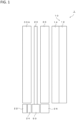
- FIG. 1 depicts a plan view showing schematically the arrangement as a whole of a false-twisting system 1.
- the false-twisting system 1 includes a machine 10 arranged to extend in a longitudinal direction.
- the machine 10 mainly includes, e.g., a false-twisting machine 12 and a winder 14.
- a yarn unwound from a yarn feeding package is fed from a creel stand 30 to the false-twisting machine 12.
- the creel stand 30 arranged adjacent to the machine 10 is configured as a mechanism to be supplied with a yarn feeding package by a creel robot 50, and to feed a yarn unwound from the supplied yarn feeding package to the false-twisting machine 12.
- the false-twisting system 1 corresponds to the "system" according to the present invention.
- the false-twisting machine 12 performs false-twisting on the yarn unwound from the yarn feeding package.
- the yarn subjected to the false-twisting is wound by the winder 14.
- the yarn feeding package supplied to the creel stand 30 is configured with a yarn-unwound cylindrical paper tube 100 (see FIG. 6 to be described later) having a yarn wound therearound.
- the paper tube 100 is also referred to as a bobbin, in general.
- the above-described paper tube 100 corresponds to the "yarn-unwound cylindrical member" according to the present invention.
- the yarn feeding package is supplied to the creel stand 30 by the creel robot 50 movable along a rail 20.
- the yarn feeding package is temporarily pooled in a raw yarn storage part 26 arranged adjacent to the creel stand 30 in a longitudinal direction, from a conveying equipment within an entire factory, and the creel robot 50 transfers the yarn feeding package pooled in the raw yarn storage part 26 to the creel stand 30.
- the yarn-unwound paper tube 100 (see FIG. 6 to be described later) without any yarn wound therearound is collected by the creel robot 50 movable along the rail 20.
- the yarn-unwound paper tube 100 collected by the creel robot 50 is collected into a yarn-unwound paper tube collection box 22 via a yarn-unwound paper tube collection chute 24 arranged adjacent to a creel stand 30A of another machine (not shown) arranged adjacent in a longitudinal direction.
- the above-described yarn-unwound paper tube collection box 22 described corresponds to the "collection container" according to the present invention.
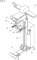
- FIG. 2 depicts a perspective view of the appearance of a creel robot 50.
- the creel robot 50 mainly includes a travel carriage 52 having a drive wheel 54 rotatable to travel along the rail 20 (see FIG. 1 ), a yarn replacing device 60 arranged so as to be adjustable in height with respect to the travel carriage 52, a rotation mechanism 65 configured to cause an orientation of the yarn replacing device 60 to rotate, a lifting up and down unit 66 configured to lift up and down the yarn replacing device 60, a peg shaft rotation mechanism 70 configured to cause a peg shaft 36 (see FIG. 4 to be described later) of the creel stand 30 (see FIG. 1 ) to rotate, and a yarn-unwound paper tube accommodation separation device 80 configured to separate a cap 110 to be described later (see FIG. 6 to be described later) from the yarn-unwound paper tube 100 (see FIG. 6 to be described later).
- the yarn replacing device 60 is configured to extract a yarn feeding package from the raw yarn storage part 26 (see FIG. 1 ), supply the yarn feeding package to the creel stand 30, and collect the yarn-unwound paper tube 100 from the creel stand 30.
- the yarn replacing device 60 includes a pair of yarn feeding package holding members 64 configured to hold a yarn feeding package.
- the pair of yarn feeding package holding members 64 is a pair of bar-like parallel members arranged so as to extend horizontally in a cantilevered manner.
- the yarn replacing device 60 is configured to hold a yarn feeding package by inserting the pair of yarn feeding package holding members 64 into the paper tube 100 (see FIG. 6 to be described later) of the yarn feeding package.
- the rotation mechanism 65 is configured to cause the yarn replacing device 60 to rotate horizontally so as to turn an orientation of the pair of yarn feeding package holding members 64. When the rotation mechanism 65 causes the yarn replacing device 60 to rotate, an orientation of the tips of the pair of yarn feeding package holding members 64 are turned. In an embodiment according to the present invention, the rotation mechanism 65 is configured to cause the yarn replacing device 60 to rotate within a range of 0 to 270 degrees in a clockwise direction, in the plan view. A rotation range of the yarn replacing device 60 is not limited to the above-described range.
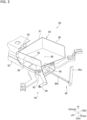
- FIG. 3 depicts a perspective view of a yarn-unwound paper tube accommodation separation device 80.
- an up-and-down direction, a left-and-right direction, and a forward-and-backward direction are defined as shown in FIG. 3 .
- the directions shown in FIG. 3 are defined solely for the purpose of convenience.
- the yarn-unwound paper tube accommodation separation device 80 includes a yarn-unwound paper tube accommodation box 84 configured to accommodate therein the yarn-unwound paper tube 100 obtained after yarn has been unwound thoroughly.
- the wall 85 is referred to as "first wall 85”
- the wall 86 is referred to as "second wall 86”
- the wall 87 is referred to as "third wall 87".
- the portion not surrounded by any wall out of four horizontal directions is opened.
- the opening is referred to as "opening 89".
- the above-described yarn-unwound paper tube accommodation box 84 corresponds to the "accommodation unit" according to the present invention.
- An orientation of tips of the pair of yarn feeding package holding members 64 is shifted generally by 90 degrees in the plan view, from an orientation of the opening 89 of the yarn-unwound paper tube accommodation box 84.
- the tip of the pair of yarn feeding package holding members 64 faces forward, e.g., the opening 89 of the yarn-unwound paper tube accommodation box 84 faces to the right.
- the tip of the pair of yarn feeding package holding members 64 faces to the left, e.g., the opening 89 of the yarn-unwound paper tube accommodation box 84 faces forward.
- the yarn-unwound paper tube accommodation box 84 has an upper portion opened, and a lower bottom plate 88.
- the bottom plate 88 is inclined to be lowered from the first wall 85 to the second wall 86.
- the yarn-unwound paper tube accommodation separation device 80 includes a base member 82, an extraction unit 90 arranged so as to be movable horizontally in a forward-and-backward direction with respect to the base member 82, and an extraction unit movement mechanism (not shown) configured to cause the extraction unit 90 to move.
- the extraction unit 90 includes a bar-like member 90a lengthwise in an up-and-down direction, and a shaft member 90b lengthwise in a forward-and-backward direction attached with the bar-like member 90a at a tip thereof.
- the extraction unit movement mechanism as a well-known configuration not described in detail herein, is configured to cause the bar-like member 90a to move in a forward-and-backward direction via the shaft member 90b.
- the extraction unit movement mechanism causes the bar-like member 90a to move in a forward-and-backward direction as described above so that the bar-like member 90a moves between a position close to the opening 89 and a position far away from the opening 89.
- the creel robot 50 further includes an accommodation box rotation mechanism 94.
- the accommodation box rotation mechanism 94 is configured with an operation part 96, and, e.g., a shaft support part 95 supported pivotally with respect to the base member 82.
- the shaft support part 95 has a shaft along a left-and-right direction.
- the accommodation box rotation mechanism 94 is configured to cause the yarn-unwound paper tube accommodation box 84 to rotate around the shaft support part 95 with respect to the base member 82.
- the yarn-unwound paper tube accommodation box 84 having the yarn-unwound paper tube 100 accommodated therein is caused to rotate so as to be lowered backward, the yarn-unwound paper tube 100 can be caused to move backward.
- the yarn-unwound paper tube accommodation box 84 is caused to rotate so as to be lowered forward, the yarn-unwound paper tube 100 can be caused to move forward.
- the yarn-unwound paper tube accommodation separation device 80 includes an electromagnet 92 and a vibration generation part 93.
- the electromagnet 92 and the vibration generation part 93 are shown only in FIG. 3 , and are not shown in other figures.
- the electromagnet 92 is arranged on, e.g., a rear surface of the third wall 87.
- the third wall 87 is made of ferromagnetic material such as iron or cobalt.
- the electromagnet 92 becomes magnetic when being energized by causing an electric current to flow therethrough, and becomes non-magnetic when not being energized by stopping the flow of electric current.
- the vibration generation part 93 is arranged on, e.g., a lower surface of the bottom plate 88.
- the vibration generation part 93 is configured to vibrate the yarn-unwound paper tube accommodation box 84 via, e.g., the bottom plate 88.
- At least one of the electromagnet 92 and the vibration generation part 93 corresponds to the "separator device" according to the present invention.
- FIG. 4 depicts a perspective view showing schematically the operation of the creel robot 50 to replace a yarn feeding package with respect to a creel stand 30.
- the yarn feeding package is not shown in FIG. 4 .
- an up-and-down direction, a left-and-right direction, and a forward-and-backward direction are defined according to FIG. 4 .
- Such directions shown in FIG. 4 are not related to directions shown in FIG. 3 .
- the creel stand 30 has a pole 32 lengthwise in an up-and-down direction and is inserted in a rotation cylinder 34.
- the rotation cylinder 34 is configured to be rotatable with respect to the pole 32 around an axis corresponding to a longitudinal direction ( i.e ., an up-and-down direction) of the pole 32.
- the peg shaft 36 and a claw 38 are arranged on the rotation cylinder 34.
- the peg shaft rotation mechanism 70 has an engagement part 72, and the claw 38 is configured to be engaged with the engagement part 72.
- the peg shaft rotation mechanism 70 operates, the claw 38 is caused to rotate via the engagement part 72 with respect to the pole 32.
- the peg shaft 36 is caused to rotate with respect to the pole 32 accordingly.
- the creel robot 50 replaces a yarn feeding package to the creel stand 30, e.g., in the following manner. It is noted that, when the creel robot 50 replaces a yarn feeding package to the creel stand 30, a tip of the pair of yarn feeding package holding members 64 faces forward ( i.e ., to the creel stand 30), and the opening 89 of the yarn-unwound paper tube accommodation box 84 faces to the right. A tip of the peg shaft 36 faces backward ( i.e ., to the creel robot 50).
- the creel robot 50 having transferred a yarn feeding package in proximity to the creel stand 30 adjusts the yarn replacing device 60 (see FIG. 2 ) in height through the use of the lifting up and down unit 66 (see FIG. 2 ) so that the pair of yarn feeding package holding members 64 substantially coincide in height with the peg shaft 36.
- the creel robot 50 causes the pair of yarn feeding package holding members 64 to advance to the peg shaft 36 ( i.e ., causes the pair of yarn feeding package holding members 64 to move forward).
- the creel robot 50 then lowers the yarn replacing device 60 to transfer the yarn feeding package held by the yarn feeding package holding members 64 onto the peg shaft 36, and thereafter causes the pair of yarn feeding package holding members 64 to retreat backward.
- the creel robot 50 drives the peg shaft rotation mechanism 70 to cause the rotation cylinder 34 to rotate so that a tip of the peg shaft 36 faces forward.
- FIG. 5 depicts a perspective view showing schematically the operation of the creel robot to collect a yarn-unwound paper tube.
- an up-and-down direction, a left-and-right direction, and a forward-and-backward direction are defined according to FIG. 4 .
- the creel robot 50 collects the yarn-unwound paper tube 100, e.g., in the following manner. It is noted that, when the creel robot 50 collects the yarn-unwound paper tube 100, the opening 89 of the yarn-unwound paper tube accommodation box 84 faces forward ( i.e. , to the creel stand 30), and a tip of the pair of yarn feeding package holding members 64 faces to the left.
- a distance in a forward-and-backward direction between the opening 89 of the yarn-unwound paper tube accommodation box 84 and a tip of the peg shaft 36 is preferably minimized as much as possible, and is preferably at least shorter than a length in a forward-and-backward direction of the yarn-unwound paper tube 100. This ensures the accommodation of the yarn-unwound paper tube 100 in the yarn-unwound paper tube accommodation box 84 without falling off.
- the creel robot 50 adjusts the bar-like member 90a in height through the use of the lifting up and down unit 66 so that an upper end of the bar-like member 90a is lower than a lower end of the yarn-unwound paper tube 100 installed on the peg shaft 36.
- the creel robot 50 thereafter causes the shaft member 90b to move forward ( i.e. , to the peg shaft 36) so that the bar-like member 90a is positioned in front of the yarn-unwound paper tube 100 installed on the peg shaft 36.
- the creel robot 50 thereafter adjusts the bar-like member 90a in height through the use of the lifting up and down unit 66 so that the bar-like member 90a is brought into contact with the yarn-unwound paper tube 100.
- the creel robot 50 causes the bar-like member 90a to move backward ( i.e. , to approach the opening 89) while keeping the bar-like member 90a in contact with the yarn-unwound paper tube 100.
- the creel robot 50 causes the yarn-unwound paper tube 100 installed on the peg shaft 36 to move to the opening 89 thereby to accommodate the yarn-unwound paper tube 100 in the yarn-unwound paper tube accommodation box 84.
- FIG. 6 depicts a perspective view of a yarn-unwound paper tube obtained after a yarn has been unwound thoroughly.
- the paper tube 100 is a yarn-unwound cylindrical member.
- the cap 110 made of, e.g., a plastic magnet in a circular outer shape is fitted to an end part 102 as one end in a longitudinal direction of the paper tube 100.
- the cap 110 fitted to an end part of the paper tube 100 serves as a guide used when yarn is unwound from a yarn feeding package.
- the cap 110 is fitted to the paper tube 100 when an operator joins the yarn tails of yarn feeding packages.
- the cap 110 has a flange 111 having a hollow portion 112, and a supported member 114 to be supported by an inner peripheral surface 104 of the paper tube 100.
- the supported member 114 is arranged in the hollow portion 112 of the flange 111.
- the outer diameter of the flange 111 (i.e., the outer diameter of the cap 110) is larger than the outer diameter of the paper tube 100.
- the above-described flange 111 corresponds to the "flange part" according to the present invention.
- the above-described supported member 114 corresponds to the "fitting part" according to the present invention.
- the supported member 114 has, e.g., four supported parts 115 (see (A) of FIG. 8 and (B) of FIG. 8 to be described later, for more details) to be supported by the inner peripheral surface 104 of the paper tube 100.
- An end surface of the paper tube 100 is brought into contact with a surface of the cap 110 so that the supported parts 115 are inserted inside the inner peripheral surface 104 of the paper tube 100, and thereby the cap 110 is fitted to the paper tube 100.
- FIG. 7 and FIG. 8 show an example of the step of separating the cap 110 from the paper tube 100.
- (A) of FIG. 7 is a perspective view showing the operation to collect the yarn-unwound paper tube 100 obtained after a yarn has been unwound thoroughly from the peg shaft 36 into the yarn-unwound paper tube accommodation box 84.
- (B) of FIG. 7 is a perspective view showing the state before the cap 110 is separated from the yarn-unwound paper tube 100.
- (A) of FIG. 8 is a perspective view illustrating a state after the cap 110 is separated from the yarn-unwound paper tube 100.
- FIG. 8 is a perspective view showing the operation to collect a yarn-unwound cylindrical paper tube 100 having been separated from the cap 110.
- an up-and-down direction, a left-and-right direction, and a forward-and-backward direction are defined according to FIG. 7 and FIG. 8 .
- the cap 110 is made of, e.g., a plastic magnet.
- the third wall 87 is configured to become magnetic when an electric current is caused to flow through the electromagnet 92.
- a rear surface of the cap 110 is in contact with the third wall 87 in its magnetic state, a rear surface of the cap 110 is attracted to the third wall 87, as shown in FIG. 7B .
- the above-described third wall 87 corresponds to the "attraction part" according to the present invention.
- the cap 110 When a rear surface of the cap 110 is attracted to the third wall 87, the cap 110 having an outer diameter larger than an outer diameter of the paper tube 100 is in a state of floating above the bottom plate 88. Accordingly, the yarn-unwound paper tube 100 is likely to drop off from the cap 110 due to the force of gravity.
- the yarn-unwound paper tube accommodation box 84 is caused to rotate so as to be lowered backward, through the operation with the operation part 96.
- This causes the yarn-unwound paper tube 100 to move backward, and brings a rear surface of the cap 110 into contact with the third wall 87.
- the operation with the operation part 96 to cause the yarn-unwound paper tube accommodation box 84 to rotate so as to be lowered backward may be performed by a controller equipped with CPU, or may be performed manually by an operator.
- the yarn-unwound paper tube accommodation box 84 may be kept to be lowered backward without any rotation to be lowered backward, unless the yarn-unwound paper tube accommodation box 84 is caused to rotate otherwise so as to be lowered forward.
- a manner to bring a rear surface of the cap 110 into contact with the third wall 87 is not limited to lowering the yarn-unwound paper tube accommodation box 84 backward.
- a manner may be of pushing and moving the yarn-unwound paper tube 100 rearward through the use of, e.g., a member lengthwise in a forward-and-backward direction attached to the bar-like member 90a.
- the cap 110 is configured with a plastic magnet
- a part of the cap 110 as a whole may not be configured with a plastic magnet as long as the cap 110 is attracted to the third wall 87 serving as a magnetic body.
- the rear surface of the cap 110 may be partially made of a plastic magnet, and the whole rear surface of the cap 110 may not be a plastic magnet.
- the cap 110 may have a rear surface of non-plastic magnet, and may have a front surface made of a plastic magnet as long as the cap 110 has a strong enough magnetic force to come into contact with the third wall 87.
- the portion configured with a plastic magnet in the cap 110 corresponds to the "magnetic part" according to the present invention.
- the yarn-unwound paper tube accommodation separation device 80 includes the vibration generation part 93.
- the vibration generation part 93 vibrates the yarn-unwound paper tube accommodation box 84 in a state where a rear surface of the cap 110 is attracted to the third wall 87.
- the yarn-unwound paper tube 100 is subjected to the force of gravity.
- the vibration by the vibration generation part 93 to the yarn-unwound paper tube accommodation box 84 in addition to the force of gravity, facilitates the separation between the cap 110 and the yarn-unwound paper tube 100.
- the bottom plate 88 is inclined to be lowered to the right. Therefore, the yarn-unwound paper tube 100 separated from the cap 110 rotates so as to move to the right ( i.e. , to a direction away from the cap 110) due to the force of gravity. This ensures the separation between the cap 110 and the paper tube 100 by preventing the cap 110 having been separated from the yarn-unwound paper tube 100 from being re-fitted to the yarn-unwound paper tube 100 unintentionally.
- the vibration generation part 93 stops vibrating the yarn-unwound paper tube accommodation box 84 after, e.g., a predetermined period of time has elapsed since the start of vibrating the yarn-unwound paper tube accommodation box 84.
- the predetermined period of time described above is set as, e.g., the time required to separate the cap 110 from the yarn-unwound paper tube 100.
- the paper tube 100 is not magnetic, and is thus not attracted to the third wall 87.
- the yarn-unwound paper tube accommodation box 84 may be oscillated, instead of or in addition to being vibrated.
- the yarn-unwound paper tube accommodation box 84 rotates around the shaft support part 95 so as to be lowered forward through the operation with the operation part 96 as shown in FIG. 8 .
- the yarn-unwound paper tube 100 having been discharged forward through the opening 89 is collected via the yarn-unwound paper tube collection chute 24 (see FIG. 1 ) into the yarn-unwound paper tube collection box 22 (see FIG. 1 ).
- the operation with the operation 96 to rotate the yarn-unwound paper tube accommodation box 84 so as to be lowered forward may be performed by a controller equipped with CPU, or may be performed manually by an operator.
- the vibration generation part 93 stops vibrating the yarn-unwound paper tube accommodation box 84 (more specifically, e.g., the bottom plate 88) after the yarn-unwound paper tube 100 is separated from the cap 110.
- the timing to stop the vibration is not limited thereto.
- the vibration generation part 93 may stop vibrating the yarn-unwound paper tube accommodation box 84 after the yarn-unwound paper tube 100 is discharged forward through the opening 89 of the yarn-unwound paper tube accommodation box 84.
- the operation part 96 is operated to return the yarn-unwound paper tube accommodation box 84 to the initial position. Thereafter, the electric current flowing through the electromagnet 92 is stopped so that the third wall 87 becomes nonmagnetic, and the cap 110 is collected.
- the cap 110 may be collected by an operator. More preferably, the creel robot 50 may move to the cap collection box (not shown) provided separately from the yarn-unwound paper tube collection box 22, and may collect the cap 110 in the cap collection box.
- the cap collection box since the cap collection box is arranged at a position different from the yarn-unwound paper tube collection box 22, the cap collection box may be arranged flexibly without any restriction in position.
- the operation with the operation part 96 to return the yarn-unwound paper tube accommodation box 84 to the initial position may be performed by a controller equipped with CPU, or may be manually performed by an operator.
- the creel robot 50 in an embodiment according to the present invention extracts the yarn-unwound paper tube 100 obtained after yarn has been thoroughly unwound from the yarn feeding package from the peg shaft 36 of the creel stand 30 thereby to accommodate the yarn-unwound paper tube 100 in the yarn-unwound paper tube accommodation box 84.
- the yarn-unwound paper tube 100 accommodated in the yarn-unwound paper tube accommodation box 84 is fitted with the cap 110.
- the yarn-unwound paper tube accommodation box 84 is made to vibrate or oscillate in the state where the cap 110 is attracted to the third wall 87 of the yarn-unwound paper tube accommodation box 84, and thereby the cap 110 is separated from the yarn-unwound paper tube 100.
- the yarn-unwound paper tube 100 separated from the cap 110 is collected in the yarn-unwound paper tube collection box 22, and the cap 110 is collected separately from the yarn-unwound paper tube 100. This allows the yarn-unwound paper tube 100 to be collected while preventing the cap 110 from being damaged, with eliminating the needs for an operator to face a burden of going to the creel stand 30 to collect the cap 110, thereby capable of achieving man-power savings.
- the paper tube 100 is nonmagnetic, while the cap 110 has plastic magnetic properties. Therefore, such a simple configuration in which the yarn-unwound paper tube accommodation box 84 is made to vibrate and oscillate in a state where the cap 110 is attracted to the third wall 87 allows the yarn-unwound paper tube 100 to be separated from the cap 110.
- the bottom plate 88 of the yarn-unwound paper tube accommodation box 84 is preferably inclined with respect to the horizontal direction.
- the inclined bottom plate 88 of the yarn-unwound paper tube accommodation box 84 allows the yarn-unwound paper tube 100 to rotate and move due to the force of gravity, thereby capable of surely separating the cap 110 from the yarn-unwound paper tube 100.
- the third wall 87 generates a magnetic force when an electric current flows through the electromagnet 92 arranged behind the third wall 87.
- an electric current is caused to flow therethrough, while when collecting the cap 110, an electric current is not caused to flow therethrough. This facilitates the collection of the cap 110.
- the third wall 87 becomes magnetic when an electric current flows through the electromagnet 92.
- at least one of the first wall 85, the second wall 86, and the bottom plate 88 may become magnetic.
- all of the first wall 85, the second wall 86, the third wall 87, and the bottom plate 88 may become magnetic, as with the third wall 87.
- the electromagnet 92 is arranged on, for example, the rear surface of the third wall 87, and the third wall 87 becomes magnetic when an electric current flows through the electromagnet 92.
- a permanent magnet may be used instead of the electromagnet 92.
- the configuration eliminates the needs of control such as the electrification of the electromagnet 92, thus easily allowing the cap 110 to be attracted to the third wall 87.
- the vibration generation part 93 vibrates the yarn-unwound paper tube accommodation box 84 in the state where the front surface of the cap 110 is attracted to the third wall 87, thereby separating the yarn-unwound paper tube 100 from the cap 110.
- the configuration is not limited thereto.
- the yarn-unwound paper tube accommodation box 84 may be oscillated, instead of or in addition to being vibrated.
- the oscillation generation part configured to oscillate the yarn-unwound paper tube accommodation box 84 in a left-and-right direction may be included.
- the oscillation generation part oscillates the yarn-unwound paper tube accommodation box 84 in the state where the rear surface of the cap 110 is attracted to the third wall 87, thus separating the yarn-unwound paper tube 100 from the cap 110.
- force may be applied to the paper tube 100 in a direction along the surface of the cap 110 in the state where the rear surface of the cap 110 is attracted to the third wall 87, thereby separating the yarn-unwound paper tube 100 from the cap 110.
- the creel robot 50 includes the yarn-unwound paper tube accommodation separation device 80.
- the creel robot 50 may not necessarily include the yarn-unwound paper tube accommodation separation device 80.
- the yarn-unwound paper tube accommodation separation device 80 may be provided separately from the creel robot 50.
- the creel robot 50 may collect the yarn-unwound paper tube 100 (the yarn-unwound paper tube 100 fitted with the cap 110) obtained after yarn has been unwound thoroughly, from the peg shaft 36, and thereafter may supply the yarn-unwound paper tube 100 to the yarn-unwound paper tube accommodation separation device 80 provided separately from the creel robot 50.
- the present invention may relate to the false twist texturing system 1 including at least: the machine 10 including at least the false twist texturing machine 12 configured to process the yarn unwound from a yarn feeding package, and the winder 14 configured to wind the yarn processed by the false twist texturing machine 12; the creel stand 30 which is arranged adjacent to the machine 10 and configured to feed the yarn unwound from a yarn feeding package to the machine 10 (the false twist texturing machine 12); and the creel robot 50 configured to supply the yarn feeding package to the creel stand 30.
- the yarn feeding package has the paper tube 100 fitted with the cap 110 at the end part 102 thereof, and that the creel robot 50 has the yarn-unwound paper tube accommodation box 84 configured to accommodate the yarn-unwound paper tube 100 which is subjected to thorough yarn unwinding from the yarn feeding package having the paper tube 100 fitted with the cap 110 at the end part 102 and thereafter extracted from the peg shaft 36 of the creel stand 30.
- the false twist texturing system 1 preferably further includes the yarn-unwound paper tube accommodation separation device 80 configured to separate the yarn-unwound paper tube 100 accommodated in the yarn-unwound paper tube accommodation box 84 from the cap 110 fitted to the yarn-unwound paper tube 100, and the yarn-unwound paper tube collection box 22 for collecting therein the yarn-unwound paper tube 100 separated from the cap 110 by the yarn-unwound paper tube accommodation separation device 80.
- the yarn-unwound paper tube accommodation separation device 80 configured to separate the yarn-unwound paper tube 100 accommodated in the yarn-unwound paper tube accommodation box 84 from the cap 110 fitted to the yarn-unwound paper tube 100
- the yarn-unwound paper tube collection box 22 for collecting therein the yarn-unwound paper tube 100 separated from the cap 110 by the yarn-unwound paper tube accommodation separation device 80.
- the yarn-unwound paper tube 100 fitted with the cap 110 is extracted from the peg shaft 36 of the creel stand 30 and separated from the cap 110, and thereafter the yarn-unwound paper tube 100 is collected in the yarn-unwound paper tube collection box 22.
- This allows the yarn-unwound paper tube 100 to be collected while preventing the cap 110 from being damaged with eliminating the needs for an operator to face a burden of going to the creel stand to collect the cap 110, thus achieving man-power savings.
- a separator device 80A to be described later instead of the yarn-unwound paper tube accommodation separation device 80, may be configured to separate the yarn-unwound paper tube 100 from the cap 110.
- the separator device 80A will be described below with reference to FIG. 9 .
- an up-and-down direction, a left-and-right direction, and a forward-and-backward direction in the description below are defined according to FIG. 9 .
- FIG. 9 depicts a perspective view (A) showing schematically a yarn-unwound paper tube collection chute 24A viewed from a right-side above, and depicts a perspective view (B) showing schematically a yarn-unwound paper tube collection chute 24A viewed from a left-side above.
- the yarn-unwound paper tube collection chute 24A includes the separator device 80A configured to separate the yarn-unwound paper tube 100 from the cap 110.
- the yarn-unwound paper tube collection chute 24A is arranged at, for example, the same position as the yarn-unwound paper tube collection chute 24 shown in FIG. 1 .
- the yarn-unwound paper tube collection chute 24A may be arranged at any position in a false twist texturing system, preferably at a position adjacent to a yarn-unwound paper tube collection box.
- the yarn-unwound paper tube collection chute 24A includes a paper tube entry port 241A.
- the yarn-unwound paper tube 100 discharged from a creel robot not shown is entered into the yarn-unwound paper tube collection chute 24A through the paper tube entry port 241A.
- the creel robot other than the configurations above is the same as the creel robot 50 shown in FIG. 2 .
- the creel robot not shown but described above includes the yarn-unwound paper tube accommodation box 84 (see FIG. 3 ), and is configured to accommodate the yarn-unwound paper tube 100 which is subjected to thorough yarn unwinding from the yarn feeding package having the paper tube 100 fitted with the cap 110 and is extracted from the peg shaft 36 of the creel stand 30 (see FIG. 4 for both).
- the creel robot no shown but described above further includes the accommodation box rotation mechanism 94 (see FIG. 3 ), and discharges forward the yarn-unwound paper tube100 which is extracted from the peg shaft 36 of the creel stand 30 and is accommodated in the yarn-unwound paper tube accommodation box 84.
- the yarn-unwound paper tube 100 accommodated in the yarn-unwound paper tube accommodation box 84 is discharged in the state of being fitted with the cap 110.
- the yarn-unwound paper tube 100 discharged as described above is entered into the yarn-unwound paper tube collection chute 24A through the paper tube entry port 241A described above.
- the separator device 80A is arranged on the passing path for the yarn-unwound paper tube 100 entered into the yarn-unwound paper tube collection chute 24A through the paper tube entry port 241A.
- the separator device 80A is, for example, a plate member, and has an opening 81A.
- the separator device 80A of a plate member is arranged to be lowered to the left.
- a paper tube collection path 242A and a cap collection path 243A are formed on the downstream side of the force of gravity with respect to the separator device 80A.
- the paper tube collection path 242A and the cap collection path 243A are partitioned.
- a yarn-unwound paper tube collection box (not shown) is arranged on the downstream side of the force of gravity with respect to the paper tube collection path 242A.
- a cap collection box (not shown) is arranged.
- the opening 81A is opened in a circular shape larger than the outer diameter of the yarn-unwound paper tube 100 so as to allow the yarn-unwound paper tube 100 entered into the yarn-unwound paper tube collection chute 24A through the paper tube entry port 241A and falling off due to the force of gravity to pass through.
- the opening 81A is opened in the shape smaller than the outer diameter of the flange 111 (see FIG. 6 ) included in the cap 110.
- the cap 110 fitted to the yarn-unwound paper tube 100 does not pass through the opening 81A, while the yarn-unwound paper tube 100 passes through the opening 81A.
- the separator device 80A separates the yarn-unwound paper tube 100 from the cap 110
- the yarn-unwound paper tube 100 separated from the cap 110 passes through the paper tube collection path 242A, and is collected in the yarn-unwound paper tube collection box (not shown).
- the cap 110 separated from the yarn-unwound paper tube 100 moves to the left along the separator device 80A arranged so as to be lowered, for example, to the left, and passes through the cap collection path 243A.
- the cap 110 having passed through the cap collection path 243A is collected in the cap collection box (not shown).
- the cap collection box may be arranged to be higher than the yarn-unwound paper tube collection box so as to prevent the collected cap 110 from being damaged, or may be arranged with a buffer member.
- the separator device 80A is configured to separate the cap 110 fitted to the yarn-unwound paper tube 100, from the yarn-unwound paper tube 100 having discharged from the yarn-unwound paper tube accommodation box 84 (see FIG. 3 ) of the creel robot (not shown). After the yarn-unwound paper tube 100 is separated from the cap 110, the yarn-unwound paper tube 100 passes downstream through the paper tube collection path 242A, and the cap 110 passes downstream through the cap collection path 243A. The yarn-unwound paper tube 100 and the cap 110 having been separated from each other are thus collected in different collection boxes.
- the yarn-unwound paper tube collection chute 24A includes the above-described separator device 80A, the configuration is not limited thereto.
- the creel robot (not shown) may include the above-described separator device 80A.
- the creel robot does not include the electromagnet 92 or the vibration generation part 93 (see FIG. 3 for both).
- the configuration is not limited thereto.
- the false twist texturing system may include both of the creel robot 50 including the yarn-unwound paper tube accommodation separation device 80 (see FIG. 3 ) described in the present embodiment, and the yarn-unwound paper tube collection chute 24A including the separator device 80A described in the modification. In this case, even when the yarn-unwound paper tube accommodation separation device 80 fails to separate the yarn-unwound paper tube 100 from the cap 110, the separator device 80A is able to separate the yarn-unwound paper tube 100 from the cap 110.
Landscapes
- Replacing, Conveying, And Pick-Finding For Filamentary Materials (AREA)
- Unwinding Of Filamentary Materials (AREA)
Abstract
Description
- The present invention relates to a creel robot for extracting a yarn-unwound paper tube from a creel stand and a system including the same.
- Conventionally, a false-twisting machine has been provided with a creel stand arranged adjacent to a machine, and a yarn feeding package has been supplied to a peg shaft of the creel stand by a creel robot. The yarn feeding package has been obtained as a result of winding a yarn around a cylindrical paper. The yarn having been unwound from the yarn feeding package supplied to the peg shaft of the creel stand has been fed to the machine so as to be subjected to, e.g., drawing false-twisting.
- The creel robot disclosed in, e.g.,
Patent Document 1 has extracted the yarn-unwound paper tube obtained after the yarn has been thoroughly unwound from a yarn feeding package from the peg shaft of the creel stand, and installed another new yarn feeding package thereto. The robot has removed the extracted yarn-unwound paper tube away from the peg shaft of the creel stand, and has dropped the removed yarn-unwound paper tube on a paper-tube-receiving base thereby to collect the yarn-unwound paper tube. - Patent Document 1:
Japanese Patent Application Publication No. H06-56352 - In recent years, some paper tube has been fitted with, at an end thereof, a cap larger in outer diameter than the paper tube configured to serve as a guide for unwinding the yarn from the yarn feeding package.
- The above-described cap has been reused through a step of detaching the cap from the yarn-unwound paper tube and attaching the detached cap to another new yarn feeding package. Since a robot (hereinafter, referred to as a "creel robot") has dropped the extracted yarn-unwound paper tube on the paper-tube-receiving base thereby to collect the yarn-unwound paper tube, there has been a probability that the cap fitted to the yarn-unwound paper tube would be damaged. For this reason, an operator had to collect the cap before the creel robot's collecting the yarn-unwound paper tube. In such a situation, the operator had to face a large burden of going to the creel stand, and there has been a room for improvement from the viewpoint of man-power savings.
- The present invention has been made in view of the above-described technical problems, and an objective thereof is to provide a creel robot capable of achieving man-power savings while preventing a cap from being damaged, and a system including the same.
- A first aspect of the present invention is a creel robot for extracting a yarn-unwound cylindrical member obtained after a yarn has been thoroughly unwound from a yarn feeding package from a peg shaft of a creel stand thereby to collect the yarn-unwound cylindrical member, wherein the yarn feeding package has the yarn-unwound cylindrical member fitted with a cap at an end thereof, the creel robot comprising:
- an accommodation unit configured to accommodate therein the yarn-unwound cylindrical member;
- an extraction unit configured to extract the yarn-unwound cylindrical member in a state where the cap is fitted thereto from the peg shaft of the creel stand to cause the accommodation unit to accommodate therein the yarn-unwound cylindrical member; and
- a separator device configured to separate the cap fitted to the yarn-unwound cylindrical member accommodated in the accommodation unit from the yarn-unwound cylindrical member,
- wherein the yarn-unwound cylindrical member having been separated from the cap is collected in a predetermined collection container.
- According to the creel robot in the above-described first aspect of the present invention, the yarn-unwound cylindrical member in a state where the cap is fitted thereto having been extracted from the peg shaft of the creel stand is separated from the cap, and thereafter collected in the predetermined collection container. This allows the yarn-unwound cylindrical member to be collected while preventing the cap from being damaged, with eliminating the needs for an operator to face a burden of going to the creel stand to collect the cap, thus capable of achieving man-power savings.
- The above-described yarn-unwound cylindrical member is, e.g., a bobbin allowing a yarn thread to be wound therearound.
- A second aspect of the present invention is the creel robot, preferred wherein the yarn-unwound cylindrical member is not magnetic while the cap includes at least a magnetic part having magnetic properties, the accommodation unit has an attraction part capable of being attracted with the magnetic part, and the separator device is configured to separate the cap having the magnetic part from the yarn-unwound cylindrical member in a state where the magnetic part is attracted to the attraction part.
- According to the creel robot in the above-described second aspect of the present invention, the cap including at least the magnetic part having magnetic properties in a state where the magnetic part is attracted to the attraction part can be separated from the yarn-unwound cylindrical member. As a result, the creel robot in a simple configuration without any mechanism to hold the cap in separating the cap from the yarn-unwound cylindrical member is capable of separating the cap from the yarn-unwound cylindrical member.
- It is to be noted that the cap having the magnetic part may be separated from the yarn-unwound cylindrical member by, e.g., applying force to the yarn-unwound cylindrical member in a state where the magnetic part included in the cap is attracted to the attraction part. A manner of applying force to the yarn-unwound cylindrical member is not particularly limited as long as such a force can physically separate the cap from the yarn-unwound cylindrical member.
- A third aspect of the present invention is the creel robot, preferred wherein the separator device is configured to vibrate or oscillate the accommodation unit at least in a state where the magnetic part is attracted to the attraction part.
- According to the creel robot in the above-described third aspect of the present invention, the vibration or oscillation of the accommodation unit in a state where the magnetic part is attracted to the attraction part allows the cap and the yarn-unwound cylindrical member to be separated from each other. As a result, the creel robot in a simple configuration without any mechanism to physically separate the cap from the yarn-unwound cylindrical member is capable of separating the cap from the yarn-unwound cylindrical member.
- It is to be noted that the accommodation unit is preferably inclined with respect to a horizontal direction. The inclined accommodation unit, when the cap is separated from the yarn-unwound cylindrical member due to the vibration or oscillation of the accommodation unit, allows the yarn-unwound cylindrical member to rotate to move due to the force of gravity, thereby to ensure the separation between the cap and the yarn-unwound cylindrical member.
- A fourth aspect of the present invention is the creel robot, preferred wherein the attraction part generates a magnetic force when being energized.
- According to the creel robot in the above-described fourth aspect of the present invention, an electric current is caused to flow when separating the cap from the yarn-unwound cylindrical member, while an electric current is not caused to flow when collecting the cap. This facilitates the collection of the cap.
- A fifth aspect of the present invention is the creel robot, preferred wherein the cap has a fitting part configured to be detachably fitted to an inner periphery of the yarn-unwound cylindrical member, and a flange part larger in outer diameter than the cylindrical member, wherein the separator device having an opening larger in outer diameter than the yarn-unwound cylindrical member as well as smaller in outer diameter than the cap is configured to prevent the cap from passing through the opening while allow the yarn-unwound cylindrical member to pass through the opening, thereby to separate the cap from the yarn-unwound cylindrical member.
- According to the creel robot in the above-described fifth aspect, a simple configuration merely to allow the yarn-unwound cylindrical member to pass through the opening larger in outer diameter than the yarn-unwound cylindrical member and smaller in outer diameter than the cap is capable of separating the cap from the yarn-unwound cylindrical member.
- A sixth aspect of the present invention is a system comprising:
- a machine including a winder configured to wind a yarn having been unwound from a yarn feeding package;
- a creel stand arranged adjacent to the machine configured to feed the yarn having been unwound from the yarn feeding package to the machine; and
- a creel robot configured to supply the yarn feeding package to the creel stand, wherein
- the yarn feeding package has a yarn-unwound cylindrical member fitted with a cap at an end thereof, and wherein
- the creel robot includes an accommodation unit configured to accommodate therein a yarn-unwound cylindrical member obtained after a yarn has been thoroughly unwound from the yarn feeding package to be extracted from a peg shaft of the creel sta nd,
- the system further comprising:
- a separator device configured to separate the cap fitted to the yarn-unwound cylindrical member accommodated in the accommodation unit from the yarn-unwound cylindrical member; and
- a collection container for collecting therein the yarn-unwound cylindrical member having been separated from the cap by the separator device.
- According to the system in the above-described sixth aspect, the yarn-unwound cylindrical member fitted with the cap is extracted from the peg shaft of the creel stand to be separated from the cap, and thereafter collected in the predetermined collection container. This allows the yarn-unwound cylindrical member to be collected while preventing the cap from being damaged, with eliminating the needs for an operator to take the trouble to go to the creel stand to collect the cap, thus capable of achieving man-power savings.
- The creel robot according to the present invention may not necessarily include all configurations in the above-described first to fifth aspects. The creel robot in the above-described first aspect, e.g., may not necessarily include the configurations in the above-described second to fifth aspects. Further, the creel robot according to the present invention may be obtained as a result of combining arbitrarily to such an extent that consistency can be achieved: a configuration in the above-described first aspect; and a part or the entirety of configurations in the above-described second to fifth aspects. Still further, the creel robot according to the present invention may be obtained as a result of combining: a configuration in the above-described first aspect; and a part or the entirety of configurations in the above-described second to fifth aspects. Still further, the system in the above-described sixth aspect of the present invention may include a part or the entirety of configurations of the creel robot in the above-described first to fifth aspects to such an extent that consistency can be achieved.
- According to the present invention, there can be provided: a creel robot capable of achieving man-power savings while preventing a cap from being damaged; and a system including the same.
-
-
FIG. 1 depicts a plan view showing schematically the arrangement as a whole of a false-twisting system. -
FIG. 2 depicts a perspective view of the appearance of a creel robot. -
FIG. 3 depicts a perspective view of a yarn-unwound paper tube accommodation separation device. -
FIG. 4 depicts a perspective view showing schematically the operation of the creel robot to replace a yarn feeding package with respect to a creel stand. -
FIG. 5 depicts a perspective view showing schematically the operation of the creel robot to collect a yarn-unwound paper tube. -
FIG. 6 depicts a perspective view of a yarn-unwound paper tube obtained after a yarn has been unwound thoroughly. -
FIG. 7 depicts a perspective view (A) showing the operation to collect a yarn-unwound paper tube obtained after a yarn has been unwound thoroughly from a peg shaft into a yarn-unwound paper tube accommodation box, and depicts another perspective view (B) showing a state before a cap is separated from a yarn-unwound paper tube. -
FIG. 8 depicts a perspective view (A) showing a state after a cap is separated from a yarn-unwound paper tube, and depicts a perspective view (B) showing the operation to collect a yarn-unwound cylindrical paper tube having been separated from a cap. -
FIG. 9 depicts a perspective view (A) showing schematically a yarn-unwound paper tube collection chute viewed from a right-side above, and depicts a perspective view (B) showing schematically a yarn-unwound paper tube collection chute viewed from a left-side above. - Hereinafter, embodiments according to the present invention will be described with reference to the drawings.
-
FIG. 1 depicts a plan view showing schematically the arrangement as a whole of a false-twistingsystem 1. As shown inFIG. 1 , the false-twistingsystem 1 includes amachine 10 arranged to extend in a longitudinal direction. Themachine 10 mainly includes, e.g., a false-twistingmachine 12 and awinder 14. On the both sides of the false-twistingmachine 12, there are a yarn feeding roller (not shown), a heater (not shown), a twisting device (not shown), and a number of yarn processing spindles configured with yarn processing mechanism (not shown) for the above-describedwinder 14 and the like. A yarn unwound from a yarn feeding package is fed from acreel stand 30 to the false-twistingmachine 12. The creel stand 30 arranged adjacent to themachine 10 is configured as a mechanism to be supplied with a yarn feeding package by acreel robot 50, and to feed a yarn unwound from the supplied yarn feeding package to the false-twistingmachine 12. The false-twistingsystem 1 corresponds to the "system" according to the present invention. - The false-twisting
machine 12 performs false-twisting on the yarn unwound from the yarn feeding package. The yarn subjected to the false-twisting is wound by thewinder 14. - The yarn feeding package supplied to the
creel stand 30 is configured with a yarn-unwound cylindrical paper tube 100 (seeFIG. 6 to be described later) having a yarn wound therearound. Thepaper tube 100 is also referred to as a bobbin, in general. The above-describedpaper tube 100 corresponds to the "yarn-unwound cylindrical member" according to the present invention. - The yarn feeding package is supplied to the creel stand 30 by the
creel robot 50 movable along arail 20. For example, the yarn feeding package is temporarily pooled in a rawyarn storage part 26 arranged adjacent to the creel stand 30 in a longitudinal direction, from a conveying equipment within an entire factory, and thecreel robot 50 transfers the yarn feeding package pooled in the rawyarn storage part 26 to thecreel stand 30. - After yarn has been unwound thoroughly from the yarn feeding package, the yarn-unwound paper tube 100 (see
FIG. 6 to be described later) without any yarn wound therearound is collected by thecreel robot 50 movable along therail 20. The yarn-unwoundpaper tube 100 collected by thecreel robot 50 is collected into a yarn-unwound papertube collection box 22 via a yarn-unwound papertube collection chute 24 arranged adjacent to a creel stand 30A of another machine (not shown) arranged adjacent in a longitudinal direction. The above-described yarn-unwound papertube collection box 22 described corresponds to the "collection container" according to the present invention. -
FIG. 2 depicts a perspective view of the appearance of acreel robot 50. - As shown in
FIG. 2 , thecreel robot 50 mainly includes atravel carriage 52 having adrive wheel 54 rotatable to travel along the rail 20 (seeFIG. 1 ), ayarn replacing device 60 arranged so as to be adjustable in height with respect to thetravel carriage 52, arotation mechanism 65 configured to cause an orientation of theyarn replacing device 60 to rotate, a lifting up and downunit 66 configured to lift up and down theyarn replacing device 60, a pegshaft rotation mechanism 70 configured to cause a peg shaft 36 (seeFIG. 4 to be described later) of the creel stand 30 (seeFIG. 1 ) to rotate, and a yarn-unwound paper tubeaccommodation separation device 80 configured to separate acap 110 to be described later (seeFIG. 6 to be described later) from the yarn-unwound paper tube 100 (seeFIG. 6 to be described later). - The
yarn replacing device 60 is configured to extract a yarn feeding package from the raw yarn storage part 26 (seeFIG. 1 ), supply the yarn feeding package to thecreel stand 30, and collect the yarn-unwoundpaper tube 100 from thecreel stand 30. - The
yarn replacing device 60 includes a pair of yarn feedingpackage holding members 64 configured to hold a yarn feeding package. The pair of yarn feedingpackage holding members 64 is a pair of bar-like parallel members arranged so as to extend horizontally in a cantilevered manner. Theyarn replacing device 60 is configured to hold a yarn feeding package by inserting the pair of yarn feedingpackage holding members 64 into the paper tube 100 (seeFIG. 6 to be described later) of the yarn feeding package. - The
rotation mechanism 65 is configured to cause theyarn replacing device 60 to rotate horizontally so as to turn an orientation of the pair of yarn feedingpackage holding members 64. When therotation mechanism 65 causes theyarn replacing device 60 to rotate, an orientation of the tips of the pair of yarn feedingpackage holding members 64 are turned. In an embodiment according to the present invention, therotation mechanism 65 is configured to cause theyarn replacing device 60 to rotate within a range of 0 to 270 degrees in a clockwise direction, in the plan view. A rotation range of theyarn replacing device 60 is not limited to the above-described range. - When the
yarn replacing device 60 is caused by therotation mechanism 65 to rotate horizontally, the yarn-unwound paper tubeaccommodation separation device 80 arranged on theyarn replacing device 60 horizontally rotates accordingly. -
FIG. 3 depicts a perspective view of a yarn-unwound paper tubeaccommodation separation device 80. For the convenience of description, an up-and-down direction, a left-and-right direction, and a forward-and-backward direction are defined as shown inFIG. 3 . The directions shown inFIG. 3 are defined solely for the purpose of convenience. - As shown in
FIG. 3 , the yarn-unwound paper tubeaccommodation separation device 80 includes a yarn-unwound papertube accommodation box 84 configured to accommodate therein the yarn-unwoundpaper tube 100 obtained after yarn has been unwound thoroughly. The yarn-unwound papertube accommodation box 84 formed in, e.g., a rectangular box shape in the plan view, is surrounded by awall 85, awall 86, and awall 87 along their respective three directions out of four horizontal directions. In this specification, thewall 85 is referred to as "first wall 85", thewall 86 is referred to as "second wall 86", and thewall 87 is referred to as "third wall 87". The portion not surrounded by any wall out of four horizontal directions is opened. In this specification, the opening is referred to as "opening 89". The above-described yarn-unwound papertube accommodation box 84 corresponds to the "accommodation unit" according to the present invention. - An orientation of tips of the pair of yarn feeding package holding members 64 (see
FIG. 2 ) is shifted generally by 90 degrees in the plan view, from an orientation of theopening 89 of the yarn-unwound papertube accommodation box 84. When the tip of the pair of yarn feedingpackage holding members 64 faces forward, e.g., theopening 89 of the yarn-unwound papertube accommodation box 84 faces to the right. When the tip of the pair of yarn feedingpackage holding members 64 faces to the left, e.g., theopening 89 of the yarn-unwound papertube accommodation box 84 faces forward. - The yarn-unwound paper
tube accommodation box 84 has an upper portion opened, and alower bottom plate 88. Thebottom plate 88 is inclined to be lowered from thefirst wall 85 to thesecond wall 86. - The yarn-unwound paper tube
accommodation separation device 80 includes abase member 82, anextraction unit 90 arranged so as to be movable horizontally in a forward-and-backward direction with respect to thebase member 82, and an extraction unit movement mechanism (not shown) configured to cause theextraction unit 90 to move. Theextraction unit 90 includes a bar-like member 90a lengthwise in an up-and-down direction, and ashaft member 90b lengthwise in a forward-and-backward direction attached with the bar-like member 90a at a tip thereof. The extraction unit movement mechanism, as a well-known configuration not described in detail herein, is configured to cause the bar-like member 90a to move in a forward-and-backward direction via theshaft member 90b. The extraction unit movement mechanism causes the bar-like member 90a to move in a forward-and-backward direction as described above so that the bar-like member 90a moves between a position close to theopening 89 and a position far away from theopening 89. - The
creel robot 50 further includes an accommodationbox rotation mechanism 94. The accommodationbox rotation mechanism 94 is configured with anoperation part 96, and, e.g., ashaft support part 95 supported pivotally with respect to thebase member 82. Theshaft support part 95 has a shaft along a left-and-right direction. The accommodationbox rotation mechanism 94 is configured to cause the yarn-unwound papertube accommodation box 84 to rotate around theshaft support part 95 with respect to thebase member 82. When the yarn-unwound papertube accommodation box 84 having the yarn-unwoundpaper tube 100 accommodated therein is caused to rotate so as to be lowered backward, the yarn-unwoundpaper tube 100 can be caused to move backward. When the yarn-unwound papertube accommodation box 84 is caused to rotate so as to be lowered forward, the yarn-unwoundpaper tube 100 can be caused to move forward. - The yarn-unwound paper tube
accommodation separation device 80 includes anelectromagnet 92 and avibration generation part 93. For convenience, theelectromagnet 92 and thevibration generation part 93 are shown only inFIG. 3 , and are not shown in other figures. - The
electromagnet 92 is arranged on, e.g., a rear surface of thethird wall 87. Thethird wall 87 is made of ferromagnetic material such as iron or cobalt. Theelectromagnet 92 becomes magnetic when being energized by causing an electric current to flow therethrough, and becomes non-magnetic when not being energized by stopping the flow of electric current. Thevibration generation part 93 is arranged on, e.g., a lower surface of thebottom plate 88. Thevibration generation part 93 is configured to vibrate the yarn-unwound papertube accommodation box 84 via, e.g., thebottom plate 88. At least one of theelectromagnet 92 and thevibration generation part 93 corresponds to the "separator device" according to the present invention. -
FIG. 4 depicts a perspective view showing schematically the operation of thecreel robot 50 to replace a yarn feeding package with respect to acreel stand 30. For convenience, the yarn feeding package is not shown inFIG. 4 . For the convenience of description, an up-and-down direction, a left-and-right direction, and a forward-and-backward direction are defined according toFIG. 4 . Such directions shown inFIG. 4 are not related to directions shown inFIG. 3 . - As shown in
FIG. 4 , thecreel stand 30 has apole 32 lengthwise in an up-and-down direction and is inserted in arotation cylinder 34. Therotation cylinder 34 is configured to be rotatable with respect to thepole 32 around an axis corresponding to a longitudinal direction (i.e., an up-and-down direction) of thepole 32. Thepeg shaft 36 and aclaw 38 are arranged on therotation cylinder 34. In thecreel robot 50, the pegshaft rotation mechanism 70 has anengagement part 72, and theclaw 38 is configured to be engaged with theengagement part 72. When the pegshaft rotation mechanism 70 operates, theclaw 38 is caused to rotate via theengagement part 72 with respect to thepole 32. When theclaw 38 is caused to rotate with respect to thepole 32, thepeg shaft 36 is caused to rotate with respect to thepole 32 accordingly. - The
creel robot 50 replaces a yarn feeding package to thecreel stand 30, e.g., in the following manner. It is noted that, when thecreel robot 50 replaces a yarn feeding package to thecreel stand 30, a tip of the pair of yarn feedingpackage holding members 64 faces forward (i.e., to the creel stand 30), and theopening 89 of the yarn-unwound papertube accommodation box 84 faces to the right. A tip of thepeg shaft 36 faces backward (i.e., to the creel robot 50). - The
creel robot 50 having transferred a yarn feeding package in proximity to thecreel stand 30 adjusts the yarn replacing device 60 (seeFIG. 2 ) in height through the use of the lifting up and down unit 66 (seeFIG. 2 ) so that the pair of yarn feedingpackage holding members 64 substantially coincide in height with thepeg shaft 36. After adjusting theyarn replacing device 60 in height, thecreel robot 50 causes the pair of yarn feedingpackage holding members 64 to advance to the peg shaft 36 (i.e., causes the pair of yarn feedingpackage holding members 64 to move forward). Thecreel robot 50 then lowers theyarn replacing device 60 to transfer the yarn feeding package held by the yarn feedingpackage holding members 64 onto thepeg shaft 36, and thereafter causes the pair of yarn feedingpackage holding members 64 to retreat backward. After causing the pair of yarn feedingpackage holding members 64 to retreat backward, thecreel robot 50 drives the pegshaft rotation mechanism 70 to cause therotation cylinder 34 to rotate so that a tip of thepeg shaft 36 faces forward. -
FIG. 5 depicts a perspective view showing schematically the operation of the creel robot to collect a yarn-unwound paper tube. For convenience, an up-and-down direction, a left-and-right direction, and a forward-and-backward direction are defined according toFIG. 4 . - The
creel robot 50 collects the yarn-unwoundpaper tube 100, e.g., in the following manner. It is noted that, when thecreel robot 50 collects the yarn-unwoundpaper tube 100, theopening 89 of the yarn-unwound papertube accommodation box 84 faces forward (i.e., to the creel stand 30), and a tip of the pair of yarn feedingpackage holding members 64 faces to the left. When thecreel robot 50 collects the yarn-unwoundpaper tube 100, a distance in a forward-and-backward direction between the opening 89 of the yarn-unwound papertube accommodation box 84 and a tip of thepeg shaft 36 is preferably minimized as much as possible, and is preferably at least shorter than a length in a forward-and-backward direction of the yarn-unwoundpaper tube 100. This ensures the accommodation of the yarn-unwoundpaper tube 100 in the yarn-unwound papertube accommodation box 84 without falling off. - In order to cause the bar-
like member 90a to advance beyond the yarn-unwoundpaper tube 100 installed on thepeg shaft 36, thecreel robot 50 adjusts the bar-like member 90a in height through the use of the lifting up and downunit 66 so that an upper end of the bar-like member 90a is lower than a lower end of the yarn-unwoundpaper tube 100 installed on thepeg shaft 36. Thecreel robot 50 thereafter causes theshaft member 90b to move forward (i.e., to the peg shaft 36) so that the bar-like member 90a is positioned in front of the yarn-unwoundpaper tube 100 installed on thepeg shaft 36. Thecreel robot 50 thereafter adjusts the bar-like member 90a in height through the use of the lifting up and downunit 66 so that the bar-like member 90a is brought into contact with the yarn-unwoundpaper tube 100. Thecreel robot 50 causes the bar-like member 90a to move backward (i.e., to approach the opening 89) while keeping the bar-like member 90a in contact with the yarn-unwoundpaper tube 100. In the above-described manner, thecreel robot 50 causes the yarn-unwoundpaper tube 100 installed on thepeg shaft 36 to move to theopening 89 thereby to accommodate the yarn-unwoundpaper tube 100 in the yarn-unwound papertube accommodation box 84. -
FIG. 6 depicts a perspective view of a yarn-unwound paper tube obtained after a yarn has been unwound thoroughly. As shown inFIG. 6 , thepaper tube 100 is a yarn-unwound cylindrical member. Thecap 110 made of, e.g., a plastic magnet in a circular outer shape is fitted to anend part 102 as one end in a longitudinal direction of thepaper tube 100. - The
cap 110 fitted to an end part of thepaper tube 100 serves as a guide used when yarn is unwound from a yarn feeding package. Thecap 110 is fitted to thepaper tube 100 when an operator joins the yarn tails of yarn feeding packages. Thecap 110 has aflange 111 having ahollow portion 112, and a supportedmember 114 to be supported by an innerperipheral surface 104 of thepaper tube 100. The supportedmember 114 is arranged in thehollow portion 112 of theflange 111. The outer diameter of the flange 111 (i.e., the outer diameter of the cap 110) is larger than the outer diameter of thepaper tube 100. The above-describedflange 111 corresponds to the "flange part" according to the present invention. The above-described supportedmember 114 corresponds to the "fitting part" according to the present invention. - The supported
member 114 has, e.g., four supported parts 115 (see (A) ofFIG. 8 and (B) ofFIG. 8 to be described later, for more details) to be supported by the innerperipheral surface 104 of thepaper tube 100. An end surface of thepaper tube 100 is brought into contact with a surface of thecap 110 so that the supportedparts 115 are inserted inside the innerperipheral surface 104 of thepaper tube 100, and thereby thecap 110 is fitted to thepaper tube 100. -
FIG. 7 andFIG. 8 show an example of the step of separating thecap 110 from thepaper tube 100. Specifically, (A) ofFIG. 7 is a perspective view showing the operation to collect the yarn-unwoundpaper tube 100 obtained after a yarn has been unwound thoroughly from thepeg shaft 36 into the yarn-unwound papertube accommodation box 84. (B) ofFIG. 7 is a perspective view showing the state before thecap 110 is separated from the yarn-unwoundpaper tube 100. (A) ofFIG. 8 is a perspective view illustrating a state after thecap 110 is separated from the yarn-unwoundpaper tube 100. (B) ofFIG. 8 is a perspective view showing the operation to collect a yarn-unwoundcylindrical paper tube 100 having been separated from thecap 110. For convenience, an up-and-down direction, a left-and-right direction, and a forward-and-backward direction are defined according toFIG. 7 andFIG. 8 . - The operation by the
creel robot 50 to collect the yarn-unwoundpaper tube 100 has been described above with reference toFIG. 5 . As shown in (A) ofFIG. 7 , the bar-like member 90a is in contact with a front side of the yarn-unwoundpaper tube 100. Thecap 110 is fitted to a one end part (a rear end part in (A) ofFIG. 7 ) of thepaper tube 100. - In a state where the bar-
like member 90a is positioned in front of the yarn-unwoundpaper tube 100, when theshaft member 90b moves backward, the yarn-unwoundpaper tube 100 installed on the peg shaft 36 (seeFIG. 4 ) moves backward due to the contact with the bar-like member 90a, and is accommodated in the yarn-unwound papertube accommodation box 84. - As described above, the
cap 110 is made of, e.g., a plastic magnet. As described above, thethird wall 87 is configured to become magnetic when an electric current is caused to flow through theelectromagnet 92. When a rear surface of thecap 110 is in contact with thethird wall 87 in its magnetic state, a rear surface of thecap 110 is attracted to thethird wall 87, as shown inFIG. 7B . The above-describedthird wall 87 corresponds to the "attraction part" according to the present invention. - When a rear surface of the
cap 110 is attracted to thethird wall 87, thecap 110 having an outer diameter larger than an outer diameter of thepaper tube 100 is in a state of floating above thebottom plate 88. Accordingly, the yarn-unwoundpaper tube 100 is likely to drop off from thecap 110 due to the force of gravity. - It is preferable that, when the yarn-unwound
paper tube 100 is accommodated in the yarn-unwound papertube accommodation box 84, the yarn-unwound papertube accommodation box 84 is caused to rotate so as to be lowered backward, through the operation with theoperation part 96. This causes the yarn-unwoundpaper tube 100 to move backward, and brings a rear surface of thecap 110 into contact with thethird wall 87. The operation with theoperation part 96 to cause the yarn-unwound papertube accommodation box 84 to rotate so as to be lowered backward may be performed by a controller equipped with CPU, or may be performed manually by an operator. - The yarn-unwound paper
tube accommodation box 84 may be kept to be lowered backward without any rotation to be lowered backward, unless the yarn-unwound papertube accommodation box 84 is caused to rotate otherwise so as to be lowered forward. - A manner to bring a rear surface of the
cap 110 into contact with thethird wall 87 is not limited to lowering the yarn-unwound papertube accommodation box 84 backward. A manner may be of pushing and moving the yarn-unwoundpaper tube 100 rearward through the use of, e.g., a member lengthwise in a forward-and-backward direction attached to the bar-like member 90a. - Although the
cap 110 is configured with a plastic magnet, a part of thecap 110 as a whole may not be configured with a plastic magnet as long as thecap 110 is attracted to thethird wall 87 serving as a magnetic body. For example, the rear surface of thecap 110 may be partially made of a plastic magnet, and the whole rear surface of thecap 110 may not be a plastic magnet. Alternatively, thecap 110 may have a rear surface of non-plastic magnet, and may have a front surface made of a plastic magnet as long as thecap 110 has a strong enough magnetic force to come into contact with thethird wall 87. The portion configured with a plastic magnet in thecap 110 corresponds to the "magnetic part" according to the present invention. - As described above, the yarn-unwound paper tube
accommodation separation device 80 includes thevibration generation part 93. Thevibration generation part 93 vibrates the yarn-unwound papertube accommodation box 84 in a state where a rear surface of thecap 110 is attracted to thethird wall 87. - When a rear surface of the
cap 110 is attracted to thethird wall 87 as described above, the yarn-unwoundpaper tube 100 is subjected to the force of gravity. The vibration by thevibration generation part 93 to the yarn-unwound papertube accommodation box 84, in addition to the force of gravity, facilitates the separation between thecap 110 and the yarn-unwoundpaper tube 100. - As described above, when the
opening 89 faces forward, thebottom plate 88 is inclined to be lowered to the right. Therefore, the yarn-unwoundpaper tube 100 separated from thecap 110 rotates so as to move to the right (i.e., to a direction away from the cap 110) due to the force of gravity. This ensures the separation between thecap 110 and thepaper tube 100 by preventing thecap 110 having been separated from the yarn-unwoundpaper tube 100 from being re-fitted to the yarn-unwoundpaper tube 100 unintentionally. Thevibration generation part 93 stops vibrating the yarn-unwound papertube accommodation box 84 after, e.g., a predetermined period of time has elapsed since the start of vibrating the yarn-unwound papertube accommodation box 84. The predetermined period of time described above is set as, e.g., the time required to separate thecap 110 from the yarn-unwoundpaper tube 100. Thepaper tube 100 is not magnetic, and is thus not attracted to thethird wall 87. - The yarn-unwound paper
tube accommodation box 84 may be oscillated, instead of or in addition to being vibrated. - After the yarn-unwound
paper tube 100 is separated from thecap 110, the yarn-unwound papertube accommodation box 84 rotates around theshaft support part 95 so as to be lowered forward through the operation with theoperation part 96 as shown inFIG. 8 . This discharges the yarn-unwoundpaper tube 100 having been separated from thecap 110 forward from the yarn-unwound papertube accommodation box 84 through theopening 89. The yarn-unwoundpaper tube 100 having been discharged forward through theopening 89 is collected via the yarn-unwound paper tube collection chute 24 (seeFIG. 1 ) into the yarn-unwound paper tube collection box 22 (seeFIG. 1 ). The operation with theoperation 96 to rotate the yarn-unwound papertube accommodation box 84 so as to be lowered forward may be performed by a controller equipped with CPU, or may be performed manually by an operator. - The
vibration generation part 93 stops vibrating the yarn-unwound paper tube accommodation box 84 (more specifically, e.g., the bottom plate 88) after the yarn-unwoundpaper tube 100 is separated from thecap 110. The timing to stop the vibration is not limited thereto. As an example, thevibration generation part 93 may stop vibrating the yarn-unwound papertube accommodation box 84 after the yarn-unwoundpaper tube 100 is discharged forward through theopening 89 of the yarn-unwound papertube accommodation box 84. - After the yarn-unwound
paper tube 100 is discharged forward through theopening 89 of the yarn-unwound papertube accommodation box 84, theoperation part 96 is operated to return the yarn-unwound papertube accommodation box 84 to the initial position. Thereafter, the electric current flowing through theelectromagnet 92 is stopped so that thethird wall 87 becomes nonmagnetic, and thecap 110 is collected. Thecap 110 may be collected by an operator. More preferably, thecreel robot 50 may move to the cap collection box (not shown) provided separately from the yarn-unwound papertube collection box 22, and may collect thecap 110 in the cap collection box. In this case, since the cap collection box is arranged at a position different from the yarn-unwound papertube collection box 22, the cap collection box may be arranged flexibly without any restriction in position. The operation with theoperation part 96 to return the yarn-unwound papertube accommodation box 84 to the initial position may be performed by a controller equipped with CPU, or may be manually performed by an operator. - As described above, the
creel robot 50 in an embodiment according to the present invention extracts the yarn-unwoundpaper tube 100 obtained after yarn has been thoroughly unwound from the yarn feeding package from thepeg shaft 36 of the creel stand 30 thereby to accommodate the yarn-unwoundpaper tube 100 in the yarn-unwound papertube accommodation box 84. The yarn-unwoundpaper tube 100 accommodated in the yarn-unwound papertube accommodation box 84 is fitted with thecap 110. Therefore, the yarn-unwound papertube accommodation box 84 is made to vibrate or oscillate in the state where thecap 110 is attracted to thethird wall 87 of the yarn-unwound papertube accommodation box 84, and thereby thecap 110 is separated from the yarn-unwoundpaper tube 100. The yarn-unwoundpaper tube 100 separated from thecap 110 is collected in the yarn-unwound papertube collection box 22, and thecap 110 is collected separately from the yarn-unwoundpaper tube 100. This allows the yarn-unwoundpaper tube 100 to be collected while preventing thecap 110 from being damaged, with eliminating the needs for an operator to face a burden of going to the creel stand 30 to collect thecap 110, thereby capable of achieving man-power savings. - In an embodiment according to the present invention, the
paper tube 100 is nonmagnetic, while thecap 110 has plastic magnetic properties. Therefore, such a simple configuration in which the yarn-unwound papertube accommodation box 84 is made to vibrate and oscillate in a state where thecap 110 is attracted to thethird wall 87 allows the yarn-unwoundpaper tube 100 to be separated from thecap 110. - The
bottom plate 88 of the yarn-unwound papertube accommodation box 84 is preferably inclined with respect to the horizontal direction. When the yarn-unwoundpaper tube 100 is separated from thecap 110 due to the vibration or oscillation of the yarn-unwound papertube accommodation box 84, theinclined bottom plate 88 of the yarn-unwound papertube accommodation box 84 allows the yarn-unwoundpaper tube 100 to rotate and move due to the force of gravity, thereby capable of surely separating thecap 110 from the yarn-unwoundpaper tube 100. - In an embodiment according to the present invention, the
third wall 87 generates a magnetic force when an electric current flows through theelectromagnet 92 arranged behind thethird wall 87. Thus, when separating thecap 110 from the yarn-unwoundpaper tube 100, an electric current is caused to flow therethrough, while when collecting thecap 110, an electric current is not caused to flow therethrough. This facilitates the collection of thecap 110. - In the configuration of an embodiment, the
third wall 87 becomes magnetic when an electric current flows through theelectromagnet 92. Not limited to this however, alternatively, in another example configuration, at least one of thefirst wall 85, thesecond wall 86, and thebottom plate 88 may become magnetic. Further, in another example configuration, all of thefirst wall 85, thesecond wall 86, thethird wall 87, and thebottom plate 88 may become magnetic, as with thethird wall 87. - In the configuration of an embodiment, the
electromagnet 92 is arranged on, for example, the rear surface of thethird wall 87, and thethird wall 87 becomes magnetic when an electric current flows through theelectromagnet 92. Alternatively, a permanent magnet may be used instead of theelectromagnet 92. In this case, although thecap 110 needs to be detached from thethird wall 87, the configuration eliminates the needs of control such as the electrification of theelectromagnet 92, thus easily allowing thecap 110 to be attracted to thethird wall 87. - In an embodiment according to the present invention, the
vibration generation part 93 vibrates the yarn-unwound papertube accommodation box 84 in the state where the front surface of thecap 110 is attracted to thethird wall 87, thereby separating the yarn-unwoundpaper tube 100 from thecap 110. The configuration is not limited thereto. As described above, the yarn-unwound papertube accommodation box 84 may be oscillated, instead of or in addition to being vibrated. As an example, in order to oscillate the yarn-unwound papertube accommodation box 84, the oscillation generation part configured to oscillate the yarn-unwound papertube accommodation box 84 in a left-and-right direction may be included. The oscillation generation part oscillates the yarn-unwound papertube accommodation box 84 in the state where the rear surface of thecap 110 is attracted to thethird wall 87, thus separating the yarn-unwoundpaper tube 100 from thecap 110. In another example configuration, instead of or in addition to vibrating or oscillating the yarn-unwound papertube accommodation box 84, force may be applied to thepaper tube 100 in a direction along the surface of thecap 110 in the state where the rear surface of thecap 110 is attracted to thethird wall 87, thereby separating the yarn-unwoundpaper tube 100 from thecap 110. - In an embodiment according to the present invention, the
creel robot 50 includes the yarn-unwound paper tubeaccommodation separation device 80. Thecreel robot 50 may not necessarily include the yarn-unwound paper tubeaccommodation separation device 80. As an example, the yarn-unwound paper tubeaccommodation separation device 80 may be provided separately from thecreel robot 50. In this case, thecreel robot 50 may collect the yarn-unwound paper tube 100 (the yarn-unwoundpaper tube 100 fitted with the cap 110) obtained after yarn has been unwound thoroughly, from thepeg shaft 36, and thereafter may supply the yarn-unwoundpaper tube 100 to the yarn-unwound paper tubeaccommodation separation device 80 provided separately from thecreel robot 50. In this case, the yarn-unwoundpaper tube 100 separated from thecap 110 in the yarn-unwound paper tubeaccommodation separation device 80 may be collected in the yarn-unwound papertube collection box 22 via the yarn-unwound papertube collection chute 24. In other words, the present invention may relate to the falsetwist texturing system 1 including at least: themachine 10 including at least the falsetwist texturing machine 12 configured to process the yarn unwound from a yarn feeding package, and thewinder 14 configured to wind the yarn processed by the falsetwist texturing machine 12; the creel stand 30 which is arranged adjacent to themachine 10 and configured to feed the yarn unwound from a yarn feeding package to the machine 10 (the false twist texturing machine 12); and thecreel robot 50 configured to supply the yarn feeding package to thecreel stand 30. In this case, it is preferable that the yarn feeding package has thepaper tube 100 fitted with thecap 110 at theend part 102 thereof, and that thecreel robot 50 has the yarn-unwound papertube accommodation box 84 configured to accommodate the yarn-unwoundpaper tube 100 which is subjected to thorough yarn unwinding from the yarn feeding package having thepaper tube 100 fitted with thecap 110 at theend part 102 and thereafter extracted from thepeg shaft 36 of thecreel stand 30. The falsetwist texturing system 1 preferably further includes the yarn-unwound paper tubeaccommodation separation device 80 configured to separate the yarn-unwoundpaper tube 100 accommodated in the yarn-unwound papertube accommodation box 84 from thecap 110 fitted to the yarn-unwoundpaper tube 100, and the yarn-unwound papertube collection box 22 for collecting therein the yarn-unwoundpaper tube 100 separated from thecap 110 by the yarn-unwound paper tubeaccommodation separation device 80. Even in the falsetwist texturing system 1 described above, the yarn-unwoundpaper tube 100 fitted with thecap 110 is extracted from thepeg shaft 36 of thecreel stand 30 and separated from thecap 110, and thereafter the yarn-unwoundpaper tube 100 is collected in the yarn-unwound papertube collection box 22. This allows the yarn-unwoundpaper tube 100 to be collected while preventing thecap 110 from being damaged with eliminating the needs for an operator to face a burden of going to the creel stand to collect thecap 110, thus achieving man-power savings. - The embodiment according to the present invention has been described. The present invention includes various modifications made according to the claims to be disclosed later, not limited to the above-described embodiment. As an example, a
separator device 80A to be described later, instead of the yarn-unwound paper tubeaccommodation separation device 80, may be configured to separate the yarn-unwoundpaper tube 100 from thecap 110. Theseparator device 80A will be described below with reference toFIG. 9 . For convenience, an up-and-down direction, a left-and-right direction, and a forward-and-backward direction in the description below are defined according toFIG. 9 . -
FIG. 9 depicts a perspective view (A) showing schematically a yarn-unwound papertube collection chute 24A viewed from a right-side above, and depicts a perspective view (B) showing schematically a yarn-unwound papertube collection chute 24A viewed from a left-side above. - As shown in (A) of
FIG. 9 and (B) ofFIG. 9 , in a modified example according to , the yarn-unwound papertube collection chute 24A includes theseparator device 80A configured to separate the yarn-unwoundpaper tube 100 from thecap 110. The yarn-unwound papertube collection chute 24A is arranged at, for example, the same position as the yarn-unwound papertube collection chute 24 shown inFIG. 1 . The yarn-unwound papertube collection chute 24A may be arranged at any position in a false twist texturing system, preferably at a position adjacent to a yarn-unwound paper tube collection box. - The yarn-unwound paper
tube collection chute 24A includes a papertube entry port 241A. The yarn-unwoundpaper tube 100 discharged from a creel robot not shown is entered into the yarn-unwound papertube collection chute 24A through the papertube entry port 241A. - Although the creel robot not shown but described above does not include the
electromagnet 92 or the vibration generation part 93 (seeFIG. 3 for both) included in thecreel robot 50 described in the embodiment, the creel robot other than the configurations above is the same as thecreel robot 50 shown inFIG. 2 . In other words, the creel robot not shown but described above includes the yarn-unwound paper tube accommodation box 84 (seeFIG. 3 ), and is configured to accommodate the yarn-unwoundpaper tube 100 which is subjected to thorough yarn unwinding from the yarn feeding package having thepaper tube 100 fitted with thecap 110 and is extracted from thepeg shaft 36 of the creel stand 30 (seeFIG. 4 for both). The creel robot no shown but described above further includes the accommodation box rotation mechanism 94 (seeFIG. 3 ), and discharges forward the yarn-unwound paper tube100 which is extracted from thepeg shaft 36 of thecreel stand 30 and is accommodated in the yarn-unwound papertube accommodation box 84. The yarn-unwoundpaper tube 100 accommodated in the yarn-unwound papertube accommodation box 84 is discharged in the state of being fitted with thecap 110. The yarn-unwoundpaper tube 100 discharged as described above is entered into the yarn-unwound papertube collection chute 24A through the papertube entry port 241A described above. - The
separator device 80A is arranged on the passing path for the yarn-unwoundpaper tube 100 entered into the yarn-unwound papertube collection chute 24A through the papertube entry port 241A. Theseparator device 80A is, for example, a plate member, and has anopening 81A. As an example, theseparator device 80A of a plate member is arranged to be lowered to the left. - On the downstream side of the force of gravity with respect to the
separator device 80A, a papertube collection path 242A and acap collection path 243A are formed. The papertube collection path 242A and thecap collection path 243A are partitioned. On the downstream side of the force of gravity with respect to the papertube collection path 242A, a yarn-unwound paper tube collection box (not shown) is arranged. On the downstream side of the force of gravity with respect to thecap collection path 243A, a cap collection box (not shown) is arranged. - As an example, the
opening 81A is opened in a circular shape larger than the outer diameter of the yarn-unwoundpaper tube 100 so as to allow the yarn-unwoundpaper tube 100 entered into the yarn-unwound papertube collection chute 24A through the papertube entry port 241A and falling off due to the force of gravity to pass through. Theopening 81A is opened in the shape smaller than the outer diameter of the flange 111 (seeFIG. 6 ) included in thecap 110. Since the yarn-unwoundpaper tube 100 entered into the yarn-unwound papertube collection chute 24A through the papertube entry port 241A is fitted with thecap 110, thecap 110 fitted to the yarn-unwoundpaper tube 100 does not pass through theopening 81A, while the yarn-unwoundpaper tube 100 passes through theopening 81A. - When the
separator device 80A separates the yarn-unwoundpaper tube 100 from thecap 110, the yarn-unwoundpaper tube 100 separated from thecap 110 passes through the papertube collection path 242A, and is collected in the yarn-unwound paper tube collection box (not shown). Thecap 110 separated from the yarn-unwoundpaper tube 100 moves to the left along theseparator device 80A arranged so as to be lowered, for example, to the left, and passes through thecap collection path 243A. Thecap 110 having passed through thecap collection path 243A is collected in the cap collection box (not shown). In a preferable example, the cap collection box may be arranged to be higher than the yarn-unwound paper tube collection box so as to prevent the collectedcap 110 from being damaged, or may be arranged with a buffer member. - As described above, in the modification, the
separator device 80A is configured to separate thecap 110 fitted to the yarn-unwoundpaper tube 100, from the yarn-unwoundpaper tube 100 having discharged from the yarn-unwound paper tube accommodation box 84 (seeFIG. 3 ) of the creel robot (not shown). After the yarn-unwoundpaper tube 100 is separated from thecap 110, the yarn-unwoundpaper tube 100 passes downstream through the papertube collection path 242A, and thecap 110 passes downstream through thecap collection path 243A. The yarn-unwoundpaper tube 100 and thecap 110 having been separated from each other are thus collected in different collection boxes. This allows the yarn-unwoundpaper tube 100 to be collected while preventing thecap 110 from being damaged, with eliminating the needs for an operator to take the trouble to go to the creel stand 30 (seeFIG. 1 ) to collect thecap 110, thus achieving man-power savings. - Although the yarn-unwound paper
tube collection chute 24A includes the above-describedseparator device 80A, the configuration is not limited thereto. As an example, the creel robot (not shown) may include the above-describedseparator device 80A. - In the description above, the creel robot (not shown) does not include the
electromagnet 92 or the vibration generation part 93 (seeFIG. 3 for both). The configuration is not limited thereto. As an example, the false twist texturing system (not shown) may include both of thecreel robot 50 including the yarn-unwound paper tube accommodation separation device 80 (seeFIG. 3 ) described in the present embodiment, and the yarn-unwound papertube collection chute 24A including theseparator device 80A described in the modification. In this case, even when the yarn-unwound paper tubeaccommodation separation device 80 fails to separate the yarn-unwoundpaper tube 100 from thecap 110, theseparator device 80A is able to separate the yarn-unwoundpaper tube 100 from thecap 110. -
- 1
- False-twisting machine
- 10
- Machine
- 22
- Yarn-unwound paper tube collection box
- 30
- Creel stand
- 36
- Peg shaft
- 50
- Creel robot
- 80
- Yarn-unwound paper tube accommodation separation device
- 80A
- Separator device
- 81A
- Opening
- 87
- Third wall
- 90
- Extraction unit
- 111
- Flange
- 114
- Supported member
Claims (6)
- A creel robot (50) for extracting a yarn-unwound cylindrical member (100) obtained after a yarn has been thoroughly unwound from a yarn feeding package from a peg shaft (36) of a creel stand (30) thereby to collect the yarn-unwound cylindrical member (100), wherein the yarn feeding package has the yarn-unwound cylindrical member (100) fitted with a cap (110) at an end thereof, the creel robot (50) comprising:an accommodation unit (84) configured to accommodate therein the yarn-unwound cylindrical member (100);an extraction unit (90) configured to extract the yarn-unwound cylindrical member (100) in a state where the cap (110) is fitted thereto from the peg shaft (36) of the creel stand (30) to cause the accommodation unit (84) to accommodate therein the yarn-unwound cylindrical member (100); anda separator device (80, 80A) configured to separate the cap (110) fitted to the yarn-unwound cylindrical member (100) accommodated in the accommodation unit (84) from the yarn-unwound cylindrical member (100),wherein the yarn-unwound cylindrical member (100) having been separated from the cap (110) is collected in a predetermined collection container (22).
- The creel robot (50) as claimed in claim 1, whereinthe yarn-unwound cylindrical member (100) is not magnetic while the cap (110) includes at least a magnetic part having magnetic properties,the accommodation unit (84) has an attraction part (87) capable of being attracted with the magnetic part, andthe separator device (80, 80A) is configured to separate the cap (110) having the magnetic part from the yarn-unwound cylindrical member (100) in a state where the magnetic part is attracted to the attraction part (87).
- The creel robot (50) as claimed in claim 2, wherein
the separator device (80) is configured to vibrate or oscillate the accommodation unit (84) at least in a state where the magnetic part is attracted to the attraction part (87). - The creel robot (50) as claimed in claim 2 or 3, wherein
the attraction part (87) generates a magnetic force when being energized. - The creel robot (50) as claimed in any one of claims 1 to 4, whereinthe cap (110) hasa fitting part (114) configured to be detachably fitted to an inner periphery of the yarn-unwound cylindrical member (100), anda flange part (111) larger in outer diameter than the cylindrical member (100), whereinthe separator device (80A) having an opening (81A) larger in outer diameter than the yarn-unwound cylindrical member (100) as well as smaller in outer diameter than the cap (110) is configured to prevent the cap (110) from passing through the opening (81A) while allow the yarn-unwound cylindrical member (100) to pass through the opening (81A), thereby to separate the cap (110) from the yarn-unwound cylindrical member (100).
- A system comprising:a machine including a winder configured to wind a yarn having been unwound from a yarn feeding package;a creel stand (30) arranged adjacent to the machine configured to feed the yarn having been unwound from the yarn feeding package to the machine; anda creel robot (50) configured to supply the yarn feeding package to the creel stand (30), whereinthe yarn feeding package has a yarn-unwound cylindrical member (100) fitted with a cap (110) at an end thereof, and whereinthe creel robot (50) includes an accommodation unit (84) configured to accommodate therein a yarn-unwound cylindrical member (100) obtained after a yarn has been thoroughly unwound from the yarn feeding package to be extracted from a peg shaft (36) of the creel stand (30),the system further comprising:a separator device (80, 80A) configured to separate the cap (110) fitted to the yarn-unwound cylindrical member (100) accommodated in the accommodation unit (84) from the yarn-unwound cylindrical member (100); anda collection container (22) for collecting therein the yarn-unwound cylindrical member (100) having been separated from the cap (110) by the separator device (80, 80A).
Applications Claiming Priority (1)
| Application Number | Priority Date | Filing Date | Title |
|---|---|---|---|
| JP2022201109A JP2024086135A (en) | 2022-12-16 | 2022-12-16 | Creel Robots and Systems |
Publications (2)
| Publication Number | Publication Date |
|---|---|
| EP4385929A1 true EP4385929A1 (en) | 2024-06-19 |
| EP4385929B1 EP4385929B1 (en) | 2026-08-12 |
Family
ID=89122116
Family Applications (1)
| Application Number | Title | Priority Date | Filing Date |
|---|---|---|---|
| EP23214898.1A Active EP4385929B1 (en) | 2022-12-16 | 2023-12-07 | Creel robot and system |
Country Status (4)
| Country | Link |
|---|---|
| EP (1) | EP4385929B1 (en) |
| JP (1) | JP2024086135A (en) |
| CN (1) | CN118205959A (en) |
| TW (1) | TW202434837A (en) |
Citations (2)
| Publication number | Priority date | Publication date | Assignee | Title |
|---|---|---|---|---|
| JPH0656352B2 (en) | 1987-11-17 | 1994-07-27 | 安全自動車株式会社 | Detecting device |
| EP3771676A1 (en) * | 2019-07-30 | 2021-02-03 | TMT Machinery, Inc. | Package exchanging device |
-
2022
- 2022-12-16 JP JP2022201109A patent/JP2024086135A/en active Pending
-
2023
- 2023-12-04 CN CN202311642086.3A patent/CN118205959A/en active Pending
- 2023-12-06 TW TW112147378A patent/TW202434837A/en unknown
- 2023-12-07 EP EP23214898.1A patent/EP4385929B1/en active Active
Patent Citations (2)
| Publication number | Priority date | Publication date | Assignee | Title |
|---|---|---|---|---|
| JPH0656352B2 (en) | 1987-11-17 | 1994-07-27 | 安全自動車株式会社 | Detecting device |
| EP3771676A1 (en) * | 2019-07-30 | 2021-02-03 | TMT Machinery, Inc. | Package exchanging device |
Also Published As
| Publication number | Publication date |
|---|---|
| EP4385929B1 (en) | 2026-08-12 |
| JP2024086135A (en) | 2024-06-27 |
| TW202434837A (en) | 2024-09-01 |
| CN118205959A (en) | 2024-06-18 |
Similar Documents
| Publication | Publication Date | Title |
|---|---|---|
| CN102126646B (en) | Yarn winding machine and yarn guiding method | |
| CN101994175B (en) | Spinning machine and yarn removing method for removing yarn remaining on yarn accumulating roller | |
| CN103010816B (en) | yarn winding machine | |
| CN101407951B (en) | Method and device for operating open-end spinning machine | |
| EP2537968B1 (en) | Hollow guide shaft unit, air-jet spinning device and spinning machine | |
| CN106185471B (en) | Yarn take-up device, jointing method and connector unit | |
| CN106167930A (en) | Open-end spinning frame and the method spinned for recovery at the work station of open-end spinning frame | |
| CN110158207A (en) | Air spinning machine and air spinning method | |
| CN103010823B (en) | Yarn winding apparatus and yarn winding unit | |
| CN107963518B (en) | Yarn winding device and yarn splicing method | |
| CN109930260A (en) | Spinning machine and yarn method for catching | |
| CN107304013A (en) | Yarn processing device | |
| CN109385703A (en) | Open-end spinning frame | |
| KR100192742B1 (en) | Method and apparatus for treating package and yarn | |
| CN106939453A (en) | The switching mechanism of bobbin direction, bobbin store device and spinning machinery | |
| TW202104055A (en) | Reeling body replacement device for improving operation efficiency of reeling body replacement | |
| EP2876071A1 (en) | Bobbin holding device, bobbin setting device, and yarn winding machine | |
| CN102992100A (en) | Cradle, winding unit, and yarn winding machine | |
| FI89384B (en) | Automatic delivery report Foer en vaeftspole | |
| CN105540336B (en) | Tension member of imparting, yarn storage device and Yarn reeling device | |
| CN119082956A (en) | Sliver feeders and methods | |
| JPS6015741B2 (en) | A sorting device that separates individual parts from a bundle of narrow, elongated parts. | |
| CN107055197B (en) | Yarn reeling device | |
| CN105384007A (en) | Yarn winding device and automatic winder | |
| CN118205959A (en) | Creel Robots and Systems |
Legal Events
| Date | Code | Title | Description |
|---|---|---|---|
| PUAI | Public reference made under article 153(3) epc to a published international application that has entered the european phase |
Free format text: ORIGINAL CODE: 0009012 |
|
| STAA | Information on the status of an ep patent application or granted ep patent |
Free format text: STATUS: THE APPLICATION HAS BEEN PUBLISHED |
|
| AK | Designated contracting states |
Kind code of ref document: A1 Designated state(s): AL AT BE BG CH CY CZ DE DK EE ES FI FR GB GR HR HU IE IS IT LI LT LU LV MC ME MK MT NL NO PL PT RO RS SE SI SK SM TR |
|
| STAA | Information on the status of an ep patent application or granted ep patent |
Free format text: STATUS: REQUEST FOR EXAMINATION WAS MADE |
|
| 17P | Request for examination filed |
Effective date: 20241219 |
|
| GRAP | Despatch of communication of intention to grant a patent |
Free format text: ORIGINAL CODE: EPIDOSNIGR1 |
|
| STAA | Information on the status of an ep patent application or granted ep patent |
Free format text: STATUS: GRANT OF PATENT IS INTENDED |
|
| INTG | Intention to grant announced |
Effective date: 20260508 |
|
| GRAS | Grant fee paid |
Free format text: ORIGINAL CODE: EPIDOSNIGR3 |
|
| GRAA | (expected) grant |
Free format text: ORIGINAL CODE: 0009210 |
|
| STAA | Information on the status of an ep patent application or granted ep patent |
Free format text: STATUS: THE PATENT HAS BEEN GRANTED |
|
| P01 | Opt-out of the competence of the unified patent court (upc) registered |
Free format text: CASE NUMBER: UPC_APP_0020026_4385929/2026 Effective date: 20260701 |
|
| AK | Designated contracting states |
Kind code of ref document: B1 Designated state(s): AL AT BE BG CH CY CZ DE DK EE ES FI FR GB GR HR HU IE IS IT LI LT LU LV MC ME MK MT NL NO PL PT RO RS SE SI SK SM TR |
|
| REG | Reference to a national code |
Ref country code: CH Ref legal event code: F10 Free format text: ST27 STATUS EVENT CODE: U-0-0-F10-F00 (AS PROVIDED BY THE NATIONAL OFFICE) Effective date: 20260812 Ref country code: GB Ref legal event code: FG4D |