EP2537968B1 - Hollow guide shaft unit, air-jet spinning device and spinning machine - Google Patents
Hollow guide shaft unit, air-jet spinning device and spinning machine Download PDFInfo
- Publication number
- EP2537968B1 EP2537968B1 EP12159062.4A EP12159062A EP2537968B1 EP 2537968 B1 EP2537968 B1 EP 2537968B1 EP 12159062 A EP12159062 A EP 12159062A EP 2537968 B1 EP2537968 B1 EP 2537968B1
- Authority
- EP
- European Patent Office
- Prior art keywords
- guide shaft
- hollow guide
- section
- shaft body
- spindle
- Prior art date
- Legal status (The legal status is an assumption and is not a legal conclusion. Google has not performed a legal analysis and makes no representation as to the accuracy of the status listed.)
- Not-in-force
Links
Images


Classifications
-
- D—TEXTILES; PAPER
- D01—NATURAL OR MAN-MADE THREADS OR FIBRES; SPINNING
- D01H—SPINNING OR TWISTING
- D01H4/00—Open-end spinning machines or arrangements for imparting twist to independently moving fibres separated from slivers; Piecing arrangements therefor; Covering endless core threads with fibres by open-end spinning techniques
- D01H4/02—Open-end spinning machines or arrangements for imparting twist to independently moving fibres separated from slivers; Piecing arrangements therefor; Covering endless core threads with fibres by open-end spinning techniques imparting twist by a fluid, e.g. air vortex
-
- D—TEXTILES; PAPER
- D01—NATURAL OR MAN-MADE THREADS OR FIBRES; SPINNING
- D01H—SPINNING OR TWISTING
- D01H1/00—Spinning or twisting machines in which the product is wound-up continuously
- D01H1/11—Spinning by false-twisting
- D01H1/115—Spinning by false-twisting using pneumatic means
Definitions
- the present invention mainly relates to a structure of a hollow guide shaft unit used in an air-jet spinning device adapted to generate a spun yarn by twisting a fiber bundle with an action of airflow.
- Japanese Unexamined Patent Publication No. 7-126924 discloses this type of air-jet spinning device.
- the air-jet spinning device of Japanese Unexamined Patent Publication No. 7-126924 introduces a sliver, which is fed from a draft device, to a hollow spindle (hollow guide shaft body) and applies whirling airflow on the sliver to produce a spun yarn.
- the air-jet spinning device of Japanese Unexamined Patent Publication No. 7-126924 includes a nozzle in which an air injection hole is formed for generating the whirling airflow, and the hollow spindle is attached to a frame of a spindle unit in a non-rotating state with a tip-end thereof inserted in the nozzle.
- an appropriate fixing tool such as a bolt is used.
- JP 2011-038210 A describes an open-end spinning device configured to secure a sufficient space for carrying out the maintenance and efficiently remove fiber waste or the like blocking a nozzle.
- the spinning device includes a first nozzle, a first block, a second nozzle, and a second block.
- the first block supports the first nozzle.
- the second nozzle is arranged on the downstream side of the first nozzle in the fiber traveling direction.
- the second block supports the second nozzle 81, and can expose the second nozzle to the exterior by being moved in a direction separated from the first block.
- An object of the present invention is to provide an air-jet spinning device capable of smoothly positioning a hollow guide shaft body and improving workability in replacing the hollow guide shaft body.
- the hollow spindle is preferably arranged at an accurate position in order to improve quality of the spun yarn to be produced.
- the air-jet spinning device in order to produce many types of yarns, there is a need to replaceably provide the hollow spindle.
- a hollow guide shaft unit includes a hollow guide shaft body, a base section, a coupling section, and a displacement-force generating section.
- the hollow guide shaft body includes a tip-end portion adapted to receive an insert of a twisted fiber bundle, and a fiber bundle passage adapted to receive a passing of the fiber bundle inserted from the tip-end portion.
- the base section is adapted to support the hollow guide shaft body.
- the coupling section is adapted to mechanically couple the hollow guide shaft body with the base section.
- the displacement-force generating section is adapted to generate a force to act upon the hollow guide shaft body so as to displace the tip-end portion of the hollow guide shaft body towards one side within a movable range under a state in which the hollow guide shaft body is mechanically coupled with the base section via the coupling section, the movable range being a range in which the tip-end portion of the hollow guide shaft body can be moved.
- a play is formed around the hollow guide shaft body under a state in which the hollow guide shaft body is mechanically coupled with the base section via the coupling section. This play enables movement of the tip-end portion of the hollow guide shaft body.
- the hollow guide shaft body can be mechanically coupled with the base section by the coupling section, and the hollow guide shaft body can be held by the base section under a state in which a position of the tip-end portion of the hollow guide shaft body is provided with a certain degree of freedom of movement. Therefore, the tip-end portion of the hollow guide shaft body can be precisely repositioned without decoupling the mechanical coupling state, and the quality of the yarn to be spun can be improved. Furthermore, even if the precise positioning is not carried out, since a force of the displacement-force generating section is applied so as to displace the tip-end portion of the hollow guide shaft body towards one side within the movable range, the position of the tip-end portion of the hollow guide shaft body does not greatly fluctuate even with an occurrence of small vibration. Therefore, excessive fluttering of the tip-end portion of the hollow guide shaft body can be prevented, and the workability of maintenance work can be improved.
- the tip-end portion of the hollow guide shaft body becomes movable with a simple structure of providing a play.
- the displacement-force generating section is preferably an elastic member that generates an elastic restoring force.
- the tip-end portion of the hollow guide shaft body can be displaced towards one side with a stable force from the elastic member.
- the position of the tip-end portion of the hollow guide shaft body can be reliably stabilized.
- the above hollow guide shaft unit preferably includes a movement restricting section provided between the hollow guide shaft body and the base section and adapted to generate a force against a movement of the hollow guide shaft body.
- the movement of the hollow guide shaft body can be restricted by the restricting section, and the position of the tip-end portion of the hollow guide shaft body can be reliably stabilized.
- the movement restricting section is preferably a member capable of being elastically deformed.
- the movement restricting section includes a first restricting portion and a second restricting portion.
- the first restricting portion is adapted to restrict a movement of the hollow guide shaft body in a direction substantially perpendicular to the fiber bundle passage.
- the second restricting portion is adapted to restrict a movement of the hollow guide shaft body in a direction substantially parallel to the fiber bundle passage.
- the first restricting portion and the second restricting portion are provided capable of making contact with the base section.
- the movement restricting section includes a concave to form a gap with respect to the base section.
- the hollow guide shaft body and the movement restricting section are provided detachably with respect to the base section.
- a contacting area between the movement restricting section and the base section can be reduced by the amount of the concave, and the movement restricting section can be easily attached or detached with respect to the base section.
- the movement restricting section is preferably provided entirely around an outer peripheral surface of the hollow guide shaft body.
- the above hollow guide shaft unit preferably includes a decoupling operation section adapted to decouple by one-action the state in which the hollow guide shaft body is mechanically coupled with the base section via the coupling section.
- the above hollow guide shaft body can be detached from the base section with a simple operation of one-action.
- an air-jet spinning device includes the hollow guide shaft unit, a fiber guiding section, a supporting section, a positioning section, and a nozzle member.
- the fiber guiding section is provided to face the hollow guide shaft body and adapted to guide the fiber bundle to the fiber bundle passage.
- the supporting section is adapted to support at least one of the fiber guiding section and the hollow guide shaft body and to enable switching between a first state in which the hollow guide shaft body is located close to the fiber guiding section and a second state in which the hollow guide shaft body is located away from the fiber guiding section.
- the positioning section is adapted to determine a position of the tip-end portion of the hollow guide shaft body under the first state with respect to the fiber guiding section.
- the nozzle member is adapted to form a spinning chamber between the nozzle member and the hollow guide shaft body under the first state, and to inject compressed air from at least one nozzle hole that opens into the spinning chamber to generate whirling airflow in the spinning chamber to be acted upon the fiber bundle.
- the base section can hold the hollow guide shaft body with the position of the tip-end portion of the hollow guide shaft body having a certain degree of freedom of movement.
- the tip-end portion of the hollow guide shaft body is accurately positioned with respect to the fiber guiding section by the positioning section. As a result, the quality of the yarn to be spun by the air-jet spinning device can be improved.
- the supporting section is adapted to switch between the first state and the second state by moving at least one of the hollow guide shaft body and the fiber guiding section so that the hollow guide shaft body moves in an arcuate path with respect to the fiber guiding section.
- the displacement-force generating section is adapted to generate a force to be applied to the hollow guide shaft body to displace the tip-end portion of the hollow guide shaft body within the movable range to approach a center of the arcuate path.
- the tip-end portion of the hollow guide shaft body can be smoothly moved without interfering with other members.
- the base section includes a supporting surface adapted to support the hollow guide shaft body from a base-end portion at a prescribed inclination angle.
- the base section can be replaced with another base section having the supporting surface with a different inclination angle.
- an air-jet spinning device includes a hollow guide shaft unit and a nozzle member.
- the hollow guide shaft unit includes a hollow guide shaft body, a base section, a coupling section, a decoupling operation section, a displacement-force generating section, and a movement restricting section.
- the hollow guide shaft body includes a tip-end portion adapted to receive an insert of a twisted fiber bundle, and a fiber bundle passage adapted to receive a passing of the fiber bundle inserted from the tip-end portion.
- the base section is adapted to support the hollow guide shaft body.
- the coupling section is adapted to mechanically couple the hollow guide shaft body with the base section.
- the decoupling operation section is adapted to decouple by one-action the state in which the hollow guide shaft body is mechanically coupled with the base section via the coupling section.
- the displacement-force generating section is an elastic member that is adapted to generate a force to act upon the hollow guide shaft body so as to displace the tip-end portion of the hollow guide shaft body towards one side within a movable range under a state in which the hollow guide shaft body is mechanically coupled with the base section via the coupling section, the movable range being a range in which the tip-end portion of the hollow guide shaft body can be moved.
- the movement restricting section is a member provided between the hollow guide shaft body and the base section and entirely around an outer peripheral surface of the hollow guide shaft body, and is capable of being elastically deformed to generate a force against a movement of the hollow guide shaft body.
- the nozzle member is adapted to form a spinning chamber between the nozzle member and the hollow guide shaft body of the hollow guide shaft unit, and to inject compressed air from at least one nozzle hole that opens into the spinning chamber to generate whirling airflow in the spinning chamber to be acted upon the fiber bundle.
- the hollow guide shaft body can be mechanically coupled with the base section by the coupling section, and the hollow guide shaft body can be held by the base section under the state in which the position of the tip-end portion of the hollow guide shaft body is provided with a certain degree of freedom of movement. Therefore, the tip-end portion of the hollow guide shaft body can be precisely repositioned without decoupling the mechanical coupling state, and the quality of the yarn to be spun by the air-jet spinning device can be improved.
- the elastic force of the displacement-force generating section is stably applied to displace the tip-end portion of the hollow guide shaft body towards one side within the movable range, the position of the tip-end portion of the hollow guide shaft body does not greatly fluctuate even with an occurrence of small vibration. Furthermore, the movement of the hollow guide shaft body in the radial direction is satisfactorily and reliably suppressed by the elastic deformation of the movement restricting section. Therefore, excessive fluttering of the tip-end portion of the hollow guide shaft body can be prevented and workability of maintenance work can be improved. Moreover, the hollow guide shaft body can be easily detached from the base section by operating the decoupling operation section with one-action.
- a spinning machine includes the above-described air-jet spinning device, and a winding section.
- the winding section is adapted to wind a spun yarn, which has been spun by the air-jet spinning device, into a package.
- a spinning machine in which the hollow guide shaft body can be easily replaced, and a high quality yarn can be obtained.
- FIG. 1 is a front view illustrating an overall structure of a fine spinning machine 1 according to one embodiment of the present invention.
- FIG. 2 is a longitudinal cross-sectional view of the fine spinning machine 1.
- the fine spinning machine 1 as a textile machine illustrated in FIG. 1 includes a plurality of spinning units (yarn processing units) 2 arranged in line, a main control device 60, a yarn joining cart 3, a blower box 4, and a motor box 5.
- the spinning unit 2 carries out spinning with respect to a supplied sliver 15 to form a package 45 around which a spun yarn 10 is wound.
- each spinning unit 2 includes a draft device 7, a spinning device (air-jet spinning device) 9, a yarn slack eliminating device 12, and a winding device (winding section) 13, arranged in this order from the upstream to the downstream.
- the draft device 7 is arranged in proximity to an upper end of a frame 6 of the fine spinning machine 1.
- the draft device 7 drafts the sliver 15 into a fiber bundle 8 by a rotation of a plurality of rollers.
- the spinning device 9 carries out the spinning by twisting the fiber bundle 8 fed from the draft device 7 by an action of whirling airflow.
- the spun yarn 10 produced by the spinning device 9 passes through a yarn clearer 52 adapted to detect a defect of the spun yarn 10, and is then fed to the yarn slack eliminating device 12.
- the spun yarn 10 that passed the yarn slack eliminating device 12 is wound by the winding device 13 into the package 45.
- the detailed structure of the spinning unit 2 will be described later.
- the main control device 60 collectively manages each component of the fine spinning machine 1.
- the main control device 60 includes a display 61 and an operation section 62.
- An operator can check a state of each spinning unit 2 with the display 61 or can instruct a change in a spinning parameter with respect to at least one or all of the spinning units 2 by operating the operation section 62.
- the main control device 60 can also control and manage the yarn joining cart 3 and the blower box 4, for example, other than the spinning unit 2.
- the yarn joining cart 3 includes a splicer (yarn joining device) 43, a suction pipe 44, and a suction mouth 46.
- the fine spinning machine 1 includes a rail (not illustrated), and the yarn joining cart 3 can move along the rail in a direction parallel to the direction in which the spinning units 2 are arranged.
- the yarn joining cart 3 travels to the relevant spinning unit 2 and stops at the relevant position.
- the yarn joining cart 3 then catches a yarn end from the spinning device 9 with the suction pipe 44 and also catches a yarn end from the winding device 13 with the suction mouth 46.
- the yarn joining cart 3 swings the suction pipe 44 and the suction mouth 46 to respectively guide the caught yarn end from the spinning device 9 and the caught yarn end from the winding device 13 to the splicer 43.
- the yarn end from the spinning device 9 and the yarn end from the winding device 13 guided to the splicer 43 are joined by the splicer 43.
- the yarn end from the spinning device 9 and the yarn end from the winding device 13 are thereby joined, and the spinning unit 2 can resume the winding operation.
- a blower serving as a negative pressure source (not illustrated) is provided in the blower box 4.
- the blower is connected to each spinning unit 2 through a duct (not illustrated), and can suck and remove yarn waste, fly waste, and the like generated by the spinning unit 2.
- An electric motor (not illustrated), which is a common driving source for the plurality of spinning units 2, is provided in the motor box 5. Power generated by the electric motor is used, for example, to drive some of rollers of the draft device 7 or to drive a traverse rod 77, to be described later, in the winding device 13.
- the fine spinning machine 1 includes a doffing cart (not illustrated) adapted to doff the fully-wound package 45.
- the doffing cart can travel independently from the yarn joining cart 3.
- the spinning unit 2 includes the draft device 7, the spinning device 9, the yarn slack eliminating device 12, and the winding device 13.
- the draft device 7 includes four pairs of rollers, i.e., a back roller pair 16, a third roller pair 17, a middle roller pair 19 provided with an apron belt 18, and a front roller pair 20.
- the rollers are driven by power from the motor box 5 or by power of electric motors (not illustrated) provided in each spinning unit 2.
- Each roller pair is driven with a different rotation speed.
- the draft device 7 can draft the sliver 15 supplied from the upstream to form the fiber bundle 8 and feed the fiber bundle 8 to the spinning device 9.
- the spinning device 9 is a so-called air-jet spinning device, and includes a whirling airflow generating nozzle arranged at a periphery of a path of the fiber bundle 8.
- the spinning device 9 generates the whirling airflow at the periphery of the fiber bundle 8 by blowing compressed air from the whirling airflow generating nozzle, so that twists are applied to the fiber bundle 8, and the spun yarn 10 is produced at high speed.
- the detailed structure of the spinning device 9 will be described later.
- the yarn clearer 52 is arranged at a position slightly downstream of the spinning device 9.
- the spun yarn 10 spun by the spinning device 9 passes through the yarn clearer 52 before being wound by the yarn slack eliminating device 12.
- the yarn clearer 52 can detect a yarn defect of the spun yarn 10.
- a cutter 57 is arranged in proximity to the yarn clearer 52, and cuts the spun yarn 10 when the yarn clearer 52 detects the yarn defect.
- the yarn slack eliminating device 12 is adapted to eliminate the slackening of the spun yarn 10 between the spinning device 9 and the winding device 13, and apply an appropriate tension on the spun yarn 10.
- the yarn slack eliminating device 12 includes a slack eliminating roller 21 and a yarn hooking member 22. The description on the detailed structure of the yarn slack eliminating device 12 will be omitted, but the yarn slack eliminating device 12 winds and accumulates the spun yarn 10 around an outer periphery of the slack eliminating roller 21, and causes the accumulated spun yarn 10 to function as a buffer to absorb a fluctuation in tension of the spun yarn 10 and prevent slackening of the spun yarn 10.
- the winding device 13 includes a cradle arm 71, a winding drum 72, and a traverse device 75.
- the cradle arm 71 is supported to be swingable about a supporting shaft 70.
- the cradle arm 71 can rotatably support a bobbin for winding the spun yarn 10.
- the winding drum 72 is adapted to be driven while making contact with an outer peripheral surface of the bobbin or an outer peripheral surface of the package 45 formed by winding the spun yarn 10 around the bobbin.
- the traverse device 75 includes a traverse guide 76, to which the spun yarn 10 can be hooked.
- the traverse guide 76 is fixed to the traverse rod 77 arranged horizontally across the plurality of spinning units 2.
- the winding drum 72 is driven by the electric motor (not illustrated) while reciprocating the traverse rod 77, so that the package 45 making contact with the winding drum 72 can be rotated and the spun yarn 10 can be wound into the package 45 while being traversed.
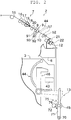
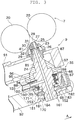
- FIG. 3 is a cross-sectional view illustrating a normal state in which a spindle 24 is located in proximity to a needle holder 25 in the spinning device 9.
- FIG. 4 is a cross-sectional perspective view illustrating the spindle 24 and a structure for supporting the spindle 24.
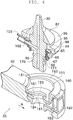
- FIG. 5 is a cross-sectional view illustrating a maintenance state in which the spindle 24 is located away from the needle holder 25.
- the spinning device 9 of the present embodiment includes a spinning nozzle 23 and a spindle unit (hollow guide shaft unit) 35.
- the spinning nozzle 23 includes the needle holder (fiber guiding section) 25, and a nozzle block (nozzle member) 26 to which the needle holder 25 is attached.
- the needle holder 25 and the nozzle block 26 are supported by a nozzle supporting arm 91 (see FIG. 2 ) attached to the frame 6 of the fine spinning machine 1.
- the needle holder 25 is provided with a guiding hole 27 adapted to introduce the fiber bundle 8 drafted by the draft device 7.
- the needle holder 25 holds a needle 28.
- a tip-end of the needle 28 is located in a path through which the fiber bundle 8 discharged from the guiding hole 27 to the downstream is fed.
- a circular hole 29 is formed in the nozzle block 26 at a position located downstream of the needle holder 25.
- a tip-end portion 30 of the spindle (hollow guide shaft body) 24 of the spindle unit 35 is inserted in the circular hole 29 with an axial center thereof aligned with an axial center of the circular hole 29.
- a predetermined gap is formed between an end face of the tip-end portion 30 of the spindle 24 and the needle holder 25, and a spinning chamber 31 is formed at such a portion.
- a tip-end of the needle 28 projects into the spinning chamber 31 to face the tip-end portion 30 of the spindle 24.
- a substantially cylindrical whirling airflow generating chamber 32 is formed between the circular hole 29 and the tip-end portion 30.
- a plurality of whirling airflow generating nozzles 41 are formed in the nozzle block 26, and an end of each of the whirling airflow generating nozzles 41 is opened to the spinning chamber 31.
- Each of the whirling airflow generating nozzles 41 is an elongate hole (nozzle hole) formed in the nozzle block 26 so as to connect to an inner wall of the spinning chamber 31 in a tangent direction and to be inclined towards downstream in the yarn feeding direction.
- the whirling airflow generating nozzle 41 injects compressed air supplied from a compressed air source (not illustrated) to the spinning chamber 31, and causes whirling airflow to be generated in the spinning chamber 31 in a counterclockwise direction, for example, when seen in an advancing direction of the fiber bundle 8. Accordingly, twists are applied to the fiber bundle 8.
- the whirling airflow flows spirally along the whirling airflow generating chamber 32 formed around the tip-end portion 30 of the spindle 24. Thereafter, the whirling airflow is discharged to the outside of the spinning device 9 via a discharge path formed inside the nozzle supporting arm 91.
- the spindle unit 35 includes the spindle 24 and a holder attachment 151 adapted to support the spindle 24.
- a fiber passage (fiber bundle passage) 85 is formed in the spindle 24 as an elongate hole along the axial center of the spindle 24.
- a hole connected to the fiber passage 85 is opened at the tip-end portion 30 of the spindle 24.
- the fiber bundle 8 twisted in the spinning chamber 31 is inserted into the hole of the tip-end portion 30, and then fed downstream to pass through an inside of the fiber passage 85.
- the spindle 24 is fixed while being inserted to a conical shaft body holding member 87 for positioning the spindle 24.
- the shaft body holding member 87 is formed as a conical member having a shaft hole, and a flange 88 is formed at an outer periphery thereof.
- a ring-shaped first contacting surface 95 is formed at a portion of the flange 88.
- a cylindrical second contacting surface 96 arranged perpendicular to the first contacting surface 95 is formed in the shaft body holding member 87.
- a ring-shaped flat first positioning surface 97 is formed on a downstream end surface of the tip-end portion of the nozzle supporting arm 91.
- An attachment hole 94 is formed on the inner side of the first positioning surface 97.
- a cylindrical second positioning surface 98 is formed on an inner peripheral surface of the attachment hole 94.
- the first positioning surface 97 and the second positioning surface 98 function as a positioning section for precisely positioning the tip-end portion 30 of the spindle 24 with respect to the needle holder 25.
- the spindle 24 can be accurately positioned with respect to the spinning nozzle 23 (the needle holder 25 and the nozzle block 26).
- the shaft body holding member 87 is not fixed to the nozzle supporting arm 91 with a bolt or the like, and the conical portion is merely inserted into the attachment hole 94. Therefore, by moving the shaft body holding member 87 from the attachment hole 94, the spindle 24 can be easily detached from the nozzle supporting arm 91 (see FIG. 5 ). As a result, a maintenance operation of removing the fibers clogged in the spinning chamber 31, the whirling airflow generating chamber 32, or the like, or detaching the spindle 24 to replace with a new one can be easily carried out.
- a compressed air introducing hole 102 is formed in the spindle 24 for introducing compressed air into the fiber passage 85.
- the compressed air introducing hole 102 is connected to a supply source (not illustrated) of the compressed air through a supplying tube 103 connected to the spindle 24.
- the fiber passage 85 is formed to axially pass through a center portion of the spindle 24.
- the fiber bundle 8 that has passed through the fiber passage 85 is discharged from the spindle 24 as the spun yarn 10.
- a receiving rubber (movement restricting section) 65 is fixed to the outer side of the spindle 24.
- the receiving rubber 65 is a rubber member, and can elastically deform.
- the receiving rubber 65 is formed in a ring shape, but a cutout for passing the supplying tube 103 of the compressed air is provided at one part of the receiving rubber 65.
- the receiving rubber 65 is provided entirely around the outer side of the spindle 24 by 360 degrees and is in close contact with the outer peripheral surface of the spindle 24.
- a first ring portion 66 and a second ring portion 67 serving as a first restricting portion projecting radially outward and a third ring portion 68 serving as a second restricting portion projecting to the downstream are integrally formed to constitute the receiving rubber 65.
- the first ring portion 66 and the second ring portion 67 project in a direction parallel to each other, and a ring-shaped groove is formed therebetween.
- the spindle 24 is attached to a spindle arm (supporting section) 92 attached to the frame 6 of the fine spinning machine 1.
- a substantially cylindrical attachment attaching portion 111 is formed on the tip-end of the spindle arm 92.
- the attachment attaching portion 111 is formed in a hollow shape.
- a large through-hole is formed at a bottom of the attachment attaching portion 111.
- the holder attachment 151 adapted to attach the spindle 24 is attached to an interior of the attachment attaching portion 111.
- the holder attachment 151 includes a holder main body (base section) 152, and a lock member (coupling section) 153 slidably attached to a bottom of the holder main body 152.
- a base end portion of the spindle arm 92 is supported by the frame 6 so as to be swingable about a swing shaft 93 illustrated in FIG. 2 . Therefore, by swinging the spindle arm 92 with the spindle 24 attached to the tip-end of the spindle arm 92 via the holder attachment 151, a normal state (first state, FIG. 3 ) in which the spindle 24 is located close to the needle holder 25 and a maintenance state (second state, FIG. 5 ) in which the spindle 24 is located away from the needle holder 25 can be switched. In such switching, the spindle 24 moves in an arcuate path with the swing shaft 93, which is a supporting shaft of the spindle arm 92, as a center.
- Such swinging of the spindle arm 92 (the switching between the normal state and the maintenance state) can be realized, for example, by using a spring force, or by driving an air cylinder or the like.
- the holder main body 152 is formed in a cup shape opened to the upstream, and a circular accommodation concave 160 is formed inside the holder main body 152.
- the receiving rubber 65 attached to the spindle 24 can be accommodated in the accommodation concave 160.
- the bottom of the holder main body 152 is double-bottomed, and a flat plate-like lock main body 181 of the lock member 153 is inserted to a gap formed between the double-bottom.
- a circular insertion hole 161 is formed to penetrate through the bottom of the holder main body 152.
- a downstream end of the spindle 24 (hereinafter sometimes referred to as an inserting portion 170) can be inserted to the insertion hole 161.
- a ring groove 171 is annularly formed on an outer peripheral surface of the inserting portion 170.
- a material of the lock member 153 is synthetic resin, and a push button section (decoupling operation section) 182 and a spring section (displacement-force generating section) 183 are integrally formed with respect to the flat plate-like lock main body 181.
- the lock main body 181 is attached to the bottom of the holder main body 152 in a manner that the lock main body 181 can be reciprocated at a predetermined stroke.
- a lock hole 184 is formed through the lock main body 181 at a position substantially corresponding to the insertion hole 161.
- a peripheral edge portion of the lock hole 184 can be inserted into the ring groove 171 formed in the inserting portion 170 of the spindle 24.
- the push button section 182 and the spring section 183 are both structured as a rib rising perpendicularly from an upper surface (upstream surface) near an end in a longitudinal direction of the lock main body 181.
- the surface of the push button section 182 is exposed to the outside, so that the operator can push the push button section 182 to slide the lock member 153.
- the spring section 183 is formed as a slightly-thin rib made of synthetic resin. By applying a lateral (direction perpendicular to the travelling direction of the fiber bundle 8) force upon the upper end of the spring section 183, the spring section 183 can be elastically deformed.
- the upper end (upstream end) of the spring section 183 makes contact with the outer peripheral surface of the holder main body 152.
- the spring section 183 is elastically deformed by the upper end of the spring section 183 being pushed by the outer peripheral surface of the holder main body 152 in an A direction in FIG. 3 and FIG. 4 . Accordingly, an elastic restoring force is generated at the spring section 183, and the elastic restoring force acts as an urging force for moving the lock member 153 in the direction of an arrow A.
- This urging force can be used as a returning force of when the operator pushes the push button section 182.
- the urging force is also used as a force for displacing the tip-end portion 30 of the spindle 24 to one side (details will be described later).
- the operator While pushing the push button section 182 with the finger, the operator then inserts the inserting portion 170 of the spindle 24 to the insertion hole 161 and the lock hole 184 from above (upstream) and also inserts the receiving rubber 65 into the accommodation concave 160.
- the lock member 153 moves in the direction of the arrow A by the restoring force of the spring section 183, and the edge of the lock hole 184 formed in the lock main body 181 projects out from the inner wall of the insertion hole 161 to enter the ring groove 171 formed in the inserting portion 170.
- An inner diameter of the insertion hole 161 formed in the holder main body 152 is formed to be slightly greater than an outer diameter of the downstream end of the spindle 24 (the inserting portion 170) to be inserted to the insertion hole 161, and a play of a certain extent in a radial direction of the spindle 24 is ensured.
- a width of the ring groove 171 formed in the inserting portion 170 is formed to be slightly greater than a thickness of the lock main body 181 to be inserted to the ring groove 171, and a play in an axial direction is also ensured.
- the ring-shaped receiving rubber 65 to be arranged between the holder main body 152 and the spindle 24 can be elastically deformed.
- the spindle 24 is not completely restricted (positioned) and can move with respect to the holder main body 152 within a range of the play (moderate restriction).
- the spindle 24 is allowed to move, although by a slight stroke, in the radial direction and in the axial direction, and furthermore, the spindle 24 can move to tilt its axis.
- the tip-end portion 30 of the spindle 24 can also move within a prescribed range and can also be tilted.
- the receiving rubber 65 arranged between the spindle 24 and the holder main body 152 elastically deforms in accordance therewith, and generates the restoring force to return the movement of the spindle 24.
- the first ring portion 66 and the second ring portion 67 mainly generate the elastic force to return the movement.
- the third ring portion 68 mainly generates the elastic force to return the movement.
- the spindle 24 in a state where no force is applied on the spindle 24, the spindle 24 is held at a position where the axial center thereof substantially coincides with the axial center of the accommodation concave 160 of the holder main body 152.
- the elastic deformation of the spring section 183 in the lock member 153 is not completely released even in a state where the spindle 24 is attached to the holder attachment 151 as illustrated in Fig 5 .
- the elastic restoring force of the spring section 183 is not lost. Since the lock main body 181 is pulled by the elastic restoring force of the spring section 183, the base end portion of the spindle 24 is pushed in the direction of the arrow A by the inner peripheral surface of the lock hole 184 formed in the lock main body 181. In other words, in the state of FIG. 5 , the elastic restoring force of the spring section 183 acts as a force in the direction of the arrow A on the inserting portion 170 of the spindle 24.
- the spindle 24 tilts like a see-saw with a middle portion in the axial direction (around where the receiving rubber 65 is arranged) as a supporting point, and the tip-end portion 30 is displaced by a slight distance in the direction of a thick arrow in FIG. 5 .
- the spring section 183 has a function of generating the force for displacing the tip-end portion 30 of the spindle 24 in a predetermined direction.
- the position of the tip-end portion 30 of the spindle 24 can be effectively stabilized by the force generated by the spring section 183.
- the spindle 24 may flutter due to the influence of vibration and the like, and the position of the tip-end portion 30 may become unstable.
- the fluttering of the spindle 24 due to the vibration and the like can be weakened to a certain extent by the receiving rubber 65.
- the spindle 24 is constantly pressed down so that the tip-end portion 30 is displaced in a predetermined direction by the force of the spring section 183, and a direction as well as a magnitude of the force of the spring section 183 are mostly constant. Therefore, the holder main body 152 can effectively suppress the fluttering of the spindle 24, and can hold the tip-end portion 30 of the spindle 24 in an extremely stable manner at a displaced position.
- the tip-end portion 30 of the spindle 24 is displaced towards the swing shaft 93 illustrated in FIG. 2 .
- This structure is extremely advantageous in a structure in which the spindle 24 needs to be moved in an arcuate path (not linear path) with the swing shaft 93 as the center when positioning the spindle 24 with respect to the spinning nozzle 23 (the needle holder 25) as in the present embodiment.
- the spindle 24 needs to be moved in an arcuate path (not linear path) with the swing shaft 93 as the center when positioning the spindle 24 with respect to the spinning nozzle 23 (the needle holder 25) as in the present embodiment.
- the tip-end portion 30 of the spindle 24 since the tip-end portion 30 of the spindle 24 is displaced to approach the spinning nozzle 23, even when the spindle 24 moves on the arcuate path, the tip-end portion 30 of the spindle 24 can be smoothly inserted into the nozzle block 26 without colliding with the nozzle block 26 to smoothly shift the spindle 24 to the state of FIG. 3 .
- the spindle arm 92 is swung towards the nozzle supporting arm 91, and the conical portion of the shaft body holding member 87 fixed to the spindle 24 is inserted into the attachment hole 94 formed in the nozzle supporting arm 91.
- the fluttering of the tip-end portion 30 of the spindle 24 is effectively prevented as described above. Therefore, the spindle 24 can be smoothly inserted into the attachment hole 94 without the tip-end portion 30 colliding with other members (e.g., the nozzle block 26) during the movement of the spindle 24.
- the spindle 24 is accurately positioned with respect to the spinning nozzle 23 (the needle holder 25).
- the state of FIG. 3 is realized in such a manner, and the spinning device 9 can perform spinning.
- the spindle arm 92 is swung from the state of FIG. 3 to release the positioning of the spindle 24 to achieve the state of FIG. 5 .
- the push button section 182 is then pushed to move the lock member 153 to release the lock main body 181 from the ring groove 171.
- the spindle 24 is then gripped and pulled upward to detach the spindle 24 from the holder attachment 151 at the tip-end of the spindle arm 92.
- a mechanical coupling state of the spindle 24 and the holder main body 152 is decoupled by one-action of simply pushing the push button section 182, and hence the maintenance workability is excellent.
- the inner bottom surface (hereinafter sometimes referred to as a supporting surface) of the accommodation concave 160 formed in the holder main body 152 supports the base end portion of the spindle 24.
- This inner bottom surface has a predetermined inclination, and the spindle 24 is inclined at a predetermined angle when the spindle 24 is supported.
- other types of holder attachment can be attached to the attachment attaching portion 111 provided at the tip-end of the spindle arm 92.
- Such a holder attachment may be formed such that the direction in which the accommodation concave 160 is formed (i.e., direction of the supporting surface) is slightly different from that of the holder attachment 151.
- the direction in which the spindle 24 is supported in the state of FIG. 5 (moreover, the movable range of the tip-end portion 30 of the spindle 24) can be variously changed. Accordingly, various layouts of the spindle 24 required according to a type of a yarn to be spun can be easily realized.
- the spindle unit 35 of the spinning device 9 includes the spindle 24, the holder main body 152, the lock member 153, and the spring section 183.
- the spindle 24 includes the tip-end portion 30 adapted to receive an insert of the twisted fiber bundle 8, and the fiber passage 85 adapted to receive a passing of the fiber bundle 8 inserted from the tip-end portion 30.
- the holder main body 152 supports the spindle 24.
- the lock member 153 is adapted to mechanically couple the spindle 24 with the holder main body 152.
- the tip-end portion 30 of the spindle 24 can move within a predetermined range.
- the spring section 183 is adapted to generate a force in a direction of the arrow A to act upon the lower part of the spindle 24 (the inserting portion 170) so as to displace the tip-end portion 30 towards one side within the movable range (i,e., side illustrated with the thick arrow in FIG. 5 ).
- the spindle 24 can be mechanically coupled with the holder main body 152 by the lock member 153, and in this state, the holder main body 152 can hold the spindle 24 with the position of the tip-end portion 30 of the spindle 24 provided with a certain degree of freedom of movement. Therefore, by positioning the spindle 24 with the first contacting surface 95 and the second contacting surface 96 (the first positioning surface 97 and the second positioning surface 98) without decoupling such a mechanical coupling state (e. g. , FIG. 3 ), the tip-end portion 30 of the spindle 24 can be precisely repositioned, and the quality of the spun yarn 10 can be improved. Furthermore, even in the state of FIG.
- the tip-end portion 30 of the spindle 24 becomes movable with a simple structure of providing a play.
- the spring section 183 functions as an elastic member that generates an elastic restoring force.
- the tip-end portion 30 of the spindle 24 can be displaced to one side with a stable force from the elastic member. Therefore, the position of the tip-end portion 30 of the spindle 24 can be reliably stabilized.
- the spindle unit 35 of the present embodiment includes the receiving rubber 65 provided between the spindle 24 and the holder main body 152 and adapted to generate a force against a movement of the spindle 24.
- the movement of the spindle 24 can be restricted by the receiving rubber 65, and the position of the tip-end portion 30 of the spindle 24 can be reliably stabilized.
- the receiving rubber 65 is a member capable of being elastically deformed.
- the spindle 24 tends to move by the influence of vibration and the like, the momentum at which the spindle 24 tends to move can be absorbed by the elastic deformation of the receiving rubber 65. As a result, the position of the tip-end portion 30 of the spindle 24 can be reliably stabilized.
- the receiving rubber 65 includes the first ring portion 66 and the second ring portion 67, as well as the third ring portion 68.
- the first ring portion 66 and the second ring portion 67 are adapted to restrict a movement of the spindle 24 in a direction substantially perpendicular to the travelling direction (radial direction) of the fiber bundle 8.
- the third ring portion 68 is adapted to restrict a movement of the spindle 24 in a direction substantially parallel to the travelling direction (axial direction) of the fiber bundle 8.
- the spindle 24 and the receiving rubber 65 are provided detachably with respect to the holder main body 152.
- the first ring portion 66, the second ring portion 67, and the third ring portion 68 of the receiving rubber 65 are all provided capable of making contact with the holder main body 152.
- the receiving rubber 65 includes a concave (ring-shaped groove) to form a gap with respect to the holder main body 152.
- the contacting area between the receiving rubber 65 and the holder main body 152 can be reduced by the amount of the concave, whereby the receiving rubber 65 can be easily attached or detached with respect to the holder main body 152.
- the receiving rubber 65 is provided in a ring-shape entirely around an outer peripheral surface of the spindle 24.
- the fluttering of the spindle 24 in the radial direction can be satisfactorily and reliably suppressed.
- the spindle unit 35 of the present embodiment includes the push button section 182 adapted to decouple by one-action the state in which the spindle 24 is mechanically coupled with the holder main body 152 via the lock member 153.
- the spindle 24 can be detached from the holder main body 152 by a simple operation of merely pushing the push button section 182.
- the spinning device 9 of the present embodiment includes the spindle unit 35, the needle holder 25, the spindle arm 92, the first positioning surface 97, the second positioning surface 98, and the nozzle block 26.
- the needle holder 25 is provided to face the spindle 24 and adapted to guide the fiber bundle 8 to the fiber passage 85.
- the spindle arm 92 is adapted to support the spindle 24, and to enable switching between the normal state ( FIG. 3 ) in which the spindle 24 is located close to the needle holder 25 and the maintenance state ( FIG. 5 ) in which the spindle 24 is located away from the needle holder 25.
- the first positioning surface 97 and the second positioning surface 98 are adapted to position the tip-end portion 30 of the spindle 24 under the normal state with respect to the needle holder 25.
- the nozzle block 26 is adapted to form the spinning chamber 31 between the nozzle block 26 and the spindle 24 under the normal state ( FIG. 3 ), and to inject compressed air from the nozzle hole (hole of the whirling airflow generating nozzle 41) that opens into the spinning chamber 31 to generate whirling airflow to be acted upon the fiber bundle 8 in the spinning chamber 31.
- the holder main body 152 can hold the spindle 24 with the position of the tip-end portion 30 of the spindle 24 having a certain degree of freedom of movement under the maintenance state ( FIG. 5 ).
- the spindle 24 is positioned by the first positioning surface 97 and the second positioning surface 98. Accordingly, the tip-end portion 30 of the spindle 24 can be accurately positioned with respect to the needle holder 25, and the quality of the spun yarn 10 can be improved.
- the spindle arm 92 can be switched between the normal state ( FIG. 3 ) and the maintenance state ( FIG. 5 ).
- the spring section 183 is adapted to generate a force to act upon the lower part of the spindle 24 (the inserting portion 170) to displace the tip-end portion 30 of the spindle 24 within the movable range to approach a center of the arcuate path (i.e., the swing shaft 93 illustrated in FIG. 2 ).
- the spindle 24 can be smoothly moved without the tip-end portion 30 of the spindle 24 interfering with other members.
- the inner bottom surface of the accommodation concave 160 of the holder main body 152 is provided as the supporting surface to support the spindle 24 from a base-end portion substantially at a prescribed inclination angle.
- the holder main body 152 (the holder attachment 151) can be replaced with another holder main body 152 having the supporting surface with a different inclination angle.
- the fine spinning machine 1 of the present embodiment includes the above-described spinning device 9, and the winding device 13.
- the winding device 13 is adapted to wind the spun yarn 10, which has been spun by the spinning device 9, into the package 45.
- the fine spinning machine 1 is provided in which the replacement operation of the spindle 24 is easy and the package 45 of a high quality spun yarn 10 can be obtained.
- the push button section 182 may be changed to a structure including a lever or the like capable of a pulling operation.
- a member without the needle 28 e.g. , a block-shaped member formed with the guiding hole 27
- a member without the needle 28 e.g. , a block-shaped member formed with the guiding hole 27
- the fiber guiding section may be adopted for the fiber guiding section.
- a delivery roller to be rotationally driven and a nip roller to be pushed against the delivery roller may be arranged, and the spun yarn 10 can be sandwiched between the delivery roller and the nip roller to be fed downstream.
- the spring section 183 and the push button section 182 are integrally formed with the lock member 153, but the spring section 183 and the push button section 182 may be separate members from the lock member 153.
- a spring made of metal and not synthetic resin e.g., a coil spring or a plate spring may be used in place of the spring section 183.
- the spindle 24 is attached to the holder attachment 151, which is attached to the tip-end of the spindle arm 92.
- the spindle 24 may be directly attached to the tip-end of the spindle arm 92.
- the switching between the normal state of FIG. 3 and the maintenance state of FIG. 5 is carried out by moving the spindle 24 with the swinging of the spindle arm 92.
- the switching between these states can be realized by moving the needle holder 25 side (the nozzle block 26 side) with the swinging of the nozzle supporting arm 91.
- the lock member 153, the push button section 182, the spring section 183, and the like are configured as one part of the holder attachment 151.
- the lock member 153, the push button section 182, and the like may be arranged on the spindle arm 92 side, and only the holder main body 152 may be attached to the spindle arm 92 in a replaceable manner.
- the needle holder 25 and the nozzle block 26 are separate components.
- the needle holder 25 and the nozzle block 26 may be formed as one component in which the fiber guiding section and the nozzle member are integrated.
Description
- The present invention mainly relates to a structure of a hollow guide shaft unit used in an air-jet spinning device adapted to generate a spun yarn by twisting a fiber bundle with an action of airflow.
-
Japanese Unexamined Patent Publication No. 7-126924 Japanese Unexamined Patent Publication No. 7-126924 Japanese Unexamined Patent Publication No. 7-126924 -
JP 2011-038210 A - An object of the present invention is to provide an air-jet spinning device capable of smoothly positioning a hollow guide shaft body and improving workability in replacing the hollow guide shaft body.
- This object is achieved by a hollow guide shaft unit according to
claim 1. - In the above-described air-jet spinning device, the hollow spindle is preferably arranged at an accurate position in order to improve quality of the spun yarn to be produced. In the air-jet spinning device, in order to produce many types of yarns, there is a need to replaceably provide the hollow spindle.
- However, in the structure of
Japanese Unexamined Patent Publication No. 7-126924 - According to a first aspect of the present invention, a hollow guide shaft unit includes a hollow guide shaft body, a base section, a coupling section, and a displacement-force generating section. The hollow guide shaft body includes a tip-end portion adapted to receive an insert of a twisted fiber bundle, and a fiber bundle passage adapted to receive a passing of the fiber bundle inserted from the tip-end portion. The base section is adapted to support the hollow guide shaft body. The coupling section is adapted to mechanically couple the hollow guide shaft body with the base section. The displacement-force generating section is adapted to generate a force to act upon the hollow guide shaft body so as to displace the tip-end portion of the hollow guide shaft body towards one side within a movable range under a state in which the hollow guide shaft body is mechanically coupled with the base section via the coupling section, the movable range being a range in which the tip-end portion of the hollow guide shaft body can be moved. A play is formed around the hollow guide shaft body under a state in which the hollow guide shaft body is mechanically coupled with the base section via the coupling section. This play enables movement of the tip-end portion of the hollow guide shaft body.
- Accordingly, the hollow guide shaft body can be mechanically coupled with the base section by the coupling section, and the hollow guide shaft body can be held by the base section under a state in which a position of the tip-end portion of the hollow guide shaft body is provided with a certain degree of freedom of movement. Therefore, the tip-end portion of the hollow guide shaft body can be precisely repositioned without decoupling the mechanical coupling state, and the quality of the yarn to be spun can be improved. Furthermore, even if the precise positioning is not carried out, since a force of the displacement-force generating section is applied so as to displace the tip-end portion of the hollow guide shaft body towards one side within the movable range, the position of the tip-end portion of the hollow guide shaft body does not greatly fluctuate even with an occurrence of small vibration. Therefore, excessive fluttering of the tip-end portion of the hollow guide shaft body can be prevented, and the workability of maintenance work can be improved. The tip-end portion of the hollow guide shaft body becomes movable with a simple structure of providing a play.
- In the above hollow guide shaft unit, the displacement-force generating section is preferably an elastic member that generates an elastic restoring force.
- Accordingly, the tip-end portion of the hollow guide shaft body can be displaced towards one side with a stable force from the elastic member. As a result, the position of the tip-end portion of the hollow guide shaft body can be reliably stabilized.
- The above hollow guide shaft unit preferably includes a movement restricting section provided between the hollow guide shaft body and the base section and adapted to generate a force against a movement of the hollow guide shaft body.
- Accordingly, the movement of the hollow guide shaft body can be restricted by the restricting section, and the position of the tip-end portion of the hollow guide shaft body can be reliably stabilized.
- In the above hollow guide shaft unit, the movement restricting section is preferably a member capable of being elastically deformed.
- Accordingly, even if the hollow guide shaft body tends to move by the influence of vibration or the like, momentum at which the hollow guide shaft body tends to move can be absorbed by the elastic deformation of the movement restricting section. As a result, the position of the tip-end portion of the hollow guide shaft body can be reliably stabilized.
- In the above hollow guide shaft unit, the movement restricting section includes a first restricting portion and a second restricting portion. The first restricting portion is adapted to restrict a movement of the hollow guide shaft body in a direction substantially perpendicular to the fiber bundle passage. The second restricting portion is adapted to restrict a movement of the hollow guide shaft body in a direction substantially parallel to the fiber bundle passage.
- Accordingly, the excessive fluttering of the hollow guide shaft body can be effectively prevented.
- In the above hollow guide shaft unit, the first restricting portion and the second restricting portion are provided capable of making contact with the base section. The movement restricting section includes a concave to form a gap with respect to the base section. The hollow guide shaft body and the movement restricting section are provided detachably with respect to the base section.
- Accordingly, a contacting area between the movement restricting section and the base section can be reduced by the amount of the concave, and the movement restricting section can be easily attached or detached with respect to the base section.
- In the above hollow guide shaft unit, the movement restricting section is preferably provided entirely around an outer peripheral surface of the hollow guide shaft body.
- Accordingly, fluttering in a radial direction of the hollow guide shaft body can be satisfactorily and reliably suppressed.
- The above hollow guide shaft unit preferably includes a decoupling operation section adapted to decouple by one-action the state in which the hollow guide shaft body is mechanically coupled with the base section via the coupling section.
- Accordingly, the above hollow guide shaft body can be detached from the base section with a simple operation of one-action.
- According to a second aspect of the present invention, an air-jet spinning device includes the hollow guide shaft unit, a fiber guiding section, a supporting section, a positioning section, and a nozzle member. The fiber guiding section is provided to face the hollow guide shaft body and adapted to guide the fiber bundle to the fiber bundle passage. The supporting section is adapted to support at least one of the fiber guiding section and the hollow guide shaft body and to enable switching between a first state in which the hollow guide shaft body is located close to the fiber guiding section and a second state in which the hollow guide shaft body is located away from the fiber guiding section. The positioning section is adapted to determine a position of the tip-end portion of the hollow guide shaft body under the first state with respect to the fiber guiding section. The nozzle member is adapted to form a spinning chamber between the nozzle member and the hollow guide shaft body under the first state, and to inject compressed air from at least one nozzle hole that opens into the spinning chamber to generate whirling airflow in the spinning chamber to be acted upon the fiber bundle.
- Accordingly, under the second state, the base section can hold the hollow guide shaft body with the position of the tip-end portion of the hollow guide shaft body having a certain degree of freedom of movement. Under the first state, the tip-end portion of the hollow guide shaft body is accurately positioned with respect to the fiber guiding section by the positioning section. As a result, the quality of the yarn to be spun by the air-jet spinning device can be improved.
- In the above air-jet spinning device, the supporting section is adapted to switch between the first state and the second state by moving at least one of the hollow guide shaft body and the fiber guiding section so that the hollow guide shaft body moves in an arcuate path with respect to the fiber guiding section. The displacement-force generating section is adapted to generate a force to be applied to the hollow guide shaft body to displace the tip-end portion of the hollow guide shaft body within the movable range to approach a center of the arcuate path.
- Accordingly, with the movement of the hollow guide shaft body in the arcuate path with respect to the fiber guiding section when switching between the first state and the second state, the tip-end portion of the hollow guide shaft body can be smoothly moved without interfering with other members.
- In the above air-jet spinning device, the base section includes a supporting surface adapted to support the hollow guide shaft body from a base-end portion at a prescribed inclination angle. The base section can be replaced with another base section having the supporting surface with a different inclination angle.
- Accordingly, various layouts of the hollow guide shaft body demanded in the air-jet spinning device can be easily realized.
- According to a third aspect of the present invention, an air-jet spinning device includes a hollow guide shaft unit and a nozzle member. The hollow guide shaft unit includes a hollow guide shaft body, a base section, a coupling section, a decoupling operation section, a displacement-force generating section, and a movement restricting section. The hollow guide shaft body includes a tip-end portion adapted to receive an insert of a twisted fiber bundle, and a fiber bundle passage adapted to receive a passing of the fiber bundle inserted from the tip-end portion. The base section is adapted to support the hollow guide shaft body. The coupling section is adapted to mechanically couple the hollow guide shaft body with the base section. The decoupling operation section is adapted to decouple by one-action the state in which the hollow guide shaft body is mechanically coupled with the base section via the coupling section. The displacement-force generating section is an elastic member that is adapted to generate a force to act upon the hollow guide shaft body so as to displace the tip-end portion of the hollow guide shaft body towards one side within a movable range under a state in which the hollow guide shaft body is mechanically coupled with the base section via the coupling section, the movable range being a range in which the tip-end portion of the hollow guide shaft body can be moved. The movement restricting section is a member provided between the hollow guide shaft body and the base section and entirely around an outer peripheral surface of the hollow guide shaft body, and is capable of being elastically deformed to generate a force against a movement of the hollow guide shaft body. The nozzle member is adapted to form a spinning chamber between the nozzle member and the hollow guide shaft body of the hollow guide shaft unit, and to inject compressed air from at least one nozzle hole that opens into the spinning chamber to generate whirling airflow in the spinning chamber to be acted upon the fiber bundle.
- Accordingly, the hollow guide shaft body can be mechanically coupled with the base section by the coupling section, and the hollow guide shaft body can be held by the base section under the state in which the position of the tip-end portion of the hollow guide shaft body is provided with a certain degree of freedom of movement. Therefore, the tip-end portion of the hollow guide shaft body can be precisely repositioned without decoupling the mechanical coupling state, and the quality of the yarn to be spun by the air-jet spinning device can be improved. Furthermore, even if the precise positioning is not carried out, since the elastic force of the displacement-force generating section is stably applied to displace the tip-end portion of the hollow guide shaft body towards one side within the movable range, the position of the tip-end portion of the hollow guide shaft body does not greatly fluctuate even with an occurrence of small vibration. Furthermore, the movement of the hollow guide shaft body in the radial direction is satisfactorily and reliably suppressed by the elastic deformation of the movement restricting section. Therefore, excessive fluttering of the tip-end portion of the hollow guide shaft body can be prevented and workability of maintenance work can be improved. Moreover, the hollow guide shaft body can be easily detached from the base section by operating the decoupling operation section with one-action.
- According to a fourth aspect of the present invention, a spinning machine includes the above-described air-jet spinning device, and a winding section. The winding section is adapted to wind a spun yarn, which has been spun by the air-jet spinning device, into a package.
- Accordingly, a spinning machine is provided in which the hollow guide shaft body can be easily replaced, and a high quality yarn can be obtained.
-
-
FIG. 1 is a front view illustrating an overall structure of a fine spinning machine according to one embodiment of the present invention; -
FIG. 2 is a longitudinal cross-sectional view of the fine spinning machine; -
FIG. 3 is a cross-sectional view illustrating a normal state in which a spindle is located in proximity to a needle holder in the spinning device; -
FIG. 4 is a cross-sectional perspective view illustrating the spindle and a structure for supporting the spindle; and -
FIG. 5 is a cross-sectional view illustrating a maintenance state in which the spindle is located away from the needle holder. - A fine spinning machine (spinning machine) serving as a textile machine according to one embodiment of the present invention will be described with reference to the drawings. "Upstream" and "downstream" respectively refer to upstream and downstream in a travelling direction of a yarn or a fiber at the time of spinning.
FIG. 1 is a front view illustrating an overall structure of afine spinning machine 1 according to one embodiment of the present invention.FIG. 2 is a longitudinal cross-sectional view of thefine spinning machine 1. - The
fine spinning machine 1 as a textile machine illustrated inFIG. 1 includes a plurality of spinning units (yarn processing units) 2 arranged in line, amain control device 60, ayarn joining cart 3, ablower box 4, and amotor box 5. - The
spinning unit 2 carries out spinning with respect to a suppliedsliver 15 to form apackage 45 around which a spunyarn 10 is wound. As illustrated inFIG. 1 , each spinningunit 2 includes adraft device 7, a spinning device (air-jet spinning device) 9, a yarnslack eliminating device 12, and a winding device (winding section) 13, arranged in this order from the upstream to the downstream. - The
draft device 7 is arranged in proximity to an upper end of aframe 6 of thefine spinning machine 1. Thedraft device 7 drafts thesliver 15 into a fiber bundle 8 by a rotation of a plurality of rollers. Thespinning device 9 carries out the spinning by twisting the fiber bundle 8 fed from thedraft device 7 by an action of whirling airflow. The spunyarn 10 produced by thespinning device 9 passes through ayarn clearer 52 adapted to detect a defect of the spunyarn 10, and is then fed to the yarnslack eliminating device 12. The spunyarn 10 that passed the yarnslack eliminating device 12 is wound by the windingdevice 13 into thepackage 45. The detailed structure of thespinning unit 2 will be described later. - The
main control device 60 collectively manages each component of thefine spinning machine 1. Themain control device 60 includes a display 61 and anoperation section 62. An operator can check a state of eachspinning unit 2 with the display 61 or can instruct a change in a spinning parameter with respect to at least one or all of thespinning units 2 by operating theoperation section 62. Themain control device 60 can also control and manage theyarn joining cart 3 and theblower box 4, for example, other than thespinning unit 2. - The
yarn joining cart 3 includes a splicer (yarn joining device) 43, asuction pipe 44, and asuction mouth 46. Thefine spinning machine 1 includes a rail (not illustrated), and theyarn joining cart 3 can move along the rail in a direction parallel to the direction in which thespinning units 2 are arranged. When yarn breakage or yarn cut occurs during spinning in aspinning unit 2, theyarn joining cart 3 travels to therelevant spinning unit 2 and stops at the relevant position. Theyarn joining cart 3 then catches a yarn end from thespinning device 9 with thesuction pipe 44 and also catches a yarn end from the windingdevice 13 with thesuction mouth 46. Theyarn joining cart 3 swings thesuction pipe 44 and thesuction mouth 46 to respectively guide the caught yarn end from thespinning device 9 and the caught yarn end from the windingdevice 13 to thesplicer 43. The yarn end from thespinning device 9 and the yarn end from the windingdevice 13 guided to thesplicer 43 are joined by thesplicer 43. The yarn end from thespinning device 9 and the yarn end from the windingdevice 13 are thereby joined, and thespinning unit 2 can resume the winding operation. - A blower serving as a negative pressure source (not illustrated) is provided in the
blower box 4. The blower is connected to eachspinning unit 2 through a duct (not illustrated), and can suck and remove yarn waste, fly waste, and the like generated by thespinning unit 2. - An electric motor (not illustrated), which is a common driving source for the plurality of spinning
units 2, is provided in themotor box 5. Power generated by the electric motor is used, for example, to drive some of rollers of thedraft device 7 or to drive atraverse rod 77, to be described later, in the windingdevice 13. - The
fine spinning machine 1 includes a doffing cart (not illustrated) adapted to doff the fully-wound package 45. The doffing cart can travel independently from theyarn joining cart 3. - Next, the
spinning unit 2 will be described in detail. As described above, thespinning unit 2 includes thedraft device 7, thespinning device 9, the yarnslack eliminating device 12, and the windingdevice 13. - As illustrated in
FIG. 2 , thedraft device 7 includes four pairs of rollers, i.e., a back roller pair 16, a third roller pair 17, a middle roller pair 19 provided with an apron belt 18, and afront roller pair 20. The rollers are driven by power from themotor box 5 or by power of electric motors (not illustrated) provided in eachspinning unit 2. Each roller pair is driven with a different rotation speed. As a result, thedraft device 7 can draft thesliver 15 supplied from the upstream to form the fiber bundle 8 and feed the fiber bundle 8 to thespinning device 9. - The
spinning device 9 is a so-called air-jet spinning device, and includes a whirling airflow generating nozzle arranged at a periphery of a path of the fiber bundle 8. Thespinning device 9 generates the whirling airflow at the periphery of the fiber bundle 8 by blowing compressed air from the whirling airflow generating nozzle, so that twists are applied to the fiber bundle 8, and the spunyarn 10 is produced at high speed. The detailed structure of thespinning device 9 will be described later. - The
yarn clearer 52 is arranged at a position slightly downstream of thespinning device 9. The spunyarn 10 spun by thespinning device 9 passes through theyarn clearer 52 before being wound by the yarnslack eliminating device 12. By monitoring a thickness of the travelling spunyarn 10, theyarn clearer 52 can detect a yarn defect of the spunyarn 10. Acutter 57 is arranged in proximity to theyarn clearer 52, and cuts the spunyarn 10 when theyarn clearer 52 detects the yarn defect. - The yarn
slack eliminating device 12 is adapted to eliminate the slackening of the spunyarn 10 between the spinningdevice 9 and the windingdevice 13, and apply an appropriate tension on the spunyarn 10. The yarnslack eliminating device 12 includes aslack eliminating roller 21 and ayarn hooking member 22. The description on the detailed structure of the yarnslack eliminating device 12 will be omitted, but the yarnslack eliminating device 12 winds and accumulates the spunyarn 10 around an outer periphery of theslack eliminating roller 21, and causes the accumulated spunyarn 10 to function as a buffer to absorb a fluctuation in tension of the spunyarn 10 and prevent slackening of the spunyarn 10. - The winding
device 13 includes acradle arm 71, a windingdrum 72, and atraverse device 75. - The
cradle arm 71 is supported to be swingable about a supportingshaft 70. Thecradle arm 71 can rotatably support a bobbin for winding the spunyarn 10. The windingdrum 72 is adapted to be driven while making contact with an outer peripheral surface of the bobbin or an outer peripheral surface of thepackage 45 formed by winding the spunyarn 10 around the bobbin. Thetraverse device 75 includes atraverse guide 76, to which the spunyarn 10 can be hooked. Thetraverse guide 76 is fixed to thetraverse rod 77 arranged horizontally across the plurality of spinningunits 2. The windingdrum 72 is driven by the electric motor (not illustrated) while reciprocating thetraverse rod 77, so that thepackage 45 making contact with the windingdrum 72 can be rotated and the spunyarn 10 can be wound into thepackage 45 while being traversed. - Next, a structure of the
spinning device 9 will be described in detail with reference toFIG. 3 to FIG. 5 .FIG. 3 is a cross-sectional view illustrating a normal state in which aspindle 24 is located in proximity to aneedle holder 25 in thespinning device 9.FIG. 4 is a cross-sectional perspective view illustrating thespindle 24 and a structure for supporting thespindle 24.FIG. 5 is a cross-sectional view illustrating a maintenance state in which thespindle 24 is located away from theneedle holder 25. - As illustrated in
FIG. 3 , thespinning device 9 of the present embodiment includes a spinningnozzle 23 and a spindle unit (hollow guide shaft unit) 35. - The spinning
nozzle 23 includes the needle holder (fiber guiding section) 25, and a nozzle block (nozzle member) 26 to which theneedle holder 25 is attached. Theneedle holder 25 and thenozzle block 26 are supported by a nozzle supporting arm 91 (seeFIG. 2 ) attached to theframe 6 of thefine spinning machine 1. As illustrated inFIG. 3 , theneedle holder 25 is provided with a guidinghole 27 adapted to introduce the fiber bundle 8 drafted by thedraft device 7. Theneedle holder 25 holds aneedle 28. A tip-end of theneedle 28 is located in a path through which the fiber bundle 8 discharged from the guidinghole 27 to the downstream is fed. - A
circular hole 29 is formed in thenozzle block 26 at a position located downstream of theneedle holder 25. A tip-end portion 30 of the spindle (hollow guide shaft body) 24 of thespindle unit 35 is inserted in thecircular hole 29 with an axial center thereof aligned with an axial center of thecircular hole 29. A predetermined gap is formed between an end face of the tip-end portion 30 of thespindle 24 and theneedle holder 25, and a spinningchamber 31 is formed at such a portion. A tip-end of theneedle 28 projects into the spinningchamber 31 to face the tip-end portion 30 of thespindle 24. A substantially cylindrical whirlingairflow generating chamber 32 is formed between thecircular hole 29 and the tip-end portion 30. - A plurality of whirling
airflow generating nozzles 41 are formed in thenozzle block 26, and an end of each of the whirlingairflow generating nozzles 41 is opened to the spinningchamber 31. Each of the whirlingairflow generating nozzles 41 is an elongate hole (nozzle hole) formed in thenozzle block 26 so as to connect to an inner wall of the spinningchamber 31 in a tangent direction and to be inclined towards downstream in the yarn feeding direction. - The whirling
airflow generating nozzle 41 injects compressed air supplied from a compressed air source (not illustrated) to the spinningchamber 31, and causes whirling airflow to be generated in the spinningchamber 31 in a counterclockwise direction, for example, when seen in an advancing direction of the fiber bundle 8. Accordingly, twists are applied to the fiber bundle 8. The whirling airflow flows spirally along the whirlingairflow generating chamber 32 formed around the tip-end portion 30 of thespindle 24. Thereafter, the whirling airflow is discharged to the outside of thespinning device 9 via a discharge path formed inside thenozzle supporting arm 91. - The
spindle unit 35 includes thespindle 24 and aholder attachment 151 adapted to support thespindle 24. A fiber passage (fiber bundle passage) 85 is formed in thespindle 24 as an elongate hole along the axial center of thespindle 24. A hole connected to thefiber passage 85 is opened at the tip-end portion 30 of thespindle 24. The fiber bundle 8 twisted in the spinningchamber 31 is inserted into the hole of the tip-end portion 30, and then fed downstream to pass through an inside of thefiber passage 85. - The
spindle 24 is fixed while being inserted to a conical shaftbody holding member 87 for positioning thespindle 24. - As illustrated in
FIG. 4 , the shaftbody holding member 87 is formed as a conical member having a shaft hole, and aflange 88 is formed at an outer periphery thereof. A ring-shaped first contactingsurface 95 is formed at a portion of theflange 88. A cylindrical second contactingsurface 96 arranged perpendicular to the first contactingsurface 95 is formed in the shaftbody holding member 87. As illustrated inFIG. 3 , a ring-shaped flatfirst positioning surface 97 is formed on a downstream end surface of the tip-end portion of thenozzle supporting arm 91. Anattachment hole 94 is formed on the inner side of thefirst positioning surface 97. A cylindricalsecond positioning surface 98 is formed on an inner peripheral surface of theattachment hole 94. Thefirst positioning surface 97 and thesecond positioning surface 98 function as a positioning section for precisely positioning the tip-end portion 30 of thespindle 24 with respect to theneedle holder 25. - By inserting a conical portion of the shaft
body holding member 87 to theattachment hole 94 of thenozzle supporting arm 91 from below, the first contactingsurface 95 is caused to make contact with thefirst positioning surface 97, and the second contactingsurface 96 is caused to make contact with thesecond positioning surface 98. Accordingly, thespindle 24 can be accurately positioned with respect to the spinning nozzle 23 (theneedle holder 25 and the nozzle block 26). - The shaft
body holding member 87 is not fixed to thenozzle supporting arm 91 with a bolt or the like, and the conical portion is merely inserted into theattachment hole 94. Therefore, by moving the shaftbody holding member 87 from theattachment hole 94, thespindle 24 can be easily detached from the nozzle supporting arm 91 (seeFIG. 5 ). As a result, a maintenance operation of removing the fibers clogged in the spinningchamber 31, the whirlingairflow generating chamber 32, or the like, or detaching thespindle 24 to replace with a new one can be easily carried out. - A compressed
air introducing hole 102 is formed in thespindle 24 for introducing compressed air into thefiber passage 85. The compressedair introducing hole 102 is connected to a supply source (not illustrated) of the compressed air through a supplyingtube 103 connected to thespindle 24. - The
fiber passage 85 is formed to axially pass through a center portion of thespindle 24. The fiber bundle 8 that has passed through thefiber passage 85 is discharged from thespindle 24 as the spunyarn 10. - At a position slightly downstream of the shaft
body holding member 87, a receiving rubber (movement restricting section) 65 is fixed to the outer side of thespindle 24. The receivingrubber 65 is a rubber member, and can elastically deform. The receivingrubber 65 is formed in a ring shape, but a cutout for passing the supplyingtube 103 of the compressed air is provided at one part of the receivingrubber 65. The receivingrubber 65 is provided entirely around the outer side of thespindle 24 by 360 degrees and is in close contact with the outer peripheral surface of thespindle 24. - A
first ring portion 66 and asecond ring portion 67 serving as a first restricting portion projecting radially outward and athird ring portion 68 serving as a second restricting portion projecting to the downstream are integrally formed to constitute the receivingrubber 65. Thefirst ring portion 66 and thesecond ring portion 67 project in a direction parallel to each other, and a ring-shaped groove is formed therebetween. - Next, a structure for supporting the
spindle 24 will be described. Thespindle 24 is attached to a spindle arm (supporting section) 92 attached to theframe 6 of thefine spinning machine 1. As illustrated inFIG. 4 , a substantially cylindricalattachment attaching portion 111 is formed on the tip-end of thespindle arm 92. Theattachment attaching portion 111 is formed in a hollow shape. A large through-hole is formed at a bottom of theattachment attaching portion 111. - The
holder attachment 151 adapted to attach thespindle 24 is attached to an interior of theattachment attaching portion 111. Theholder attachment 151 includes a holder main body (base section) 152, and a lock member (coupling section) 153 slidably attached to a bottom of the holdermain body 152. - A base end portion of the
spindle arm 92 is supported by theframe 6 so as to be swingable about aswing shaft 93 illustrated inFIG. 2 . Therefore, by swinging thespindle arm 92 with thespindle 24 attached to the tip-end of thespindle arm 92 via theholder attachment 151, a normal state (first state,FIG. 3 ) in which thespindle 24 is located close to theneedle holder 25 and a maintenance state (second state,FIG. 5 ) in which thespindle 24 is located away from theneedle holder 25 can be switched. In such switching, thespindle 24 moves in an arcuate path with theswing shaft 93, which is a supporting shaft of thespindle arm 92, as a center. Such swinging of the spindle arm 92 (the switching between the normal state and the maintenance state) can be realized, for example, by using a spring force, or by driving an air cylinder or the like. - As illustrated in
FIG. 4 , the holdermain body 152 is formed in a cup shape opened to the upstream, and a circular accommodation concave 160 is formed inside the holdermain body 152. The receivingrubber 65 attached to thespindle 24 can be accommodated in the accommodation concave 160. The bottom of the holdermain body 152 is double-bottomed, and a flat plate-like lockmain body 181 of thelock member 153 is inserted to a gap formed between the double-bottom. - A
circular insertion hole 161 is formed to penetrate through the bottom of the holdermain body 152. A downstream end of the spindle 24 (hereinafter sometimes referred to as an inserting portion 170) can be inserted to theinsertion hole 161. Aring groove 171 is annularly formed on an outer peripheral surface of the insertingportion 170. - A material of the
lock member 153 is synthetic resin, and a push button section (decoupling operation section) 182 and a spring section (displacement-force generating section) 183 are integrally formed with respect to the flat plate-like lockmain body 181. - The lock
main body 181 is attached to the bottom of the holdermain body 152 in a manner that the lockmain body 181 can be reciprocated at a predetermined stroke. Alock hole 184 is formed through the lockmain body 181 at a position substantially corresponding to theinsertion hole 161. A peripheral edge portion of thelock hole 184 can be inserted into thering groove 171 formed in the insertingportion 170 of thespindle 24. - The
push button section 182 and thespring section 183 are both structured as a rib rising perpendicularly from an upper surface (upstream surface) near an end in a longitudinal direction of the lockmain body 181. The surface of thepush button section 182 is exposed to the outside, so that the operator can push thepush button section 182 to slide thelock member 153. Thespring section 183 is formed as a slightly-thin rib made of synthetic resin. By applying a lateral (direction perpendicular to the travelling direction of the fiber bundle 8) force upon the upper end of thespring section 183, thespring section 183 can be elastically deformed. The upper end (upstream end) of thespring section 183 makes contact with the outer peripheral surface of the holdermain body 152. - Under a state in which the
lock member 153 is assembled to the holdermain body 152, thespring section 183 is elastically deformed by the upper end of thespring section 183 being pushed by the outer peripheral surface of the holdermain body 152 in an A direction inFIG. 3 andFIG. 4 . Accordingly, an elastic restoring force is generated at thespring section 183, and the elastic restoring force acts as an urging force for moving thelock member 153 in the direction of an arrow A. This urging force can be used as a returning force of when the operator pushes thepush button section 182. The urging force is also used as a force for displacing the tip-end portion 30 of thespindle 24 to one side (details will be described later). - Next, an attachment operation of the
spindle 24 to theholder attachment 151 will be described. When attaching thespindle 24 to theholder attachment 151, the operator first swings thespindle arm 92 to position thespindle arm 92 away from thenozzle supporting arm 91. The operator then pushes thepush button section 182 with a finger to move thelock member 153 in a direction opposite to the direction of the arrow A such that an edge of thelock hole 184 formed in the lockmain body 181 does not project out from an inner wall of theinsertion hole 161. While pushing thepush button section 182 with the finger, the operator then inserts the insertingportion 170 of thespindle 24 to theinsertion hole 161 and thelock hole 184 from above (upstream) and also inserts the receivingrubber 65 into the accommodation concave 160. - In this step, it is necessary to securely push in the receiving
rubber 65 so that all of thefirst ring portion 66, thesecond ring portion 67, and thethird ring portion 68 of the receivingrubber 65 are reliably made into close contact with the inner wall surface of the accommodation concave 160. However, since a ring-shaped groove is formed between thefirst ring portion 66 and thesecond ring portion 67 in the receivingrubber 65, a contacting area of the receivingrubber 65 and the inner wall surface of the accommodation concave 160 is greatly reduced by this amount, and insertion and removal of the receivingrubber 65 with respect to the accommodation concave 160 are facilitated. - Thereafter, when the operator releases the finger from the
push button section 182, thelock member 153 moves in the direction of the arrow A by the restoring force of thespring section 183, and the edge of thelock hole 184 formed in the lockmain body 181 projects out from the inner wall of theinsertion hole 161 to enter thering groove 171 formed in the insertingportion 170. - In this manner, a state illustrated in
FIG. 5 is realized. In this state, since thespindle 24 is mechanically coupled with the holdermain body 152 by thelock member 153, thespindle 24 will not be detached from the holdermain body 152 even if thespindle 24 is attempted to be removed upward (upstream), for example. - An inner diameter of the
insertion hole 161 formed in the holdermain body 152 is formed to be slightly greater than an outer diameter of the downstream end of the spindle 24 (the inserting portion 170) to be inserted to theinsertion hole 161, and a play of a certain extent in a radial direction of thespindle 24 is ensured. A width of thering groove 171 formed in the insertingportion 170 is formed to be slightly greater than a thickness of the lockmain body 181 to be inserted to thering groove 171, and a play in an axial direction is also ensured. Furthermore, the ring-shaped receivingrubber 65 to be arranged between the holdermain body 152 and thespindle 24 can be elastically deformed. - Therefore, as illustrated in
FIG. 5 , even in a state in which thespindle 24 is attached to the holder attachment 151 (the tip-end of the spindle arm 92), thespindle 24 is not completely restricted (positioned) and can move with respect to the holdermain body 152 within a range of the play (moderate restriction). In other words, thespindle 24 is allowed to move, although by a slight stroke, in the radial direction and in the axial direction, and furthermore, thespindle 24 can move to tilt its axis. Accompanied therewith, the tip-end portion 30 of thespindle 24 can also move within a prescribed range and can also be tilted. - When the
spindle 24 moves as described above, the receivingrubber 65 arranged between thespindle 24 and the holdermain body 152 elastically deforms in accordance therewith, and generates the restoring force to return the movement of thespindle 24. Specifically, when thespindle 24 is moved in the radial direction (direction substantially orthogonal to the travelling direction of the fiber bundle 8), thefirst ring portion 66 and thesecond ring portion 67 mainly generate the elastic force to return the movement. When thespindle 24 is moved in the axial direction (direction substantially parallel to the travelling direction of the fiber bundle 8), thethird ring portion 68 mainly generates the elastic force to return the movement. According to such an elastic movement restricting action of the receivingrubber 65, in a state where no force is applied on thespindle 24, thespindle 24 is held at a position where the axial center thereof substantially coincides with the axial center of the accommodation concave 160 of the holdermain body 152. - Meanwhile, the elastic deformation of the
spring section 183 in thelock member 153 is not completely released even in a state where thespindle 24 is attached to theholder attachment 151 as illustrated inFig 5 . In other words, the elastic restoring force of thespring section 183 is not lost. Since the lockmain body 181 is pulled by the elastic restoring force of thespring section 183, the base end portion of thespindle 24 is pushed in the direction of the arrow A by the inner peripheral surface of thelock hole 184 formed in the lockmain body 181. In other words, in the state ofFIG. 5 , the elastic restoring force of thespring section 183 acts as a force in the direction of the arrow A on the insertingportion 170 of thespindle 24. Therefore, thespindle 24 tilts like a see-saw with a middle portion in the axial direction (around where the receivingrubber 65 is arranged) as a supporting point, and the tip-end portion 30 is displaced by a slight distance in the direction of a thick arrow inFIG. 5 . As described above, thespring section 183 has a function of generating the force for displacing the tip-end portion 30 of thespindle 24 in a predetermined direction. - The position of the tip-
end portion 30 of thespindle 24 can be effectively stabilized by the force generated by thespring section 183. In other words, if the spring force is not acted on thespindle 24 at all, thespindle 24 may flutter due to the influence of vibration and the like, and the position of the tip-end portion 30 may become unstable. The fluttering of thespindle 24 due to the vibration and the like can be weakened to a certain extent by the receivingrubber 65. However, it is difficult to prevent slight fluttering of thespindle 24 in a range in which the receivingrubber 65 hardly deforms elastically. On the other hand, in the present embodiment, thespindle 24 is constantly pressed down so that the tip-end portion 30 is displaced in a predetermined direction by the force of thespring section 183, and a direction as well as a magnitude of the force of thespring section 183 are mostly constant. Therefore, the holdermain body 152 can effectively suppress the fluttering of thespindle 24, and can hold the tip-end portion 30 of thespindle 24 in an extremely stable manner at a displaced position. - In particular, in the present embodiment, the tip-
end portion 30 of thespindle 24 is displaced towards theswing shaft 93 illustrated inFIG. 2 . This structure is extremely advantageous in a structure in which thespindle 24 needs to be moved in an arcuate path (not linear path) with theswing shaft 93 as the center when positioning thespindle 24 with respect to the spinning nozzle 23 (the needle holder 25) as in the present embodiment. In other words, as illustrated inFIG. 5 , since the tip-end portion 30 of thespindle 24 is displaced to approach the spinningnozzle 23, even when thespindle 24 moves on the arcuate path, the tip-end portion 30 of thespindle 24 can be smoothly inserted into thenozzle block 26 without colliding with thenozzle block 26 to smoothly shift thespindle 24 to the state ofFIG. 3 . - Thereafter, the
spindle arm 92 is swung towards thenozzle supporting arm 91, and the conical portion of the shaftbody holding member 87 fixed to thespindle 24 is inserted into theattachment hole 94 formed in thenozzle supporting arm 91. In this case, the fluttering of the tip-end portion 30 of thespindle 24 is effectively prevented as described above. Therefore, thespindle 24 can be smoothly inserted into theattachment hole 94 without the tip-end portion 30 colliding with other members (e.g., the nozzle block 26) during the movement of thespindle 24. - Eventually, the first contacting
surface 95 makes contact with thefirst positioning surface 97, and the second contactingsurface 96 makes contact with thesecond positioning surface 98. Therefore, thespindle 24 is accurately positioned with respect to the spinning nozzle 23 (the needle holder 25). The state ofFIG. 3 is realized in such a manner, and thespinning device 9 can perform spinning. - Next, detachment of the
spindle 24 from theholder attachment 151 will be briefly described. First, thespindle arm 92 is swung from the state ofFIG. 3 to release the positioning of thespindle 24 to achieve the state ofFIG. 5 . Thepush button section 182 is then pushed to move thelock member 153 to release the lockmain body 181 from thering groove 171. Thespindle 24 is then gripped and pulled upward to detach thespindle 24 from theholder attachment 151 at the tip-end of thespindle arm 92. As described above, in the present embodiment, a mechanical coupling state of thespindle 24 and the holdermain body 152 is decoupled by one-action of simply pushing thepush button section 182, and hence the maintenance workability is excellent. - Next, replacement of the
holder attachment 151 will be described. The inner bottom surface (hereinafter sometimes referred to as a supporting surface) of the accommodation concave 160 formed in the holdermain body 152 supports the base end portion of thespindle 24. This inner bottom surface has a predetermined inclination, and thespindle 24 is inclined at a predetermined angle when thespindle 24 is supported. Other than theholder attachment 151 described above, other types of holder attachment can be attached to theattachment attaching portion 111 provided at the tip-end of thespindle arm 92. Such a holder attachment may be formed such that the direction in which the accommodation concave 160 is formed (i.e., direction of the supporting surface) is slightly different from that of theholder attachment 151. Therefore, by replacing with a holder attachment having a supporting surface with a different inclination angle, the direction in which thespindle 24 is supported in the state ofFIG. 5 (moreover, the movable range of the tip-end portion 30 of the spindle 24) can be variously changed. Accordingly, various layouts of thespindle 24 required according to a type of a yarn to be spun can be easily realized. - As described above, the
spindle unit 35 of thespinning device 9 according to the present embodiment includes thespindle 24, the holdermain body 152, thelock member 153, and thespring section 183. Thespindle 24 includes the tip-end portion 30 adapted to receive an insert of the twisted fiber bundle 8, and thefiber passage 85 adapted to receive a passing of the fiber bundle 8 inserted from the tip-end portion 30. The holdermain body 152 supports thespindle 24. Thelock member 153 is adapted to mechanically couple thespindle 24 with the holdermain body 152. Under a state in which thespindle 24 is mechanically coupled to the holdermain body 152 via the lock member 153 (hereinafter referred to as a coupled state), the tip-end portion 30 of thespindle 24 can move within a predetermined range. Thespring section 183 is adapted to generate a force in a direction of the arrow A to act upon the lower part of the spindle 24 (the inserting portion 170) so as to displace the tip-end portion 30 towards one side within the movable range (i,e., side illustrated with the thick arrow inFIG. 5 ). - Thus, the
spindle 24 can be mechanically coupled with the holdermain body 152 by thelock member 153, and in this state, the holdermain body 152 can hold thespindle 24 with the position of the tip-end portion 30 of thespindle 24 provided with a certain degree of freedom of movement. Therefore, by positioning thespindle 24 with the first contactingsurface 95 and the second contacting surface 96 (thefirst positioning surface 97 and the second positioning surface 98) without decoupling such a mechanical coupling state (e. g. ,FIG. 3 ), the tip-end portion 30 of thespindle 24 can be precisely repositioned, and the quality of the spunyarn 10 can be improved. Furthermore, even in the state ofFIG. 5 in which the positioning is not carried out, since the force of thespring section 183 is acted to displace the tip-end portion 30 of thespindle 24 towards one side, the position of the tip-end portion 30 of thespindle 24 does not greatly fluctuate by the influence of small vibration, for example. Therefore, the excessive fluttering of the tip-end portion 30 of thespindle 24 can be prevented, and the workability of maintenance work can be improved. - In the
spindle unit 35 of the present embodiment, under the state in which thespindle 24 is mechanically coupled with the holdermain body 152 via thelock member 153, a play in the radial direction and a play in the axial direction are formed around thespindle 24. These plays enable movement of the tip-end portion 30 of thespindle 24. - Accordingly, the tip-
end portion 30 of thespindle 24 becomes movable with a simple structure of providing a play. - In the
spindle unit 35 of the present embodiment, thespring section 183 functions as an elastic member that generates an elastic restoring force. - Accordingly, the tip-
end portion 30 of thespindle 24 can be displaced to one side with a stable force from the elastic member. Therefore, the position of the tip-end portion 30 of thespindle 24 can be reliably stabilized. - The
spindle unit 35 of the present embodiment includes the receivingrubber 65 provided between thespindle 24 and the holdermain body 152 and adapted to generate a force against a movement of thespindle 24. - Accordingly, the movement of the
spindle 24 can be restricted by the receivingrubber 65, and the position of the tip-end portion 30 of thespindle 24 can be reliably stabilized. - In the
spindle unit 35 of the present embodiment, the receivingrubber 65 is a member capable of being elastically deformed. - Accordingly, even if the
spindle 24 tends to move by the influence of vibration and the like, the momentum at which thespindle 24 tends to move can be absorbed by the elastic deformation of the receivingrubber 65. As a result, the position of the tip-end portion 30 of thespindle 24 can be reliably stabilized. - In the
spindle unit 35 of the present embodiment, the receivingrubber 65 includes thefirst ring portion 66 and thesecond ring portion 67, as well as thethird ring portion 68. Thefirst ring portion 66 and thesecond ring portion 67 are adapted to restrict a movement of thespindle 24 in a direction substantially perpendicular to the travelling direction (radial direction) of the fiber bundle 8. Thethird ring portion 68 is adapted to restrict a movement of thespindle 24 in a direction substantially parallel to the travelling direction (axial direction) of the fiber bundle 8. - Accordingly, the excessive fluttering of the
spindle 24 can be effectively prevented. - In the
spindle unit 35 of the present embodiment, thespindle 24 and the receivingrubber 65 are provided detachably with respect to the holdermain body 152. Thefirst ring portion 66, thesecond ring portion 67, and thethird ring portion 68 of the receivingrubber 65 are all provided capable of making contact with the holdermain body 152. Between thefirst ring portion 66 and thesecond ring portion 67, the receivingrubber 65 includes a concave (ring-shaped groove) to form a gap with respect to the holdermain body 152. - Accordingly, the contacting area between the receiving
rubber 65 and the holdermain body 152 can be reduced by the amount of the concave, whereby the receivingrubber 65 can be easily attached or detached with respect to the holdermain body 152. - In the
spindle unit 35 of the present embodiment, the receivingrubber 65 is provided in a ring-shape entirely around an outer peripheral surface of thespindle 24. - Accordingly, the fluttering of the
spindle 24 in the radial direction can be satisfactorily and reliably suppressed. - The
spindle unit 35 of the present embodiment includes thepush button section 182 adapted to decouple by one-action the state in which thespindle 24 is mechanically coupled with the holdermain body 152 via thelock member 153. - Accordingly, the
spindle 24 can be detached from the holdermain body 152 by a simple operation of merely pushing thepush button section 182. - The
spinning device 9 of the present embodiment includes thespindle unit 35, theneedle holder 25, thespindle arm 92, thefirst positioning surface 97, thesecond positioning surface 98, and thenozzle block 26. Theneedle holder 25 is provided to face thespindle 24 and adapted to guide the fiber bundle 8 to thefiber passage 85. Thespindle arm 92 is adapted to support thespindle 24, and to enable switching between the normal state (FIG. 3 ) in which thespindle 24 is located close to theneedle holder 25 and the maintenance state (FIG. 5 ) in which thespindle 24 is located away from theneedle holder 25. Thefirst positioning surface 97 and thesecond positioning surface 98 are adapted to position the tip-end portion 30 of thespindle 24 under the normal state with respect to theneedle holder 25. Thenozzle block 26 is adapted to form the spinningchamber 31 between thenozzle block 26 and thespindle 24 under the normal state (FIG. 3 ), and to inject compressed air from the nozzle hole (hole of the whirling airflow generating nozzle 41) that opens into the spinningchamber 31 to generate whirling airflow to be acted upon the fiber bundle 8 in the spinningchamber 31. - Accordingly, the holder
main body 152 can hold thespindle 24 with the position of the tip-end portion 30 of thespindle 24 having a certain degree of freedom of movement under the maintenance state (FIG. 5 ). On the other hand, under the normal state (FIG. 3 ), thespindle 24 is positioned by thefirst positioning surface 97 and thesecond positioning surface 98. Accordingly, the tip-end portion 30 of thespindle 24 can be accurately positioned with respect to theneedle holder 25, and the quality of the spunyarn 10 can be improved. - In the
spinning device 9 of the present embodiment, by moving at least one of thespindle 24 and theneedle holder 25 so that thespindle 24 moves in an arcuate path with respect to theneedle holder 25, thespindle arm 92 can be switched between the normal state (FIG. 3 ) and the maintenance state (FIG. 5 ). Thespring section 183 is adapted to generate a force to act upon the lower part of the spindle 24 (the inserting portion 170) to displace the tip-end portion 30 of thespindle 24 within the movable range to approach a center of the arcuate path (i.e., theswing shaft 93 illustrated inFIG. 2 ). - Accordingly, with the movement of the
spindle 24 in the arcuate path with respect to theneedle holder 25 when switching between the normal state and the maintenance state, thespindle 24 can be smoothly moved without the tip-end portion 30 of thespindle 24 interfering with other members. - In the
spinning device 9 of the present embodiment, the inner bottom surface of the accommodation concave 160 of the holdermain body 152 is provided as the supporting surface to support thespindle 24 from a base-end portion substantially at a prescribed inclination angle. The holder main body 152 (the holder attachment 151) can be replaced with another holdermain body 152 having the supporting surface with a different inclination angle. - Accordingly, various layouts of the
spindle 24 demanded in thespinning device 9 can be easily realized. - The
fine spinning machine 1 of the present embodiment includes the above-describedspinning device 9, and the windingdevice 13. The windingdevice 13 is adapted to wind the spunyarn 10, which has been spun by thespinning device 9, into thepackage 45. - Accordingly, the
fine spinning machine 1 is provided in which the replacement operation of thespindle 24 is easy and thepackage 45 of a high quality spunyarn 10 can be obtained. - Preferred embodiments of the present invention have been described above, but the structures described above can be modified as below.
- In the
lock member 153, thepush button section 182 may be changed to a structure including a lever or the like capable of a pulling operation. - In place of the
needle holder 25, a member without the needle 28 (e.g. , a block-shaped member formed with the guiding hole 27) may be adopted for the fiber guiding section. - At a position located downstream of the
spinning device 9, in place of the yarnslack eliminating device 12 or in addition to the yarnslack eliminating device 12, a delivery roller to be rotationally driven and a nip roller to be pushed against the delivery roller may be arranged, and the spunyarn 10 can be sandwiched between the delivery roller and the nip roller to be fed downstream. - In the embodiments described above, the
spring section 183 and thepush button section 182 are integrally formed with thelock member 153, but thespring section 183 and thepush button section 182 may be separate members from thelock member 153. A spring made of metal and not synthetic resin (e.g., a coil spring or a plate spring) may be used in place of thespring section 183. - In the embodiments described above, the
spindle 24 is attached to theholder attachment 151, which is attached to the tip-end of thespindle arm 92. However, thespindle 24 may be directly attached to the tip-end of thespindle arm 92. - In the embodiments described above, the switching between the normal state of
FIG. 3 and the maintenance state ofFIG. 5 is carried out by moving thespindle 24 with the swinging of thespindle arm 92. However, the switching between these states can be realized by moving theneedle holder 25 side (thenozzle block 26 side) with the swinging of thenozzle supporting arm 91. - In the embodiments described above, the
lock member 153, thepush button section 182, thespring section 183, and the like are configured as one part of theholder attachment 151. However, thelock member 153, thepush button section 182, and the like may be arranged on thespindle arm 92 side, and only the holdermain body 152 may be attached to thespindle arm 92 in a replaceable manner. - In the embodiments described above, the
needle holder 25 and thenozzle block 26 are separate components. However, theneedle holder 25 and thenozzle block 26 may be formed as one component in which the fiber guiding section and the nozzle member are integrated.
Claims (13)
- A hollow guide shaft unit for an air-jet spinning device comprising:a hollow guide shaft body (24) including a tip-end portion (30) adapted to receive an insert of a twisted fiber bundle (8), and a fiber bundle passage (85) adapted to receive a passing of the fiber bundle (8) inserted from the tip-end portion (30);a base section (152) adapted to support the hollow guide shaft body (24); anda coupling section (153) adapted to mechanically couple the hollow guide shaft body (24) with the base section (152);characterized bya displacement-force generating section (183) adapted to generate a force to act upon the hollow guide shaft body (24) so as to displace the tip-end portion (30) of the hollow guide shaft body (24) towards one side within a movable range under a state in which the hollow guide shaft body (24) is mechanically coupled with the base section (152) via the coupling section (153), the movable range being a range in which the tip-end portion (30) of the hollow guide shaft body (24) can be moved,wherein under the state in which the hollow guide shaft body (24) is mechanically coupled with the base section (152) via the coupling section (153), a play is formed around the hollow guide shaft body (24) to enable movement of the tip-end portion (30) of the hollow guide shaft body (24).
- The hollow guide shaft unit according to claim 1, wherein the displacement-force generating section (183) is an elastic member that generates an elastic restoring force.
- The hollow guide shaft unit according to claim 1 or claim 2, further comprising a movement restricting section (65) provided between the hollow guide shaft body (24) and the base section (152) and adapted to generate a force against a movement of the hollow guide shaft body (24).
- The hollow guide shaft unit according to claim 3, wherein the movement restricting section (65) is capable of being elastically deformed.
- The hollow guide shaft unit according to claim 3 or claim 4, wherein the movement restricting section (65) includes:a first restricting portion (66, 67) adapted to restrict a movement of the hollow guide shaft body (24) in a direction substantially perpendicular to the fiber bundle passage (85), anda second restricting portion (68) adapted to restrict a movement of the hollow guide shaft body (24) in a direction substantially parallel to the fiber bundle passage (85).
- The hollow guide shaft unit according to claim 5, wherein the first restricting portion (66, 67) and the second restricting portion (68) are provided capable of making contact with the base section (152),
the movement restricting section (65) includes a concave to form a gap between the movement restricting section (65) and the base section (152), and
the hollow guide shaft body (24) and the movement restricting section (65) are provided detachably with respect to the base section (152). - The hollow guide shaft unit according to any one of claim 3 through claim 6, wherein the movement restricting section (65) is provided entirely around an outer peripheral surface of the hollow guide shaft body (24).
- The hollow guide shaft unit according to any one of claim 1 through claim 7, further comprising a decoupling operation section (182) adapted to decouple by one-action the state in which the hollow guide shaft body (24) is mechanically coupled with the base section (152) via the coupling section (153).
- An air-jet spinning device comprising:the hollow guide shaft unit (35) according to any one of claim 1 through claim 8; anda nozzle member (26) adapted to form a spinning chamber (31) between the nozzle member (26) and the hollow guide shaft body (24), and to inject compressed air from at least one nozzle hole that opens into the spinning chamber (31) to generate whirling airflow in the spinning chamber (31) to be acted upon the fiber bundle (8).
- An air-jet spinning device according to claim 9, further comprising:a fiber guiding section (25) provided to face the hollow guide shaft body (24) and adapted to guide the fiber bundle (8) to the fiber bundle passage (85);a supporting section (92) adapted to support at least one of the fiber guiding section (25) and the hollow guide shaft body (24) and to enable switching between a first state in which the hollow guide shaft body (24) is located close to the fiber guiding section (25) and a second state in which the hollow guide shaft body (24) is located away from the fiber guiding section (25); anda positioning section (97, 98) adapted to determine a position of the tip-end portion (30) of the hollow guide shaft body (24) under the first state with respect to the fiber guiding section (25) ;wherein the nozzle member (26) adapted to form a spinning chamber (31) between the nozzle member (26) and the hollow guide shaft body (24) under the first state.
- The air-jet spinning device according to claim 10, wherein the supporting section (92) is adapted to switch between the first state and the second state by moving at least one of the hollow guide shaft body (24) and the fiber guiding section (25) so that the hollow guide shaft moves in an arcuate path with respect to the fiber guiding section (25), and
the displacement-force generating section (183) is adapted to generate a force to be applied to the hollow guide shaft body (24) to displace the tip-end portion (30) of the hollow guide shaft body (24) within the movable range to approach a center of the arcuate path. - The air-jet spinning device according to claim 10 or claim 11, wherein the base section (152) includes a supporting surface adapted to support the hollow guide shaft body (24) from a base-end portion at a prescribed inclination angle, and
the base section (152) can be replaced with another base section (152) having the supporting surface with a different inclination angle. - A spinning machine comprising:the air-jet spinning device (9) according to any one of claim 9 through claim 12; anda winding section (13) adapted to wind a spun yarn (10), which has been spun by the air-jet spinning device (9), into a package (45).
Applications Claiming Priority (1)
| Application Number | Priority Date | Filing Date | Title |
|---|---|---|---|
| JP2011136687A JP2013002023A (en) | 2011-06-20 | 2011-06-20 | Hollow guide shaft unit, air spinning device and spinning machine |
Publications (3)
| Publication Number | Publication Date |
|---|---|
| EP2537968A2 EP2537968A2 (en) | 2012-12-26 |
| EP2537968A3 EP2537968A3 (en) | 2015-04-22 |
| EP2537968B1 true EP2537968B1 (en) | 2017-09-06 |
Family
ID=45894149
Family Applications (1)
| Application Number | Title | Priority Date | Filing Date |
|---|---|---|---|
| EP12159062.4A Not-in-force EP2537968B1 (en) | 2011-06-20 | 2012-03-12 | Hollow guide shaft unit, air-jet spinning device and spinning machine |
Country Status (4)
| Country | Link |
|---|---|
| EP (1) | EP2537968B1 (en) |
| JP (1) | JP2013002023A (en) |
| CN (3) | CN105239224B (en) |
| IN (1) | IN2012DE00930A (en) |
Families Citing this family (9)
| Publication number | Priority date | Publication date | Assignee | Title |
|---|---|---|---|---|
| JP2013002023A (en) * | 2011-06-20 | 2013-01-07 | Murata Mach Ltd | Hollow guide shaft unit, air spinning device and spinning machine |
| JP2013067882A (en) * | 2011-09-21 | 2013-04-18 | Murata Mach Ltd | Yarn winding machine, and method of producing spun yarn |
| CN203821006U (en) * | 2013-08-02 | 2014-09-10 | 陈伟雄 | Ring spinning frame negative pressure airflow absorbing type spinning apparatus |
| JP2016017254A (en) * | 2014-07-10 | 2016-02-01 | 村田機械株式会社 | Spinning machine and spinning method |
| DE102015100825A1 (en) * | 2015-01-21 | 2016-07-21 | Maschinenfabrik Rieter Ag | Spinneret of an air spinning machine and method for opening the same |
| JP2017002431A (en) * | 2015-06-11 | 2017-01-05 | 村田機械株式会社 | Spinning machine and spinning method |
| DE102016121331A1 (en) * | 2016-11-08 | 2018-05-09 | Maschinenfabrik Rieter Ag | Spinneret for an air spinning machine and method for operating such |
| JP2019007102A (en) * | 2017-06-23 | 2019-01-17 | 村田機械株式会社 | Air spinning device module, air spinning unit, and air spinning machine |
| CN110656407A (en) * | 2019-10-29 | 2020-01-07 | 江南大学 | Vortex spinning nozzle device |
Family Cites Families (16)
| Publication number | Priority date | Publication date | Assignee | Title |
|---|---|---|---|---|
| US3670486A (en) * | 1970-12-09 | 1972-06-20 | North American Rockwell | Electrostatic spinning head funnel |
| JPS6385123A (en) * | 1986-09-22 | 1988-04-15 | Murata Mach Ltd | Production of spun yarn and apparatus therefor |
| IT1224292B (en) * | 1987-10-29 | 1990-10-04 | Murata Machinery Ltd | APPARATUS TO PRODUCE YARN |
| US4986066A (en) * | 1988-12-19 | 1991-01-22 | Burlington Industries, Inc. | Vacuum spinning nozzle assembly |
| JPH069027Y2 (en) * | 1990-09-18 | 1994-03-09 | 村田機械株式会社 | Spinning equipment |
| JPH07126924A (en) | 1993-10-29 | 1995-05-16 | Murata Mach Ltd | Spinning device |
| JP2616428B2 (en) * | 1994-01-25 | 1997-06-04 | 村田機械株式会社 | Splicing method of spinning machine |
| EP1207225B2 (en) * | 2000-11-16 | 2011-08-31 | Murata Kikai Kabushiki Kaisha | Spinning device |
| DE10346226A1 (en) * | 2003-09-23 | 2005-04-14 | Wilhelm Stahlecker Gmbh | Yarn-forming spindle for air vortex spinner is mounted on compressed air cylinder to allow it to retract to give better access for cleaning |
| JP2005105430A (en) * | 2003-09-29 | 2005-04-21 | Murata Mach Ltd | Spinning machine |
| DE102004044345A1 (en) * | 2004-09-09 | 2006-03-16 | Wilhelm Stahlecker Gmbh | Air-jet spinning device |
| DE102005035049A1 (en) * | 2005-07-27 | 2007-02-01 | Saurer Gmbh & Co. Kg | Spinning device for producing a spun yarn by means of a circulating air flow |
| CN101294319B (en) * | 2008-05-26 | 2010-06-02 | 东华大学 | Spinning apparatus with air injection whirling current for lowering fibre |
| JP2011038210A (en) * | 2009-08-11 | 2011-02-24 | Murata Machinery Ltd | Open-end spinning device and spinning machine with the open-end spinning device |
| JP2012127009A (en) * | 2010-12-13 | 2012-07-05 | Murata Mach Ltd | Air spinning device and spinning machine provided with air spinning device |
| JP2013002023A (en) * | 2011-06-20 | 2013-01-07 | Murata Mach Ltd | Hollow guide shaft unit, air spinning device and spinning machine |
-
2011
- 2011-06-20 JP JP2011136687A patent/JP2013002023A/en not_active Withdrawn
-
2012
- 2012-03-12 EP EP12159062.4A patent/EP2537968B1/en not_active Not-in-force
- 2012-03-28 IN IN930DE2012 patent/IN2012DE00930A/en unknown
- 2012-04-09 CN CN201510724933.XA patent/CN105239224B/en active Active
- 2012-04-09 CN CN201210101822.XA patent/CN102839451B/en active Active
- 2012-04-09 CN CN201220146961XU patent/CN202643994U/en not_active Expired - Lifetime
Non-Patent Citations (1)
| Title |
|---|
| None * |
Also Published As
| Publication number | Publication date |
|---|---|
| EP2537968A2 (en) | 2012-12-26 |
| JP2013002023A (en) | 2013-01-07 |
| CN105239224B (en) | 2018-05-15 |
| CN105239224A (en) | 2016-01-13 |
| CN102839451A (en) | 2012-12-26 |
| CN202643994U (en) | 2013-01-02 |
| IN2012DE00930A (en) | 2015-09-04 |
| EP2537968A3 (en) | 2015-04-22 |
| CN102839451B (en) | 2016-12-21 |
Similar Documents
| Publication | Publication Date | Title |
|---|---|---|
| EP2537968B1 (en) | Hollow guide shaft unit, air-jet spinning device and spinning machine | |
| EP3098337B1 (en) | Air spinning device, spinning unit, and spinning method using the air spinning device | |
| JP2012131591A (en) | Device for feeding core yarn and spinning machine including the device for feeding core yarn | |
| EP2567922B1 (en) | Waxing device, spinning unit, and spinning machine | |
| EP3156526B1 (en) | Hollow guide shaft, air-jet spinning device, and textile machinery | |
| CN105645178A (en) | Yarn winding machine | |
| EP2463414B1 (en) | Air spinning device and spinning apparatus including the same | |
| EP2573225B1 (en) | Spinning unit and spinning machine | |
| EP3075890A1 (en) | Draft device and spinning machine | |
| EP2573025A2 (en) | Spinning machine | |
| EP1726695B1 (en) | Core yarn production method and apparatus | |
| CN110158207B (en) | Air spinning machine and air spinning method | |
| JP2014125714A (en) | Spinning machine | |
| EP3428330B1 (en) | Air spinning device | |
| EP2752513B1 (en) | Spinning machine | |
| JP2016188444A (en) | Cleaning device, draft machine, and spinning machine | |
| EP3026152B1 (en) | Fiber collecting device, drafting device, and spinning machine | |
| EP3176294A1 (en) | Tensor, draft device, and spinning machine | |
| CN103014952B (en) | Drafting system and spinning machinery | |
| EP2966199B1 (en) | Spinning machine and spinning method | |
| EP2573229B1 (en) | Draft device and spinning machine | |
| JP2013057152A (en) | Yarn winder | |
| CN210140658U (en) | Needle-like member, fiber guide member, and air-jet spinning device | |
| WO2016006240A1 (en) | Air spinning device and spinning machine | |
| CN112746356A (en) | Open-end spinning device and spinning machine |
Legal Events
| Date | Code | Title | Description |
|---|---|---|---|
| PUAI | Public reference made under article 153(3) epc to a published international application that has entered the european phase |
Free format text: ORIGINAL CODE: 0009012 |
|
| AK | Designated contracting states |
Kind code of ref document: A2 Designated state(s): AL AT BE BG CH CY CZ DE DK EE ES FI FR GB GR HR HU IE IS IT LI LT LU LV MC MK MT NL NO PL PT RO RS SE SI SK SM TR |
|
| AX | Request for extension of the european patent |
Extension state: BA ME |
|
| PUAL | Search report despatched |
Free format text: ORIGINAL CODE: 0009013 |
|
| AK | Designated contracting states |
Kind code of ref document: A3 Designated state(s): AL AT BE BG CH CY CZ DE DK EE ES FI FR GB GR HR HU IE IS IT LI LT LU LV MC MK MT NL NO PL PT RO RS SE SI SK SM TR |
|
| AX | Request for extension of the european patent |
Extension state: BA ME |
|
| RIC1 | Information provided on ipc code assigned before grant |
Ipc: D01H 1/115 20060101ALI20150318BHEP Ipc: D01H 4/02 20060101AFI20150318BHEP |
|
| 17P | Request for examination filed |
Effective date: 20151021 |
|
| RBV | Designated contracting states (corrected) |
Designated state(s): AL AT BE BG CH CY CZ DE DK EE ES FI FR GB GR HR HU IE IS IT LI LT LU LV MC MK MT NL NO PL PT RO RS SE SI SK SM TR |
|
| GRAP | Despatch of communication of intention to grant a patent |
Free format text: ORIGINAL CODE: EPIDOSNIGR1 |
|
| INTG | Intention to grant announced |
Effective date: 20170324 |
|
| GRAS | Grant fee paid |
Free format text: ORIGINAL CODE: EPIDOSNIGR3 |
|
| GRAA | (expected) grant |
Free format text: ORIGINAL CODE: 0009210 |
|
| AK | Designated contracting states |
Kind code of ref document: B1 Designated state(s): AL AT BE BG CH CY CZ DE DK EE ES FI FR GB GR HR HU IE IS IT LI LT LU LV MC MK MT NL NO PL PT RO RS SE SI SK SM TR |
|
| REG | Reference to a national code |
Ref country code: GB Ref legal event code: FG4D |
|
| REG | Reference to a national code |
Ref country code: CH Ref legal event code: EP Ref country code: AT Ref legal event code: REF Ref document number: 926044 Country of ref document: AT Kind code of ref document: T Effective date: 20170915 |
|
| REG | Reference to a national code |
Ref country code: IE Ref legal event code: FG4D |
|
| REG | Reference to a national code |
Ref country code: DE Ref legal event code: R096 Ref document number: 602012036833 Country of ref document: DE |
|
| REG | Reference to a national code |
Ref country code: CH Ref legal event code: NV Representative=s name: BOVARD AG PATENT- UND MARKENANWAELTE, CH |
|
| REG | Reference to a national code |
Ref country code: NL Ref legal event code: MP Effective date: 20170906 |
|
| REG | Reference to a national code |
Ref country code: LT Ref legal event code: MG4D |
|
| PG25 | Lapsed in a contracting state [announced via postgrant information from national office to epo] |
Ref country code: FI Free format text: LAPSE BECAUSE OF FAILURE TO SUBMIT A TRANSLATION OF THE DESCRIPTION OR TO PAY THE FEE WITHIN THE PRESCRIBED TIME-LIMIT Effective date: 20170906 Ref country code: SE Free format text: LAPSE BECAUSE OF FAILURE TO SUBMIT A TRANSLATION OF THE DESCRIPTION OR TO PAY THE FEE WITHIN THE PRESCRIBED TIME-LIMIT Effective date: 20170906 Ref country code: NO Free format text: LAPSE BECAUSE OF FAILURE TO SUBMIT A TRANSLATION OF THE DESCRIPTION OR TO PAY THE FEE WITHIN THE PRESCRIBED TIME-LIMIT Effective date: 20171206 Ref country code: LT Free format text: LAPSE BECAUSE OF FAILURE TO SUBMIT A TRANSLATION OF THE DESCRIPTION OR TO PAY THE FEE WITHIN THE PRESCRIBED TIME-LIMIT Effective date: 20170906 Ref country code: HR Free format text: LAPSE BECAUSE OF FAILURE TO SUBMIT A TRANSLATION OF THE DESCRIPTION OR TO PAY THE FEE WITHIN THE PRESCRIBED TIME-LIMIT Effective date: 20170906 |
|
| REG | Reference to a national code |
Ref country code: AT Ref legal event code: MK05 Ref document number: 926044 Country of ref document: AT Kind code of ref document: T Effective date: 20170906 |
|
| PG25 | Lapsed in a contracting state [announced via postgrant information from national office to epo] |
Ref country code: LV Free format text: LAPSE BECAUSE OF FAILURE TO SUBMIT A TRANSLATION OF THE DESCRIPTION OR TO PAY THE FEE WITHIN THE PRESCRIBED TIME-LIMIT Effective date: 20170906 Ref country code: GR Free format text: LAPSE BECAUSE OF FAILURE TO SUBMIT A TRANSLATION OF THE DESCRIPTION OR TO PAY THE FEE WITHIN THE PRESCRIBED TIME-LIMIT Effective date: 20171207 Ref country code: BG Free format text: LAPSE BECAUSE OF FAILURE TO SUBMIT A TRANSLATION OF THE DESCRIPTION OR TO PAY THE FEE WITHIN THE PRESCRIBED TIME-LIMIT Effective date: 20171206 Ref country code: ES Free format text: LAPSE BECAUSE OF FAILURE TO SUBMIT A TRANSLATION OF THE DESCRIPTION OR TO PAY THE FEE WITHIN THE PRESCRIBED TIME-LIMIT Effective date: 20170906 Ref country code: RS Free format text: LAPSE BECAUSE OF FAILURE TO SUBMIT A TRANSLATION OF THE DESCRIPTION OR TO PAY THE FEE WITHIN THE PRESCRIBED TIME-LIMIT Effective date: 20170906 |
|
| PG25 | Lapsed in a contracting state [announced via postgrant information from national office to epo] |
Ref country code: NL Free format text: LAPSE BECAUSE OF FAILURE TO SUBMIT A TRANSLATION OF THE DESCRIPTION OR TO PAY THE FEE WITHIN THE PRESCRIBED TIME-LIMIT Effective date: 20170906 |
|
| PG25 | Lapsed in a contracting state [announced via postgrant information from national office to epo] |
Ref country code: PL Free format text: LAPSE BECAUSE OF FAILURE TO SUBMIT A TRANSLATION OF THE DESCRIPTION OR TO PAY THE FEE WITHIN THE PRESCRIBED TIME-LIMIT Effective date: 20170906 Ref country code: RO Free format text: LAPSE BECAUSE OF FAILURE TO SUBMIT A TRANSLATION OF THE DESCRIPTION OR TO PAY THE FEE WITHIN THE PRESCRIBED TIME-LIMIT Effective date: 20170906 |
|
| PG25 | Lapsed in a contracting state [announced via postgrant information from national office to epo] |
Ref country code: IT Free format text: LAPSE BECAUSE OF FAILURE TO SUBMIT A TRANSLATION OF THE DESCRIPTION OR TO PAY THE FEE WITHIN THE PRESCRIBED TIME-LIMIT Effective date: 20170906 Ref country code: SK Free format text: LAPSE BECAUSE OF FAILURE TO SUBMIT A TRANSLATION OF THE DESCRIPTION OR TO PAY THE FEE WITHIN THE PRESCRIBED TIME-LIMIT Effective date: 20170906 Ref country code: IS Free format text: LAPSE BECAUSE OF FAILURE TO SUBMIT A TRANSLATION OF THE DESCRIPTION OR TO PAY THE FEE WITHIN THE PRESCRIBED TIME-LIMIT Effective date: 20180106 Ref country code: EE Free format text: LAPSE BECAUSE OF FAILURE TO SUBMIT A TRANSLATION OF THE DESCRIPTION OR TO PAY THE FEE WITHIN THE PRESCRIBED TIME-LIMIT Effective date: 20170906 Ref country code: SM Free format text: LAPSE BECAUSE OF FAILURE TO SUBMIT A TRANSLATION OF THE DESCRIPTION OR TO PAY THE FEE WITHIN THE PRESCRIBED TIME-LIMIT Effective date: 20170906 Ref country code: AT Free format text: LAPSE BECAUSE OF FAILURE TO SUBMIT A TRANSLATION OF THE DESCRIPTION OR TO PAY THE FEE WITHIN THE PRESCRIBED TIME-LIMIT Effective date: 20170906 |
|
| REG | Reference to a national code |
Ref country code: DE Ref legal event code: R097 Ref document number: 602012036833 Country of ref document: DE |
|
| PLBE | No opposition filed within time limit |
Free format text: ORIGINAL CODE: 0009261 |
|
| STAA | Information on the status of an ep patent application or granted ep patent |
Free format text: STATUS: NO OPPOSITION FILED WITHIN TIME LIMIT |
|
| PG25 | Lapsed in a contracting state [announced via postgrant information from national office to epo] |
Ref country code: DK Free format text: LAPSE BECAUSE OF FAILURE TO SUBMIT A TRANSLATION OF THE DESCRIPTION OR TO PAY THE FEE WITHIN THE PRESCRIBED TIME-LIMIT Effective date: 20170906 |
|
| 26N | No opposition filed |
Effective date: 20180607 |
|
| PG25 | Lapsed in a contracting state [announced via postgrant information from national office to epo] |
Ref country code: SI Free format text: LAPSE BECAUSE OF FAILURE TO SUBMIT A TRANSLATION OF THE DESCRIPTION OR TO PAY THE FEE WITHIN THE PRESCRIBED TIME-LIMIT Effective date: 20170906 |
|
| GBPC | Gb: european patent ceased through non-payment of renewal fee |
Effective date: 20180312 |
|
| PG25 | Lapsed in a contracting state [announced via postgrant information from national office to epo] |
Ref country code: MC Free format text: LAPSE BECAUSE OF FAILURE TO SUBMIT A TRANSLATION OF THE DESCRIPTION OR TO PAY THE FEE WITHIN THE PRESCRIBED TIME-LIMIT Effective date: 20170906 |
|
| REG | Reference to a national code |
Ref country code: BE Ref legal event code: MM Effective date: 20180331 |
|
| REG | Reference to a national code |
Ref country code: IE Ref legal event code: MM4A |
|
| PG25 | Lapsed in a contracting state [announced via postgrant information from national office to epo] |
Ref country code: LU Free format text: LAPSE BECAUSE OF NON-PAYMENT OF DUE FEES Effective date: 20180312 |
|
| PG25 | Lapsed in a contracting state [announced via postgrant information from national office to epo] |
Ref country code: IE Free format text: LAPSE BECAUSE OF NON-PAYMENT OF DUE FEES Effective date: 20180312 |
|
| PG25 | Lapsed in a contracting state [announced via postgrant information from national office to epo] |
Ref country code: BE Free format text: LAPSE BECAUSE OF NON-PAYMENT OF DUE FEES Effective date: 20180331 Ref country code: GB Free format text: LAPSE BECAUSE OF NON-PAYMENT OF DUE FEES Effective date: 20180312 |
|
| PG25 | Lapsed in a contracting state [announced via postgrant information from national office to epo] |
Ref country code: FR Free format text: LAPSE BECAUSE OF NON-PAYMENT OF DUE FEES Effective date: 20180331 |
|
| PG25 | Lapsed in a contracting state [announced via postgrant information from national office to epo] |
Ref country code: MT Free format text: LAPSE BECAUSE OF NON-PAYMENT OF DUE FEES Effective date: 20180312 |
|
| PG25 | Lapsed in a contracting state [announced via postgrant information from national office to epo] |
Ref country code: TR Free format text: LAPSE BECAUSE OF FAILURE TO SUBMIT A TRANSLATION OF THE DESCRIPTION OR TO PAY THE FEE WITHIN THE PRESCRIBED TIME-LIMIT Effective date: 20170906 |
|
| PGFP | Annual fee paid to national office [announced via postgrant information from national office to epo] |
Ref country code: DE Payment date: 20200320 Year of fee payment: 9 |
|
| PG25 | Lapsed in a contracting state [announced via postgrant information from national office to epo] |
Ref country code: PT Free format text: LAPSE BECAUSE OF FAILURE TO SUBMIT A TRANSLATION OF THE DESCRIPTION OR TO PAY THE FEE WITHIN THE PRESCRIBED TIME-LIMIT Effective date: 20170906 Ref country code: HU Free format text: LAPSE BECAUSE OF FAILURE TO SUBMIT A TRANSLATION OF THE DESCRIPTION OR TO PAY THE FEE WITHIN THE PRESCRIBED TIME-LIMIT; INVALID AB INITIO Effective date: 20120312 |
|
| PGFP | Annual fee paid to national office [announced via postgrant information from national office to epo] |
Ref country code: CH Payment date: 20200319 Year of fee payment: 9 Ref country code: CZ Payment date: 20200312 Year of fee payment: 9 |
|
| PG25 | Lapsed in a contracting state [announced via postgrant information from national office to epo] |
Ref country code: MK Free format text: LAPSE BECAUSE OF NON-PAYMENT OF DUE FEES Effective date: 20170906 Ref country code: CY Free format text: LAPSE BECAUSE OF FAILURE TO SUBMIT A TRANSLATION OF THE DESCRIPTION OR TO PAY THE FEE WITHIN THE PRESCRIBED TIME-LIMIT Effective date: 20170906 |
|
| PG25 | Lapsed in a contracting state [announced via postgrant information from national office to epo] |
Ref country code: AL Free format text: LAPSE BECAUSE OF FAILURE TO SUBMIT A TRANSLATION OF THE DESCRIPTION OR TO PAY THE FEE WITHIN THE PRESCRIBED TIME-LIMIT Effective date: 20170906 |
|
| REG | Reference to a national code |
Ref country code: DE Ref legal event code: R119 Ref document number: 602012036833 Country of ref document: DE |
|
| PG25 | Lapsed in a contracting state [announced via postgrant information from national office to epo] |
Ref country code: CZ Free format text: LAPSE BECAUSE OF NON-PAYMENT OF DUE FEES Effective date: 20210312 |
|
| REG | Reference to a national code |
Ref country code: CH Ref legal event code: PL |
|
| PG25 | Lapsed in a contracting state [announced via postgrant information from national office to epo] |
Ref country code: CH Free format text: LAPSE BECAUSE OF NON-PAYMENT OF DUE FEES Effective date: 20210331 Ref country code: LI Free format text: LAPSE BECAUSE OF NON-PAYMENT OF DUE FEES Effective date: 20210331 Ref country code: DE Free format text: LAPSE BECAUSE OF NON-PAYMENT OF DUE FEES Effective date: 20211001 |