EP4385901A1 - Refuelling system for aircraft - Google Patents
Refuelling system for aircraft Download PDFInfo
- Publication number
- EP4385901A1 EP4385901A1 EP22383220.5A EP22383220A EP4385901A1 EP 4385901 A1 EP4385901 A1 EP 4385901A1 EP 22383220 A EP22383220 A EP 22383220A EP 4385901 A1 EP4385901 A1 EP 4385901A1
- Authority
- EP
- European Patent Office
- Prior art keywords
- hose
- aircraft
- weight
- refuelling system
- refuelling
- Prior art date
- Legal status (The legal status is an assumption and is not a legal conclusion. Google has not performed a legal analysis and makes no representation as to the accuracy of the status listed.)
- Granted
Links
Images

Classifications
-
- B—PERFORMING OPERATIONS; TRANSPORTING
- B64—AIRCRAFT; AVIATION; COSMONAUTICS
- B64D—EQUIPMENT FOR FITTING IN OR TO AIRCRAFT; FLIGHT SUITS; PARACHUTES; ARRANGEMENT OR MOUNTING OF POWER PLANTS OR PROPULSION TRANSMISSIONS IN AIRCRAFT
- B64D39/00—Refuelling during flight
- B64D39/04—Adaptations of hose construction
Definitions
- This invention refers to aerial refuelling systems, with special application in the refuelling of helicopters and airplanes from a tanker aircraft.
- the object of the present invention is to provide a refuelling system for aircraft that overcomes or mitigates the mentioned drawbacks without reducing the diameter (and maximum fuel flow) of the existing hoses or increasing the hose storage system size.
- the invention provides a refuelling system for aircraft, comprising a hose with a coupling, such that the hose is suitable for connecting an aircraft tanker to a receiver aircraft and the coupling is placed at one end of the hose and is suitable for connecting to a fuel inlet of the receiver aircraft, that additionally comprises means for introducing forces onto the hose in addition to the weight of the hose.
- the means to introduce additional forces along the hose is used to modify the shape of the hose in flight, in order to keep the receiver further away from the wake of the tanker aircraft and/or increase the distance between the hose and the rotor from the beginning of the operation in the case of helicopters as receivers.
- this configuration of the refuelling system modifying the distribution of weight along the length of the hose allows a change in the shape of the hose in flight, such that the mentioned problems of the prior art systems are avoided.
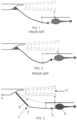
- FIGs 1 and 2 show a prior art refuelling system connected to a helicopter.
- the refuelling system for aircraft comprises a hose with a coupling.
- the hose connects the aircraft tanker to the receiver aircraft (which is a helicopter in Figures 1 and 2 ).
- the coupling is placed at the end of the hose and can be connected to a fuel inlet of the receiver aircraft.
- Typical length and weight of empty hoses are 30 m and 75 kg. When the hose is deployed it adopts a shape that is given by the equilibrium of the forces involved.
- the invention consists of introducing by some means additional forces onto the hose 2 to modify its shape in flight to keep the receiver 5 further away from the wake 11 of the tanker aircraft 4 and/or increase the distance between the hose 2 and the rotor from the beginning of the operation in the case of helicopters as receivers 5, what also reduces or even eliminates the need of the helicopter to fly higher in order to keep the hose 2 away from the rotor.
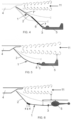
- Fig. 3 and Fig. 4 show an embodiment of the refuelling system 1 for aircraft of the invention where the distribution of weight along the hose 2 is used as an additional design parameter that allows modifying the shape of the hose 2 in flight to keep the coupling further away from the wake 11 of the tanker aircraft 4 and, in the case of helicopter as receivers 5, increase the distance between the hose 2 and the rotor from the beginning of the operation.
- the hose 2 consists of two stretches or sections 7, 7'; however, the hose 2 may consist of more than two stretches or sections (for instance, a third stretch or section can exist between stretch 7 and stretch 7').
- the stretch 7' closer to the tanker 4 is heavier than the one closer to the receiver 5.
- the weight of the first stretch 7' makes the hose 2 fly lower.
- the second stretch 7 is lighter to allow it to fly more horizontally and keep it further away from the rotor.
- the length of each stretch 7, 7' can be modified depending on the desired shape. In Fig.4 the heavier stretch is the second one, i.e. stretch 7. This lowers the coupling more effectively but increases hose angle thus reducing the distance hose-rotor, making this embodiment probably not appropriate for helicopters.
- Additional weights 6 can also be placed along intermediate sections placed between section 7 and section 7', or internally in those intermediate sections.
- the increase of weight along desired hose stretches 7, 7' could be achieved for example by manufacturing the hose 2 with different materials or by embedding lead (or other heavy material) thread in the material of conventional hoses. Given the lead density only 4.4 dm 3 of lead would increase the weight of the hose in 50 kg (the volume of a 30 m hose is around 235 dm 3 ).
- Fig. 5 shows another embodiment of the invention, in which a weight 8 close to the coupling 3 is placed. This weight 8 contributes to separating the receiver 5 from the wake 11 of the tanker aircraft 4 more efficiently than the previous embodiments.
- Fig. 6 shows another embodiment of the invention, in which at least one weight 8 is located in an intermediate position along hose length. These weights 8 contribute to separating the receiver 5 from the wake 11 of the tanker aircraft 4 less efficiently than the previous embodiment, but here the additional weights are placed far from the receiver 5 probe, what can reduce the loads on this probe during connection.
- Fig. 7 shows another embodiment of the invention, in which once the hose 2 is extended an additional weight 8 moves along the hose 2 to reach an appropriate position.
- This additional weight 8 can be deployed along the hose 2 by the action of the aerodynamic drag, and retracted for example with a hoist system 9.
- the at least one concentrated weight 8 can also be moved along the hose 2 through the action of a mechanical system with wheels or tracks that embrace the hose 2.
- An active brake can be incorporated to act on the additional weight 8 that moves along the hose 2 in order to avoid its movement once it has been placed in the desired position.
- Fig. 8 shows another embodiment of the invention, in which the means to introduce forces in the hose 2 consists of modifying aerodynamic drag by using hose diameter as an additional design parameter.
- the hose 2 consists of two stretches 7, 7' but they could be more than two. The first one has lower diameter to reduce drag and keep the coupling far from the tanker wake 11. The second one has bigger diameter to increase drag and fly more horizontal to keep it farther from a helicopter rotor. The increase of diameter could be achieved by surrounding the hose 2 with additional material 12, for instance.
- Fig. 9 shows another embodiment of the invention, in which the means to introduce forces in the hose 2 consists of aerodynamic devices 10 placed fixed or movable along the hose 2.
- the aerodynamic device 10 is able to produce a constant force downwards on the hose, or to produce a constant force downwards on the hose in addition to a torque to compensate hose rotation.
- the aerodynamic device 10 is not coupled with the hose rotation to avoid the need to compensate its rotation.
- the means proposed to place it in the right position can be the same proposed for weights in Fig. 7 .
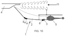
- Fig. 10 shows another embodiment of the invention, in which two of the previous embodiments are combined (the ones in figures 5 and 6 ).
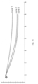
- Figure 11 shows several simulated hose shapes corresponding to several embodiments of refuelling systems 1 for aircraft of the invention.
- Curve 1 represents the hose shape of the refuelling system 1 when there is not any additional force on the hose 2 (prior art).
- Curve 2 represents the hose shape of the refuelling system 1 when there is a concentrated weight 8 of 50 kg in an intermediate position.
- Curve 3 represents the hose shape of the refuelling system 1 when there is a tripled hose weight per unit of length in the first 15 meters (i.e., an increased weight in a section of the hose 2).
Landscapes
- Engineering & Computer Science (AREA)
- Aviation & Aerospace Engineering (AREA)
- Rigid Pipes And Flexible Pipes (AREA)
Abstract
Description
- This invention refers to aerial refuelling systems, with special application in the refuelling of helicopters and airplanes from a tanker aircraft.
- When aircraft are refuelled inflight with hose-drogue refuelling systems, some receiver models can get very close to the wake of the tanker aircraft, what can cause several problems in the receiver, such as instability, control difficulties, vibrations, impossibility to reach the drogue... that make difficult or even impossible the refuelling operation. This is particularly important when refuelling helicopters or large aircraft receivers. In helicopters it is required to keep the hose of the refuelling system as far as possible from the helicopter rotor to avoid impact. In helicopters, immediately before contact takes place, the hose and the rotor are close to each other (see
Figure 1 ). Immediatly after connection the helicopter flies higher, thus increasing the distance between the hose and the rotor, but reducing the distance to the wake of the tanker aircraft (seeFigure 2 ). - The procedure described before has two main problems:
- The contact has to be conducted in a position in which the rotor and the hose are close to each other.
- When the helicopter flies higher it gets closer to the wake of the tanker aircraft.
- The same happens with the vertical tail of large aircraft receivers.
- One possible solution for this is to use a longer hose that flies lower under the wake of the tanker aircraft. However, the longer hose needs to have a lower diameter and therefore the maximum fuel flow is reduced. Alternatively, the hose storage system size could be increased but this would have other drawbacks, for example higher aerodynamic drag.
- The object of the present invention is to provide a refuelling system for aircraft that overcomes or mitigates the mentioned drawbacks without reducing the diameter (and maximum fuel flow) of the existing hoses or increasing the hose storage system size.
- The invention provides a refuelling system for aircraft, comprising a hose with a coupling, such that the hose is suitable for connecting an aircraft tanker to a receiver aircraft and the coupling is placed at one end of the hose and is suitable for connecting to a fuel inlet of the receiver aircraft, that additionally comprises means for introducing forces onto the hose in addition to the weight of the hose.
- The means to introduce additional forces along the hose is used to modify the shape of the hose in flight, in order to keep the receiver further away from the wake of the tanker aircraft and/or increase the distance between the hose and the rotor from the beginning of the operation in the case of helicopters as receivers.
- Accordingly, this configuration of the refuelling system modifying the distribution of weight along the length of the hose allows a change in the shape of the hose in flight, such that the mentioned problems of the prior art systems are avoided.
- Other characteristics and advantages of the present invention will be clear from the following detailed description of several embodiments illustrative of its object in relation to the attached figures.
-
-
Figure 1 shows a view of a prior art refuelling system connected to a tanker aircraft and to a helicopter immediately before the contact of the hose of the refuelling system with the helicopter. -
Figure 2 shows a view of a prior art refuelling system connected to a tanker aircraft and to a helicopter immediately after the contact of the hose of the refuelling system with the helicopter. -
Figure 3 shows a view of an embodiment of a refuelling system of the invention connected to a helicopter. -
Figure 4 shows a view of another embodiment of a refuelling system of the invention connected to an aeroplane. -
Figure 5 shows a view of another embodiment of a refuelling system of the invention connected to an aeroplane. -
Figure 6 shows a view of another embodiment of a refuelling system of the invention connected to a helicopter. -
Figure 7 shows a view of another embodiment of a refuelling system of the invention connected to a helicopter. -
Figure 8 shows a view of another embodiment of a refuelling system of the invention connected to a helicopter. -
Figure 9 shows a view of another embodiment of a refuelling system of the invention connected to a helicopter. -
Figure 10 shows a view of another embodiment of a refuelling system of the invention connected to a helicopter. -
Figure 11 shows several simulated hose shapes corresponding to several embodiments of refuelling systems for aircraft of the invention. -
Figures 1 and 2 show a prior art refuelling system connected to a helicopter. The refuelling system for aircraft comprises a hose with a coupling. The hose connects the aircraft tanker to the receiver aircraft (which is a helicopter inFigures 1 and 2 ). The coupling is placed at the end of the hose and can be connected to a fuel inlet of the receiver aircraft. Typical length and weight of empty hoses are 30 m and 75 kg. When the hose is deployed it adopts a shape that is given by the equilibrium of the forces involved. - The invention consists of introducing by some means additional forces onto the
hose 2 to modify its shape in flight to keep thereceiver 5 further away from thewake 11 of thetanker aircraft 4 and/or increase the distance between thehose 2 and the rotor from the beginning of the operation in the case of helicopters asreceivers 5, what also reduces or even eliminates the need of the helicopter to fly higher in order to keep thehose 2 away from the rotor. - In
Figure 1 it can be seen that in prior art refuelling systems immediately before the connection with the helicopter the hose of the refuelling system and the rotor of the helicopter are close to each other. InFigure 2 it can be seen that immediately after the contact of the hose with the helicopter, the helicopter flies higher, thus increasing the distance between the hose and the rotor but reducing the distance to the wake of the tanker aircraft. -
Fig. 3 andFig. 4 show an embodiment of therefuelling system 1 for aircraft of the invention where the distribution of weight along thehose 2 is used as an additional design parameter that allows modifying the shape of thehose 2 in flight to keep the coupling further away from thewake 11 of thetanker aircraft 4 and, in the case of helicopter asreceivers 5, increase the distance between thehose 2 and the rotor from the beginning of the operation. InFig. 3 thehose 2 consists of two stretches orsections 7, 7'; however, thehose 2 may consist of more than two stretches or sections (for instance, a third stretch or section can exist betweenstretch 7 and stretch 7'). The stretch 7' closer to thetanker 4 is heavier than the one closer to thereceiver 5. The weight of the first stretch 7' makes thehose 2 fly lower. Thesecond stretch 7 is lighter to allow it to fly more horizontally and keep it further away from the rotor. The length of eachstretch 7, 7' can be modified depending on the desired shape. InFig.4 the heavier stretch is the second one, i.e.stretch 7. This lowers the coupling more effectively but increases hose angle thus reducing the distance hose-rotor, making this embodiment probably not appropriate for helicopters. - In
Fig. 3 additional weights 6 are placed externally on section 7' of thehose 2. It is also possible thatadditional weights 6 are placed internally in section 7'. - In
Fig. 4 additional weights 6 are placed externally onsection 7 of thehose 2. It is also possible thatadditional weights 6 are placed internally insection 7. - In
Fig. 4 theadditional weights 6 are placed along thesection 7 of thehose 2 that comprises thecoupling 3. - In
Fig. 3 theadditional weights 6 are placed along the section 7' of thehose 2 opposite thesection 7 of thehose 2 that comprises thecoupling 3. -
Additional weights 6 can also be placed along intermediate sections placed betweensection 7 and section 7', or internally in those intermediate sections. - The increase of weight along desired hose stretches 7, 7' could be achieved for example by manufacturing the
hose 2 with different materials or by embedding lead (or other heavy material) thread in the material of conventional hoses. Given the lead density only 4.4 dm3 of lead would increase the weight of the hose in 50 kg (the volume of a 30 m hose is around 235 dm3). -
Fig. 5 shows another embodiment of the invention, in which aweight 8 close to thecoupling 3 is placed. Thisweight 8 contributes to separating thereceiver 5 from thewake 11 of thetanker aircraft 4 more efficiently than the previous embodiments. -
Fig. 6 shows another embodiment of the invention, in which at least oneweight 8 is located in an intermediate position along hose length. Theseweights 8 contribute to separating thereceiver 5 from thewake 11 of thetanker aircraft 4 less efficiently than the previous embodiment, but here the additional weights are placed far from thereceiver 5 probe, what can reduce the loads on this probe during connection. -
Fig. 7 shows another embodiment of the invention, in which once thehose 2 is extended anadditional weight 8 moves along thehose 2 to reach an appropriate position. Thisadditional weight 8 can be deployed along thehose 2 by the action of the aerodynamic drag, and retracted for example with a hoist system 9. The at least oneconcentrated weight 8 can also be moved along thehose 2 through the action of a mechanical system with wheels or tracks that embrace thehose 2. An active brake can be incorporated to act on theadditional weight 8 that moves along thehose 2 in order to avoid its movement once it has been placed in the desired position. -
Fig. 8 shows another embodiment of the invention, in which the means to introduce forces in thehose 2 consists of modifying aerodynamic drag by using hose diameter as an additional design parameter. In this figure thehose 2 consists of twostretches 7, 7' but they could be more than two. The first one has lower diameter to reduce drag and keep the coupling far from thetanker wake 11. The second one has bigger diameter to increase drag and fly more horizontal to keep it farther from a helicopter rotor. The increase of diameter could be achieved by surrounding thehose 2 withadditional material 12, for instance. -
Fig. 9 shows another embodiment of the invention, in which the means to introduce forces in thehose 2 consists ofaerodynamic devices 10 placed fixed or movable along thehose 2. Theaerodynamic device 10 is able to produce a constant force downwards on the hose, or to produce a constant force downwards on the hose in addition to a torque to compensate hose rotation. In another option, theaerodynamic device 10 is not coupled with the hose rotation to avoid the need to compensate its rotation. In case of movable device, the means proposed to place it in the right position can be the same proposed for weights inFig. 7 . -
Fig. 10 shows another embodiment of the invention, in which two of the previous embodiments are combined (the ones infigures 5 and 6 ). -
Figure 11 shows several simulated hose shapes corresponding to several embodiments ofrefuelling systems 1 for aircraft of the invention.Curve 1 represents the hose shape of therefuelling system 1 when there is not any additional force on the hose 2 (prior art).Curve 2 represents the hose shape of therefuelling system 1 when there is aconcentrated weight 8 of 50 kg in an intermediate position.Curve 3 represents the hose shape of therefuelling system 1 when there is a tripled hose weight per unit of length in the first 15 meters (i.e., an increased weight in a section of the hose 2). - Although the present invention has been fully described in connection with suggested embodiments, it is evident that modifications may be introduced within the scope thereof, not considering this as limited by these embodiments, but by the contents of the following claims.
Claims (15)
- Refuelling system (1) for aircraft, comprising a hose (2) with a coupling (3), such that the hose (2) is suitable for connecting an aircraft tanker (4) to a receiver aircraft (5) and the coupling (3) is placed at one end of the hose (2) and is suitable for connecting to a fuel inlet of the receiver aircraft (5), characterized in that it additionally comprises means for introducing forces onto the hose (2) in addition to the weight of the hose (2).
- Refuelling system (1) for aircraft, according to claim 1, wherein the hose (2) comprises at least two sections (7, 7') and the means for introducing forces onto the hose (2) in addition to the weight of the hose (2) are additional weights (6) along at least one section (7, 7') of the hose (2).
- Refuelling system (1) for aircraft, according to claim 2, wherein the means for introducing forces onto the hose (2) in addition to the weight of the hose (2) are:- additional weights (6) placed internally in at least one section (7, 7') of the hose (2) or- additional weights (6) placed externally on at least one section (7, 7') of the hose (2).
- Refuelling system (1) for aircraft, according to any of claims 2 or 3, wherein the additional weights (6) are placed:- along the section (7) of the hose (2) that comprises the coupling (3) or- along the section (7') of the hose (2) opposite the section (7) of the hose (2) that comprises the coupling (3).
- Refuelling system (1) for aircraft, according to claim 1, wherein the means for introducing forces onto the hose (2) in addition to the weight of the hose (2) is at least one concentrated weight (8).
- Refuelling system (1) for aircraft, according to claim 5, wherein the at least one concentrated weight (8) is placed close to the coupling (3).
- Refuelling system (1) for aircraft, according to claim 5, wherein the at least one concentrated weight (8) is placed in an intermediate position on the hose (2).
- Refuelling system (1) for aircraft, according to claim 5, wherein the at least one concentrated weight (8) can be placed at any position on the hose (2).
- Refuelling system (1) for aircraft, according to claim 8, wherein the at least one concentrated weight (8) can move along the hose (2) through the action of a hoist system (9).
- Refuelling system (1) for aircraft, according to claim 8, wherein the at least one concentrated weight (8) can move along the hose (2) through the action of a mechanical system with wheels or tracks that embrace the hose (2).
- Refuelling system (1) for aircraft, according to claim 9 or 10, which additionally comprises an active brake to act on the at least one concentrated weight (8) to block its movement along the hose (2) once the concentrated weight (8) is properly placed.
- Refuelling system (1) for aircraft, according to claim 1, wherein the means for introducing forces onto the hose (2) in addition to the weight of the hose (2) is at least one aerodynamic device (10) placed on the hose (2).
- Refuelling system (1) for aircraft, according to claim 12, wherein the at least one aerodynamic device (10) is fixed or movable on the hose (2).
- Refuelling system (1) for aircraft, according to claim 1, wherein the means for introducing forces onto the hose (2) in addition to the weight of the hose (2) is at least one additional material (12) on at least one section (7, 7') of the hose (2), thus increasing the external diameter of the hose (2).
- Refuelling system (1) for aircraft, according to claim 2, that additionally comprises at least one concentrated weight (8) and/or at least one aerodynamic device (10) placed on the hose (2) and/or at least one additional material (12) on at least one section (7, 7') of the hose (2), thus increasing the external diameter of the hose (2).
Priority Applications (2)
| Application Number | Priority Date | Filing Date | Title |
|---|---|---|---|
| ES22383220T ES3041475T3 (en) | 2022-12-15 | 2022-12-15 | Refuelling system for aircraft |
| EP22383220.5A EP4385901B1 (en) | 2022-12-15 | 2022-12-15 | Refuelling system for aircraft |
Applications Claiming Priority (1)
| Application Number | Priority Date | Filing Date | Title |
|---|---|---|---|
| EP22383220.5A EP4385901B1 (en) | 2022-12-15 | 2022-12-15 | Refuelling system for aircraft |
Publications (2)
| Publication Number | Publication Date |
|---|---|
| EP4385901A1 true EP4385901A1 (en) | 2024-06-19 |
| EP4385901B1 EP4385901B1 (en) | 2025-07-23 |
Family
ID=85556640
Family Applications (1)
| Application Number | Title | Priority Date | Filing Date |
|---|---|---|---|
| EP22383220.5A Active EP4385901B1 (en) | 2022-12-15 | 2022-12-15 | Refuelling system for aircraft |
Country Status (2)
| Country | Link |
|---|---|
| EP (1) | EP4385901B1 (en) |
| ES (1) | ES3041475T3 (en) |
Citations (7)
| Publication number | Priority date | Publication date | Assignee | Title |
|---|---|---|---|---|
| US2879017A (en) * | 1955-01-25 | 1959-03-24 | Flight Refueling Inc | Apparatus for interconnecting aircraft in flight |
| US20060043241A1 (en) * | 2004-08-24 | 2006-03-02 | The Boeing Company | In-flight refueling system, bladder device and method for preventing oscillations in in-flight refueling system components |
| US20060060710A1 (en) * | 2004-09-21 | 2006-03-23 | The Boeing Company | In-flight refueling system, damping device and method for preventing oscillations in in-flight refueling system components |
| US20150041591A1 (en) * | 2013-08-06 | 2015-02-12 | The Boeing Company | Multipurpose flying boom |
| US20200239154A1 (en) * | 2019-01-24 | 2020-07-30 | Airbus Helicopters Deutschland GmbH | En route fluid transmitting apparatus |
| US20210300585A1 (en) * | 2020-03-30 | 2021-09-30 | Cobham Mission Systems Wimborne Limited | Air-to-air refuelling drogue assembly |
| EP3842345B1 (en) * | 2020-10-29 | 2022-10-19 | Airbus Defence and Space, S.A.U. | Air to air active refuelling system and method for generating aerodynamic radial loads at a hose-end |
-
2022
- 2022-12-15 EP EP22383220.5A patent/EP4385901B1/en active Active
- 2022-12-15 ES ES22383220T patent/ES3041475T3/en active Active
Patent Citations (7)
| Publication number | Priority date | Publication date | Assignee | Title |
|---|---|---|---|---|
| US2879017A (en) * | 1955-01-25 | 1959-03-24 | Flight Refueling Inc | Apparatus for interconnecting aircraft in flight |
| US20060043241A1 (en) * | 2004-08-24 | 2006-03-02 | The Boeing Company | In-flight refueling system, bladder device and method for preventing oscillations in in-flight refueling system components |
| US20060060710A1 (en) * | 2004-09-21 | 2006-03-23 | The Boeing Company | In-flight refueling system, damping device and method for preventing oscillations in in-flight refueling system components |
| US20150041591A1 (en) * | 2013-08-06 | 2015-02-12 | The Boeing Company | Multipurpose flying boom |
| US20200239154A1 (en) * | 2019-01-24 | 2020-07-30 | Airbus Helicopters Deutschland GmbH | En route fluid transmitting apparatus |
| US20210300585A1 (en) * | 2020-03-30 | 2021-09-30 | Cobham Mission Systems Wimborne Limited | Air-to-air refuelling drogue assembly |
| EP3842345B1 (en) * | 2020-10-29 | 2022-10-19 | Airbus Defence and Space, S.A.U. | Air to air active refuelling system and method for generating aerodynamic radial loads at a hose-end |
Also Published As
| Publication number | Publication date |
|---|---|
| ES3041475T3 (en) | 2025-11-12 |
| EP4385901B1 (en) | 2025-07-23 |
Similar Documents
| Publication | Publication Date | Title |
|---|---|---|
| US12384559B2 (en) | Rotorcraft-assisted system and method for launching and retrieving a fixed-wing aircraft into and from free flight | |
| US6783096B2 (en) | Vertical lift flying craft | |
| RU2235045C1 (en) | Flying vehicle | |
| US8028952B2 (en) | System for shipboard launch and recovery of unmanned aerial vehicle (UAV) aircraft and method therefor | |
| US7850121B2 (en) | Enhanced ruddevator for improved air refueling boom flight control | |
| US20130299634A1 (en) | Aerodynamically controlled grapple assembly | |
| US20160221689A1 (en) | Line Intersect Vehicle Launch and Recovery | |
| WO2002055385A1 (en) | A drogue for in-flight refuelling | |
| US3679157A (en) | Aircrew recovery system | |
| US20200039632A1 (en) | Wind Energy Kite Tail | |
| KR102227640B1 (en) | Rotary-wing Aircraft Automatic Landing System | |
| CA2879296C (en) | Wing aerial refueling system | |
| US3249322A (en) | Air train | |
| EP4385901B1 (en) | Refuelling system for aircraft | |
| US8485469B2 (en) | Aerodynamically controlled grapple assembly | |
| US3113751A (en) | Aerial cargo delivery system | |
| RU2104903C1 (en) | Helicopter-aerostat complex | |
| CN111174646A (en) | Rocket fairing recovery system and method | |
| US12415633B2 (en) | Multistage suspension for UAV landing gear | |
| GB2600422A (en) | Recovery aircraft and method | |
| CN112373706B (en) | A soft air refueling variable damping stabilization parachute | |
| EP4153489A1 (en) | Device for refueling air vehicles | |
| US2936977A (en) | Means for arresting aircraft | |
| RU2790300C1 (en) | External helicopter suspension for large-size cargo (options) | |
| CN215554148U (en) | Unmanned aerial vehicle rope throwing device |
Legal Events
| Date | Code | Title | Description |
|---|---|---|---|
| PUAI | Public reference made under article 153(3) epc to a published international application that has entered the european phase |
Free format text: ORIGINAL CODE: 0009012 |
|
| STAA | Information on the status of an ep patent application or granted ep patent |
Free format text: STATUS: THE APPLICATION HAS BEEN PUBLISHED |
|
| AK | Designated contracting states |
Kind code of ref document: A1 Designated state(s): AL AT BE BG CH CY CZ DE DK EE ES FI FR GB GR HR HU IE IS IT LI LT LU LV MC ME MK MT NL NO PL PT RO RS SE SI SK SM TR |
|
| STAA | Information on the status of an ep patent application or granted ep patent |
Free format text: STATUS: REQUEST FOR EXAMINATION WAS MADE |
|
| 17P | Request for examination filed |
Effective date: 20241218 |
|
| GRAP | Despatch of communication of intention to grant a patent |
Free format text: ORIGINAL CODE: EPIDOSNIGR1 |
|
| STAA | Information on the status of an ep patent application or granted ep patent |
Free format text: STATUS: GRANT OF PATENT IS INTENDED |
|
| INTG | Intention to grant announced |
Effective date: 20250403 |
|
| GRAS | Grant fee paid |
Free format text: ORIGINAL CODE: EPIDOSNIGR3 |
|
| GRAA | (expected) grant |
Free format text: ORIGINAL CODE: 0009210 |
|
| STAA | Information on the status of an ep patent application or granted ep patent |
Free format text: STATUS: THE PATENT HAS BEEN GRANTED |
|
| AK | Designated contracting states |
Kind code of ref document: B1 Designated state(s): AL AT BE BG CH CY CZ DE DK EE ES FI FR GB GR HR HU IE IS IT LI LT LU LV MC ME MK MT NL NO PL PT RO RS SE SI SK SM TR |
|
| REG | Reference to a national code |
Ref country code: GB Ref legal event code: FG4D |
|
| REG | Reference to a national code |
Ref country code: CH Ref legal event code: EP |
|
| REG | Reference to a national code |
Ref country code: IE Ref legal event code: FG4D |
|
| REG | Reference to a national code |
Ref country code: DE Ref legal event code: R096 Ref document number: 602022018030 Country of ref document: DE |
|
| REG | Reference to a national code |
Ref country code: ES Ref legal event code: FG2A Ref document number: 3041475 Country of ref document: ES Kind code of ref document: T3 Effective date: 20251112 |
|
| REG | Reference to a national code |
Ref country code: NL Ref legal event code: MP Effective date: 20250723 |
|
| PG25 | Lapsed in a contracting state [announced via postgrant information from national office to epo] |
Ref country code: PT Free format text: LAPSE BECAUSE OF FAILURE TO SUBMIT A TRANSLATION OF THE DESCRIPTION OR TO PAY THE FEE WITHIN THE PRESCRIBED TIME-LIMIT Effective date: 20251124 |
|
| PG25 | Lapsed in a contracting state [announced via postgrant information from national office to epo] |
Ref country code: NL Free format text: LAPSE BECAUSE OF FAILURE TO SUBMIT A TRANSLATION OF THE DESCRIPTION OR TO PAY THE FEE WITHIN THE PRESCRIBED TIME-LIMIT Effective date: 20250723 |
|
| REG | Reference to a national code |
Ref country code: AT Ref legal event code: MK05 Ref document number: 1816209 Country of ref document: AT Kind code of ref document: T Effective date: 20250723 |
|
| PG25 | Lapsed in a contracting state [announced via postgrant information from national office to epo] |
Ref country code: IS Free format text: LAPSE BECAUSE OF FAILURE TO SUBMIT A TRANSLATION OF THE DESCRIPTION OR TO PAY THE FEE WITHIN THE PRESCRIBED TIME-LIMIT Effective date: 20251123 |
|
| PGFP | Annual fee paid to national office [announced via postgrant information from national office to epo] |
Ref country code: DE Payment date: 20251211 Year of fee payment: 4 |
|
| PG25 | Lapsed in a contracting state [announced via postgrant information from national office to epo] |
Ref country code: NO Free format text: LAPSE BECAUSE OF FAILURE TO SUBMIT A TRANSLATION OF THE DESCRIPTION OR TO PAY THE FEE WITHIN THE PRESCRIBED TIME-LIMIT Effective date: 20251023 |
|
| REG | Reference to a national code |
Ref country code: LT Ref legal event code: MG9D |
|
| PG25 | Lapsed in a contracting state [announced via postgrant information from national office to epo] |
Ref country code: AT Free format text: LAPSE BECAUSE OF FAILURE TO SUBMIT A TRANSLATION OF THE DESCRIPTION OR TO PAY THE FEE WITHIN THE PRESCRIBED TIME-LIMIT Effective date: 20250723 |
|
| PG25 | Lapsed in a contracting state [announced via postgrant information from national office to epo] |
Ref country code: FI Free format text: LAPSE BECAUSE OF FAILURE TO SUBMIT A TRANSLATION OF THE DESCRIPTION OR TO PAY THE FEE WITHIN THE PRESCRIBED TIME-LIMIT Effective date: 20250723 |
|
| PG25 | Lapsed in a contracting state [announced via postgrant information from national office to epo] |
Ref country code: HR Free format text: LAPSE BECAUSE OF FAILURE TO SUBMIT A TRANSLATION OF THE DESCRIPTION OR TO PAY THE FEE WITHIN THE PRESCRIBED TIME-LIMIT Effective date: 20250723 |
|
| PGFP | Annual fee paid to national office [announced via postgrant information from national office to epo] |
Ref country code: FR Payment date: 20251229 Year of fee payment: 4 |
|
| PG25 | Lapsed in a contracting state [announced via postgrant information from national office to epo] |
Ref country code: GR Free format text: LAPSE BECAUSE OF FAILURE TO SUBMIT A TRANSLATION OF THE DESCRIPTION OR TO PAY THE FEE WITHIN THE PRESCRIBED TIME-LIMIT Effective date: 20251024 |
|
| PG25 | Lapsed in a contracting state [announced via postgrant information from national office to epo] |
Ref country code: SE Free format text: LAPSE BECAUSE OF FAILURE TO SUBMIT A TRANSLATION OF THE DESCRIPTION OR TO PAY THE FEE WITHIN THE PRESCRIBED TIME-LIMIT Effective date: 20250723 |
|
| PG25 | Lapsed in a contracting state [announced via postgrant information from national office to epo] |
Ref country code: LV Free format text: LAPSE BECAUSE OF FAILURE TO SUBMIT A TRANSLATION OF THE DESCRIPTION OR TO PAY THE FEE WITHIN THE PRESCRIBED TIME-LIMIT Effective date: 20250723 |
|
| PG25 | Lapsed in a contracting state [announced via postgrant information from national office to epo] |
Ref country code: PL Free format text: LAPSE BECAUSE OF FAILURE TO SUBMIT A TRANSLATION OF THE DESCRIPTION OR TO PAY THE FEE WITHIN THE PRESCRIBED TIME-LIMIT Effective date: 20250723 Ref country code: BG Free format text: LAPSE BECAUSE OF FAILURE TO SUBMIT A TRANSLATION OF THE DESCRIPTION OR TO PAY THE FEE WITHIN THE PRESCRIBED TIME-LIMIT Effective date: 20250723 |
|
| PG25 | Lapsed in a contracting state [announced via postgrant information from national office to epo] |
Ref country code: RS Free format text: LAPSE BECAUSE OF FAILURE TO SUBMIT A TRANSLATION OF THE DESCRIPTION OR TO PAY THE FEE WITHIN THE PRESCRIBED TIME-LIMIT Effective date: 20251023 |
|
| PG25 | Lapsed in a contracting state [announced via postgrant information from national office to epo] |
Ref country code: RO Free format text: LAPSE BECAUSE OF FAILURE TO SUBMIT A TRANSLATION OF THE DESCRIPTION OR TO PAY THE FEE WITHIN THE PRESCRIBED TIME-LIMIT Effective date: 20250723 |
|
| PG25 | Lapsed in a contracting state [announced via postgrant information from national office to epo] |
Ref country code: SM Free format text: LAPSE BECAUSE OF FAILURE TO SUBMIT A TRANSLATION OF THE DESCRIPTION OR TO PAY THE FEE WITHIN THE PRESCRIBED TIME-LIMIT Effective date: 20250723 |
|
| PGFP | Annual fee paid to national office [announced via postgrant information from national office to epo] |
Ref country code: ES Payment date: 20260130 Year of fee payment: 4 |
|
| PG25 | Lapsed in a contracting state [announced via postgrant information from national office to epo] |
Ref country code: DK Free format text: LAPSE BECAUSE OF FAILURE TO SUBMIT A TRANSLATION OF THE DESCRIPTION OR TO PAY THE FEE WITHIN THE PRESCRIBED TIME-LIMIT Effective date: 20250723 |
|
| PG25 | Lapsed in a contracting state [announced via postgrant information from national office to epo] |
Ref country code: IT Free format text: LAPSE BECAUSE OF FAILURE TO SUBMIT A TRANSLATION OF THE DESCRIPTION OR TO PAY THE FEE WITHIN THE PRESCRIBED TIME-LIMIT Effective date: 20250723 |
|
| PG25 | Lapsed in a contracting state [announced via postgrant information from national office to epo] |
Ref country code: CZ Free format text: LAPSE BECAUSE OF FAILURE TO SUBMIT A TRANSLATION OF THE DESCRIPTION OR TO PAY THE FEE WITHIN THE PRESCRIBED TIME-LIMIT Effective date: 20250723 |
|
| PG25 | Lapsed in a contracting state [announced via postgrant information from national office to epo] |
Ref country code: SK Free format text: LAPSE BECAUSE OF FAILURE TO SUBMIT A TRANSLATION OF THE DESCRIPTION OR TO PAY THE FEE WITHIN THE PRESCRIBED TIME-LIMIT Effective date: 20250723 Ref country code: EE Free format text: LAPSE BECAUSE OF FAILURE TO SUBMIT A TRANSLATION OF THE DESCRIPTION OR TO PAY THE FEE WITHIN THE PRESCRIBED TIME-LIMIT Effective date: 20250723 |