EP4385859A1 - Lower vehicle body front structure and vehicle - Google Patents
Lower vehicle body front structure and vehicle Download PDFInfo
- Publication number
- EP4385859A1 EP4385859A1 EP22855107.3A EP22855107A EP4385859A1 EP 4385859 A1 EP4385859 A1 EP 4385859A1 EP 22855107 A EP22855107 A EP 22855107A EP 4385859 A1 EP4385859 A1 EP 4385859A1
- Authority
- EP
- European Patent Office
- Prior art keywords
- engine room
- longitudinal
- energy absorption
- transverse beam
- upper transverse
- Prior art date
- Legal status (The legal status is an assumption and is not a legal conclusion. Google has not performed a legal analysis and makes no representation as to the accuracy of the status listed.)
- Pending
Links
- 238000010521 absorption reaction Methods 0.000 claims abstract description 142
- 239000006096 absorbing agent Substances 0.000 claims abstract description 37
- 230000035939 shock Effects 0.000 claims abstract description 37
- 230000003014 reinforcing effect Effects 0.000 claims description 29
- 230000002787 reinforcement Effects 0.000 claims description 19
- 229910000838 Al alloy Inorganic materials 0.000 claims description 8
- 229910052782 aluminium Inorganic materials 0.000 claims description 7
- XAGFODPZIPBFFR-UHFFFAOYSA-N aluminium Chemical compound [Al] XAGFODPZIPBFFR-UHFFFAOYSA-N 0.000 claims description 7
- 230000000712 assembly Effects 0.000 claims description 7
- 238000000429 assembly Methods 0.000 claims description 7
- 230000000630 rising effect Effects 0.000 claims description 3
- 239000000306 component Substances 0.000 description 20
- 230000003139 buffering effect Effects 0.000 description 16
- 238000010586 diagram Methods 0.000 description 13
- 230000009286 beneficial effect Effects 0.000 description 11
- 230000000694 effects Effects 0.000 description 10
- 238000013461 design Methods 0.000 description 8
- 238000000034 method Methods 0.000 description 8
- 238000010276 construction Methods 0.000 description 7
- 230000008569 process Effects 0.000 description 6
- 229910000831 Steel Inorganic materials 0.000 description 5
- 230000006378 damage Effects 0.000 description 5
- 239000010959 steel Substances 0.000 description 5
- 230000002829 reductive effect Effects 0.000 description 4
- 238000012423 maintenance Methods 0.000 description 3
- 230000008093 supporting effect Effects 0.000 description 3
- 238000003466 welding Methods 0.000 description 3
- 230000005540 biological transmission Effects 0.000 description 2
- 238000005266 casting Methods 0.000 description 2
- 230000006872 improvement Effects 0.000 description 2
- 239000000463 material Substances 0.000 description 2
- 238000000465 moulding Methods 0.000 description 2
- 238000012545 processing Methods 0.000 description 2
- 230000001681 protective effect Effects 0.000 description 2
- 230000002411 adverse Effects 0.000 description 1
- 239000008358 core component Substances 0.000 description 1
- 230000008878 coupling Effects 0.000 description 1
- 238000010168 coupling process Methods 0.000 description 1
- 238000005859 coupling reaction Methods 0.000 description 1
- 238000004880 explosion Methods 0.000 description 1
- 238000001125 extrusion Methods 0.000 description 1
- 230000010354 integration Effects 0.000 description 1
- 238000004519 manufacturing process Methods 0.000 description 1
- 229910052751 metal Inorganic materials 0.000 description 1
- 239000002184 metal Substances 0.000 description 1
- 230000004048 modification Effects 0.000 description 1
- 238000012986 modification Methods 0.000 description 1
- 230000036961 partial effect Effects 0.000 description 1
- 238000006467 substitution reaction Methods 0.000 description 1
- 230000003313 weakening effect Effects 0.000 description 1
Images




Classifications
-
- B—PERFORMING OPERATIONS; TRANSPORTING
- B62—LAND VEHICLES FOR TRAVELLING OTHERWISE THAN ON RAILS
- B62D—MOTOR VEHICLES; TRAILERS
- B62D21/00—Understructures, i.e. chassis frame on which a vehicle body may be mounted
- B62D21/02—Understructures, i.e. chassis frame on which a vehicle body may be mounted comprising longitudinally or transversely arranged frame members
-
- B—PERFORMING OPERATIONS; TRANSPORTING
- B62—LAND VEHICLES FOR TRAVELLING OTHERWISE THAN ON RAILS
- B62D—MOTOR VEHICLES; TRAILERS
- B62D25/00—Superstructure or monocoque structure sub-units; Parts or details thereof not otherwise provided for
- B62D25/08—Front or rear portions
- B62D25/082—Engine compartments
-
- B—PERFORMING OPERATIONS; TRANSPORTING
- B60—VEHICLES IN GENERAL
- B60K—ARRANGEMENT OR MOUNTING OF PROPULSION UNITS OR OF TRANSMISSIONS IN VEHICLES; ARRANGEMENT OR MOUNTING OF PLURAL DIVERSE PRIME-MOVERS IN VEHICLES; AUXILIARY DRIVES FOR VEHICLES; INSTRUMENTATION OR DASHBOARDS FOR VEHICLES; ARRANGEMENTS IN CONNECTION WITH COOLING, AIR INTAKE, GAS EXHAUST OR FUEL SUPPLY OF PROPULSION UNITS IN VEHICLES
- B60K11/00—Arrangement in connection with cooling of propulsion units
-
- B—PERFORMING OPERATIONS; TRANSPORTING
- B60—VEHICLES IN GENERAL
- B60R—VEHICLES, VEHICLE FITTINGS, OR VEHICLE PARTS, NOT OTHERWISE PROVIDED FOR
- B60R19/00—Wheel guards; Radiator guards, e.g. grilles; Obstruction removers; Fittings damping bouncing force in collisions
- B60R19/02—Bumpers, i.e. impact receiving or absorbing members for protecting vehicles or fending off blows from other vehicles or objects
- B60R19/24—Arrangements for mounting bumpers on vehicles
- B60R19/26—Arrangements for mounting bumpers on vehicles comprising yieldable mounting means
- B60R19/34—Arrangements for mounting bumpers on vehicles comprising yieldable mounting means destroyed upon impact, e.g. one-shot type
-
- B—PERFORMING OPERATIONS; TRANSPORTING
- B62—LAND VEHICLES FOR TRAVELLING OTHERWISE THAN ON RAILS
- B62D—MOTOR VEHICLES; TRAILERS
- B62D21/00—Understructures, i.e. chassis frame on which a vehicle body may be mounted
- B62D21/11—Understructures, i.e. chassis frame on which a vehicle body may be mounted with resilient means for suspension, e.g. of wheels or engine; sub-frames for mounting engine or suspensions
-
- B—PERFORMING OPERATIONS; TRANSPORTING
- B62—LAND VEHICLES FOR TRAVELLING OTHERWISE THAN ON RAILS
- B62D—MOTOR VEHICLES; TRAILERS
- B62D21/00—Understructures, i.e. chassis frame on which a vehicle body may be mounted
- B62D21/15—Understructures, i.e. chassis frame on which a vehicle body may be mounted having impact absorbing means, e.g. a frame designed to permanently or temporarily change shape or dimension upon impact with another body
- B62D21/152—Front or rear frames
-
- B—PERFORMING OPERATIONS; TRANSPORTING
- B62—LAND VEHICLES FOR TRAVELLING OTHERWISE THAN ON RAILS
- B62D—MOTOR VEHICLES; TRAILERS
- B62D21/00—Understructures, i.e. chassis frame on which a vehicle body may be mounted
- B62D21/15—Understructures, i.e. chassis frame on which a vehicle body may be mounted having impact absorbing means, e.g. a frame designed to permanently or temporarily change shape or dimension upon impact with another body
- B62D21/157—Understructures, i.e. chassis frame on which a vehicle body may be mounted having impact absorbing means, e.g. a frame designed to permanently or temporarily change shape or dimension upon impact with another body for side impacts
-
- B—PERFORMING OPERATIONS; TRANSPORTING
- B62—LAND VEHICLES FOR TRAVELLING OTHERWISE THAN ON RAILS
- B62D—MOTOR VEHICLES; TRAILERS
- B62D29/00—Superstructures, understructures, or sub-units thereof, characterised by the material thereof
- B62D29/008—Superstructures, understructures, or sub-units thereof, characterised by the material thereof predominantly of light alloys, e.g. extruded
-
- B—PERFORMING OPERATIONS; TRANSPORTING
- B62—LAND VEHICLES FOR TRAVELLING OTHERWISE THAN ON RAILS
- B62D—MOTOR VEHICLES; TRAILERS
- B62D25/00—Superstructure or monocoque structure sub-units; Parts or details thereof not otherwise provided for
- B62D25/08—Front or rear portions
- B62D25/088—Details of structures as upper supports for springs or dampers
Definitions
- the present application relates to the technical field of body structures of vehicles, in particular to a lower vehicle-body front structure. Meanwhile, the present application also relates to a vehicle provided with the lower vehicle-body front structure.
- a front anti-collision beam mainly functions to receive collision from front of the vehicle, and the front anti-collision beam is generally connected to a front longitudinal beam of the engine room through structures such as an energy absorption box of the front anti-collision beam and a connecting bracket.
- An impact force received by the front anti-collision beam is transmitted to the front longitudinal beam of the engine room along a path from the front anti-collision beam, to the energy absorption box of the front anti-collision beam and to the connecting bracket.
- the front anti-collision beam and the energy absorption box of the front anti-collision beam are mainly provided to deal with the collision from the front of the vehicle and to function in buffering and absorbing energy, and to prevent an excessive impact force from being directly transmitted to the front longitudinal beam of the engine room, which may further transmit the impact force to a cockpit, or even the longitudinal beam of the engine room directly invades into the cockpit and causes adverse effect on personal safety of drivers and passengers.
- the front anti-collision beam and the front longitudinal beam of the engine room are disposed at relatively low positions.
- an impact force is easily transmitted directly to an interior of the front engine room, causing serious damage to core components such as an engine.
- an excessive impact force may also impact and move backwards components in the front engine room, and invade into the cockpit, causing harm to drivers and passengers.
- an existing connecting bracket for connecting the front anti-collision beam and the front longitudinal beam of the engine room is fixedly mounted at a front end of the front longitudinal beam of the engine room, which is generally simple in structure and mainly functions in connection and mounting, and may also contribute to mounting and connection of surrounding components such as a front subframe and a locking and mounting transverse beam of the engine room.
- the connecting bracket When the impact force from the front anti-collision beam reaches the connecting bracket, the impact force may be directly transferred to the front longitudinal beam of the engine room.
- the present application aims to propose a lower vehicle-body front structure to improve collision protection performance of a front body.
- the lower vehicle-body front structure includes front longitudinal beams of an engine room respectively arranged at two sides, a front anti-collision beam connected between front ends of the front longitudinal beams of the engine room at the two sides, and a rear transverse beam of the engine room connected between rear ends of the front longitudinal beams of the engine room at the two sides, the front longitudinal beams of the engine room at the two sides are respectively connected to front shock absorber seatseats;
- each end of the upper transverse beam of the front engine room is detachably connected to the side beam of the front wheel cover at a corresponding side; the energy absorption box of the upper transverse beam of the front engine room is detachably connected between the upper transverse beam of the front engine room and the front shock absorber seatseat; and/or, along a direction towards the rear of the vehicle body, both ends of the upper transverse beam of the front engine room connected to the side beams of the front wheel covers at the two sides are arranged in a gradually rising manner; the energy absorption box of the upper transverse beam of the front engine room is in a grid shape formed by interweaving and connecting a plurality of plate bodies.
- each of the connecting seatseats includes a structural main body; the energy absorption part is located at a lower part of a rear side of the structural main body, and a connecting part of the longitudinal beam of the engine room is provided at an inner side of the energy absorption part; the connecting part of the longitudinal beam of the engine room and the energy absorption part are respectively provided with longitudinal-beam connecting holes for connecting the longitudinal beam of the engine room; and a protruding height of the energy absorption part gradually increases along a direction to the front longitudinal beam of the engine room.
- the energy absorption part includes a longitudinal plate body fixedly connected to the structural main body and a transverse plate body fixedly connected between the structural main body and the longitudinal plate body
- the connecting part of the longitudinal beam of the engine room includes a connecting plate fixedly connected to the structural main body; a plurality of transverse plate bodies are arranged at intervals in an up-and-down direction, the connecting plate is connected to the longitudinal plate body, and a connecting cavity where an end of the longitudinal beam of the engine room is capable to be inserted is defined between the connecting plate and the longitudinal plate body; and the longitudinal plate body and the connecting plate are respectively provided with the longitudinal-beam connecting holes.
- a connecting bracket and a radiator mounting bracket are provided at a top of the structural main body; and the upper transverse beam of the front engine room is detachably connected to the connecting bracket on each of the connecting seatseats.
- the front longitudinal beam of the engine room includes a longitudinal beam body, and the longitudinal beam body is provided with a main body part and a reinforcing part;
- the main body part includes two main beam bodies which are integrally connected in an up-and-down direction, and an interior of each main beam body is hollow, so that the main body part is provided with two cavity structures arranged in the up-and-down direction;
- the reinforcement part includes a reinforcement beam body integrally and fixedly connected to a rear of the main body part, and an interior of the reinforcement beam body is hollow, so that a rear of the longitudinal beam body is provided with three cavity structures arranged in the up-and-down direction.
- a cross section of the main beam body is octagonal in shape, and a cross section of the reinforcing beam body is rectangular in shape; an upper connecting plate is provided at a top of the main body part, and the upper connecting plate extends along a length direction of the main body part and is located at the rear of the main body part, and the upper connecting plate is arranged close to an outer side of the main body part; and an inner side of the upper connecting plate and an inner side of the main body part below the upper connecting plate are configured to be connected to the front shock absorber seatseats.
- rear ends of the front longitudinal beams of the engine room at the two sides are respectively connected to the rear transverse beam of the engine room through connecting assemblies, and support beams are respectively arranged on the rear transverse beam of the engine room, corresponding to the front longitudinal beams of the engine room; each of the support beams is arranged at an upper part of a rear end of the corresponding front longitudinal beam of the engine room and is abutted against and connected to the upper part of the rear end of the front longitudinal beam of the engine room.
- each of the support beams is arranged corresponding to the upper part of the rear end of the front longitudinal beam of the engine room, and a bottom end surface of each of the support beams is in a form of a forward inclined guiding surface; and the upper part of the rear end of the front longitudinal beam of the engine room at least partially extends below the inclined guiding surface.
- each of the connecting assemblies includes a connecting plate positioned at an inner side of the front longitudinal beam of the engine room and a torsion box positioned at an outer side of the front longitudinal beam of the engine room; and the connecting plate and the torsion box are connected and enclose to form a cavity body therebetween, the rear transverse beam of the engine room and the support beams form a blockage for a rear port of the cavity body, and the rear end of the front longitudinal beam of the engine room is inserted into the cavity body through a front port of the cavity body.
- the torsion box includes a main plate body and a reinforcing rib plate arranged at a side of the main plate body; a plurality of reinforcing rib plates are arranged in transverse and longitudinal directions, and at least part of the plurality of reinforcing rib plates are interwoven and connected to define a plurality of cavity chambers.
- connecting points of a front subframe are respectively provided at bottoms of the connecting seats, the front longitudinal beams of the engine room and the connecting assemblies; and the lower vehicle-body front structure further includes a front subframe connected by the connecting points of the front subframe.
- the front longitudinal beams of the engine room at the two sides are arranged to be inclined outwards to the two sides of the vehicle body; and the front anti-collision beam is connected to the connecting seat through the energy absorption box of the front anti-collision beam, and the upper transverse beam of the front engine room can be adopted in a form of a tubular beam.
- connecting seats are integrally cast and formed of cast aluminum, and the front longitudinal beams of the engine room and the rear transverse beam of the engine room are integrally extruded and formed of aluminum alloy.
- both ends of the upper transverse beam of the front engine room are respectively connected to front ends of the side beams of the front wheel covers; and meanwhile, the energy absorption box of the upper transverse beam of the front engine room is additionally provided between the upper transverse beam of the front engine room and the front shock absorber seat, so that structural strength of an upper part of the front end of the vehicle body can be effectively improved.
- the energy absorption box of the upper transverse beam of the front engine room and the front arched structure of the upper transverse beam of the front engine room can absorb kinetic energy due to their own deformation and collapse, which functions well in buffering and facilitates improved collision protection performance of the front end of the vehicle body.
- the front longitudinal beam of the engine room is designed with the main body part and the reinforcement part, and the reinforcement part is arranged at the rear part of the main body part, so that an overall weight of the longitudinal beam body can be reduced as much as possible while meeting high strength requirements of the rear part of the longitudinal beam body.
- provision of the inner cavity structures of the main body part and the reinforcement part can not only make the longitudinal beam body form a good strength support structure, but also greatly reduce self-weight of the longitudinal beam body while meeting overall connection and seat strength of the front longitudinal beam of the engine room.
- Lightweight design of the front longitudinal beam structure of the engine room can be adopted to facilitate light-weighting of the vehicle body.
- Another object of the present application is to propose a vehicle, and a body of the vehicle is provided with the lower vehicle-body front structure as described above.
- the vehicle according to the present application has same beneficial effects as the lower vehicle-body front structure, which will not be repeatedly described in detail here.
- connection can be “fixedly connecting”, or “detachably connecting” or “integrally connecting”, or it can be “mechanically connecting” or “electrically connecting”, or it can be “directly connecting” or “indirectly connecting through an intermediate medium", or it can be “communicating within two elements”.
- connecting can be “fixedly connecting”, or “detachably connecting” or “integrally connecting”, or it can be “mechanically connecting” or “electrically connecting”, or it can be “directly connecting” or “indirectly connecting through an intermediate medium”, or it can be “communicating within two elements”.
- This embodiment relates to a lower vehicle-body front structure, which can effectively improve collision protection performance of a front body.
- the lower vehicle-body front structure includes front longitudinal beams of an engine room respectively arranged at two sides, a front anti-collision beam connected between front ends of the front longitudinal beams of the engine room at the two sides, and a rear transverse beam of the engine room connected between rear ends of the front longitudinal beams of the engine room at the two sides.
- the front longitudinal beams of the engine room at the two sides are respectively connected to front shock absorber seats.
- Both ends of the front anti-collision beam are provided with an extension section extending to outside of the front longitudinal beam of the engine room.
- Front ends of the front longitudinal beams of the engine room at the two sides are each connected to a front anti-collision beam assembly through a connecting seat, and a lower part of a rear side of a respective connecting seat is provided with an energy absorption part, and the energy absorption part is located at an outer side of the front longitudinal beam of the engine room and is projected towards a rear of the connecting seat.
- Outer sides of the front shock absorber seats at the two sides are respectively connected to side beams of front wheel covers, and an upper transverse beam of the front engine room is connected between the side beams of the front wheel covers at the two sides, and the upper transverse beam of the front engine room is arched in a direction towards a front of a vehicle body, and an energy absorption box of the upper transverse beam of the front engine room is respectively connected between the upper transverse beam of the front engine room and each of the front shock absorber seats at the two sides.
- the energy absorption box of the upper transverse beam of the front engine room at each side is arranged to be inclined outward, and the extension section, the energy absorption part and the energy absorption box of the upper transverse beam of the front engine room are arranged in sequence in a direction pointing to a rear of the vehicle body.
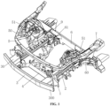
- FIG. 1 an exemplary structure of the lower vehicle-body front structure of this embodiment is shown in FIG. 1 , which mainly includes a front longitudinal beam 2 of an engine room, a front anti-collision beam 3, a rear transverse beam 6 of the engine room, a front shock absorber seat 9, an upper transverse beam 5 of a front engine room, an energy absorption box 50 of the upper transverse beam of the front engine room, and so on.
- the front anti-collision beam 3, the front longitudinal beam 2 of the engine room, the rear transverse beam 6 of the front engine room and a side beam 7 of a front wheel cover are arranged in the body frame of the front engine room.
- the rear transverse beam 6 of the front engine room is connected between two torsion boxes 60 and located between a cockpit and the front engine room.
- Two front longitudinal beams 2 of the engine room symmetrically arranged in a left-and-right direction are located in a middle and lower part of the front engine room, with their rear ends fixedly connected to the rear transverse beam 6 of the front engine room and their front ends connected to the front anti-collision beam 3.
- a front subframe 4 is provided below the front longitudinal beam 2 of the engine room.
- a connecting seat 1 is arranged between them.
- an energy absorption box 30 of the front anti-collision beam can be additionally provided between the front anti-collision beam 3 and the connecting seat 1, and the front anti-collision beam 3 and the energy absorption box 30 of the front anti-collision beam constitute a front anti-collision beam assembly.
- the front anti-collision beam 3 is connected to the connecting seat 1 through the energy absorption box 30 of the front anti-collision beam, which can improve overall collision safety of the vehicle.
- the side beam 7 of the front wheel cover is connected to an outer side of the front shock absorber seat 9, the upper transverse beam 5 of the front engine room is partially bent, with a middle part arched towards a front of the vehicle body.
- Each of both ends of the upper transverse beam 5 of the front engine room extends backward from a respective one of both sides of the vehicle body, respectively, and is connected to the side beam 7 of the front wheel cover on a corresponding side.
- Two energy absorption boxes 50 of the upper transverse beam of the front engine room are respectively arranged close to the two sides of the vehicle body, and each energy absorption box 50 of the upper transverse beam of the front engine room is connected between the upper transverse beam 5 of the front engine room and the front shock absorber seat 9 at a corresponding side.
- the upper transverse beam 5 of the front engine room and the energy absorption box 50 of the upper transverse beam of the front engine room jointly form a frame-type reinforcement structure, which provides good reinforcement and buffering and energy-absorbing effect on an upper part of the front end of the vehicle body, thus improving collision protection performance of this part.
- connection between the upper transverse beam 5 of the front engine room and the side beam 7 of the front wheel cover can be made in a welded, screwed or inserted manner.
- left and right ends of the upper transverse beam 5 of the front engine room and a front end of the side beam 7 of the front wheel cover on the corresponding side are detachably connected.
- each of both ends of the upper transverse beam 5 of the front engine room is connected to the side beam 7 of the front wheel cover at a corresponding side through a connecting plate 51 of the upper transverse beam.
- the connecting plate 51 of the upper transverse beam can be fixedly connected at an end of the upper transverse beam 5 of the front engine room by means of bolts, riveting or welding, and then a detachable connecting structure is formed between the connecting plate 51 of the upper transverse beam and the side beam 7 of the front wheel cover.
- a detachable connection structure is adopted between the upper transverse beam 5 of the front engine room and the side beam 7 of the front wheel cover, which facilitates replacement and maintenance of the upper transverse beam 5 of the front engine room.
- the connecting plate 51 of the upper transverse beam and the side beam 7 of the front wheel cover are preferably connected by a screw connection structure. That is, a plurality of sixth connecting holes 502 are formed in the front end of the front wheel side beam 7 and the connecting plate 51 of the upper transverse beam, and the front wheel side beam 7 and the connecting plate 51 of the upper transverse beam are fastened together by matching of bolts inserted into the sixth connecting holes 502 and nuts.
- this screw connection structure advantages of convenient assembly operations and reliable connection strength can be provided.
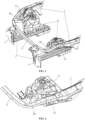
- the upper transverse beam 5 of the front engine room can be arranged in a horizontal plane, or the upper transverse beam 5 of the front engine room can be arranged in an inclined posture. As shown in FIG. 2 and FIG. 3 , along a direction towards the rear of the vehicle body, both ends of the upper transverse beam 5 of the front engine room extending in a direction towards the rear of the vehicle body in this embodiment are arranged in a gradually rising manner.
- an arched part of a front part of the upper transverse beam 5 of the front engine room can droop relatively, and when the upper transverse beam 5 of the front engine room is impacted by a large force, the upper transverse beam 5 of the front engine room can be turned downward and deformed, thus greatly alleviating an impact force and facilitating improved safety protection performance of the lower vehicle-body front structure.
- a main function of the energy absorption box 50 of the upper transverse beam of the front engine room is to form a support between the upper transverse beam 5 of the front engine room and the front shock absorber seat 9, and it can absorb energy and buffer the impact force from the upper transverse beam 5 of the front engine room by its own deformation and collapse property.
- the energy absorption box 50 of the upper transverse beam of the front engine room it is preferably arranged to be inclined outward, that is, the two energy absorption boxes 50 of the upper transverse beam of the front engine room extend obliquely outward along a direction towards a front of the vehicle body and are connected to the upper transverse beam 5 of the front engine room.
- the energy absorption box of the upper transverse beam 50 of the front engine room can be facilitated to be bent and deformed outward while collapsing and deforming itself, thus improving deformation and energy-absorbing effect of the energy absorption box of the upper transverse beam 50 of the front engine room, which is beneficial to further improving protective effect of the lower vehicle-body front structure.
- the energy absorption box 50 of the upper transverse beam of the front engine room is also detachably connected between the upper transverse beam 5 of the front engine room and the front shock absorber seat 9.
- a connecting table 90 is provided at a side of the front shock absorber seat 9.
- One end of the energy absorption box 50 of the upper transverse beam of the front engine room is connected to the connecting table 90, and the other end of the energy absorption box 50 of the upper transverse beam of the front engine room is connected to the upper transverse beam 5 of the front engine room through a connector 500.
- the connector 500 can be two plate bodies integrally formed on the energy absorption box 50 of the upper transverse beam of the front engine room, which are arranged at intervals in an up-and-down direction, and the upper transverse beam 5 of the front engine room is clamped between the two plate bodies.
- connection and mounting between the energy absorption box 50 of the upper transverse beam of the front engine room and the front shock absorber seat 9 can be facilitated.
- connection and assembly between the energy absorption box 50 of the upper transverse beam of the front engine room and the upper transverse beam 5 of the front engine room can be facilitated.
- the front end of the energy absorption box 50 of the upper transverse beam of the front engine room can be fastened by matching of bolts and nuts with the sixth connection holes 502 in the connector 500, and a rear end of the energy absorption box 50 of the upper transverse beam of the front engine room can generally be detachably connected to the connecting table 90 by screwing.
- the energy absorption box 50 of the upper transverse beam of the front engine room can adopt a multi-cavity structure, a box structure, or the like.
- the energy absorption box 50 of the upper transverse beam of the front engine room is arranged in a grid shape formed by interweaving and connecting a plurality of plate bodies 501.
- the upper transverse beam 5 of the front engine room is connected to the front longitudinal beams 2 of the engine room respectively arranged at the two sides in the vehicle body through connecting seats 1. Moreover, it is preferable that the energy absorption boxes 50 of the upper transverse beam of the front engine room at the two sides are arranged to correspond to an outer side of the connecting seat 1.
- the upper transverse beam 5 of the front engine room is fixedly connected to a top of the connecting seat 1 to form connection between the upper transverse beam 5 of the front engine room and the front longitudinal beams 2 of the engine room.
- the upper transverse beam 5 of the front engine room, the connecting seat 1, the front longitudinal beams 2 of the engine room, the front anti-collision beam 3 and the rear transverse beam 6 of the front engine room can jointly form a frame-type integral skeleton structure, which not only improves connection stability of the upper transverse beam 5 of the front engine room, but also facilitates improvement of the overall strength and protective performance of the body frame of the front engine room.
- multi-stage energy absorption can be achieved through front and rear arrangement of the connecting seat 1 and the energy absorption box 50 of the upper transverse beam of the front engine room while fully exerting a deformation and buffering function of the front arched structure in a middle part of the upper transverse beam 5 of the front engine room, which is also beneficial to improving protection ability of the front end of the vehicle body against small overlap impact.
- the upper transverse beam 5 of the front engine room can be made of high-strength profiles, such as high-strength steel, and preferably, the upper transverse beam 5 of the front engine room is made of tubular beams.
- the energy absorption box 50 of the upper transverse beam of the front engine room is preferably extruded from an aluminum alloy.
- a plurality of impact transmission and buffering paths are formed from the upper transverse beam 5 of the front engine room to the side beam 7 of the front wheel cover, from the upper transverse beam 5 of the front engine room to the energy absorption box 50 of the upper transverse beam of the front engine room, and between the upper transverse beam 5 of the front engine room and the connecting seat 1.
- a closed ring structure is formed at an upper part of the front engine room, so that safety performance of the front engine room under collision conditions is enhanced.
- the upper transverse beam 5 of the front engine room is detachably arranged, which not only does not affect maintenance of an air conditioner radiator, but also facilitates maintenance and replacement of the upper transverse beam 5 of the front engine room.
- the frame composed of the front anti-collision beam 3, the upper transverse beam 5 of the front engine room, the front longitudinal beam 2 of the engine room and the rear transverse beam 6 of the engine room provides a closed cavity for the front engine room, which improves overall stiffness of the front engine room and is beneficial to improving torsional stiffness and NVH (Noise, Vibration and Harshness) performance of the whole vehicle.
- NVH Noise, Vibration and Harshness
- both ends of the upper transverse beam 5 of the front engine room are respectively connected to front ends of the side beams 7 of the front wheel covers; and meanwhile, the energy absorption box 50 of the upper transverse beam of the front engine room is additionally provided between the upper transverse beam 5 of the front engine room and the front shock absorber seat 9, so that structural strength of an upper part of the front end of the vehicle body can be effectively improved.
- the energy absorption box 50 of the upper transverse beam of the front engine room and the front arched structure of the upper transverse beam 5 of the front engine room can absorb kinetic energy due to their own deformation and collapse, which functions well in buffering and facilitates improved collision protection performance of the front end of the vehicle body.
- a connecting seat is arranged between the front longitudinal beam 2 of the engine room and the front anti-collision beam 3.
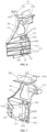
- the connecting seat includes a structural main body 1, and a connecting part 10 of the longitudinal beam and an energy absorption part 11 arranged on the structural main body 1.
- the structural main body 1 preferably adopts a plate-like structure.
- a front side of the structural main body is used to connect the front anti-collision beam 3, and the front longitudinal beam 2 of the engine room is located at a rear side of the structural main body 1.
- the connecting part 10 of the longitudinal beam of the engine room and the energy absorption part 11 are arranged at a rear side of the structural main body 1 corresponding to the front longitudinal beam 2 of the engine room, and can be at a middle or lower part of the structural main body.
- the connecting part 10 of the longitudinal beam of the engine room and the energy absorption part 11 are arranged at the lower part of the structural main body 1.
- the energy absorption part 11 is arranged at an outer part of the connecting part 10 of the longitudinal beam of the engine room and protrudes in a direction towards a rear of the structural main body 1.
- the small overlap impact from the front anti-collision beam 3 mostly occurs at its extension section 300 extending to the outer side of the front longitudinal beam 2 of the engine room.
- the extension section 300 can be bent toward the energy absorption part 11 when impacted, so that the energy absorption part 11 can absorb an impact force from the small overlap impact.
- the energy absorption part 11 when viewed in a length direction of the vehicle body, should be arranged between the extension section 300 and the energy absorption box 50 of the upper transverse beam of the front engine room, thus forming a three-stage impact buffering structure layout in which the front anti-collision beam 3 and its energy absorption box 30, the energy absorption part 11 of the connecting seat and the energy absorption box 50 of the upper transverse beam of the front engine room are arranged in sequence, which greatly improves the collision protection performance of the vehicle.
- connection hole 100 of the longitudinal beam for connecting the front longitudinal beam 2 of the engine room is respectively arranged on the connection part 10 of the longitudinal beam and the energy absorption part 11, so that the front longitudinal beam 2 of the engine room is connected and fastened to the connection part 10 of the longitudinal beam and the energy absorption part 11 at the same time, so as to ensure stability of support foundation of the energy absorption part 11.
- the energy absorption part 11 located at a lower part of a rear side of the structural main body 1 and located at an outer side may bear the impact first, so as to be deformed and collapsed, so as to greatly alleviate an impact force transmitted to the front longitudinal beam 2 of the engine room.
- the structural main body 1 is designed as a plate structure, which is not only convenient for construction, but also suitable for arrangement requirements of the connection part 10 of the longitudinal beam, the energy absorption part 11 of the engine room and the like on the structural main body 1. Arrangement positions of the connecting part 10 of the longitudinal beam and the energy absorption part 11 of the engine room on the structural main body 1 can be avoided, and lightening holes 18 can be opened at other parts. Some flanging 17 can also be formed at a part of an edge of the structural main body 1. With provision of the flanging 17 and/or the lightening holes 18 on the structural main body 1, not only overall strength of the structural main body 1 can be improved, but also weight of the structural main body 1 can be effectively reduced. Obviously, only one or both of the flange 17 and the lightening hole 18 can be provided.
- the energy absorption part 11 can be arranged in different structures, such as a box, a profile, a plate, a grid-like chamber, etc.
- the energy absorption part 11 as a whole gradually increases in a height protruding backward in a direction from an outermost side of the structural main body 1 towards the connecting part 10 of the longitudinal beam of the engine room.
- the energy absorption part 11 is designed as a gradual structure with a larger protrusion height as it gets closer to the connecting part 10 of the longitudinal beam of the engine room, which can exert gradual deformation and collapsing effect according to different impact forces, so as to achieve greater collapsing and energy-absorbing effect as it gets closer to the front longitudinal beam 2 of the engine room, which is beneficial to improving safety and effectiveness of the energy absorption part 11.
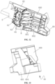
- the energy absorption part 11 includes a longitudinal plate body 111 fixedly connected to the structural main body 1 and a transverse plate body 112 fixedly connected between the structural main body 1 and the longitudinal plate body 111.
- the longitudinal plate body 111 extends backward perpendicular to the structural main body 1.
- the longitudinal plate body 111 is provided with a connection hole 100 of the longitudinal beam for fixing the front longitudinal beam 2 of the engine room.
- a mounting and connection hole 120 of the front subframe may be provided at a bottom of the energy absorption part 11 for connecting and fixing the front subframe 4 of the vehicle.
- the mounting and connection hole 120 of the front subframe is arranged at a bottom of the energy absorption part 11, which can not only meet connection and mounting requirements of the lower vehicle-body front structure of the front subframe 4, but also is beneficial to weakening transmission of the impact force from the front anti-collision beam 3 to the front subframe 4 and has certain effect on buffer protection of the front subframe 4.
- a connecting part 12 of the front subframe can be arranged between a lowermost transverse plate body 112 and an adjacent transverse plate body 112, and the mounting and connection hole 120 of the front subframe is arranged on the connecting part 12 of the front subframe, and meanwhile, the mounting and connection hole 120 of the front subframe is provided with an opening on the lowermost transverse plate body 112.
- the connecting part 12 of the front subframe can be formed by the lowermost transverse plate body 112, and the mounting and connection hole 120 of the front subframe can also be changed into a connecting rod welded at a bottom of the transverse plate body 112, and connection with the front subframe 4 can be realized by the connecting rod.
- a reinforcing plate body 13 is arranged between two adjacent transverse plate bodies 112 above. Since the plurality of transverse plate bodies 112 are arranged at intervals in an up-and-down direction, the connecting part 12 of the front subframe is provided based on the lowermost transverse plate body 112, which facilitates connection and mounting of the front subframe 4 on the energy absorption part 11. With the reinforcing plate 13 being additionally provided between the adjacent transverse plate bodies 112, connection strength between the transverse plate bodies 112 can be improved, which is beneficial to ensuring seat capacity of the connecting part 12 of the front subframe and meets mounting requirements of the front subframe 4.
- the connecting part 10 of the longitudinal beam of the engine room includes a connecting plate 101 fixedly connected to the structural main body 1.
- the connecting plate 101 is connected to the longitudinal plate body 111, and the connecting plate 101 is a semi-enclosed shape as a whole, and a connecting cavity 102 is defined between the connecting plate 101 and the longitudinal plate body 111, and an end 20 in the front of the front longitudinal beam 2 of the engine room is inserted into the connecting cavity 102.
- the connecting plate 101 is also provided with a plurality of connection holes 100 of the longitudinal beam for fixing the front longitudinal beam 2 of the engine room.
- a connecting plate 101 with two ends fixedly connected to the longitudinal plate body 111 is arranged at the connecting part 10 of the front longitudinal beam of the engine room of the structural main body 1, so that the connecting cavity 102 is formed by the connecting plate 101 and the longitudinal plate body 111 together, which facilitates inserting and connecting of the front longitudinal beam 2 of the engine room.
- the end 20 of the front longitudinal beam 2 of the engine room is fastened in the connecting cavity 102 through a plurality of longitudinal beam connecting holes 100 defined in the connecting plate 101 and the longitudinal plate body 111, and thus connection firmness between the structural main body 1 and the front longitudinal beam 2 of the engine room can be ensured.
- a specific fixing method can be to use bolts to pass through the connection hole 100 of the longitudinal beam and to be screwed into the threaded hole opened on the end 20, so as to realize fastening connection of the front longitudinal beam 2 of the engine room at the connecting part 10 of the longitudinal beam of the engine room.
- a lower part of a front side of the structural main body 1 is provided with a connecting hole 141 of the energy absorption box of the front anti-collision beam.
- the energy absorption box 30 of the front anti-collision beam is arranged between the front anti-collision beam 3 and the structural main body 1, the energy absorption box 30 of the front anti-collision beam can be fastened in the connecting hole 141 of the energy absorption box of the front anti-collision beam by bolts.
- two connecting holes 141 of the energy absorption box of the front anti-collision beam can be respectively opened at a top and a bottom of the connecting part 10 of the longitudinal beam of the engine room, and a pre-positioning post 142 of the energy absorption box of the front anti-collision beam is arranged at a position on the structural main body 1 adjacent to the connecting holes 141 of the energy absorption box of the front anti-collision beam.
- a positioning hole is provided on the energy absorption box 30 of the front anti-collision beam corresponding to the pre-positioning post 142 of the energy absorption box of the front anti-collision beam.
- the energy absorption box 30 of the front anti-collision beam In mounting the energy absorption box 30 of the front anti-collision beam, it is preferred to position the energy absorption box 30 of the front anti-collision beam by the pre-positioning post 142 of the energy absorption box of the front anti-collision beam, and to tighten the energy absorption box 30 of the front anti-collision beam by using bolts.
- a position of the energy absorption box 30 of the front anti-collision beam is just opposite to the connecting part 10 of the longitudinal beam of the engine room and the energy absorption part 11, which is beneficial for an impact force from the small overlap impact from the energy absorption box 30 of the front anti-collision beam to be directly transmitted to the energy absorption part 11, and facilitates exerting of a function of buffering and energy-absorbing of the lower vehicle-body front structure.
- a connecting bracket 15 is provided at a top of the structural main body 1, and the connecting bracket 15 can be arranged at a front side or a rear side of the structural main body 1, or at both the front side and the rear side.
- the connecting bracket 15 includes a front connecting bracket 15a and a rear connecting bracket 15b, which are used for connecting a transverse locking and mounting beam of the engine room and a front-upper beam 5 of the engine room, respectively.
- the two connecting brackets are provided with a fifth connecting hole 150, for fixing components by fasteners such as bolts. In this way, the front-upper beam 5 of the engine room and the transverse locking and mounting beam of the engine room can be centrally fixed on the connecting bracket 15.
- a radiator mounting bracket 16 is further provided on the structural main body 1 near the top for fixing a radiator.
- the connecting bracket 15 and/or the radiator mounting bracket 16 are convenient to assemble components such as the front-upper beam 5 of the engine room, the transverse locking and mounting beam of the engine room, and the radiator in the engine room of the vehicle on the lower vehicle-body front structure, so that the lower vehicle-body front structure can provide centralized connection of multiple components.
- connection seat can be in a forged or cast piece, and welded with steel profile or aluminum profile.
- cast aluminum is adopted for integral casting and molding. This configuration has characteristics of mature construction processes and light weight, with good deformation and collapsing performance of the energy absorption part 11, which is beneficial for the lower vehicle-body front structure to well exert buffering and energy-absorbing functions when the front body suffers small overlap impact.
- connection seat For the connection seat according to this embodiment, secondary energy absorption and buffering of the front anti-collision beam 3 after energy absorption is realized with high collapsing property of aluminum alloy in a case of small overlap impact, and energy absorption effect can be flexibly adjusted through a rib structure of an aluminum casting.
- the connecting seat serves to connect at its upper and lower parts, with the front-upper beam 5 of the engine room, the transverse locking and mounting beam of the engine room, and the radiator being connected at the upper part, and the energy absorption box 30 of the front anti-collision beam 3, the front longitudinal beam 2 of the engine room and the front subframe 4 being connected at the lower part, so that a connecting structure at a front part of the whole frame structure is compact, centralized and simplified. Characteristics of high integration also simplify an assembly process of the frame.
- the connecting seat described above is provided in the lower vehicle-body front structure according to this embodiment, and the connecting seat is mounted at the front end of the front longitudinal beam 2 of the engine room and connected to the front anti-collision beam 3 of the vehicle.
- the energy absorption part 11 may be collapsed and deformed after an impact force is transmitted to the structural main body 1, so as to absorb a part of impact energy.
- the front longitudinal beam 2 of the engine room is arranged in the lower vehicle-body front structure disclosed in the present application and plays an important role in supporting and transmitting a force.
- a longitudinal beam body of the front longitudinal beam 2 of the engine room includes a main body part and a reinforcement part.
- the main body part includes two main beam bodies 201 which are integrally connected in an up-and-down direction, and an interior of each main beam body 201 is arranged to be hollow, so that the main body part is provided with two cavity structures 200 arranged in the up-and-down direction.
- the reinforcement part includes a reinforcement beam body 202 integrally and fixedly connected to a rear of the main body part, and an interior of the reinforcement beam body 202 is also arranged to be hollow, so that a rear of the longitudinal beam body is provided with three cavity structures 200 arranged in the up-and-down direction.
- the longitudinal beam body adopts an integrally extruded profile structure. With above arrangement, an energy absorption area at the front end of the longitudinal beam body is provided with two sections, and a connection area at a rear end is provided with three sections, so that strength can be improved and structural and performance requirements of different parts can be met.
- Each of cross sections of the main beam body 201 and the reinforcing beam body 202 can be rectangular, hexagonal and in other different shapes.
- the cross section of the main beam body 201 is octagonal
- the cross section of the reinforcing beam body 202 is rectangular (preferably square).
- the cross section of the main beam body 201 is octagonal, so that cross sections of two parallel main body parts can be shaped like a number "8", which not only makes appearance of the main bodies standardized but also stabilizes structural strength of the main body parts, which meets design requirements for light-weighting.
- the cross section of the reinforcing beam body 202 adopts a rectangular structure, which is not only convenient for construction and molding, but also suitable for mounting and matching at a bottom and an upper part of the main body part. It should be emphasized once again that an octagonal cross-sectional structure of the main beam body 201 has high strength, and at the same time, it is less invasive to a surrounding space while ensuring that the cavity structure 200 is large enough, which facilitates rational layout of the space.
- a front end of the main body part is provided with a front connection part
- a rear end of the main body part and the reinforcement part are provided with rear connection parts for connecting the longitudinal beam body with external components located at the front end and the rear end respectively.
- the front connecting part and the rear connecting part can be surfaces to be welded for welding connection, and can also be of a plug-in mounting structure.
- the front connecting part includes first connecting holes 203 respectively provided on the two main beam bodies 201
- the rear connecting part includes second connecting holes 204 respectively arranged on the two main beam bodies 201 and the reinforcing beam body 202.
- rivet nuts 208 can be provided in advance in some or all of the first connecting holes 203 and the second connecting holes 204, so that the longitudinal beam body and the external members can be fixedly connected by a riveting process.
- Connecting holes are used to integrally connect the longitudinal beam body and external components, which is convenient for connecting and assembling by means of screwing and riveting, and has characteristics of reliable connection performance and convenient assembly operations.
- connecting holes are arranged on both the main beam body 201 and the reinforcing beam body 202, and rivet nuts 208 are provided in part or all of the connecting holes, so that riveting connection strength at the connecting holes can be improved.
- Front and rear ends of the longitudinal beam body can be specifically designed as a vertical plane-shaped notch in shape, or they can be in other shapes and structures.
- a front end of the reinforcing beam body 202 is inclined forward.
- a side and a bottom of the front end of the reinforcing beam body 202 are provided with a third connecting hole 205 for connecting the front subframe 4.
- a fourth connecting hole 206 is also provided at a bottom of the main beam body 201 below.
- the third connecting hole 205 and the fourth connecting hole 206 are matched to jointly mount the front subframe 4 under the longitudinal beam body.
- the third connection hole 205 and the fourth connection hole 206 can also be connected to the front subframe 4 by the riveting process.
- a rivet nut 208 can be provided in the third connection hole 205 and/or the fourth connection hole 206.
- the front end of the reinforcing beam body 202 is inclined forward, which can effectively expand an assembly space at a bottom of the longitudinal beam body and provide convenient conditions for mounting and arrangement of the front subframe 4.
- a shape of the reinforcing beam body 202 is adapted to characteristics of a path of an impact force transmitted from the front longitudinal beam 2 to the rear transverse beam 6 of the front engine room.
- the third connecting hole 205 and the fourth connecting hole 206 are arranged at bottoms of the reinforcing beam body 202 and its adjacent main beam body 201, which is convenient for mounting and connection of the front subframe 4 at a bottom of the front longitudinal beam 2 of the engine room.
- the rear end of the main body is also preferably inclined forward.
- a buffering space can be formed between the rear transverse beam 6 of the front engine room and an upper part of the front longitudinal beam 2 of the engine room, which is beneficial for the front longitudinal beam 2 of the engine room that has suffered too much impact to turn upward centering on its rear part when the vehicle collides seriously, thus reducing possibility that the front longitudinal beam 2 of the engine room moves straight backward and invades into the cockpit.
- an upper connecting plate 207 is provided at a top of the main body part.
- the upper connecting plate 207 extends along a length direction of the main body part, is located at a rear part of the main body part, and is arranged close to an outer side of the main body part.
- a mounting part 209 of a shock absorber seat is provided at an inner side of the upper connecting plate 207 and an inner side of the main body part below the upper connecting plate 207, and the mounting part 209 of the shock absorber seat is used for mounting and arranging the front shock absorber seat 9.
- the upper connecting plate 207 is arranged at a top of and close to an outer side of the main body part, so that a space for mounting the mounting part 209 of the shock absorber seat can be formed at an inner side of the upper connecting plate 207.
- the front longitudinal beam 2 of the engine room according to this embodiment conforms to characteristics of lightweight design and has good connection and load-seat strength.
- steel, aluminum alloy and other materials can be used to manufacture the longitudinal beam body.
- the longitudinal beam body is integrally extruded with the aluminum alloy.
- the front longitudinal beam 2 of the engine room has good collapsing and deformation performance, which is beneficial to deformation and collapsing of the front longitudinal beam 2 of the engine room when the front body is seriously collided, so as to buffer and absorb energy and reduce risk of the front longitudinal beam 2 of the engine room moving straight backwards and invading into the cockpit.
- the longitudinal beam body is designed with the main body part and the reinforcement part, and the reinforcement part is arranged at the rear part of the main body part, so that an overall weight of the longitudinal beam body can be reduced as much as possible while meeting high strength requirements of the rear part of the longitudinal beam body.
- provision of the inner cavity structures 200 of the main body part and the reinforcement part can not only make the longitudinal beam body form a good strength support structure, but also greatly reduce self-weight of the longitudinal beam body while meeting overall connection and seat strength of the front longitudinal beam 2 of the engine room.
- Lightweight design of the front longitudinal beam 2 structure of the engine room can be adopted to facilitate light-weighting of the vehicle body.
- the longitudinal beam body is integrally extruded, parts are highly integrated, and the processes are simplified, which facilitates improved processing efficiency.
- Aluminum extrusion profile is adopted, which obviously improves light-weighting.
- weight of a single vehicle can be reduced by about 12 kg.
- surrounding components can be centrally mounted or directly integrated to the longitudinal beam body while simplifying a structure, thereby further simplifying working procedure and improving the efficiency.
- the rear transverse beam 6 of the engine room is also respectively provided with a support beam 62, and the support beam 62 is arranged at an upper part of the rear end of the front longitudinal beams 2 of the engine room and is abutted against and connected to the upper part of the rear end of the front longitudinal beams 2 of the engine room.
- the upper part of the rear end of the front longitudinal beam 2 of the engine room is also designed to be inclined forward, and meanwhile, the support beam 62 is arranged corresponding to the upper part of the rear end of the front longitudinal beam 2 of the engine room, and a bottom end surface 620 of the support beam 62 also forms a forward inclined guiding surface, and the upper part of the rear end of the front longitudinal beam 2 of the engine room at least partially extends below the inclined guiding surface and partially abuts against the bottom end surface 620.
- the inclined guiding surface on the bottom end surface 620 can easily induce the front longitudinal beam 2 of the engine room to turn upward, thus slowly releasing the impact force, so as to absorb energy through deformation of the whole frame of the front engine room and reduce possibility of the front longitudinal beam 2 of the engine room invading into the cockpit.
- the connecting assembly As for the connecting assembly described above, it includes a connecting piece 61 located at an inner side the front longitudinal beam 2 of the engine room and a torsion box 60 located at outer side of the front longitudinal beam 2 of the engine room.
- the connecting piece 61 and the torsion box 60 are both connected between the front longitudinal beam 2 of the engine room and the rear transverse beam 6 of the engine room.
- the connecting assembly is designed as two parts, the connecting piece 61 and the torsion box 60, which are respectively arranged at the inner and outer sides of the rear transverse beam 6 of the front engine room, which not only facilitates connection and assembly between the front longitudinal beam 2 of the engine room and the rear transverse beam 6 of the front engine room, but also facilitates absorption of impact energy by the torsion box 60 when the front longitudinal beam 2 of the engine room turns from a root of the rear end, and functions in alleviating the impact.
- Connection between the front longitudinal beam 2 of the engine room, the connecting assembly and the rear transverse beam 6 of the engine room can be bolt connection, riveting connection, welding connection, etc.
- the rear end of the front longitudinal beam 2 of the engine room is provided with a plurality of rivet nuts 64, and the connecting piece 61 and the torsion box 60 are fixedly connected to the front longitudinal beam 2 of the engine room through bolts 8 matched on the rivet nuts 64.
- the connecting piece 61 and the torsion box 60 are also both connected to the rear transverse beam 6 of the engine room by riveting.
- the connecting piece 61 and the torsion box 60 are connected to each other at their tops and bottoms, so that a cavity body 63 is formed between the connecting piece and the torsion box, and a rear side of the rear transverse beam 6 of the engine room and the support beam 62 form a blockage for a rear port of the cavity body 63.
- the rear end of the front longitudinal beam 2 of the engine room is inserted into the cavity body 63 from a front port of the cavity body 63, thus forming connection between the front longitudinal beam 2 of the engine room and the rear transverse beam 6 of the engine room.
- the cavity body 63 can serve to form good connection and fixation for the front longitudinal beam 2 of the engine room through connection between the torsion box 60 and the connecting piece 61 and a side wall of the front longitudinal beam 2 of the engine room. Moreover, because the front longitudinal beam 2 of the engine room is inserted into the cavity body 63, a good condition for the front longitudinal beam 2 of the engine room to turn upward or outward can be provided when the front longitudinal beam 2 of the engine room is strongly impacted.
- the support beam 62 can be in a form of steel sheet metal parts or extruded aluminum alloy parts.
- the support beam 62 is generally in a form of a right-angle connecting piece, which is conformally attached to the rear transverse beam 6 of the engine room, an inner side of the front longitudinal beam 2 of the engine room, and a front end surface 621 and a bottom end surface 620 of the support beam 62, and is fixedly connected to respective components at the same time.
- a part of the connecting piece 61 is conformally arranged on the bottom end surface 620 and the front end surface 621 of the support beam 62 and is fixedly connected to the support beam 62, it is preferable to extend a part of the connecting piece 61 below the front longitudinal beam 2 of the engine room, and provide a mounting point 610 of the front subframe at this position.
- the mounting point 610 of the front subframe is arranged at a bottom of the connecting piece 61, thus providing a firm mounting point of the front subframe 4 and facilitating mounting and arrangement of the front subframe 4 under the front longitudinal beam 2 of the engine room.
- the connecting part 12 of the front subframe described above and the mounting point 610 of the front subframe provided on the connecting part 61 described below can be both used as the connecting point of the front subframe.
- the torsion box 60 is connected to an outer side of the front longitudinal beam 2 of the engine room and the rear transverse beam 6 of the engine room. Meanwhile, an inner side of an upper part of the torsion box 60 abuts against an end of the support beam 62 and is fixedly connected to the support beam 62. In this way, respective connecting assemblies between the front longitudinal beam 2 of the engine room and the rear transverse beam 6 of the engine room are integrally connected around the cavity body 63.
- the bottom end face 620 and the front end face 621 of the support beam 62 are partially covered by the connecting piece 61, and the connecting piece 61 is fixedly connected to the rear transverse beam 6 of the front engine room, the front longitudinal beam 2 of the engine room and the support beam 62 at the same time, which improves overall firmness between the support beam 62 and several adjacent components, thus providing stable mounting foundation for the front longitudinal beam 2 of the engine room.
- the torsion box 60 With provision of the torsion box 60, not only a connecting function can be realized, but also a situation that the front longitudinal beam 2 of the engine room turns and bends outward due to an oblique outward impact force when the vehicle is subjected to overlap impact can be dealt with. At this time, absorption of an impact force can be relieved to a great extent by collapsing characteristics of the torsion box 60 due to its own deformation.
- the torsion box 60 can take a form of a box, a multi-grid cavity or other structures.
- the torsion box 60 according to this embodiment includes a main plate body 600 and a reinforcing rib plate 601 provided at a side of the main plate body 600.
- at least part of the reinforcing rib plates 601 are interwoven and connected so as to define a plurality of cavity chambers 602.
- the torsion box 60 adopts a grid-like cavity chamber 602 structure, which has stable supporting effect, and can absorb large amount of impact energy through its own deformation and collapsing and have good buffering and energy absorption effect.
- a part of the torsion box 60 located at an outer side extends beyond an end of the rear transverse beam 6 of the engine room, thus forming a connection surface 603 of a sill beam connected to the sill beam 70. Furthermore, a part of a lower part of the torsion box 60 can be extended downward, and a connection surface 604 of the front transverse beam for connecting a front transverse beam of a front floor can be formed below the rear transverse beam 6 of the front engine room. Naturally, one or both of the connection surface 603 of the sill beam and the connection surface 604 of the front transverse beam may be provided.
- the torsion box 60 By extending a part of the outer side of the torsion box 60 to form a connecting surface for connecting the sill beam 70 and the front transverse beam of the front floor, the torsion box 60 can be caused to form an intermediate part, connecting surrounding components such as the front longitudinal beam 2 of the engine room, the rear transverse beam 6 of the front engine room, the sill beam 70 and the front transverse beam of the front floor, with a reasonable assembly structure and convenient assembling.
- the two front longitudinal beams 2 of the engine room are preferably arranged to be inclined outward in a whole frame structure of the front engine room. That is, in a direction towards the front of the vehicle body, the front longitudinal beams 2 of the engine room at two sides are arranged to be inclined outward to both sides of the vehicle body.
- the strong collision can induce the front longitudinal beam 2 of the engine room to turn outward, so that the torsion box 60 collapses and absorbs energy to alleviate influence of the collision on an interior of the cockpit.
- An outward inclined angle relative to the length direction of the vehicle body can be set to be about 10°, as long as layout of components in the front engine room is not affected.
- the front longitudinal beam 2 of the engine room turns upward from its rear end when an impact force from the front of the front longitudinal beam 2 of the engine room is too large, and thus a force from the impact is directed in an upward-inclined direction, so as to help reduce possibility of the front longitudinal beam 2 of the engine room invading into the cockpit when it is impacted by front collision.
- buffering and energy-absorbing structures are designed from multiple perspectives and at multiple levels, and most of components are designed to be lightweight, which greatly improves overall structural strength and collision protection performance of the front frame of the vehicle body.
- this embodiment also relates to a vehicle, a body of the vehicle is provided with the lower vehicle-body front structure as described above.
Landscapes
- Engineering & Computer Science (AREA)
- Mechanical Engineering (AREA)
- Chemical & Material Sciences (AREA)
- Combustion & Propulsion (AREA)
- Transportation (AREA)
- Architecture (AREA)
- Structural Engineering (AREA)
- Body Structure For Vehicles (AREA)
Abstract
Description
- This application claims priority to the patent application No.
202110931821.7 entitled "LOWER VEHICLE BODY FRONT STRUCTURE" filed in China National Intellectual Property Administration on August 13, 2020 - The present application relates to the technical field of body structures of vehicles, in particular to a lower vehicle-body front structure. Meanwhile, the present application also relates to a vehicle provided with the lower vehicle-body front structure.
- In design of a body frame of a front engine room of a vehicle, safety and lightweight design are important issues that are mutually influenced and need to be considered emphatically.
- In a structure of the body frame of the front engine room, a front anti-collision beam mainly functions to receive collision from front of the vehicle, and the front anti-collision beam is generally connected to a front longitudinal beam of the engine room through structures such as an energy absorption box of the front anti-collision beam and a connecting bracket. An impact force received by the front anti-collision beam is transmitted to the front longitudinal beam of the engine room along a path from the front anti-collision beam, to the energy absorption box of the front anti-collision beam and to the connecting bracket. The front anti-collision beam and the energy absorption box of the front anti-collision beam are mainly provided to deal with the collision from the front of the vehicle and to function in buffering and absorbing energy, and to prevent an excessive impact force from being directly transmitted to the front longitudinal beam of the engine room, which may further transmit the impact force to a cockpit, or even the longitudinal beam of the engine room directly invades into the cockpit and causes adverse effect on personal safety of drivers and passengers.
- In the above-mentioned body frame structure, the front anti-collision beam and the front longitudinal beam of the engine room are disposed at relatively low positions. There is no necessary collision protection measures for a radiator at a front end of the vehicle body and parts above it. When caused collision applies a great impact on an upper part of the front end of the vehicle body, an impact force is easily transmitted directly to an interior of the front engine room, causing serious damage to core components such as an engine. Moreover, due to lack of necessary protection and buffer structures, an excessive impact force may also impact and move backwards components in the front engine room, and invade into the cockpit, causing harm to drivers and passengers.
- In addition, an existing connecting bracket for connecting the front anti-collision beam and the front longitudinal beam of the engine room is fixedly mounted at a front end of the front longitudinal beam of the engine room, which is generally simple in structure and mainly functions in connection and mounting, and may also contribute to mounting and connection of surrounding components such as a front subframe and a locking and mounting transverse beam of the engine room. When the impact force from the front anti-collision beam reaches the connecting bracket, the impact force may be directly transferred to the front longitudinal beam of the engine room.
- In actual vehicle collision, there is not only impact from the front of a vehicle, but also small overlap impact from a front side of the vehicle. At this moment, an impact force from the collision comes from an end of the front anti-collision beam and is transferred towards a middle of the front engine room at an inclined angle. It is difficult to fully exert an energy absorption and buffering function of the connecting bracket and the energy absorption box of the front anti-collision beam of the bracket of the front anti-collision beam. When the impact force reaches an end of the front longitudinal beam of the engine room, it may cause huge torsional impact damage to the front longitudinal beam of the engine room, which may damage a whole body frame structure at the front engine room and cause impact damage to all components in the front engine room and even to the drivers and passengers in the cockpit.
- In view of this, the present application aims to propose a lower vehicle-body front structure to improve collision protection performance of a front body.
- To achieve above purposes, technical solutions of the present application are implemented as follows.
- The lower vehicle-body front structure includes front longitudinal beams of an engine room respectively arranged at two sides, a front anti-collision beam connected between front ends of the front longitudinal beams of the engine room at the two sides, and a rear transverse beam of the engine room connected between rear ends of the front longitudinal beams of the engine room at the two sides, the front longitudinal beams of the engine room at the two sides are respectively connected to front shock absorber seatseats;
- both ends of the front anti-collision beam are provided with an extension section extending to outside of the front longitudinal beam of the engine room;
- front ends of the front longitudinal beams of the engine room at the two sides are both connected to the front anti-collision beam through connecting seatseats, and a lower part of a rear side of each of the connecting seatseats is provided with an energy absorption part, and the energy absorption part is located at an outer side of the front longitudinal beam of the engine room and is projected towards a rear of the connecting seatseat;
- outer sides of the front shock absorber seatseats at the two sides are respectively connected to side beams of front wheel covers, and an upper transverse beam of the front engine room is connected between the side beams of the front wheel covers at the two sides, and the upper transverse beam of the front engine room is arched in a direction towards a front of a vehicle body, and an energy absorption box of the upper transverse beam of the front engine room is respectively connected between the upper transverse beam of the front engine room and each of the front shock absorber seatseats at the two sides; and
- in a direction pointing to the front of the vehicle body, the energy absorption box of the upper transverse beam of the front engine room at each side is arranged to be inclined outward, and the extension section, the energy absorption part and the energy absorption box of the upper transverse beam of the front engine room are arranged in sequence in a direction pointing to a rear of the vehicle body.
- Further, each end of the upper transverse beam of the front engine room is detachably connected to the side beam of the front wheel cover at a corresponding side; the energy absorption box of the upper transverse beam of the front engine room is detachably connected between the upper transverse beam of the front engine room and the front shock absorber seatseat; and/or,
along a direction towards the rear of the vehicle body, both ends of the upper transverse beam of the front engine room connected to the side beams of the front wheel covers at the two sides are arranged in a gradually rising manner; the energy absorption box of the upper transverse beam of the front engine room is in a grid shape formed by interweaving and connecting a plurality of plate bodies. - Further, each of the connecting seatseats includes a structural main body; the energy absorption part is located at a lower part of a rear side of the structural main body, and a connecting part of the longitudinal beam of the engine room is provided at an inner side of the energy absorption part; the connecting part of the longitudinal beam of the engine room and the energy absorption part are respectively provided with longitudinal-beam connecting holes for connecting the longitudinal beam of the engine room; and a protruding height of the energy absorption part gradually increases along a direction to the front longitudinal beam of the engine room.
- Further, the energy absorption part includes a longitudinal plate body fixedly connected to the structural main body and a transverse plate body fixedly connected between the structural main body and the longitudinal plate body, and the connecting part of the longitudinal beam of the engine room includes a connecting plate fixedly connected to the structural main body; a plurality of transverse plate bodies are arranged at intervals in an up-and-down direction, the connecting plate is connected to the longitudinal plate body, and a connecting cavity where an end of the longitudinal beam of the engine room is capable to be inserted is defined between the connecting plate and the longitudinal plate body; and the longitudinal plate body and the connecting plate are respectively provided with the longitudinal-beam connecting holes.
- Further, a connecting bracket and a radiator mounting bracket are provided at a top of the structural main body; and the upper transverse beam of the front engine room is detachably connected to the connecting bracket on each of the connecting seatseats.
- Further, the front longitudinal beam of the engine room includes a longitudinal beam body, and the longitudinal beam body is provided with a main body part and a reinforcing part; the main body part includes two main beam bodies which are integrally connected in an up-and-down direction, and an interior of each main beam body is hollow, so that the main body part is provided with two cavity structures arranged in the up-and-down direction; and the reinforcement part includes a reinforcement beam body integrally and fixedly connected to a rear of the main body part, and an interior of the reinforcement beam body is hollow, so that a rear of the longitudinal beam body is provided with three cavity structures arranged in the up-and-down direction.
- Further, a cross section of the main beam body is octagonal in shape, and a cross section of the reinforcing beam body is rectangular in shape; an upper connecting plate is provided at a top of the main body part, and the upper connecting plate extends along a length direction of the main body part and is located at the rear of the main body part, and the upper connecting plate is arranged close to an outer side of the main body part; and an inner side of the upper connecting plate and an inner side of the main body part below the upper connecting plate are configured to be connected to the front shock absorber seatseats.
- Further, rear ends of the front longitudinal beams of the engine room at the two sides are respectively connected to the rear transverse beam of the engine room through connecting assemblies, and support beams are respectively arranged on the rear transverse beam of the engine room, corresponding to the front longitudinal beams of the engine room; each of the support beams is arranged at an upper part of a rear end of the corresponding front longitudinal beam of the engine room and is abutted against and connected to the upper part of the rear end of the front longitudinal beam of the engine room.
- Further, the upper part of the rear end of the front longitudinal beam of the engine room is inclined forward; each of the support beams is arranged corresponding to the upper part of the rear end of the front longitudinal beam of the engine room, and a bottom end surface of each of the support beams is in a form of a forward inclined guiding surface; and the upper part of the rear end of the front longitudinal beam of the engine room at least partially extends below the inclined guiding surface.
- Further, each of the connecting assemblies includes a connecting plate positioned at an inner side of the front longitudinal beam of the engine room and a torsion box positioned at an outer side of the front longitudinal beam of the engine room; and the connecting plate and the torsion box are connected and enclose to form a cavity body therebetween, the rear transverse beam of the engine room and the support beams form a blockage for a rear port of the cavity body, and the rear end of the front longitudinal beam of the engine room is inserted into the cavity body through a front port of the cavity body.
- Further, the torsion box includes a main plate body and a reinforcing rib plate arranged at a side of the main plate body; a plurality of reinforcing rib plates are arranged in transverse and longitudinal directions, and at least part of the plurality of reinforcing rib plates are interwoven and connected to define a plurality of cavity chambers.
- Further, connecting points of a front subframe are respectively provided at bottoms of the connecting seats, the front longitudinal beams of the engine room and the connecting assemblies; and the lower vehicle-body front structure further includes a front subframe connected by the connecting points of the front subframe.
- Further, in the direction pointing to the front of the vehicle body, the front longitudinal beams of the engine room at the two sides are arranged to be inclined outwards to the two sides of the vehicle body; and the front anti-collision beam is connected to the connecting seat through the energy absorption box of the front anti-collision beam, and the upper transverse beam of the front engine room can be adopted in a form of a tubular beam.
- Further, the connecting seats are integrally cast and formed of cast aluminum, and the front longitudinal beams of the engine room and the rear transverse beam of the engine room are integrally extruded and formed of aluminum alloy.
- Compared with the prior art, the present application has following advantages.
- For the lower vehicle-body front structure according to the present application, with provision of the upper transverse beam of the front engine room with a front arched structure, both ends of the upper transverse beam of the front engine room are respectively connected to front ends of the side beams of the front wheel covers; and meanwhile, the energy absorption box of the upper transverse beam of the front engine room is additionally provided between the upper transverse beam of the front engine room and the front shock absorber seat, so that structural strength of an upper part of the front end of the vehicle body can be effectively improved. In addition, when the upper part of the front end of the vehicle body is subjected to impact from outside, the energy absorption box of the upper transverse beam of the front engine room and the front arched structure of the upper transverse beam of the front engine room can absorb kinetic energy due to their own deformation and collapse, which functions well in buffering and facilitates improved collision protection performance of the front end of the vehicle body.
- In addition, the front longitudinal beam of the engine room is designed with the main body part and the reinforcement part, and the reinforcement part is arranged at the rear part of the main body part, so that an overall weight of the longitudinal beam body can be reduced as much as possible while meeting high strength requirements of the rear part of the longitudinal beam body. Meanwhile, provision of the inner cavity structures of the main body part and the reinforcement part can not only make the longitudinal beam body form a good strength support structure, but also greatly reduce self-weight of the longitudinal beam body while meeting overall connection and seat strength of the front longitudinal beam of the engine room. Lightweight design of the front longitudinal beam structure of the engine room can be adopted to facilitate light-weighting of the vehicle body.
- Another object of the present application is to propose a vehicle, and a body of the vehicle is provided with the lower vehicle-body front structure as described above.
- Compared with related art, the vehicle according to the present application has same beneficial effects as the lower vehicle-body front structure, which will not be repeatedly described in detail here.
- The drawings which form a part of the present application, are used to provide a further understanding of the present application. Illustrative embodiments of the present application and their descriptions are intended to explain the present application in which related directional words such as front, rear, above and below are only used to express a relative positional relationship, and not constructed as undue limitations on the present application. In the drawings:
-
FIG. 1 is a schematic diagram of an overall structure of a lower vehicle-body front structure according to an embodiment of the present application; -
FIG. 2 is a schematic structural diagram of an energy absorption box of an upper transverse beam of a front engine room connected between surrounding components according to an embodiment of the present application; -
FIG. 3 is a schematic diagram of a partial structure shown inFIG. 2 ; -
FIG. 4 is an explosion diagram of respective components shown inFIG. 3 ; -
FIG. 5 is a schematic diagram of an assembly and connection structure of a connecting seat and a front longitudinal beam of an engine room according to an embodiment of the present application; -
FIG. 6 is a schematic structural diagram of a rear outer side of a connecting seat according to an embodiment of the present application; -
FIG. 7 is a schematic structural diagram of a rear inner side of a connecting seat according to an embodiment of the present application; -
FIG. 8 is an overall structural diagram of a front longitudinal beam of an engine room assembled in the lower vehicle-body front structure according to an embodiment of the present application; -
FIG. 9 shows a schematic diagram of a three-dimensional structure of a front longitudinal beam of an engine room according to an embodiment of the present application from an external perspective; -
FIG. 10 shows a schematic diagram of a three-dimensional structure of a front longitudinal beam of an engine room according to an embodiment of the present application from a perspective below an inner side; -
FIG. 11 shows a schematic diagram of an overall assembly structure of a connecting structure of the rear end of the front longitudinal beam of the engine room according to an embodiment of the present application from the perspective below an inner side; -
FIG. 12 is a schematic structural diagram of the connecting structure of the rear end of the front longitudinal beam of the engine room with the front longitudinal beam of the engine room removed according to an embodiment of the present application; -
FIG. 13 is a schematic structural diagram of a rear side of a torsion box according to an embodiment of the present application; and -
FIG. 14 is a top view of a lower vehicle-body front structure according to an embodiment of the present application. -
- 1. structural main body; 10. connecting part of longitudinal beam of engine room; 100. connecting hole of longitudinal beam; 101. connecting plate; 102. connecting cavity; 11. energy absorption part; 111. longitudinal plate body; 112, transverse plate body; 12. connecting part of front subframe; 120. mounting and connecting hole of front subframe ; 13. reinforcing plate body; 141. connecting hole of energy absorption box of front anti-collision beam; 142. pre-positioning post of energy absorption box of front anti-collision beam; 15. connecting bracket; 15a. front connecting bracket; 15b. rear connecting bracket; 150. fifth connecting hole; 16. radiator mounting bracket; 17. flanging; 18. lightening hole;
- 2. front longitudinal beam of engine room; 20. end; 200. cavity structure; 201. main beam body; 202. reinforcing beam body; 203. first connecting hole; 204. second connecting hole; 205. third connecting hole; 206. fourth connecting hole; 207. upper connecting plate; 208. rivet nut; 209. mounting part of shock absorber seat;
- 3. front anti-collision beam; 30. energy absorption box of front anti-collision beam; 300. extension section;
- 4. front subframe;
- 5. upper transverse beam of front engine room; 50. energy absorption box of upper transverse beam of front engine room; 51. connecting plate of transverse beam; 500. connector; 501. plate body; 502. sixth connecting hole;
- 6. rear transverse beam of engine room; 60. torque box; 600. main plate body; 61. connecting piece; 601. reinforcing rib plate; 602. cavity chamber; 603. connection surface of sill beam; 604. connection surface of front transverse beam; 610. mounting point of front subframe; 62. support beam; 620. bottom end surface; 621. front end surface; 63. cavity body;
- 7. side beam of front wheel cover; 8. bolt; 9. front shock absorber seat; 90. connection table.
- It should be noted that the embodiments in the present application and the characteristics in the embodiments can be combined mutually in the case of no conflict.
it should be noted In description of the present application that if terms such as "upper", "lower", "inner" and "rear" appear to indicate an orientation or positional relationship, they are based on orientation or positional relationships shown in the drawings, only facilitate describing of the present application and simplifying the description, rather than indicate or imply that the device or element referred to must have a specific orientation, be configured and operated in a specific orientation, and thus cannot be understood as a limitation on the present application. Terms "first" and "second" are only used for descriptive purposes and cannot be understood as indicating or implying relative importance. - In addition, in description of the present application, unless otherwise specified, terms "mounting", "connecting", "coupling" and "connector" should be understood in a broad sense. For example, "connecting" can be "fixedly connecting", or "detachably connecting" or "integrally connecting", or it can be "mechanically connecting" or "electrically connecting", or it can be "directly connecting" or "indirectly connecting through an intermediate medium", or it can be "communicating within two elements". For those ordinary skilled in the art, the specific meanings of the above terms in the present application can be understood in connection with specific situations.
- The present application will be described in details with reference to drawings and in combination with embodiments.
- This embodiment relates to a lower vehicle-body front structure, which can effectively improve collision protection performance of a front body.
- In general, the lower vehicle-body front structure includes front longitudinal beams of an engine room respectively arranged at two sides, a front anti-collision beam connected between front ends of the front longitudinal beams of the engine room at the two sides, and a rear transverse beam of the engine room connected between rear ends of the front longitudinal beams of the engine room at the two sides. The front longitudinal beams of the engine room at the two sides are respectively connected to front shock absorber seats.
- Both ends of the front anti-collision beam are provided with an extension section extending to outside of the front longitudinal beam of the engine room. Front ends of the front longitudinal beams of the engine room at the two sides are each connected to a front anti-collision beam assembly through a connecting seat, and a lower part of a rear side of a respective connecting seat is provided with an energy absorption part, and the energy absorption part is located at an outer side of the front longitudinal beam of the engine room and is projected towards a rear of the connecting seat.
- Outer sides of the front shock absorber seats at the two sides are respectively connected to side beams of front wheel covers, and an upper transverse beam of the front engine room is connected between the side beams of the front wheel covers at the two sides, and the upper transverse beam of the front engine room is arched in a direction towards a front of a vehicle body, and an energy absorption box of the upper transverse beam of the front engine room is respectively connected between the upper transverse beam of the front engine room and each of the front shock absorber seats at the two sides. In a direction towards the front of the vehicle body, the energy absorption box of the upper transverse beam of the front engine room at each side is arranged to be inclined outward, and the extension section, the energy absorption part and the energy absorption box of the upper transverse beam of the front engine room are arranged in sequence in a direction pointing to a rear of the vehicle body.
- Based on above design idea, an exemplary structure of the lower vehicle-body front structure of this embodiment is shown in
FIG. 1 , which mainly includes a frontlongitudinal beam 2 of an engine room, a front anti-collision beam 3, a reartransverse beam 6 of the engine room, a frontshock absorber seat 9, an uppertransverse beam 5 of a front engine room, anenergy absorption box 50 of the upper transverse beam of the front engine room, and so on. - For ease of understanding of solutions, firstly, general configuration of the body frame of the front engine room is illustrated.
- As shown in
FIG. 1 , the front anti-collision beam 3, the frontlongitudinal beam 2 of the engine room, the reartransverse beam 6 of the front engine room and aside beam 7 of a front wheel cover are arranged in the body frame of the front engine room. The reartransverse beam 6 of the front engine room is connected between twotorsion boxes 60 and located between a cockpit and the front engine room. Two frontlongitudinal beams 2 of the engine room symmetrically arranged in a left-and-right direction are located in a middle and lower part of the front engine room, with their rear ends fixedly connected to the reartransverse beam 6 of the front engine room and their front ends connected to the front anti-collision beam 3. Afront subframe 4 is provided below the frontlongitudinal beam 2 of the engine room. In order to facilitate connection and assembly between the front anti-collision beam 3 and the frontlongitudinal beam 2 of the engine room, a connectingseat 1 is arranged between them. Obviously, there are two connectingseats 1 symmetrically arranged. Certainly, anenergy absorption box 30 of the front anti-collision beam can be additionally provided between the front anti-collision beam 3 and the connectingseat 1, and the front anti-collision beam 3 and theenergy absorption box 30 of the front anti-collision beam constitute a front anti-collision beam assembly. The front anti-collision beam 3 is connected to the connectingseat 1 through theenergy absorption box 30 of the front anti-collision beam, which can improve overall collision safety of the vehicle. - Taking the body frame of the front engine room as an example, as shown in
FIG. 2 , in the lower vehicle-body front structure according to this embodiment, theside beam 7 of the front wheel cover is connected to an outer side of the frontshock absorber seat 9, the uppertransverse beam 5 of the front engine room is partially bent, with a middle part arched towards a front of the vehicle body. Each of both ends of the uppertransverse beam 5 of the front engine room extends backward from a respective one of both sides of the vehicle body, respectively, and is connected to theside beam 7 of the front wheel cover on a corresponding side. Twoenergy absorption boxes 50 of the upper transverse beam of the front engine room are respectively arranged close to the two sides of the vehicle body, and eachenergy absorption box 50 of the upper transverse beam of the front engine room is connected between the uppertransverse beam 5 of the front engine room and the frontshock absorber seat 9 at a corresponding side. With this arrangement, combined with theside beam 7 of the front wheel cover and the frontshock absorber seat 9, the uppertransverse beam 5 of the front engine room and theenergy absorption box 50 of the upper transverse beam of the front engine room jointly form a frame-type reinforcement structure, which provides good reinforcement and buffering and energy-absorbing effect on an upper part of the front end of the vehicle body, thus improving collision protection performance of this part. - Connection between the upper
transverse beam 5 of the front engine room and theside beam 7 of the front wheel cover can be made in a welded, screwed or inserted manner. As shown inFIG. 3 combined withFIG. 4 , in this embodiment, left and right ends of the uppertransverse beam 5 of the front engine room and a front end of theside beam 7 of the front wheel cover on the corresponding side are detachably connected. Moreover, each of both ends of the uppertransverse beam 5 of the front engine room is connected to theside beam 7 of the front wheel cover at a corresponding side through a connectingplate 51 of the upper transverse beam. Specifically, the connectingplate 51 of the upper transverse beam can be fixedly connected at an end of the uppertransverse beam 5 of the front engine room by means of bolts, riveting or welding, and then a detachable connecting structure is formed between the connectingplate 51 of the upper transverse beam and theside beam 7 of the front wheel cover. - A detachable connection structure is adopted between the upper
transverse beam 5 of the front engine room and theside beam 7 of the front wheel cover, which facilitates replacement and maintenance of the uppertransverse beam 5 of the front engine room. By fixing the connectingplate 51 of the upper transverse beam at the end of the uppertransverse beam 5 of the front engine room in advance, and then connecting the connectingplate 51 of the upper transverse beam with the front end of theside beam 7 of the front wheel cover, an intermediate part is additionally provided between the uppertransverse beam 5 of the front engine room and theside beam 7 of the front wheel cover, which not only facilitates respective construction and assembly, but also can alleviate an impact force transmitted to theside beam 7 of the front wheel cover by the impacted uppertransverse beam 5 of the front engine room. - Based on above configuration, the connecting
plate 51 of the upper transverse beam and theside beam 7 of the front wheel cover are preferably connected by a screw connection structure. That is, a plurality of sixth connectingholes 502 are formed in the front end of the frontwheel side beam 7 and the connectingplate 51 of the upper transverse beam, and the frontwheel side beam 7 and the connectingplate 51 of the upper transverse beam are fastened together by matching of bolts inserted into the sixth connectingholes 502 and nuts. With this screw connection structure, advantages of convenient assembly operations and reliable connection strength can be provided. - For arrangement of the upper
transverse beam 5 of the front engine room, the uppertransverse beam 5 of the front engine room can be arranged in a horizontal plane, or the uppertransverse beam 5 of the front engine room can be arranged in an inclined posture. As shown inFIG. 2 and FIG. 3 , along a direction towards the rear of the vehicle body, both ends of the uppertransverse beam 5 of the front engine room extending in a direction towards the rear of the vehicle body in this embodiment are arranged in a gradually rising manner. In this way, an arched part of a front part of the uppertransverse beam 5 of the front engine room can droop relatively, and when the uppertransverse beam 5 of the front engine room is impacted by a large force, the uppertransverse beam 5 of the front engine room can be turned downward and deformed, thus greatly alleviating an impact force and facilitating improved safety protection performance of the lower vehicle-body front structure. - A main function of the
energy absorption box 50 of the upper transverse beam of the front engine room is to form a support between the uppertransverse beam 5 of the front engine room and the frontshock absorber seat 9, and it can absorb energy and buffer the impact force from the uppertransverse beam 5 of the front engine room by its own deformation and collapse property. For a purpose of providing theenergy absorption box 50 of the upper transverse beam of the front engine room, it is preferably arranged to be inclined outward, that is, the twoenergy absorption boxes 50 of the upper transverse beam of the front engine room extend obliquely outward along a direction towards a front of the vehicle body and are connected to the uppertransverse beam 5 of the front engine room. With an arrangement in which the front part is inclined outward to both sides, the energy absorption box of the uppertransverse beam 50 of the front engine room can be facilitated to be bent and deformed outward while collapsing and deforming itself, thus improving deformation and energy-absorbing effect of the energy absorption box of the uppertransverse beam 50 of the front engine room, which is beneficial to further improving protective effect of the lower vehicle-body front structure. - As shown in
FIG. 4 , in order to facilitate the connection and assembly between the energy absorption box of the uppertransverse beam 50 of the front engine room and the frontshock absorber seat 9, theenergy absorption box 50 of the upper transverse beam of the front engine room according to this embodiment is also detachably connected between the uppertransverse beam 5 of the front engine room and the frontshock absorber seat 9. Specifically, a connecting table 90 is provided at a side of the frontshock absorber seat 9. One end of theenergy absorption box 50 of the upper transverse beam of the front engine room is connected to the connecting table 90, and the other end of theenergy absorption box 50 of the upper transverse beam of the front engine room is connected to the uppertransverse beam 5 of the front engine room through aconnector 500. Theconnector 500 can be two plate bodies integrally formed on theenergy absorption box 50 of the upper transverse beam of the front engine room, which are arranged at intervals in an up-and-down direction, and the uppertransverse beam 5 of the front engine room is clamped between the two plate bodies. - By arranging the connecting table 90 on the front
shock absorber seat 9, connection and mounting between theenergy absorption box 50 of the upper transverse beam of the front engine room and the frontshock absorber seat 9 can be facilitated. With arrangement of theconnector 500 at a front end of theenergy absorption box 50 of the upper transverse beam of the front engine room, connection and assembly between theenergy absorption box 50 of the upper transverse beam of the front engine room and the uppertransverse beam 5 of the front engine room can be facilitated. Similarly, the front end of theenergy absorption box 50 of the upper transverse beam of the front engine room can be fastened by matching of bolts and nuts with the sixth connection holes 502 in theconnector 500, and a rear end of theenergy absorption box 50 of the upper transverse beam of the front engine room can generally be detachably connected to the connecting table 90 by screwing. - In order to enhance collapsing and energy absorption effect of the
energy absorption box 50 of the upper transverse beam of the front engine room, theenergy absorption box 50 of the upper transverse beam of the front engine room can adopt a multi-cavity structure, a box structure, or the like. In this embodiment, theenergy absorption box 50 of the upper transverse beam of the front engine room is arranged in a grid shape formed by interweaving and connecting a plurality ofplate bodies 501. - In addition, the upper
transverse beam 5 of the front engine room is connected to the frontlongitudinal beams 2 of the engine room respectively arranged at the two sides in the vehicle body through connectingseats 1. Moreover, it is preferable that theenergy absorption boxes 50 of the upper transverse beam of the front engine room at the two sides are arranged to correspond to an outer side of the connectingseat 1. The uppertransverse beam 5 of the front engine room is fixedly connected to a top of the connectingseat 1 to form connection between the uppertransverse beam 5 of the front engine room and the frontlongitudinal beams 2 of the engine room. The uppertransverse beam 5 of the front engine room, the connectingseat 1, the frontlongitudinal beams 2 of the engine room, the front anti-collision beam 3 and the reartransverse beam 6 of the front engine room can jointly form a frame-type integral skeleton structure, which not only improves connection stability of the uppertransverse beam 5 of the front engine room, but also facilitates improvement of the overall strength and protective performance of the body frame of the front engine room. With theenergy absorption box 50 of the upper transverse beam of the front engine room being provided corresponding to the outer side of the connectingseat 1, multi-stage energy absorption can be achieved through front and rear arrangement of the connectingseat 1 and theenergy absorption box 50 of the upper transverse beam of the front engine room while fully exerting a deformation and buffering function of the front arched structure in a middle part of the uppertransverse beam 5 of the front engine room, which is also beneficial to improving protection ability of the front end of the vehicle body against small overlap impact. - As for a material of main components in the lower vehicle-body front structure according to this embodiment, the upper
transverse beam 5 of the front engine room can be made of high-strength profiles, such as high-strength steel, and preferably, the uppertransverse beam 5 of the front engine room is made of tubular beams. Theenergy absorption box 50 of the upper transverse beam of the front engine room is preferably extruded from an aluminum alloy. - With provision of the upper
transverse beam 5 of the front engine room and theenergy absorption box 50 of the upper transverse beam of the front engine room, a plurality of impact transmission and buffering paths are formed from the uppertransverse beam 5 of the front engine room to theside beam 7 of the front wheel cover, from the uppertransverse beam 5 of the front engine room to theenergy absorption box 50 of the upper transverse beam of the front engine room, and between the uppertransverse beam 5 of the front engine room and the connectingseat 1. A closed ring structure is formed at an upper part of the front engine room, so that safety performance of the front engine room under collision conditions is enhanced. The uppertransverse beam 5 of the front engine room is detachably arranged, which not only does not affect maintenance of an air conditioner radiator, but also facilitates maintenance and replacement of the uppertransverse beam 5 of the front engine room. Moreover, the frame composed of the front anti-collision beam 3, the uppertransverse beam 5 of the front engine room, the frontlongitudinal beam 2 of the engine room and the reartransverse beam 6 of the engine room provides a closed cavity for the front engine room, which improves overall stiffness of the front engine room and is beneficial to improving torsional stiffness and NVH (Noise, Vibration and Harshness) performance of the whole vehicle. - To sum up, with provision of the upper
transverse beam 5 of the front engine room with a front arched structure, both ends of the uppertransverse beam 5 of the front engine room are respectively connected to front ends of the side beams 7 of the front wheel covers; and meanwhile, theenergy absorption box 50 of the upper transverse beam of the front engine room is additionally provided between the uppertransverse beam 5 of the front engine room and the frontshock absorber seat 9, so that structural strength of an upper part of the front end of the vehicle body can be effectively improved. In addition, when the upper part of the front end of the vehicle body is subjected to impact from outside, theenergy absorption box 50 of the upper transverse beam of the front engine room and the front arched structure of the uppertransverse beam 5 of the front engine room can absorb kinetic energy due to their own deformation and collapse, which functions well in buffering and facilitates improved collision protection performance of the front end of the vehicle body. - In addition, as shown in
FIG. 5 in conjunction withFIG. 1 , in order to make the lower vehicle-body front structure according to this embodiment have functions of connection and upper protection, and function in buffering and absorbing energy against small overlap impact, a connecting seat is arranged between the frontlongitudinal beam 2 of the engine room and the front anti-collision beam 3. The connecting seat includes a structuralmain body 1, and a connectingpart 10 of the longitudinal beam and anenergy absorption part 11 arranged on the structuralmain body 1. - Specifically, the structural
main body 1 preferably adopts a plate-like structure. In its assembled state, a front side of the structural main body is used to connect the front anti-collision beam 3, and the frontlongitudinal beam 2 of the engine room is located at a rear side of the structuralmain body 1. The connectingpart 10 of the longitudinal beam of the engine room and theenergy absorption part 11 are arranged at a rear side of the structuralmain body 1 corresponding to the frontlongitudinal beam 2 of the engine room, and can be at a middle or lower part of the structural main body. Preferably, the connectingpart 10 of the longitudinal beam of the engine room and theenergy absorption part 11 are arranged at the lower part of the structuralmain body 1. In addition, theenergy absorption part 11 is arranged at an outer part of the connectingpart 10 of the longitudinal beam of the engine room and protrudes in a direction towards a rear of the structuralmain body 1. - It should be noted that the small overlap impact from the front anti-collision beam 3 mostly occurs at its
extension section 300 extending to the outer side of the frontlongitudinal beam 2 of the engine room. Theextension section 300 can be bent toward theenergy absorption part 11 when impacted, so that theenergy absorption part 11 can absorb an impact force from the small overlap impact. Moreover, when viewed in a length direction of the vehicle body, theenergy absorption part 11 should be arranged between theextension section 300 and theenergy absorption box 50 of the upper transverse beam of the front engine room, thus forming a three-stage impact buffering structure layout in which the front anti-collision beam 3 and itsenergy absorption box 30, theenergy absorption part 11 of the connecting seat and theenergy absorption box 50 of the upper transverse beam of the front engine room are arranged in sequence, which greatly improves the collision protection performance of the vehicle. - Meanwhile, a
connection hole 100 of the longitudinal beam for connecting the frontlongitudinal beam 2 of the engine room is respectively arranged on theconnection part 10 of the longitudinal beam and theenergy absorption part 11, so that the frontlongitudinal beam 2 of the engine room is connected and fastened to theconnection part 10 of the longitudinal beam and theenergy absorption part 11 at the same time, so as to ensure stability of support foundation of theenergy absorption part 11. - With above arrangement, when the impact force generated by the small overlap impact at an end of the front collision beam 3 reaches the structural
main body 1, theenergy absorption part 11 located at a lower part of a rear side of the structuralmain body 1 and located at an outer side may bear the impact first, so as to be deformed and collapsed, so as to greatly alleviate an impact force transmitted to the frontlongitudinal beam 2 of the engine room. - Moreover, the structural
main body 1 is designed as a plate structure, which is not only convenient for construction, but also suitable for arrangement requirements of theconnection part 10 of the longitudinal beam, theenergy absorption part 11 of the engine room and the like on the structuralmain body 1. Arrangement positions of the connectingpart 10 of the longitudinal beam and theenergy absorption part 11 of the engine room on the structuralmain body 1 can be avoided, and lighteningholes 18 can be opened at other parts. Someflanging 17 can also be formed at a part of an edge of the structuralmain body 1. With provision of theflanging 17 and/or the lightening holes 18 on the structuralmain body 1, not only overall strength of the structuralmain body 1 can be improved, but also weight of the structuralmain body 1 can be effectively reduced. Obviously, only one or both of theflange 17 and the lighteninghole 18 can be provided. - The
energy absorption part 11 can be arranged in different structures, such as a box, a profile, a plate, a grid-like chamber, etc. In this embodiment, as shown inFIG. 6 , theenergy absorption part 11 as a whole gradually increases in a height protruding backward in a direction from an outermost side of the structuralmain body 1 towards the connectingpart 10 of the longitudinal beam of the engine room. Theenergy absorption part 11 is designed as a gradual structure with a larger protrusion height as it gets closer to the connectingpart 10 of the longitudinal beam of the engine room, which can exert gradual deformation and collapsing effect according to different impact forces, so as to achieve greater collapsing and energy-absorbing effect as it gets closer to the frontlongitudinal beam 2 of the engine room, which is beneficial to improving safety and effectiveness of theenergy absorption part 11. - Specifically, the
energy absorption part 11 includes alongitudinal plate body 111 fixedly connected to the structuralmain body 1 and atransverse plate body 112 fixedly connected between the structuralmain body 1 and thelongitudinal plate body 111. Preferably, thelongitudinal plate body 111 extends backward perpendicular to the structuralmain body 1. There are a plurality oftransverse plate bodies 112 arranged at intervals in an up-and-down direction, which are perpendicular to both the structuralmain body 1 and thelongitudinal plate body 111. Thelongitudinal plate body 111 is provided with aconnection hole 100 of the longitudinal beam for fixing the frontlongitudinal beam 2 of the engine room. - With a structure of the
longitudinal plate body 111 and thetransverse plate bodies 112 intersecting vertically and horizontally, processing and construction can be facilitated, with good connection strength. Moreover, when theenergy absorption part 11 is deformed and collapsed, remarkable energy-absorbing and buffering effect can be achieved. - In addition, a mounting and
connection hole 120 of the front subframe may be provided at a bottom of theenergy absorption part 11 for connecting and fixing thefront subframe 4 of the vehicle. The mounting andconnection hole 120 of the front subframe is arranged at a bottom of theenergy absorption part 11, which can not only meet connection and mounting requirements of the lower vehicle-body front structure of thefront subframe 4, but also is beneficial to weakening transmission of the impact force from the front anti-collision beam 3 to thefront subframe 4 and has certain effect on buffer protection of thefront subframe 4. - When the
energy absorption part 11 adopts the structure of thelongitudinal plate body 111 and thetransverse plate bodies 112, a connectingpart 12 of the front subframe can be arranged between a lowermosttransverse plate body 112 and an adjacenttransverse plate body 112, and the mounting andconnection hole 120 of the front subframe is arranged on the connectingpart 12 of the front subframe, and meanwhile, the mounting andconnection hole 120 of the front subframe is provided with an opening on the lowermosttransverse plate body 112. In addition, the connectingpart 12 of the front subframe can be formed by the lowermosttransverse plate body 112, and the mounting andconnection hole 120 of the front subframe can also be changed into a connecting rod welded at a bottom of thetransverse plate body 112, and connection with thefront subframe 4 can be realized by the connecting rod. - Meanwhile, corresponding to the connecting
part 12 of the front subframe, a reinforcingplate body 13 is arranged between two adjacenttransverse plate bodies 112 above. Since the plurality oftransverse plate bodies 112 are arranged at intervals in an up-and-down direction, the connectingpart 12 of the front subframe is provided based on the lowermosttransverse plate body 112, which facilitates connection and mounting of thefront subframe 4 on theenergy absorption part 11. With the reinforcingplate 13 being additionally provided between the adjacenttransverse plate bodies 112, connection strength between thetransverse plate bodies 112 can be improved, which is beneficial to ensuring seat capacity of the connectingpart 12 of the front subframe and meets mounting requirements of thefront subframe 4. - As shown in
FIG. 6 combined withFIG. 7 , the connectingpart 10 of the longitudinal beam of the engine room according to this embodiment includes a connectingplate 101 fixedly connected to the structuralmain body 1. The connectingplate 101 is connected to thelongitudinal plate body 111, and the connectingplate 101 is a semi-enclosed shape as a whole, and a connectingcavity 102 is defined between the connectingplate 101 and thelongitudinal plate body 111, and anend 20 in the front of the frontlongitudinal beam 2 of the engine room is inserted into the connectingcavity 102. The connectingplate 101 is also provided with a plurality of connection holes 100 of the longitudinal beam for fixing the frontlongitudinal beam 2 of the engine room. A connectingplate 101 with two ends fixedly connected to thelongitudinal plate body 111 is arranged at the connectingpart 10 of the front longitudinal beam of the engine room of the structuralmain body 1, so that the connectingcavity 102 is formed by the connectingplate 101 and thelongitudinal plate body 111 together, which facilitates inserting and connecting of the frontlongitudinal beam 2 of the engine room. Theend 20 of the frontlongitudinal beam 2 of the engine room is fastened in the connectingcavity 102 through a plurality of longitudinalbeam connecting holes 100 defined in the connectingplate 101 and thelongitudinal plate body 111, and thus connection firmness between the structuralmain body 1 and the frontlongitudinal beam 2 of the engine room can be ensured. A specific fixing method can be to use bolts to pass through theconnection hole 100 of the longitudinal beam and to be screwed into the threaded hole opened on theend 20, so as to realize fastening connection of the frontlongitudinal beam 2 of the engine room at the connectingpart 10 of the longitudinal beam of the engine room. - As shown in
FIG. 5 andFIG. 1 , a lower part of a front side of the structuralmain body 1 is provided with a connectinghole 141 of the energy absorption box of the front anti-collision beam. When theenergy absorption box 30 of the front anti-collision beam is arranged between the front anti-collision beam 3 and the structuralmain body 1, theenergy absorption box 30 of the front anti-collision beam can be fastened in the connectinghole 141 of the energy absorption box of the front anti-collision beam by bolts. Specifically, two connectingholes 141 of the energy absorption box of the front anti-collision beam can be respectively opened at a top and a bottom of the connectingpart 10 of the longitudinal beam of the engine room, and apre-positioning post 142 of the energy absorption box of the front anti-collision beam is arranged at a position on the structuralmain body 1 adjacent to the connectingholes 141 of the energy absorption box of the front anti-collision beam. A positioning hole is provided on theenergy absorption box 30 of the front anti-collision beam corresponding to thepre-positioning post 142 of the energy absorption box of the front anti-collision beam. In mounting theenergy absorption box 30 of the front anti-collision beam, it is preferred to position theenergy absorption box 30 of the front anti-collision beam by thepre-positioning post 142 of the energy absorption box of the front anti-collision beam, and to tighten theenergy absorption box 30 of the front anti-collision beam by using bolts. With above arrangement, not only assembly operations can be facilitated, but also a position of theenergy absorption box 30 of the front anti-collision beam is just opposite to the connectingpart 10 of the longitudinal beam of the engine room and theenergy absorption part 11, which is beneficial for an impact force from the small overlap impact from theenergy absorption box 30 of the front anti-collision beam to be directly transmitted to theenergy absorption part 11, and facilitates exerting of a function of buffering and energy-absorbing of the lower vehicle-body front structure. - In addition, a connecting
bracket 15 is provided at a top of the structuralmain body 1, and the connectingbracket 15 can be arranged at a front side or a rear side of the structuralmain body 1, or at both the front side and the rear side. In this embodiment, the connectingbracket 15 includes a front connectingbracket 15a and a rear connectingbracket 15b, which are used for connecting a transverse locking and mounting beam of the engine room and a front-upper beam 5 of the engine room, respectively. Meanwhile, the two connecting brackets are provided with a fifth connectinghole 150, for fixing components by fasteners such as bolts. In this way, the front-upper beam 5 of the engine room and the transverse locking and mounting beam of the engine room can be centrally fixed on the connectingbracket 15. - Meanwhile, a
radiator mounting bracket 16 is further provided on the structuralmain body 1 near the top for fixing a radiator. By arranging the connectingbracket 15 and/or theradiator mounting bracket 16 at the top of the structuralmain body 1, it is convenient to assemble components such as the front-upper beam 5 of the engine room, the transverse locking and mounting beam of the engine room, and the radiator in the engine room of the vehicle on the lower vehicle-body front structure, so that the lower vehicle-body front structure can provide centralized connection of multiple components. - The connection seat can be in a forged or cast piece, and welded with steel profile or aluminum profile. Preferably, cast aluminum is adopted for integral casting and molding. This configuration has characteristics of mature construction processes and light weight, with good deformation and collapsing performance of the
energy absorption part 11, which is beneficial for the lower vehicle-body front structure to well exert buffering and energy-absorbing functions when the front body suffers small overlap impact. - For the connection seat according to this embodiment, secondary energy absorption and buffering of the front anti-collision beam 3 after energy absorption is realized with high collapsing property of aluminum alloy in a case of small overlap impact, and energy absorption effect can be flexibly adjusted through a rib structure of an aluminum casting. In a whole frame structure of the engine room, the connecting seat serves to connect at its upper and lower parts, with the front-
upper beam 5 of the engine room, the transverse locking and mounting beam of the engine room, and the radiator being connected at the upper part, and theenergy absorption box 30 of the front anti-collision beam 3, the frontlongitudinal beam 2 of the engine room and thefront subframe 4 being connected at the lower part, so that a connecting structure at a front part of the whole frame structure is compact, centralized and simplified. Characteristics of high integration also simplify an assembly process of the frame. - Furthermore, the connecting seat described above is provided in the lower vehicle-body front structure according to this embodiment, and the connecting seat is mounted at the front end of the front
longitudinal beam 2 of the engine room and connected to the front anti-collision beam 3 of the vehicle. By designing theenergy absorption part 11 at an outer side of the structuralmain body 1, when the front anti-collision beam 3 is subjected to small offset impact from side front, theenergy absorption part 11 may be collapsed and deformed after an impact force is transmitted to the structuralmain body 1, so as to absorb a part of impact energy. Only then can a remaining part of the impact force be transmitted to the frontlongitudinal beam 2 of the engine room, so that an impact force transmitted from the frontlongitudinal beam 2 of the engine room to a cockpit is weakened, which facilitates improved cushioning and energy absorption effect of the front body when it is subjected to small overlap impact. - For the front
longitudinal beam 2 of the engine room according to this embodiment, it is arranged in the lower vehicle-body front structure disclosed in the present application and plays an important role in supporting and transmitting a force. In order to exert good performance, as shown inFIGS. 8 to 10 , it is preferable to adopt a following structure. - A longitudinal beam body of the front
longitudinal beam 2 of the engine room includes a main body part and a reinforcement part. The main body part includes twomain beam bodies 201 which are integrally connected in an up-and-down direction, and an interior of eachmain beam body 201 is arranged to be hollow, so that the main body part is provided with twocavity structures 200 arranged in the up-and-down direction. Moreover, the reinforcement part includes areinforcement beam body 202 integrally and fixedly connected to a rear of the main body part, and an interior of thereinforcement beam body 202 is also arranged to be hollow, so that a rear of the longitudinal beam body is provided with threecavity structures 200 arranged in the up-and-down direction. In order to facilitate construction, the longitudinal beam body adopts an integrally extruded profile structure. With above arrangement, an energy absorption area at the front end of the longitudinal beam body is provided with two sections, and a connection area at a rear end is provided with three sections, so that strength can be improved and structural and performance requirements of different parts can be met. - Each of cross sections of the
main beam body 201 and the reinforcingbeam body 202 can be rectangular, hexagonal and in other different shapes. Preferably, in this embodiment, the cross section of themain beam body 201 is octagonal, and the cross section of the reinforcingbeam body 202 is rectangular (preferably square). The cross section of themain beam body 201 is octagonal, so that cross sections of two parallel main body parts can be shaped like a number "8", which not only makes appearance of the main bodies standardized but also stabilizes structural strength of the main body parts, which meets design requirements for light-weighting. The cross section of the reinforcingbeam body 202 adopts a rectangular structure, which is not only convenient for construction and molding, but also suitable for mounting and matching at a bottom and an upper part of the main body part. It should be emphasized once again that an octagonal cross-sectional structure of themain beam body 201 has high strength, and at the same time, it is less invasive to a surrounding space while ensuring that thecavity structure 200 is large enough, which facilitates rational layout of the space. - In order to facilitate assembly and connection of the longitudinal beam body with external components such as a front bumper and the rear
transverse beam 6 of the front engine room, a front end of the main body part is provided with a front connection part, and a rear end of the main body part and the reinforcement part are provided with rear connection parts for connecting the longitudinal beam body with external components located at the front end and the rear end respectively. With arrangement of the front connecting part and the rear connecting part, it is convenient to connect the longitudinal beam body with external members at the front and rear ends, thus forming the body frame of the front engine room. - The front connecting part and the rear connecting part can be surfaces to be welded for welding connection, and can also be of a plug-in mounting structure. In this embodiment, the front connecting part includes first connecting
holes 203 respectively provided on the twomain beam bodies 201, and the rear connecting part includes second connectingholes 204 respectively arranged on the twomain beam bodies 201 and the reinforcingbeam body 202. Moreover, rivetnuts 208 can be provided in advance in some or all of the first connectingholes 203 and the second connectingholes 204, so that the longitudinal beam body and the external members can be fixedly connected by a riveting process. Connecting holes are used to integrally connect the longitudinal beam body and external components, which is convenient for connecting and assembling by means of screwing and riveting, and has characteristics of reliable connection performance and convenient assembly operations. Especially when riveting is adopted, connecting holes are arranged on both themain beam body 201 and the reinforcingbeam body 202, and rivetnuts 208 are provided in part or all of the connecting holes, so that riveting connection strength at the connecting holes can be improved. - Front and rear ends of the longitudinal beam body can be specifically designed as a vertical plane-shaped notch in shape, or they can be in other shapes and structures.
- As shown in
FIGS. 9 and10 , in each beam body in the longitudinal beam body, a front end of the reinforcingbeam body 202 is inclined forward. In addition, a side and a bottom of the front end of the reinforcingbeam body 202 are provided with a third connectinghole 205 for connecting thefront subframe 4. Adjacent to the front end of the reinforcingbeam body 202, a fourth connectinghole 206 is also provided at a bottom of themain beam body 201 below. The third connectinghole 205 and the fourth connectinghole 206 are matched to jointly mount thefront subframe 4 under the longitudinal beam body. Preferably, thethird connection hole 205 and thefourth connection hole 206 can also be connected to thefront subframe 4 by the riveting process. When riveting is adopted, arivet nut 208 can be provided in thethird connection hole 205 and/or thefourth connection hole 206. - The front end of the reinforcing
beam body 202 is inclined forward, which can effectively expand an assembly space at a bottom of the longitudinal beam body and provide convenient conditions for mounting and arrangement of thefront subframe 4. Moreover, a shape of the reinforcingbeam body 202 is adapted to characteristics of a path of an impact force transmitted from the frontlongitudinal beam 2 to the reartransverse beam 6 of the front engine room. The third connectinghole 205 and the fourth connectinghole 206 are arranged at bottoms of the reinforcingbeam body 202 and its adjacentmain beam body 201, which is convenient for mounting and connection of thefront subframe 4 at a bottom of the frontlongitudinal beam 2 of the engine room. - The rear end of the main body is also preferably inclined forward. With this arrangement, a buffering space can be formed between the rear
transverse beam 6 of the front engine room and an upper part of the frontlongitudinal beam 2 of the engine room, which is beneficial for the frontlongitudinal beam 2 of the engine room that has suffered too much impact to turn upward centering on its rear part when the vehicle collides seriously, thus reducing possibility that the frontlongitudinal beam 2 of the engine room moves straight backward and invades into the cockpit. - In addition, in this embodiment, an upper connecting
plate 207 is provided at a top of the main body part. Preferably, the upper connectingplate 207 extends along a length direction of the main body part, is located at a rear part of the main body part, and is arranged close to an outer side of the main body part. Based on above arrangement, a mountingpart 209 of a shock absorber seat is provided at an inner side of the upper connectingplate 207 and an inner side of the main body part below the upper connectingplate 207, and the mountingpart 209 of the shock absorber seat is used for mounting and arranging the frontshock absorber seat 9. The upper connectingplate 207 is arranged at a top of and close to an outer side of the main body part, so that a space for mounting the mountingpart 209 of the shock absorber seat can be formed at an inner side of the upper connectingplate 207. By arranging mounting holes or the like on the top of the main body part at the inner side of the upper connectingplate 207 and the upper connectingplate 207, it is convenient to fix the frontshock absorber seat 9 at the mountingpart 209 of the shock absorber seat so as to mount the shock absorber of the engine assembly. - It can be seen from above description that the front
longitudinal beam 2 of the engine room according to this embodiment conforms to characteristics of lightweight design and has good connection and load-seat strength. Based on above structural requirements, steel, aluminum alloy and other materials can be used to manufacture the longitudinal beam body. However, it is preferred that the longitudinal beam body is integrally extruded with the aluminum alloy. With aluminum profile being extruded to construct the longitudinal beam body, there are characteristics of mature construction processes and light weight, and the frontlongitudinal beam 2 of the engine room has good collapsing and deformation performance, which is beneficial to deformation and collapsing of the frontlongitudinal beam 2 of the engine room when the front body is seriously collided, so as to buffer and absorb energy and reduce risk of the frontlongitudinal beam 2 of the engine room moving straight backwards and invading into the cockpit. - For the front
longitudinal beam 2 of the engine room described in this embodiment, the longitudinal beam body is designed with the main body part and the reinforcement part, and the reinforcement part is arranged at the rear part of the main body part, so that an overall weight of the longitudinal beam body can be reduced as much as possible while meeting high strength requirements of the rear part of the longitudinal beam body. Meanwhile, provision of theinner cavity structures 200 of the main body part and the reinforcement part can not only make the longitudinal beam body form a good strength support structure, but also greatly reduce self-weight of the longitudinal beam body while meeting overall connection and seat strength of the frontlongitudinal beam 2 of the engine room. Lightweight design of the frontlongitudinal beam 2 structure of the engine room can be adopted to facilitate light-weighting of the vehicle body. - Meanwhile, the longitudinal beam body is integrally extruded, parts are highly integrated, and the processes are simplified, which facilitates improved processing efficiency. Aluminum extrusion profile is adopted, which obviously improves light-weighting. Compared with a traditional steel front longitudinal beam, weight of a single vehicle can be reduced by about 12 kg. Moreover, by arranging a plurality of connection and mounting parts on the longitudinal beam body, surrounding components can be centrally mounted or directly integrated to the longitudinal beam body while simplifying a structure, thereby further simplifying working procedure and improving the efficiency.
- In addition, when the rear end of the front
longitudinal beam 2 of the engine room is connected to the reartransverse beam 6 of the engine room, a following connection structure of the rear end of the front longitudinal beam of the engine room is adopted. - As shown in
FIG. 11 to FIG. 13 , in this embodiment, corresponding to the frontlongitudinal beams 2 of the engine room at two sides, the reartransverse beam 6 of the engine room is also respectively provided with asupport beam 62, and thesupport beam 62 is arranged at an upper part of the rear end of the frontlongitudinal beams 2 of the engine room and is abutted against and connected to the upper part of the rear end of the frontlongitudinal beams 2 of the engine room. In addition, as a preferred embodiment, the upper part of the rear end of the frontlongitudinal beam 2 of the engine room is also designed to be inclined forward, and meanwhile, thesupport beam 62 is arranged corresponding to the upper part of the rear end of the frontlongitudinal beam 2 of the engine room, and abottom end surface 620 of thesupport beam 62 also forms a forward inclined guiding surface, and the upper part of the rear end of the frontlongitudinal beam 2 of the engine room at least partially extends below the inclined guiding surface and partially abuts against thebottom end surface 620. In such a set state, when the frontlongitudinal beam 2 of the engine room is subjected to a strong impact, the inclined guiding surface on thebottom end surface 620 can easily induce the frontlongitudinal beam 2 of the engine room to turn upward, thus slowly releasing the impact force, so as to absorb energy through deformation of the whole frame of the front engine room and reduce possibility of the frontlongitudinal beam 2 of the engine room invading into the cockpit. - As for the connecting assembly described above, it includes a connecting
piece 61 located at an inner side the frontlongitudinal beam 2 of the engine room and atorsion box 60 located at outer side of the frontlongitudinal beam 2 of the engine room. The connectingpiece 61 and thetorsion box 60 are both connected between the frontlongitudinal beam 2 of the engine room and the reartransverse beam 6 of the engine room. The connecting assembly is designed as two parts, the connectingpiece 61 and thetorsion box 60, which are respectively arranged at the inner and outer sides of the reartransverse beam 6 of the front engine room, which not only facilitates connection and assembly between the frontlongitudinal beam 2 of the engine room and the reartransverse beam 6 of the front engine room, but also facilitates absorption of impact energy by thetorsion box 60 when the frontlongitudinal beam 2 of the engine room turns from a root of the rear end, and functions in alleviating the impact. - Connection between the front
longitudinal beam 2 of the engine room, the connecting assembly and the reartransverse beam 6 of the engine room can be bolt connection, riveting connection, welding connection, etc. In this embodiment, the rear end of the frontlongitudinal beam 2 of the engine room is provided with a plurality ofrivet nuts 64, and the connectingpiece 61 and thetorsion box 60 are fixedly connected to the frontlongitudinal beam 2 of the engine room throughbolts 8 matched on the rivet nuts 64. Meanwhile, the connectingpiece 61 and thetorsion box 60 are also both connected to the reartransverse beam 6 of the engine room by riveting. By riveting and addingrivet nuts 64, it not only facilitates connection and assembly between the frontlongitudinal beam 2 of the engine room and surrounding components, but also facilitates improved strength of a connection part of the components, especially suitable for connection and mounting between aluminum alloy profiles. - As for the structure of the connecting assembly, specifically, as shown in
FIG. 12 , the connectingpiece 61 and thetorsion box 60 are connected to each other at their tops and bottoms, so that acavity body 63 is formed between the connecting piece and the torsion box, and a rear side of the reartransverse beam 6 of the engine room and thesupport beam 62 form a blockage for a rear port of thecavity body 63. At this moment, the rear end of the frontlongitudinal beam 2 of the engine room is inserted into thecavity body 63 from a front port of thecavity body 63, thus forming connection between the frontlongitudinal beam 2 of the engine room and the reartransverse beam 6 of the engine room. In this design, thecavity body 63 can serve to form good connection and fixation for the frontlongitudinal beam 2 of the engine room through connection between thetorsion box 60 and the connectingpiece 61 and a side wall of the frontlongitudinal beam 2 of the engine room. Moreover, because the frontlongitudinal beam 2 of the engine room is inserted into thecavity body 63, a good condition for the frontlongitudinal beam 2 of the engine room to turn upward or outward can be provided when the frontlongitudinal beam 2 of the engine room is strongly impacted. - As shown in
FIG. 11 , thesupport beam 62 can be in a form of steel sheet metal parts or extruded aluminum alloy parts. Structurally, thesupport beam 62 is generally in a form of a right-angle connecting piece, which is conformally attached to the reartransverse beam 6 of the engine room, an inner side of the frontlongitudinal beam 2 of the engine room, and afront end surface 621 and abottom end surface 620 of thesupport beam 62, and is fixedly connected to respective components at the same time. Except that a part of the connectingpiece 61 is conformally arranged on thebottom end surface 620 and thefront end surface 621 of thesupport beam 62 and is fixedly connected to thesupport beam 62, it is preferable to extend a part of the connectingpiece 61 below the frontlongitudinal beam 2 of the engine room, and provide amounting point 610 of the front subframe at this position. The mountingpoint 610 of the front subframe is arranged at a bottom of the connectingpiece 61, thus providing a firm mounting point of thefront subframe 4 and facilitating mounting and arrangement of thefront subframe 4 under the frontlongitudinal beam 2 of the engine room. The connectingpart 12 of the front subframe described above and themounting point 610 of the front subframe provided on the connectingpart 61 described below can be both used as the connecting point of the front subframe. - The
torsion box 60 is connected to an outer side of the frontlongitudinal beam 2 of the engine room and the reartransverse beam 6 of the engine room. Meanwhile, an inner side of an upper part of thetorsion box 60 abuts against an end of thesupport beam 62 and is fixedly connected to thesupport beam 62. In this way, respective connecting assemblies between the frontlongitudinal beam 2 of the engine room and the reartransverse beam 6 of the engine room are integrally connected around thecavity body 63. Thebottom end face 620 and thefront end face 621 of thesupport beam 62 are partially covered by the connectingpiece 61, and the connectingpiece 61 is fixedly connected to the reartransverse beam 6 of the front engine room, the frontlongitudinal beam 2 of the engine room and thesupport beam 62 at the same time, which improves overall firmness between thesupport beam 62 and several adjacent components, thus providing stable mounting foundation for the frontlongitudinal beam 2 of the engine room. - With provision of the
torsion box 60, not only a connecting function can be realized, but also a situation that the frontlongitudinal beam 2 of the engine room turns and bends outward due to an oblique outward impact force when the vehicle is subjected to overlap impact can be dealt with. At this time, absorption of an impact force can be relieved to a great extent by collapsing characteristics of thetorsion box 60 due to its own deformation. - Based on above requirements, the
torsion box 60 can take a form of a box, a multi-grid cavity or other structures. Specifically, thetorsion box 60 according to this embodiment includes amain plate body 600 and a reinforcingrib plate 601 provided at a side of themain plate body 600. There are a plurality of reinforcingrib plates 601 arranged in transverse and longitudinal directions. In addition, at least part of the reinforcingrib plates 601 are interwoven and connected so as to define a plurality ofcavity chambers 602. Thetorsion box 60 adopts a grid-like cavity chamber 602 structure, which has stable supporting effect, and can absorb large amount of impact energy through its own deformation and collapsing and have good buffering and energy absorption effect. - In addition, as shown in
FIG. 12 in conjunction withFIG. 13 , in an overall structure of thetorsion box 60, a part of thetorsion box 60 located at an outer side extends beyond an end of the reartransverse beam 6 of the engine room, thus forming aconnection surface 603 of a sill beam connected to the sill beam 70. Furthermore, a part of a lower part of thetorsion box 60 can be extended downward, and aconnection surface 604 of the front transverse beam for connecting a front transverse beam of a front floor can be formed below the reartransverse beam 6 of the front engine room. Naturally, one or both of theconnection surface 603 of the sill beam and theconnection surface 604 of the front transverse beam may be provided. - By extending a part of the outer side of the
torsion box 60 to form a connecting surface for connecting the sill beam 70 and the front transverse beam of the front floor, thetorsion box 60 can be caused to form an intermediate part, connecting surrounding components such as the frontlongitudinal beam 2 of the engine room, the reartransverse beam 6 of the front engine room, the sill beam 70 and the front transverse beam of the front floor, with a reasonable assembly structure and convenient assembling. - As shown in
FIG. 14 , in order to fully exert functions of thetorsion box 60 in a case of a strong collision, the two frontlongitudinal beams 2 of the engine room are preferably arranged to be inclined outward in a whole frame structure of the front engine room. That is, in a direction towards the front of the vehicle body, the frontlongitudinal beams 2 of the engine room at two sides are arranged to be inclined outward to both sides of the vehicle body. In this way, the strong collision can induce the frontlongitudinal beam 2 of the engine room to turn outward, so that thetorsion box 60 collapses and absorbs energy to alleviate influence of the collision on an interior of the cockpit. An outward inclined angle relative to the length direction of the vehicle body can be set to be about 10°, as long as layout of components in the front engine room is not affected. - For the connecting structure at the rear end of the front longitudinal beam of the engine room described in this embodiment, by constructing a forward-inclined shape at the upper part of the rear end of the front
longitudinal beam 2 of the engine room and cooperating with inclined guiding of thebottom end surface 620 of the supportingbeam 62, the frontlongitudinal beam 2 of the engine room turns upward from its rear end when an impact force from the front of the frontlongitudinal beam 2 of the engine room is too large, and thus a force from the impact is directed in an upward-inclined direction, so as to help reduce possibility of the frontlongitudinal beam 2 of the engine room invading into the cockpit when it is impacted by front collision. - To sum up, in the lower vehicle-body front structure according to this embodiment, buffering and energy-absorbing structures are designed from multiple perspectives and at multiple levels, and most of components are designed to be lightweight, which greatly improves overall structural strength and collision protection performance of the front frame of the vehicle body.
- Finally, this embodiment also relates to a vehicle, a body of the vehicle is provided with the lower vehicle-body front structure as described above.
- The above description is only the preferred embodiments of the present application, and it is not intended to limit the present application. Any modification, equivalent substitution, improvement, etc. made within the spirit and principle of the present application shall be encompassed within the protection scope of the present application.
Claims (15)
- A lower vehicle-body front structure, comprising front longitudinal beams (2) of an engine room respectively arranged at two sides, a front anti-collision beam (3) connected between front ends of the front longitudinal beams (2) of the engine room at the two sides, and a rear transverse beam (6) of the engine room connected between rear ends of the front longitudinal beams (2) of the engine room at the two sides, wherein the front longitudinal beams (2) of the engine room at the two sides are respectively connected to front shock absorber seats (9), characterized in thatboth ends of the front anti-collision beam (3) are respectively provided with an extension section (300) extending to outside of the front longitudinal beam (2) of the engine room;front ends of the front longitudinal beams (2) of the engine room at the two sides are both connected to the front anti-collision beam (3) through connecting seats, and a lower part of a rear side of each of the connecting seats is provided with an energy absorption part (11), and the energy absorption part (11) is located at an outer side of the front longitudinal beam (2) of the engine room and is projected towards a rear of the connecting seat;outer sides of the front shock absorber seats (9) at the two sides are respectively connected to side beams (7) of front wheel covers, and an upper transverse beam (5) of the front engine room is connected between the side beams (7) of the front wheel covers at the two sides, the upper transverse beam (5) of the front engine room is arched in a direction towards a front of a vehicle body, and an energy absorption box (50) of the upper transverse beam of the front engine room is respectively connected between the upper transverse beam (5) of the front engine room and each of the front shock absorber seats (9) at the two sides; andin a direction pointing to the front of the vehicle body, the energy absorption box (50) of the upper transverse beam of the front engine room at each side is arranged to be inclined outward, and the extension section (300), the energy absorption part (11) and the energy absorption box (50) of the upper transverse beam of the front engine room are arranged in sequence in a direction pointing to a rear of the vehicle body.
- The lower vehicle-body front structure according to claim 1, characterized in thateach end of the upper transverse beam (5) of the front engine room is detachably connected to the side beam (7) of the front wheel cover at a corresponding side, and the energy absorption box (50) of the upper transverse beam of the front engine room is detachably connected between the upper transverse beam (5) of the front engine room and each of the front shock absorber seats (9); and/or,along a direction towards the rear of the vehicle body, both ends of the upper transverse beam (5) of the front engine room connected to the side beams (7) of the front wheel covers at the two sides are arranged in a gradually rising manner; and the energy absorption box (50) of the upper transverse beam of the front engine room is in a grid shape formed by interweaving and connecting a plurality of plate bodies (501).
- The lower vehicle-body front structure according to claim 1, characterized in thateach of the connecting seats comprises a structural main body (1);the energy absorption part (11) is located at a lower part of a rear side of the structural main body (1), and a connecting part (10) of the longitudinal beam of the engine room is provided at an inner side of the energy absorption part (11);the connecting part (10) of the longitudinal beam of the engine room and the energy absorption part (11) are respectively provided with longitudinal-beam connecting holes (100) for connecting the longitudinal beam of the engine room; anda protruding height of the energy absorption part (11) gradually increases along a direction to the front longitudinal beam (2) of the engine room.
- The lower vehicle-body front structure according to claim 3, characterized in thatthe energy absorption part (11) comprises a longitudinal plate body (111) fixedly connected to the structural main body (1) and a transverse plate body (112) fixedly connected between the structural main body (1) and the longitudinal plate body (111), and the connecting part (10) of the longitudinal beam of the engine room comprises a connecting plate (101) fixedly connected to the structural main body (1);a plurality of transverse plate bodies (112) are arranged at intervals in an up-and-down direction, the connecting plate (101) is connected to the longitudinal plate body (111), and a connecting cavity (102) where an end (20) of the longitudinal beam of the engine room is capable to be inserted is defined between the connecting plate (101) and the longitudinal plate body (111); andthe longitudinal plate body (111) and the connecting plate (101) are respectively provided with the longitudinal-beam connecting holes (100).
- The lower vehicle-body front structure according to claim 3, characterized in thata connecting bracket (15) and a radiator mounting bracket (16) are provided at a top of the structural main body (1); andthe upper transverse beam (5) of the front engine room is detachably connected to the connecting bracket (15) on each of the connecting seats.
- The lower vehicle-body front structure according to claim 1, characterized in thatthe front longitudinal beam (2) of the engine room comprises a longitudinal beam body, and the longitudinal beam body is provided with a main body part and a reinforcing part;the main body part comprises two main beam bodies (201) which are integrally connected in an up-and-down direction, and an interior of each main beam body (201) is hollow, so that the main body part is provided with two cavity structures (200) arranged in the up-and-down direction; andthe reinforcement part includes a reinforcement beam body (202) integrally and fixedly connected to a rear of the main body part, and an interior of the reinforcement beam body (202) is hollow, so that a rear of the longitudinal beam body is provided with three cavity structures (200) arranged in the up-and-down direction.
- The lower vehicle-body front structure according to claim 6, characterized in thata cross section of the main beam body (201) is octagonal in shape, and a cross section of the reinforcing beam body (202) is rectangular in shape;an upper connecting plate (207) is provided at a top of the main body part, and the upper connecting plate (207) extends along a length direction of the main body part and is located at the rear of the main body part, and the upper connecting plate (207) is arranged close to an outer side of the main body part; andan inner side of the upper connecting plate (207) and an inner side of the main body part below the upper connecting plate (207) are configured to be connected to the front shock absorber seats (9).
- The lower vehicle-body front structure according to claim 1, characterized in thatrear ends of the front longitudinal beams (2) of the engine room at the two sides are respectively connected to the rear transverse beam (6) of the engine room through connecting assemblies, and support beams (62) are respectively arranged on the rear transverse beam (6) of the engine room, corresponding to the front longitudinal beams (2) of the engine room; andeach of the support beams (62) is arranged at an upper part of a rear end of the corresponding front longitudinal beam (2) of the engine room and is abutted against and connected to the upper part of the rear end of the front longitudinal beam (2) of the engine room.
- The lower vehicle-body front structure according to claim 8, characterized in thatthe upper part of the rear end of the front longitudinal beam (2) of the engine room is inclined forward;each of the support beams (62) is arranged corresponding to the upper part of the rear end of the front longitudinal beam (2) of the engine room, and a bottom end surface (620) of each of the support beams (62) is in a form of a forward inclined guiding surface; andthe upper part of the rear end of the front longitudinal beam (2) of the engine room at least partially extends below the inclined guiding surface.
- The lower vehicle-body front structure according to claim 8, characterized in thateach of the connecting assemblies includes a connector (500) positioned at an inner side of the front longitudinal beam (2) of the engine room and a torsion box (60) positioned at an outer side of the front longitudinal beam (2) of the engine room; andthe connecting plate (500) and the torsion box (60) are connected and enclose to form a cavity body (63) therebetween, the rear transverse beam (6) of the engine room and the support beams (62) form a blockage for a rear port of the cavity body (63), and the rear end of the front longitudinal beam (2) of the engine room is inserted into the cavity body (63) through a front port of the cavity body (63).
- The lower vehicle-body front structure according to claim 10, characterized in thatthe torsion box (60) comprises a main plate body (600) and a reinforcing rib plate (601) arranged at a side of the main plate body (600); anda plurality of reinforcing rib plates (601) are arranged in transverse and longitudinal directions, and at least part of the plurality of reinforcing rib plates (601) are interwoven and connected to define a plurality of cavity chambers (602).
- The lower vehicle-body front structure according to claim 8, characterized in thatconnecting points of a front subframe are respectively provided at bottoms of the connecting seats, the front longitudinal beams (2) of the engine room and the connecting assemblies; andthe lower vehicle-body front structure further comprises a front subframe (4) connected by the connecting points of the front subframe.
- The lower vehicle-body front structure according to any one of claims 1 to 12, characterized in thatin the direction pointing to the front of the vehicle body, the front longitudinal beams (2) of the engine room at the two sides are arranged to be inclined outwards to the two sides of the vehicle body; andthe front anti-collision beam (3) is connected to the connecting seat through the energy absorption box (30) of the front anti-collision beam, and the upper transverse beam (5) of the front engine room is adopted in a form of a tubular beam.
- The lower vehicle-body front structure according to claim 13, characterized in that
the connecting seats are integrally cast and formed of cast aluminum, and the front longitudinal beams (2) of the engine room and the rear transverse beam (6) of the engine room are integrally extruded and formed of aluminum alloy. - A vehicle, characterized in that
a body of the vehicle is provided with the lower vehicle-body front structure according to any one of claims 1 to 14.
Applications Claiming Priority (2)
| Application Number | Priority Date | Filing Date | Title |
|---|---|---|---|
| CN202110931821.7A CN114763182B (en) | 2021-08-13 | 2021-08-13 | Lower vehicle body front structure |
| PCT/CN2022/102333 WO2023016123A1 (en) | 2021-08-13 | 2022-06-29 | Lower vehicle body front structure and vehicle |
Publications (2)
| Publication Number | Publication Date |
|---|---|
| EP4385859A1 true EP4385859A1 (en) | 2024-06-19 |
| EP4385859A4 EP4385859A4 (en) | 2025-01-15 |
Family
ID=82365330
Family Applications (1)
| Application Number | Title | Priority Date | Filing Date |
|---|---|---|---|
| EP22855107.3A Pending EP4385859A4 (en) | 2021-08-13 | 2022-06-29 | FRONT STRUCTURE OF A LOWER VEHICLE BODY AND VEHICLE |
Country Status (3)
| Country | Link |
|---|---|
| EP (1) | EP4385859A4 (en) |
| CN (1) | CN114763182B (en) |
| WO (1) | WO2023016123A1 (en) |
Families Citing this family (21)
| Publication number | Priority date | Publication date | Assignee | Title |
|---|---|---|---|---|
| CN115384624B (en) * | 2022-09-23 | 2023-11-21 | 重庆长安汽车股份有限公司 | Engine compartment longitudinal beam front end connecting structure and vehicle |
| CN115648920A (en) * | 2022-10-26 | 2023-01-31 | 阿尔特汽车技术股份有限公司 | Automobile module and automobile |
| CN116374014B (en) * | 2023-02-28 | 2025-07-25 | 重庆长安汽车股份有限公司 | Rear frame connecting piece, rear floor assembly mounting structure and automobile |
| CN118722882B (en) * | 2023-03-31 | 2025-10-28 | 长城汽车股份有限公司 | Front structure of vehicle and vehicle |
| CN116252866A (en) * | 2023-03-31 | 2023-06-13 | 奇瑞汽车股份有限公司 | Front-reduction supporting structure, shock-absorbing tower connecting assembly and mounting method of shock-absorbing tower connecting assembly |
| CN116238602A (en) * | 2023-04-21 | 2023-06-09 | 小米汽车科技有限公司 | Front shock tower, shock absorber assembly, chassis assembly and vehicle |
| CN116279814B (en) * | 2023-04-27 | 2023-10-03 | 麦格纳卫蓝新能源汽车技术(镇江)有限公司 | Automobile front longitudinal beam assembly structure |
| CN118850189B (en) * | 2023-04-28 | 2025-11-18 | 长城汽车股份有限公司 | Front frame of the vehicle body and vehicle |
| CN116279845B (en) * | 2023-04-28 | 2025-08-05 | 长城汽车股份有限公司 | Rear body and vehicle |
| CN116353713B (en) * | 2023-05-16 | 2025-08-19 | 广州汽车集团股份有限公司 | Car body framework |
| CN116395041B (en) * | 2023-05-19 | 2025-12-23 | 浙江吉利控股集团有限公司 | Bracket assembly for vehicle and vehicle |
| CN116588202A (en) * | 2023-05-19 | 2023-08-15 | 浙江吉利控股集团有限公司 | A kind of automobile front-end structure and automobile |
| CN116552653A (en) * | 2023-06-16 | 2023-08-08 | 奇瑞新能源汽车股份有限公司 | New energy automobile body assembly, automobile body assembly and whole automobile preparation method |
| CN117262029A (en) * | 2023-09-27 | 2023-12-22 | 重庆长安汽车股份有限公司 | A front engine room reinforcement structure and vehicle |
| CN119911331A (en) * | 2023-10-31 | 2025-05-02 | 长城汽车股份有限公司 | Front wheel cover side beam assembly and vehicle |
| CN119928984B (en) * | 2023-11-06 | 2026-01-06 | 北京车和家汽车科技有限公司 | Subframe mounting components, subframe assembly and vehicle |
| CN117382741A (en) * | 2023-11-28 | 2024-01-12 | 东风汽车集团股份有限公司 | A multi-path front cabin structure and vehicle |
| CN118907238A (en) * | 2024-09-18 | 2024-11-08 | 浙江极氪智能科技有限公司 | Front cabin structure of vehicle body and vehicle with front cabin structure |
| CN119796345B (en) * | 2024-09-26 | 2025-10-31 | 奇瑞汽车股份有限公司 | Front longitudinal beam connecting structure |
| CN119459882A (en) * | 2024-11-27 | 2025-02-18 | 中国重汽集团济南动力有限公司 | Crossbeam assembly for standardized vehicle frame structure and standardized vehicle frame structure |
| CN119459574B (en) * | 2024-12-09 | 2025-12-26 | 浙江吉利控股集团有限公司 | Forward engine compartment connection structure and vehicle |
Family Cites Families (16)
| Publication number | Priority date | Publication date | Assignee | Title |
|---|---|---|---|---|
| JP4810250B2 (en) * | 2006-02-15 | 2011-11-09 | 本田技研工業株式会社 | Front body structure of automobile |
| JP5150347B2 (en) * | 2008-04-21 | 2013-02-20 | 本田技研工業株式会社 | Body front structure |
| DE102011117372A1 (en) * | 2011-10-28 | 2013-05-02 | Daimler Ag | Stiffener assembly for front region of body of motor vehicle, particularly passenger vehicle, has stiffening brace, which connects suspension strut dome of motor vehicle with supporting element of body |
| JP6070677B2 (en) * | 2014-10-31 | 2017-02-01 | トヨタ自動車株式会社 | Vehicle front structure |
| CN106043184B (en) * | 2016-07-29 | 2019-07-16 | 奇瑞新能源汽车技术有限公司 | Automobile body collision energy absorption structure |
| CN206287960U (en) * | 2016-12-07 | 2017-06-30 | 微宏动力系统(湖州)有限公司 | A kind of forward engine room energy-absorbing framework |
| CN108001533A (en) * | 2017-11-22 | 2018-05-08 | 奇瑞汽车股份有限公司 | Front deck vehicle frame |
| CN210149273U (en) * | 2019-05-17 | 2020-03-17 | 中国第一汽车股份有限公司 | Little overlapping offset collision automobile body front end integrated configuration |
| CN110171376B (en) * | 2019-05-22 | 2021-01-22 | 北京新能源汽车股份有限公司 | Front engine room collision energy-absorbing structure |
| CN110949294B (en) * | 2019-11-06 | 2025-04-11 | 凌云工业股份有限公司汽车零部件研发分公司 | Aluminum alloy automobile front anti-collision assembly for improving small offset collision protection performance |
| CN110920550B (en) * | 2019-11-21 | 2021-12-17 | 东风汽车有限公司 | Engine compartment skeleton |
| CN211391452U (en) * | 2019-11-26 | 2020-09-01 | 江西江铃集团新能源汽车有限公司 | Automobile body frame device and automobile |
| CN112660245B (en) * | 2021-01-05 | 2025-09-09 | 本田技研工业(中国)投资有限公司 | Front longitudinal beam structure of vehicle body |
| CN215883806U (en) * | 2021-08-13 | 2022-02-22 | 长城汽车股份有限公司 | Vehicle body front end collision energy-absorbing structure |
| CN215883812U (en) * | 2021-08-13 | 2022-02-22 | 长城汽车股份有限公司 | Front longitudinal beam of engine room and automobile |
| CN215706639U (en) * | 2021-08-13 | 2022-02-01 | 长城汽车股份有限公司 | Cabin front longitudinal beam rear end connecting structure and automobile |
-
2021
- 2021-08-13 CN CN202110931821.7A patent/CN114763182B/en active Active
-
2022
- 2022-06-29 WO PCT/CN2022/102333 patent/WO2023016123A1/en not_active Ceased
- 2022-06-29 EP EP22855107.3A patent/EP4385859A4/en active Pending
Also Published As
| Publication number | Publication date |
|---|---|
| EP4385859A4 (en) | 2025-01-15 |
| CN114763182B (en) | 2023-11-14 |
| WO2023016123A1 (en) | 2023-02-16 |
| CN114763182A (en) | 2022-07-19 |
Similar Documents
| Publication | Publication Date | Title |
|---|---|---|
| CN114763182B (en) | Lower vehicle body front structure | |
| EP4385862B1 (en) | Lower vehicle body rear structure and vehicle | |
| CN115703508B (en) | Automobile body structure | |
| CN215706639U (en) | Cabin front longitudinal beam rear end connecting structure and automobile | |
| CN215883806U (en) | Vehicle body front end collision energy-absorbing structure | |
| CN215883808U (en) | Rear end structure of vehicle body | |
| CN217100186U (en) | Front engine room collision force transmission structure and vehicle | |
| CN218258377U (en) | Body front structure and automobile | |
| CN211809467U (en) | Front anti-collision assembly of aluminum alloy automobile | |
| CN110949294A (en) | Aluminum alloy automobile front anti-collision assembly capable of improving small offset collision-prevention performance | |
| CN212797105U (en) | Floor frame construction and car behind car | |
| CN219544705U (en) | Anti-collision beam, anti-collision beam assembly and vehicle | |
| CN218858529U (en) | Body rear truss structure and automobile | |
| CN217100187U (en) | Front engine room structure | |
| CN215883807U (en) | Vehicle body front end reinforcing structure | |
| CN215883812U (en) | Front longitudinal beam of engine room and automobile | |
| CN216153859U (en) | Front end connecting structure of cabin longitudinal beam | |
| CN222157607U (en) | Cabin and commercial car before car | |
| CN218907376U (en) | Automobile body rear part force transmission structure and automobile | |
| JP2014136436A (en) | Automotive vehicle body structure | |
| CN217575109U (en) | Automobile anti-collision beam and automobile | |
| CN216833937U (en) | Automobile shock absorber tower assembly and automobile | |
| CN217320503U (en) | Novel chassis platform of mini-vehicle | |
| CN216101974U (en) | Anti-collision beam assembly and car behind car | |
| CN111845941A (en) | Vehicle with a steering wheel |
Legal Events
| Date | Code | Title | Description |
|---|---|---|---|
| STAA | Information on the status of an ep patent application or granted ep patent |
Free format text: STATUS: THE INTERNATIONAL PUBLICATION HAS BEEN MADE |
|
| PUAI | Public reference made under article 153(3) epc to a published international application that has entered the european phase |
Free format text: ORIGINAL CODE: 0009012 |
|
| STAA | Information on the status of an ep patent application or granted ep patent |
Free format text: STATUS: REQUEST FOR EXAMINATION WAS MADE |
|
| 17P | Request for examination filed |
Effective date: 20240312 |
|
| AK | Designated contracting states |
Kind code of ref document: A1 Designated state(s): AL AT BE BG CH CY CZ DE DK EE ES FI FR GB GR HR HU IE IS IT LI LT LU LV MC MK MT NL NO PL PT RO RS SE SI SK SM TR |
|
| DAV | Request for validation of the european patent (deleted) | ||
| DAX | Request for extension of the european patent (deleted) | ||
| A4 | Supplementary search report drawn up and despatched |
Effective date: 20241218 |
|
| RIC1 | Information provided on ipc code assigned before grant |
Ipc: B60R 19/34 20060101ALN20241212BHEP Ipc: B62D 29/00 20060101ALI20241212BHEP Ipc: B62D 25/08 20060101ALI20241212BHEP Ipc: B62D 21/15 20060101ALI20241212BHEP Ipc: B62D 21/02 20060101AFI20241212BHEP |