CN218907376U - Automobile body rear part force transmission structure and automobile - Google Patents
Automobile body rear part force transmission structure and automobile Download PDFInfo
- Publication number
- CN218907376U CN218907376U CN202223393719.5U CN202223393719U CN218907376U CN 218907376 U CN218907376 U CN 218907376U CN 202223393719 U CN202223393719 U CN 202223393719U CN 218907376 U CN218907376 U CN 218907376U
- Authority
- CN
- China
- Prior art keywords
- vehicle body
- beams
- sides
- shock absorber
- reinforcing
- Prior art date
- Legal status (The legal status is an assumption and is not a legal conclusion. Google has not performed a legal analysis and makes no representation as to the accuracy of the status listed.)
- Active
Links
Images


Classifications
-
- Y—GENERAL TAGGING OF NEW TECHNOLOGICAL DEVELOPMENTS; GENERAL TAGGING OF CROSS-SECTIONAL TECHNOLOGIES SPANNING OVER SEVERAL SECTIONS OF THE IPC; TECHNICAL SUBJECTS COVERED BY FORMER USPC CROSS-REFERENCE ART COLLECTIONS [XRACs] AND DIGESTS
- Y02—TECHNOLOGIES OR APPLICATIONS FOR MITIGATION OR ADAPTATION AGAINST CLIMATE CHANGE
- Y02T—CLIMATE CHANGE MITIGATION TECHNOLOGIES RELATED TO TRANSPORTATION
- Y02T10/00—Road transport of goods or passengers
- Y02T10/10—Internal combustion engine [ICE] based vehicles
- Y02T10/40—Engine management systems
Landscapes
- Body Structure For Vehicles (AREA)
Abstract
The utility model provides a vehicle body rear part force transmission structure and an automobile, wherein the vehicle body rear part force transmission structure comprises vehicle body rear longitudinal beams which are respectively arranged at the left side and the right side, rear shock towers which are connected to the tops of the vehicle body rear longitudinal beams at all sides, and reinforcing brackets which are arranged at one side of the rear shock towers at both sides, which faces the automobile head, and the reinforcing brackets at both sides are V-shaped and are provided with inner reinforcing beams and outer reinforcing beams; the front ends of each side inner stiffening beam and each outer stiffening beam are connected with the upper beam of the rear periphery, the rear ends of each side inner stiffening beam are connected to the top of the same side rear shock absorber, the rear ends of each side outer stiffening beam are connected to the side parts of the same side rear shock absorber, and the rear ends of each outer stiffening beam are lower than the rear ends of the same side inner stiffening beams. The rear force transmission structure of the vehicle body can improve the torsional rigidity of the rear part of the vehicle body, is beneficial to transmitting the rear collision force to the middle part of the vehicle body, can improve the dispersing and resolving effects on the collision force, and can improve the collision safety of the whole vehicle.
Description
Technical Field
The utility model relates to the technical field of automobile bodies, in particular to a force transmission structure at the rear part of an automobile body. The utility model also relates to an automobile provided with the automobile body rear part force transmission structure.
Background
The rear main body structure of the automobile body is generally provided with a rear longitudinal beam, a rear cross beam, a rear shock absorber, a rear suspension mounting structure and the like, which not only plays roles in mounting parts such as a rear floor, a rear wall, a rear shock absorber and a rear suspension, but also has important influence on the safety of the collision of the whole automobile when the automobile collides with the main collision force transmission structure.
However, in the design of the existing main body structure at the rear part of the automobile body, a force transmission channel for transmitting collision force is still single, and effective transmission and dispersion of the collision force can not be realized when an automobile collides, so that the safety of the whole automobile collision is not facilitated to be improved.
Disclosure of Invention
In view of the above, the present utility model aims to provide a force transmission structure at the rear part of a vehicle body, so as to facilitate the improvement of the collision safety of the whole vehicle.
In order to achieve the above purpose, the technical scheme of the utility model is realized as follows:
the rear part force transmission structure of the automobile body comprises automobile body rear longitudinal beams which are respectively arranged at the left side and the right side, rear shock towers which are connected to the tops of the automobile body rear longitudinal beams at all sides, and reinforcing brackets which are arranged at one side of the rear shock towers, which faces the automobile head, at both sides, wherein the reinforcing brackets are in a V shape and are provided with inner reinforcing beams and outer reinforcing beams;
the front ends of the inner stiffening beams and the outer stiffening beams on all sides are connected with a rear upper cross beam positioned at the rear part of the passenger cabin, the rear ends of the inner stiffening beams on all sides are connected to the top of the rear shock absorber tower on the same side, the rear ends of the outer stiffening beams on all sides are connected to the side parts of the rear shock absorber tower on the same side, and in the up-down direction of the whole vehicle, the rear ends of the outer stiffening beams are lower than the rear ends of the inner stiffening beams on the same side.
Further, the inner stiffening beams at the two sides are connected with the rear upper cross beam through the same connecting bracket.
Further, the rear end of each external reinforcing beam is connected to the front end face of the rear shock absorber on the same side, which faces the front side of the vehicle;
and one side of each rear shock absorption tower facing the tail of the vehicle is provided with triangular reinforcing ribs, and the reinforcing ribs are connected between the rear longitudinal beam of the vehicle body and the rear shock absorption towers.
Further, a shock absorber beam is connected between the rear shock absorber towers on two sides.
Further, the rear longitudinal beams of the vehicle body on two sides comprise an upper longitudinal beam and a lower longitudinal beam which are arranged at intervals up and down, and each rear shock absorption tower is connected to the top of the upper longitudinal beam on the same side.
Further, connecting beams are connected between the upper longitudinal beam and the lower longitudinal beam at two sides;
the connecting beams on two sides comprise front connecting beams which are arranged close to the front end of the rear longitudinal beam of the vehicle body, and rear connecting beams which are connected to the rear end parts of the lower longitudinal beam, and the top ends of the rear connecting beams are connected to the upper longitudinal beam on the same side.
Furthermore, the front connecting beam is obliquely arranged from bottom to top to one side of the tail; and/or each rear connecting beam is arranged along the up-down direction of the whole vehicle, and the top end of each rear connecting beam is connected to the bottom of the upper longitudinal beam on the same side.
Further, rear suspension mounting plates are connected between the upper longitudinal beam and the lower longitudinal beam on both sides, rear suspension mounting points are arranged on the rear suspension mounting plates, and the rear suspension mounting plates are arranged on the front side and the rear side of the rear shock absorber tower; and/or the number of the groups of groups,
the rear lower cross beam is connected between the lower longitudinal beams at two sides and comprises a front lower cross beam which is arranged close to the front ends of the lower longitudinal beams at two sides and a rear lower cross beam which is connected between the rear ends of the lower longitudinal beams at two sides.
Further, at least one of the inner reinforcement beam, the outer reinforcement beam, the upper longitudinal beam and the lower longitudinal beam is made of extruded aluminum profiles.
Compared with the prior art, the utility model has the following advantages:
according to the vehicle body rear force transmission structure, the reinforcing brackets formed by the inner reinforcing beams and the outer reinforcing beams are arranged on one sides, facing the vehicle head, of the rear shock towers on two sides, the front ends of the inner reinforcing beams and the outer reinforcing beams are connected with the rear surrounding upper cross beam, the rear ends of the inner reinforcing beams and the outer reinforcing beams are connected with the rear shock towers, and the rear ends of the outer reinforcing beams are lower than the rear ends of the inner reinforcing beams.
Therefore, the rigidity of the rear part of the vehicle body and the connection strength between the rear part of the vehicle body and the passenger cabin can be improved by means of the rear upper cross beam, and a force transmission channel can be formed between the rear longitudinal beam of the vehicle body and the rear upper cross beam, so that the transmission and dispersion of collision force between the passenger cabin and the rear longitudinal beam of the vehicle body are facilitated. Meanwhile, the heights of the rear ends of the inner reinforcing beam and the outer reinforcing beam are different, so that the inner reinforcing beam plays a role in pressing down the rear shock absorber, the outer reinforcing beam plays a role in supporting the rear shock absorber, the stability of the rear shock absorber is improved, the force transmission performance of the rear shock absorber is improved, and the improvement of the collision safety of the whole vehicle is facilitated.
In addition, the reinforcing beams in the two sides are connected with the rear upper beam through the same connecting bracket, so that the two side reinforcing brackets jointly form a W-shaped structure, the reinforcing effect of the two side reinforcing brackets can be further improved, and meanwhile, the connection between the reinforcing brackets and the rear upper beam is also facilitated. The external reinforcement beam is connected to the front end face of the rear shock absorber, and triangular reinforcing ribs are arranged between the rear shock absorber and the rear longitudinal beam of the vehicle body, so that the reliability of the rear shock absorber arranged on the rear longitudinal beam of the vehicle body can be improved, the stability of the rear shock absorber is improved, and the transmission of collision force at the rear shock absorber is facilitated.
Secondly, the arrangement of the shock absorber cross beams between the rear shock absorber towers on two sides is beneficial to improving the overall torsional rigidity of the rear part of the vehicle body, and meanwhile, a transverse force transmission channel can be formed between the rear shock absorber towers on two sides, so that the transmission and decomposition of collision force are facilitated. The automobile body rear longitudinal beam comprises an upper longitudinal beam and a lower longitudinal beam, the overall structural strength of the automobile body rear longitudinal beam can be increased through the double-beam structure, the upper longitudinal beam and the lower longitudinal beam can form an upper-lower double-channel force transmission structure at the rear part of the automobile body, the transmission dispersion of the rear collision force is facilitated, and the collision safety can be improved.
The connecting beam is arranged between the upper longitudinal beam and the lower longitudinal beam, so that on one hand, the integral strength of the rear longitudinal beam of the automobile body is further increased by utilizing the connecting effect of the connecting beam, and on the other hand, a force transmission channel can be formed between the upper longitudinal beam and the lower longitudinal beam by arranging the connecting beam, and the decomposition of collision force is facilitated. The connecting beam is composed of a front connecting beam and a rear connecting beam, the front position and the rear position of the rear longitudinal beam of the automobile body can be respectively reinforced, meanwhile, the front connecting beam inclines from bottom to top to one side of the automobile tail, downward guide of the rear collision force can be realized, and the downward transmission of the collision force to the lower threshold beam position is facilitated. The rear connecting beam is connected with the rear end of the lower longitudinal beam and the upper longitudinal beam, so that the rear connecting beam can be conveniently connected and arranged, and the rear connecting beam can play a role of an anti-collision beam at the rear end of the lower longitudinal beam, so that a larger contact area is formed between the rear connecting beam and a collision object, and collision injury is reduced.
In addition, set up the rear suspension mounting panel between upper longitudinal beam and the side sill, not only can be convenient for the rear suspension at the installation setting of automobile body rear portion to also can utilize the rear suspension mounting panel to increase automobile body rear longitudinal beam bulk strength, and increase collision force transmission passageway between upper and lower longitudinal beam. The arrangement of the rear lower cross beam between the two side lower longitudinal beams can further improve the overall torsional rigidity of the rear part of the vehicle body, and meanwhile, the collision force can be well transferred and decomposed between the two side lower longitudinal beams, so that the collision injury is reduced, and the collision safety of the whole vehicle is improved. The inner stiffening beam, the outer stiffening beam, the upper longitudinal beam and the lower longitudinal beam are made of extruded aluminum profiles, the characteristics of the extruded aluminum profiles can be utilized, the preparation of each beam body is facilitated, the structural strength of each beam body is ensured, and meanwhile, the weight reduction of each beam body is facilitated.
Another object of the present utility model is to propose a vehicle in which a vehicle body rear force transmission structure as described above is provided.
The automobile provided by the utility model is provided with the automobile body rear force transmission structure, so that the rigidity of the automobile body rear position and the connection strength between the automobile body rear part and the passenger cabin can be improved, meanwhile, a force transmission channel can be formed between the rear shock absorber and the rear upper cross beam, the transmission and dispersion of collision force between the passenger cabin and the automobile body rear longitudinal beam are facilitated, the whole automobile collision safety is improved, and the automobile has good practicability.
Drawings
The accompanying drawings, which are included to provide a further understanding of the utility model and are incorporated in and constitute a part of this specification, illustrate embodiments of the utility model and together with the description serve to explain the utility model. In the drawings:
fig. 1 is a schematic diagram of a force transmission structure at the rear part of a vehicle body in a whole vehicle according to an embodiment of the utility model;
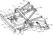
FIG. 2 is a schematic view of a rear body force transmitting structure according to an embodiment of the present utility model;
FIG. 3 is a schematic view of the structure of FIG. 2 from another perspective;
FIG. 4 is a schematic view of one of the side body rear side members, the rear shock tower, etc.;
FIG. 5 is a schematic view illustrating a structure of a rear shock tower according to an embodiment of the present utility model;
FIG. 6 is a schematic view of a rear-end collision force transmission structure of a vehicle according to an embodiment of the present utility model;
reference numerals illustrate:
1. a rear side member of the vehicle body; 2. a rear shock absorber; 3. a shock absorber beam; 4. reinforcing the support; 5. a passenger compartment; 6. a front connecting beam; 7. a rear connection beam; 8. a diagonal support beam; 9. a rear bumper beam; 10. a rear suspension mounting plate; 11. a front lower cross member; 12. a rear lower cross member; 13. reinforcing ribs; 14. b column; 15. a threshold beam; 16. a middle channel; 17. a rear wall reinforcing plate;
101. an upper longitudinal beam; 102. a side sill; 201. a rear shock absorber mounting groove; 202. a rear shock absorber mounting hole; 401. an inner stiffening beam; 402. an external reinforcing beam; 403. a connecting bracket; 501. a rear upper cross member; 502. a rear middle cross member; 503. a rear lower cross member; 1001. reinforcing rib plates.
Detailed Description
It should be noted that, without conflict, the embodiments of the present utility model and features of the embodiments may be combined with each other.
In the description of the present utility model, it should be noted that, if terms indicating an orientation or positional relationship such as "upper", "lower", "inner", "outer", etc. are presented, they are based on the orientation or positional relationship shown in the drawings, only for convenience of describing the present utility model and simplifying the description, and do not indicate or imply that the apparatus or element to be referred to must have a specific orientation, be constructed and operated in a specific orientation, and thus should not be construed as limiting the present utility model. Furthermore, the terms "first," "second," and the like, if any, are also used for descriptive purposes only and are not to be construed as indicating or implying relative importance.
In addition, in the description of the present utility model, unless otherwise specifically defined, the mating components may be connected using conventional connection structures in the art. Moreover, the terms "mounted," "connected," and "connected" are to be construed broadly. For example, the connection can be fixed connection, detachable connection or integrated connection; can be mechanically or electrically connected; can be directly connected or indirectly connected through an intermediate medium, and can be communication between two elements. The specific meaning of the above terms in the present utility model can be understood by those of ordinary skill in the art in combination with specific cases.
The utility model will be described in detail below with reference to the drawings in connection with embodiments.
Example 1
The present embodiment relates to a vehicle body rear force transmission structure, which is shown in conjunction with fig. 1 to 4, and includes vehicle body rear side members 1 provided separately on the left and right sides, rear shock towers 2 connected to the tops of the respective side vehicle body rear side members 1, and reinforcing brackets 4 provided on both sides of the rear shock towers 2 toward one side of the vehicle head.
Wherein, both sides reinforcing brackets 4 are "V" type to have interior stiffening beam 401 and outer stiffening beam 402, simultaneously, the front end of each interior stiffening beam 401 of side and outer stiffening beam 402 all links to each other with the back upper beam 501 that is located passenger cabin 5 rear portion, and the rear end of each interior stiffening beam 401 is connected at the top of the shock absorber tower 2 behind the homonymy, and the rear end of each outer stiffening beam 402 of side is connected at the lateral part of shock absorber tower 2 behind the homonymy, and in whole car upper and lower direction, the rear end of each outer stiffening beam 402 is less than the rear end setting of stiffening beam 401 in the homonymy.
At this time, by providing the reinforcing brackets 4 composed of the inner reinforcing beam 401 and the outer reinforcing beam 402 at the sides of the rear shock absorber 2 on both sides toward the vehicle head, and connecting the front ends of the inner reinforcing beam 401 and the outer reinforcing beam 402 with the rear upper cross member 501, the rear ends of the inner reinforcing beam 401 and the outer reinforcing beam 402 are connected with the rear shock absorber 2, and the rear ends of the outer reinforcing beam 402 are lower than the rear ends of the inner reinforcing beam 401. The present embodiment can not only improve the rigidity of the vehicle body rear portion position and the connection strength between the vehicle body rear portion and the passenger compartment 5 by means of the rear upper cross member 501, but also can form a force transmission passage between the vehicle body rear side member 1 and the rear upper cross member 501, thereby facilitating the transmission and dispersion of the collision force between the passenger compartment 5 and the vehicle body rear side member 1.
In addition, it can be understood that, in this embodiment, the inner reinforcement beam 401 and the outer reinforcement beam 402 in each reinforcement bracket 4 are different in height from one end connected to the rear shock absorber 2, and the inner reinforcement beam 401 connected to the top of the rear shock absorber 2 can also exert a pressing effect on the rear shock absorber 2, so as to help to improve the stability of the arrangement of the rear shock absorber 2.
Specifically, as a preferred embodiment, the vehicle body rear side members on each side of the present embodiment each include an upper side member 101 and a lower side member 102 arranged at an upper and lower interval, and at the same time, the rear end of the upper side member 101 is located rearward of the rear end of the lower side member 102 in the front-rear direction of the entire vehicle, that is, the upper side member 101 extends rearward of the vehicle by a length greater than that of the lower side member 102. In addition, the rear ends of the side upper stringers 101 are connected to the rear impact beam 9, and the front ends of the side upper stringers 101 are connected specifically to the rear center cross member 502 at the rear of the passenger compartment 5. The front ends of the side sills 102 are respectively connected with the rear ends of the side sill beams 15, the rear upper cross member 501 and the rear middle cross member 502 are also connected through the left and right side B pillars 14, a rear lower cross member 503 is further disposed below the rear middle cross member 502, and the rear lower cross member 503 is connected between the rear ends of the side sill beams 15.
It can be appreciated that the present embodiment enables the vehicle body rear side member 1 to be constituted by the upper side member 101 and the lower side member 102, and by providing the diagonal support beam 8 connected between the rear end of the lower side member 102 and the upper side member 102, it is possible to increase the structural strength of the vehicle body rear side member as a whole by the double-beam structure on the one hand, and the upper and lower side members can also form the up-down double-channel force transmission structure at the rear portion of the vehicle body, which contributes to the transmission dispersion of the rear collision force. On the other hand, the guiding action of the diagonal support beam 8 can be used to better transmit the collision force at the upper side member 101 to the lower side member 102, and the upper and lower side members can be used to transmit the collision force sufficiently, so that the collision force transmission effect at the rear part of the vehicle body can be improved.
In the present embodiment, the rear side member 1 is composed of the upper side member 101 and the lower side member 102, and each rear shock absorber 2 is connected to the top of the same side upper side member 101 as a preferred embodiment. In addition, in the embodiment, each rear shock absorber 2 is preferably made of an extruded aluminum profile, and each rear shock absorber 2 is provided with a rear shock absorber mounting groove 201, and each rear shock absorber mounting groove 201 is also provided with a rear shock absorber mounting point.
At this time, the rear shock absorber 2 is made of the extruded aluminum profile, so that the characteristics of simple preparation process, high structural strength and light weight of the extruded aluminum profile can be utilized, the rear shock absorber 2 can be conveniently prepared, the structural strength of the rear shock absorber 2 can be ensured, and the lightweight design of the rear shock absorber is facilitated.
In this embodiment, as shown in fig. 5, the rear shock absorber 2 made of extruded aluminum as described above is integrally of a square structure, and it may be attached to the top of the rear side member 1 of the vehicle body by a welding direction. Meanwhile, the rear damper mounting groove 201 may be formed in the rear shock absorber 2 in a machining direction after the rear shock absorber 2 is extrusion-formed.
Note that in machining the rear shock absorber mounting groove 201, a structure such as a mounting platform should be machined into the rear shock absorber mounting groove 201, and at this time, the rear shock absorber mounting point may be provided as a rear shock absorber mounting hole 202 located on the mounting platform as shown in fig. 5. The rear damper mounting holes 202 are specifically two arranged at intervals, and the openings face the notch of the rear damper mounting groove 201, which can mount the rear damper in the rear damper mounting groove 201 by bolts when it is specifically implemented.
In this embodiment, since the rear shock absorber 2 is provided on the top of the rear side member of the vehicle body, as a preferable embodiment, the triangular reinforcing ribs 13 are provided on the side of each rear shock absorber 2 facing the vehicle tail, that is, on the rear side of the rear shock absorber 2. The reinforcing ribs 13 at each rear shock absorber 2 may be generally provided in plural in a side-by-side arrangement, and each reinforcing rib 13 may be connected between the vehicle body rear side member 1 and the rear shock absorber 2. It will be appreciated that by providing the above-described triangular reinforcing ribs 13 between the rear shock absorber 2 and the vehicle body rear side member 1, it is possible to improve the reliability of the arrangement of the rear shock absorber 2 on the vehicle body rear side member 1, and thus the stability of the arrangement of the rear shock absorber.
As further shown in fig. 1 to 4, the present embodiment is also connected with a shock absorber cross member 3 between the rear shock absorber 2 on the left and right sides. At this time, through the setting of shock absorber crossbeam 3 between the shock absorber 2 behind both sides, help promoting the holistic torsional rigidity in automobile body rear portion, also can form the horizontal power transmission passageway between the shock absorber 2 behind both sides simultaneously, and do benefit to the transmission decomposition of collision power. The shock-absorbing tower beams 3 may be connected to the rear shock-absorbing towers 2 on both sides by conventional screw-coupling or welding, and preferably, the shock-absorbing tower beams 3 may be provided to be connected to the top of each rear shock-absorbing tower 2 so as to facilitate the connection therebetween.
In this embodiment, as a preferred embodiment, as further shown in fig. 1 and 2, the inner reinforcement beams 401 on both sides are also connected to the rear upper cross member 501 through the same connection bracket 403. Like this for stiffening beam 401 is connected with enclose entablature 501 after in both sides through same linking bridge 403, can make both sides reinforcing brace 4 form "W" type structure jointly, thereby can further improve the reinforcement effect of both sides reinforcing brace 4, also be convenient for strengthen the connection between support 4 and the enclose entablature 501 after simultaneously.
In particular, the connecting bracket 403 may be made of aluminum alloy plate and welded to the inner reinforcing beams 401 on both sides. In addition, as a preferred embodiment, the rear end of each outer reinforcement beam 402 of the present embodiment is specifically connected to the front end surface of the same-side rear shock absorber 2 facing the front of the vehicle. At this time, the outer reinforcing beam 402 connected to the front end surface of the rear shock absorber 2 can support the rear shock absorber 2 at the front side, and is helpful for improving the reliability of the arrangement of the rear shock absorber 2.
Further, based on the above arrangement of the reinforcing ribs 13 on the rear side of each rear shock absorber 2, it is apparent that the reinforcing ribs 13 on the same side and the outer reinforcing beam 402 can form a sandwich of the rear shock absorber 2 on the same side in the front-rear direction. Therefore, the stability of the rear shock absorber 2 can be better improved by utilizing the reinforcing ribs 13 on two sides and the external reinforcing beam 402, and the transmission effect of the rear collision force among the rear longitudinal beam 1 of the automobile body, the rear shock absorber 2 and the external reinforcing beam 402 can be better improved through the force transmission effect of each reinforcing rib 13.
As a preferred embodiment, the present embodiment is also provided with a connecting beam between the upper side member 101 and the lower side member 102 on both sides. The connecting beam is arranged between the upper longitudinal beam 101 and the lower longitudinal beam 102 to further connect the upper longitudinal beam and the lower longitudinal beam on the same side, so that on one hand, the connecting effect of the connecting beam can be utilized to further increase the overall strength of the rear longitudinal beam 1 of the vehicle body, and on the other hand, a force transmission channel can be formed between the upper longitudinal beam and the lower longitudinal beam through the arrangement of the connecting beam, the decomposition of collision force is facilitated, and the collision safety of the whole vehicle is improved.
In particular, as a preferred embodiment, as shown in fig. 1 to 4, the above-mentioned connecting beams provided between the upper and lower side members on both sides each include a front connecting beam 6 disposed near the front end of the rear side member 1 of the vehicle body, and the front connecting beam 6 is also provided obliquely from bottom to top to the rear side. Thus, by tilting the front connecting beam 6 from bottom to top to the rear side, downward guiding of the rear collision force can be achieved, facilitating the transfer of the collision force to the position of the rocker beams 15 below both sides of the passenger compartment 5, so as to reduce the intrusion injury to the passenger compartment 5.
Further, the connecting beam includes a rear connecting beam 7 connected to the rear end portion of the side sill 102. At this time, by providing the front connecting beam 6 and the rear connecting beam 7 at the same time, the present embodiment can reinforce the front and rear positions of the vehicle body rear side member 1, respectively, and can improve the overall torsional rigidity of the rear portion of the vehicle body.
In a specific design, each rear connecting beam 7 is arranged along the up-down direction of the whole vehicle, and the top end of each rear connecting beam 7 is connected with the upper longitudinal beam 101 on the same side. And, be connected the back end of longeron 102 with the longeron 101 through back tie-beam 7, it can be convenient for the connection setting of back tie-beam 7, also can make back tie-beam 7 play the effect of the crashproof roof beam of longeron 102 rear end to have bigger area of contact with the collision object between, and reach the effect that reduces the collision injury.
In this embodiment, on the basis of the rear connecting beam 7, as a preferred implementation manner, a diagonal support beam 8 is also provided on the rear side of the rear connecting beam 7 facing the rear of the vehicle, the diagonal support beam 8 is inclined from bottom to top toward the rear side, and the top end thereof is connected to an upper longitudinal beam 101 on the same side. In particular, the top ends of the rear connecting beams 7 on each side and the top ends of the side diagonal support beams 8 are also preferably connected to the bottom of the side members 101 on the same side. In this way, the top ends of the rear connecting beam 7 and the top ends of the diagonal support beams 8 are connected to the bottom of the upper longitudinal beam 101, so that the connection of the rear connecting beam 7 and the diagonal support beams 8 to the upper longitudinal beam 101 can be facilitated, and at the same time, it can be understood that the connection of the rear connecting beam 7 and the diagonal support beams 8 to the side portions of the upper longitudinal beam 101 can be avoided, and adverse effects are brought to the arrangement of peripheral components.
In addition, in the present embodiment, as shown in fig. 2 and 4, the bottom end of each side sill support 8 is preferably also disposed so as to be engaged with the rear end of the same side sill 102 in the front-rear direction of the entire vehicle. The engagement arrangement, that is, the projection of the bottom end of the diagonal support beam 8 and the rear end of the same-side sill 102 in the front-rear direction of the entire vehicle at least partially overlaps. By arranging the engagement between the bottom end of the diagonal brace 8 and the rear end of the same side sill 102, the continuity of the collision force transmission can be ensured, and the collision force transmission effect can be further improved.
The inner reinforcement beam 401, the outer reinforcement beam 402, the upper side member 101, the lower side member 102, the front connecting beam 6, the rear connecting beam 7, the diagonal support beam 8, and the like of the present embodiment may have a beam structure commonly used in the existing automobile body. Moreover, as a preferred embodiment, at least one of the inner reinforcement beam 401, the outer reinforcement beam 402, the upper side member 101, the lower side member 102, and the front connection beam 6, the rear connection beam 7, and the diagonal support beam 8 may be formed by using an extruded aluminum profile. Of course, it is preferable that each of the above beams is made of an extruded aluminum profile. The rear lower cross members described below are also preferably manufactured by extruding an aluminum profile.
In this embodiment, the beam bodies are made of extruded aluminum profiles, so that the characteristics of the extruded aluminum profiles can be utilized, the preparation of the beam bodies is facilitated, the structural strength of the beam bodies is ensured, and the weight reduction of the beam bodies is facilitated.
Still referring to fig. 4, as a preferred embodiment, the present embodiment is connected with a rear suspension mounting plate 10 between an upper side member 101 and a lower side member 102 on both sides, and is provided with rear suspension mounting points on the rear suspension mounting plate 10, and the above-described rear suspension mounting plates 10 are provided on both front and rear sides of the rear shock absorber 2. At this time, the rear suspension mounting plates 10 on each side of the rear shock absorber 2 are also generally provided in plural, and generally the rear suspension mounting plates 10 should be grouped in pairs, with two rear suspension mounting plates 10 of each group being arranged at intervals for mounting of each component in the rear suspension.
In particular, each rear suspension mounting plate 10 may preferably be made of an aluminum alloy plate and is connected to the upper side rail 101 and the lower side rail 102 by welding. The rear suspension mounting points on the rear suspension mounting plates 10 are usually achieved by using mounting holes formed in the rear suspension mounting plates 10, and in order to increase the reliability of the arrangement of the rear suspension mounting plates 10, reinforcing rib plates 1001 may preferably be provided at each rear suspension mounting plate 10 to achieve reinforcement of each rear suspension mounting plate 10. Each reinforcing plate 1001 may be made of an aluminum alloy plate.
It can be appreciated that by providing the rear suspension mounting plate 10 between the upper side member 101 and the lower side member 102, it is not only convenient for the mounting and arrangement of the rear suspension at the rear of the vehicle body, but also it is possible to increase the overall strength of the rear side member 1 of the vehicle body by using the rear suspension mounting plate 10 and to increase the collision force transmission path between the upper side member and the lower side member, thereby being beneficial to improving the collision safety of the whole vehicle.
As further shown in fig. 3, the present embodiment is also a preferred embodiment in which a rear lower cross member is further connected between the side sills 102, and specifically includes a front lower cross member 11 provided near the front ends of the side sills 102, and a rear lower cross member 12 connected between the rear ends of the side sills 102. The front lower cross member 11 and the rear lower cross member 12 may be connected between the side sills 102 on both sides by welding, and a connecting rib may be provided between each rear lower cross member and the side sills 102 to increase the connection reliability.
Through setting up each rear portion lower beam as above between both sides side sill 102, this embodiment can further improve the whole torsional rigidity in automobile body rear portion, and simultaneously, it also can make collision force transmit the decomposition better between both sides side sill 102, and can reduce the collision injury, promotes whole car collision security.
In this embodiment, as shown in fig. 6, when the automobile collides with the rear, the collision force is transmitted from the rear bumper beam 9 to the upper side member 101 of the rear side member 1, then a part of the collision force is transmitted along the upper side member 101 to the front center cross member 502 of the rear side member, and another part of the collision force is transmitted to the lower side member 102 under the guidance of the diagonal support beam 8, and then is transmitted along the lower side member 102 to the front side member 15.
For the collision force transferred along the upper stringers 101 on both sides, at each rear shock absorber 2, the collision force may be continuously transferred forward via the reinforcing brackets 4 on the same side, and the collision force transferred along the inner reinforcing beams 401 may be transferred to the middle channel 16 via the upper rear cross member 501 and the rear reinforcing plates 17, so as to be dispersed and absorbed by the middle channel 16 and the peripheral structure. The collision force transmitted along the outer reinforcement beam 402 is transmitted to the B pillar 14 through the rear upper cross member 501, and can be transmitted to the rocker beam 15 on the same side through the B pillar 14, so that the dispersion and absorption of the collision force can be performed through the rocker beam 15 and the peripheral structure.
Of course, when the vehicle collides with the front, the force of the front collision can be transmitted to each reinforcing bracket 4 through the center tunnel 16, the rear wall reinforcing plate 17, the rocker 15, the B pillar 14, the roof side rail, and the like on both sides, and can be transmitted to the rear side member 1 of the vehicle body and the like through the reinforcing brackets 4. According to the embodiment, the transmission and dispersion of the collision force by the force transmission channels formed by the force transmission structures can be realized, the collision force can be effectively dispersed and resolved, and the collision force is matched with the rear anti-collision beam 9 and the crumple energy absorption function of the vehicle body rear longitudinal beam 1 and the like, so that the collision safety of the whole vehicle can be well improved.
According to the vehicle body rear force transmission structure of the embodiment, the reinforcing brackets 4 formed by the inner reinforcing beams 401 and the outer reinforcing beams 402 are arranged on one sides, facing the vehicle head, of the rear shock absorber 2 on two sides, the front ends of the inner reinforcing beams 401 and the outer reinforcing beams 402 are connected with the rear surrounding upper cross beam 501, the rear ends of the inner reinforcing beams 401 and the outer reinforcing beams 402 are connected with the rear shock absorber 2, and the rear ends of the outer reinforcing beams 402 are lower than the rear ends of the inner reinforcing beams 401.
In this way, the present embodiment not only can improve the rigidity of the vehicle body rear portion position and the connection strength between the vehicle body rear portion and the passenger compartment 5 by means of the rear upper cross member 501, but also can form a force transmission passage between the vehicle body rear side member 1 and the rear upper cross member 501, which is helpful for the transmission and dispersion of the collision force between the passenger compartment 5 and the vehicle body rear side member. Meanwhile, the inner stiffening beam 401 can play a role in pressing down the rear shock absorber 2 by utilizing the different heights of the rear ends of the inner stiffening beam and the outer stiffening beam, the outer stiffening beam 402 plays a role in supporting the rear shock absorber 2, the stability of the rear shock absorber 2 is improved, the force transmission performance of the rear shock absorber 2 is improved, and the improvement of the collision safety of the whole vehicle is facilitated.
Example two
The present embodiment relates to an automobile in which the vehicle body is provided with the vehicle body rear force transmitting structure in the first embodiment.
The automobile of this embodiment can improve the rigidity of the rear position of the automobile body and the connection strength between the rear part of the automobile body and the passenger cabin 5 by arranging the rear force transmission structure of the automobile body in the first embodiment, and simultaneously can form a force transmission channel between the rear longitudinal beam 1 of the automobile body and the rear upper cross beam 5, thereby being beneficial to the transmission dispersion of collision force between the passenger cabin 5 and the rear longitudinal beam 1 of the automobile body, being beneficial to the improvement of the collision safety of the whole automobile and having good practicability.
The foregoing description of the preferred embodiments of the utility model is not intended to be limiting, but rather is intended to cover all modifications, equivalents, alternatives, and improvements that fall within the spirit and scope of the utility model.
Claims (10)
1. A car body rear portion biography power structure, its characterized in that:
the automobile body comprises automobile body rear longitudinal beams (1) which are respectively arranged at the left side and the right side, rear shock towers (2) which are connected to the tops of the automobile body rear longitudinal beams (1) at each side, and reinforcing brackets (4) which are respectively arranged at one side of the rear shock towers (2) facing the automobile head at both sides, wherein the reinforcing brackets (4) at both sides are V-shaped and are provided with inner reinforcing beams (401) and outer reinforcing beams (402);
each side inner reinforcement beam (401) with the front end of outer reinforcement beam (402) all links to each other with be located the back of passenger cabin (5) and enclose entablature (501), each side inner reinforcement beam (401)'s rear end is connected at the homonymy rear shock absorber (2) top, each side outer reinforcement beam (402)'s rear end is connected at the homonymy rear shock absorber (2) lateral part, and in whole car upper and lower direction, each outer reinforcement beam (402)'s rear end is less than homonymy inner reinforcement beam (401) rear end setting.
2. The vehicle body rear force transmitting structure according to claim 1, characterized in that:
the inner stiffening beams (401) on both sides are connected with the rear upper cross beam (501) through the same connecting bracket (403).
3. The vehicle body rear force transmitting structure according to claim 1, characterized in that:
the rear end of each external reinforcement beam (402) is connected to the end face of the rear shock absorber (2) on the same side, which faces the front side of the vehicle;
one side of each rear shock absorber (2) facing the tail is provided with a triangular reinforcing rib (13), and the reinforcing ribs (13) are connected between the vehicle body rear longitudinal beam (1) and the rear shock absorber (2).
4. The vehicle body rear force transmitting structure according to claim 1, characterized in that:
and a shock absorption tower cross beam (3) is connected between the rear shock absorption towers (2) at two sides.
5. A vehicle body rear force transmitting structure according to any one of claims 1 to 4, characterized in that:
the rear longitudinal beams (1) of the vehicle body on two sides comprise an upper longitudinal beam (101) and a lower longitudinal beam (102) which are arranged at intervals up and down, and each rear shock absorption tower (2) is connected to the top of the upper longitudinal beam (101) on the same side.
6. The vehicle body rear force transmitting structure according to claim 5, characterized in that:
connecting beams are connected between the upper longitudinal beam (101) and the lower longitudinal beam (102) at two sides;
the connecting beams on both sides comprise front connecting beams (6) which are arranged close to the front end of the rear longitudinal beam of the automobile body, and rear connecting beams (7) which are connected to the rear end parts of the lower longitudinal beams (102), and the top ends of the rear connecting beams (7) are connected to the upper longitudinal beam (101) on the same side.
7. The vehicle body rear force transmitting structure according to claim 6, characterized in that:
the front connecting beam (6) is obliquely arranged from bottom to top to one side of the tail; and/or each rear connecting beam (7) is arranged along the up-down direction of the whole vehicle, and the top end of each rear connecting beam (7) is connected to the bottom of the upper longitudinal beam (101) on the same side.
8. The vehicle body rear force transmitting structure according to claim 5, characterized in that:
a rear suspension mounting plate (10) is connected between the upper longitudinal beam (101) and the lower longitudinal beam (102) at two sides, a rear suspension mounting point is arranged on the rear suspension mounting plate (10), and the rear suspension mounting plate (10) is arranged at the front side and the rear side of the rear shock absorber (2); and/or the number of the groups of groups,
a rear lower cross beam is connected between the side sills (102) at both sides, and comprises a front lower cross beam (11) arranged close to the front ends of the side sills (102) at both sides and a rear lower cross beam (12) connected between the rear ends of the side sills (102) at both sides.
9. The vehicle body rear force transmitting structure according to claim 5, characterized in that:
the inner reinforcement beam (401), the outer reinforcement beam (402), and at least one of the upper longitudinal beam (101) and the lower longitudinal beam (102) are made of extruded aluminum profiles.
10. An automobile, characterized in that:
the vehicle is provided with the vehicle body rear force transmission structure according to any one of claims 1 to 9.
Priority Applications (1)
| Application Number | Priority Date | Filing Date | Title |
|---|---|---|---|
| CN202223393719.5U CN218907376U (en) | 2022-12-16 | 2022-12-16 | Automobile body rear part force transmission structure and automobile |
Applications Claiming Priority (1)
| Application Number | Priority Date | Filing Date | Title |
|---|---|---|---|
| CN202223393719.5U CN218907376U (en) | 2022-12-16 | 2022-12-16 | Automobile body rear part force transmission structure and automobile |
Publications (1)
| Publication Number | Publication Date |
|---|---|
| CN218907376U true CN218907376U (en) | 2023-04-25 |
Family
ID=86050847
Family Applications (1)
| Application Number | Title | Priority Date | Filing Date |
|---|---|---|---|
| CN202223393719.5U Active CN218907376U (en) | 2022-12-16 | 2022-12-16 | Automobile body rear part force transmission structure and automobile |
Country Status (1)
| Country | Link |
|---|---|
| CN (1) | CN218907376U (en) |
-
2022
- 2022-12-16 CN CN202223393719.5U patent/CN218907376U/en active Active
Similar Documents
| Publication | Publication Date | Title |
|---|---|---|
| CN109204496B (en) | Vehicle body structure and vehicle | |
| CN212797095U (en) | Vehicle body front structure and automobile | |
| CN215706639U (en) | Cabin front longitudinal beam rear end connecting structure and automobile | |
| CN111376986B (en) | Front structure of automobile body frame | |
| CN111547134A (en) | Vehicle, vehicle body and force transmission structure thereof | |
| CN211568102U (en) | Small-size electric motor car lower body frame | |
| CN210634630U (en) | Upper side beam force transmission structure | |
| CN218907376U (en) | Automobile body rear part force transmission structure and automobile | |
| CN112373576A (en) | Front floor assembly structure | |
| CN217496287U (en) | Vehicle rear floor structure and vehicle | |
| CN218907375U (en) | Rear collision force transmission structure of automobile body and automobile | |
| CN215883812U (en) | Front longitudinal beam of engine room and automobile | |
| CN218907388U (en) | Vehicle body rear structure and automobile | |
| CN214689769U (en) | Front end structure and vehicle | |
| CN114132383A (en) | Floor assembly for electric vehicle | |
| CN218858529U (en) | Car body rear portion truss structure and car | |
| CN219406615U (en) | Vehicle body front part force transmission structure and vehicle | |
| CN219728329U (en) | Vehicle body middle structure and vehicle | |
| CN220948190U (en) | Vehicle body structure and vehicle | |
| CN219406620U (en) | Front cabin structure and vehicle | |
| CN220948171U (en) | Vehicle body chassis structure and vehicle | |
| CN218858541U (en) | Backrest ring assembly and automobile | |
| CN218258400U (en) | Automobile front floor reinforcing structure and automobile | |
| CN219406616U (en) | Front structure of vehicle body and vehicle | |
| CN218858531U (en) | Automobile cabin structure and automobile |
Legal Events
| Date | Code | Title | Description |
|---|---|---|---|
| GR01 | Patent grant | ||
| GR01 | Patent grant |