EP4385824A1 - Vehicle and a display device for use therein - Google Patents
Vehicle and a display device for use therein Download PDFInfo
- Publication number
- EP4385824A1 EP4385824A1 EP22212881.1A EP22212881A EP4385824A1 EP 4385824 A1 EP4385824 A1 EP 4385824A1 EP 22212881 A EP22212881 A EP 22212881A EP 4385824 A1 EP4385824 A1 EP 4385824A1
- Authority
- EP
- European Patent Office
- Prior art keywords
- slide shoe
- guide rail
- slide
- curve
- display device
- Prior art date
- Legal status (The legal status is an assumption and is not a legal conclusion. Google has not performed a legal analysis and makes no representation as to the accuracy of the status listed.)
- Pending
Links
Images


Classifications
-
- B—PERFORMING OPERATIONS; TRANSPORTING
- B60—VEHICLES IN GENERAL
- B60K—ARRANGEMENT OR MOUNTING OF PROPULSION UNITS OR OF TRANSMISSIONS IN VEHICLES; ARRANGEMENT OR MOUNTING OF PLURAL DIVERSE PRIME-MOVERS IN VEHICLES; AUXILIARY DRIVES FOR VEHICLES; INSTRUMENTATION OR DASHBOARDS FOR VEHICLES; ARRANGEMENTS IN CONNECTION WITH COOLING, AIR INTAKE, GAS EXHAUST OR FUEL SUPPLY OF PROPULSION UNITS IN VEHICLES
- B60K35/00—Instruments specially adapted for vehicles; Arrangement of instruments in or on vehicles
- B60K35/50—Instruments characterised by their means of attachment to or integration in the vehicle
- B60K35/53—Movable instruments, e.g. slidable
-
- B—PERFORMING OPERATIONS; TRANSPORTING
- B60—VEHICLES IN GENERAL
- B60R—VEHICLES, VEHICLE FITTINGS, OR VEHICLE PARTS, NOT OTHERWISE PROVIDED FOR
- B60R11/00—Arrangements for holding or mounting articles, not otherwise provided for
- B60R11/02—Arrangements for holding or mounting articles, not otherwise provided for for radio sets, television sets, telephones, or the like; Arrangement of controls thereof
- B60R11/0229—Arrangements for holding or mounting articles, not otherwise provided for for radio sets, television sets, telephones, or the like; Arrangement of controls thereof for displays, e.g. cathodic tubes
- B60R11/0235—Arrangements for holding or mounting articles, not otherwise provided for for radio sets, television sets, telephones, or the like; Arrangement of controls thereof for displays, e.g. cathodic tubes of flat type, e.g. LCD
-
- B—PERFORMING OPERATIONS; TRANSPORTING
- B60—VEHICLES IN GENERAL
- B60R—VEHICLES, VEHICLE FITTINGS, OR VEHICLE PARTS, NOT OTHERWISE PROVIDED FOR
- B60R11/00—Arrangements for holding or mounting articles, not otherwise provided for
- B60R11/02—Arrangements for holding or mounting articles, not otherwise provided for for radio sets, television sets, telephones, or the like; Arrangement of controls thereof
- B60R11/0229—Arrangements for holding or mounting articles, not otherwise provided for for radio sets, television sets, telephones, or the like; Arrangement of controls thereof for displays, e.g. cathodic tubes
-
- B—PERFORMING OPERATIONS; TRANSPORTING
- B60—VEHICLES IN GENERAL
- B60K—ARRANGEMENT OR MOUNTING OF PROPULSION UNITS OR OF TRANSMISSIONS IN VEHICLES; ARRANGEMENT OR MOUNTING OF PLURAL DIVERSE PRIME-MOVERS IN VEHICLES; AUXILIARY DRIVES FOR VEHICLES; INSTRUMENTATION OR DASHBOARDS FOR VEHICLES; ARRANGEMENTS IN CONNECTION WITH COOLING, AIR INTAKE, GAS EXHAUST OR FUEL SUPPLY OF PROPULSION UNITS IN VEHICLES
- B60K35/00—Instruments specially adapted for vehicles; Arrangement of instruments in or on vehicles
- B60K35/20—Output arrangements, i.e. from vehicle to user, associated with vehicle functions or specially adapted therefor
- B60K35/21—Output arrangements, i.e. from vehicle to user, associated with vehicle functions or specially adapted therefor using visual output, e.g. blinking lights or matrix displays
- B60K35/22—Display screens
-
- B—PERFORMING OPERATIONS; TRANSPORTING
- B60—VEHICLES IN GENERAL
- B60K—ARRANGEMENT OR MOUNTING OF PROPULSION UNITS OR OF TRANSMISSIONS IN VEHICLES; ARRANGEMENT OR MOUNTING OF PLURAL DIVERSE PRIME-MOVERS IN VEHICLES; AUXILIARY DRIVES FOR VEHICLES; INSTRUMENTATION OR DASHBOARDS FOR VEHICLES; ARRANGEMENTS IN CONNECTION WITH COOLING, AIR INTAKE, GAS EXHAUST OR FUEL SUPPLY OF PROPULSION UNITS IN VEHICLES
- B60K35/00—Instruments specially adapted for vehicles; Arrangement of instruments in or on vehicles
- B60K35/55—Instruments with parts that can change their shape or position to configure an active screen, e.g. by folding or by rolling
-
- B—PERFORMING OPERATIONS; TRANSPORTING
- B60—VEHICLES IN GENERAL
- B60K—ARRANGEMENT OR MOUNTING OF PROPULSION UNITS OR OF TRANSMISSIONS IN VEHICLES; ARRANGEMENT OR MOUNTING OF PLURAL DIVERSE PRIME-MOVERS IN VEHICLES; AUXILIARY DRIVES FOR VEHICLES; INSTRUMENTATION OR DASHBOARDS FOR VEHICLES; ARRANGEMENTS IN CONNECTION WITH COOLING, AIR INTAKE, GAS EXHAUST OR FUEL SUPPLY OF PROPULSION UNITS IN VEHICLES
- B60K35/00—Instruments specially adapted for vehicles; Arrangement of instruments in or on vehicles
- B60K35/60—Instruments characterised by their location or relative disposition in or on vehicles
-
- H—ELECTRICITY
- H05—ELECTRIC TECHNIQUES NOT OTHERWISE PROVIDED FOR
- H05K—PRINTED CIRCUITS; CASINGS OR CONSTRUCTIONAL DETAILS OF ELECTRIC APPARATUS; MANUFACTURE OF ASSEMBLAGES OF ELECTRICAL COMPONENTS
- H05K5/00—Casings, cabinets or drawers for electric apparatus
- H05K5/02—Details
- H05K5/0217—Mechanical details of casings
-
- B—PERFORMING OPERATIONS; TRANSPORTING
- B60—VEHICLES IN GENERAL
- B60K—ARRANGEMENT OR MOUNTING OF PROPULSION UNITS OR OF TRANSMISSIONS IN VEHICLES; ARRANGEMENT OR MOUNTING OF PLURAL DIVERSE PRIME-MOVERS IN VEHICLES; AUXILIARY DRIVES FOR VEHICLES; INSTRUMENTATION OR DASHBOARDS FOR VEHICLES; ARRANGEMENTS IN CONNECTION WITH COOLING, AIR INTAKE, GAS EXHAUST OR FUEL SUPPLY OF PROPULSION UNITS IN VEHICLES
- B60K2360/00—Indexing scheme associated with groups B60K35/00 or B60K37/00 relating to details of instruments or dashboards
- B60K2360/60—Structural details of dashboards or instruments
- B60K2360/68—Features of instruments
- B60K2360/688—Frames or decorative parts
-
- B—PERFORMING OPERATIONS; TRANSPORTING
- B60—VEHICLES IN GENERAL
- B60K—ARRANGEMENT OR MOUNTING OF PROPULSION UNITS OR OF TRANSMISSIONS IN VEHICLES; ARRANGEMENT OR MOUNTING OF PLURAL DIVERSE PRIME-MOVERS IN VEHICLES; AUXILIARY DRIVES FOR VEHICLES; INSTRUMENTATION OR DASHBOARDS FOR VEHICLES; ARRANGEMENTS IN CONNECTION WITH COOLING, AIR INTAKE, GAS EXHAUST OR FUEL SUPPLY OF PROPULSION UNITS IN VEHICLES
- B60K2360/00—Indexing scheme associated with groups B60K35/00 or B60K37/00 relating to details of instruments or dashboards
- B60K2360/77—Instrument locations other than the dashboard
- B60K2360/771—Instrument locations other than the dashboard on the ceiling
-
- B—PERFORMING OPERATIONS; TRANSPORTING
- B60—VEHICLES IN GENERAL
- B60R—VEHICLES, VEHICLE FITTINGS, OR VEHICLE PARTS, NOT OTHERWISE PROVIDED FOR
- B60R11/00—Arrangements for holding or mounting articles, not otherwise provided for
- B60R2011/0001—Arrangements for holding or mounting articles, not otherwise provided for characterised by position
- B60R2011/0003—Arrangements for holding or mounting articles, not otherwise provided for characterised by position inside the vehicle
- B60R2011/0028—Ceiling, e.g. roof rails
-
- B—PERFORMING OPERATIONS; TRANSPORTING
- B60—VEHICLES IN GENERAL
- B60R—VEHICLES, VEHICLE FITTINGS, OR VEHICLE PARTS, NOT OTHERWISE PROVIDED FOR
- B60R11/00—Arrangements for holding or mounting articles, not otherwise provided for
- B60R2011/0042—Arrangements for holding or mounting articles, not otherwise provided for characterised by mounting means
- B60R2011/008—Adjustable or movable supports
- B60R2011/0082—Adjustable or movable supports collapsible, e.g. for storing after use
-
- B—PERFORMING OPERATIONS; TRANSPORTING
- B60—VEHICLES IN GENERAL
- B60R—VEHICLES, VEHICLE FITTINGS, OR VEHICLE PARTS, NOT OTHERWISE PROVIDED FOR
- B60R11/00—Arrangements for holding or mounting articles, not otherwise provided for
- B60R2011/0042—Arrangements for holding or mounting articles, not otherwise provided for characterised by mounting means
- B60R2011/008—Adjustable or movable supports
- B60R2011/0084—Adjustable or movable supports with adjustment by linear movement in their operational position
-
- B—PERFORMING OPERATIONS; TRANSPORTING
- B60—VEHICLES IN GENERAL
- B60R—VEHICLES, VEHICLE FITTINGS, OR VEHICLE PARTS, NOT OTHERWISE PROVIDED FOR
- B60R11/00—Arrangements for holding or mounting articles, not otherwise provided for
- B60R2011/0042—Arrangements for holding or mounting articles, not otherwise provided for characterised by mounting means
- B60R2011/008—Adjustable or movable supports
- B60R2011/0085—Adjustable or movable supports with adjustment by rotation in their operational position
-
- B—PERFORMING OPERATIONS; TRANSPORTING
- B60—VEHICLES IN GENERAL
- B60R—VEHICLES, VEHICLE FITTINGS, OR VEHICLE PARTS, NOT OTHERWISE PROVIDED FOR
- B60R11/00—Arrangements for holding or mounting articles, not otherwise provided for
- B60R2011/0042—Arrangements for holding or mounting articles, not otherwise provided for characterised by mounting means
- B60R2011/008—Adjustable or movable supports
- B60R2011/0092—Adjustable or movable supports with motorization
Definitions
- the invention relates to a display device according to the preamble of claim 1.
- Display devices in vehicles are known from the prior art for instance in which display devices are attached to the interior side of the roof of a vehicle and which displays can easily be pivoted from a storage position into an operational position in which the display screen is readable to the occupants of the vehicle.
- This display device only requires one drive motor which saves considerable cost.
- the lever is pivotally connected to the second slide shoe and preferably the screen support is connected such to the first and second slide shoes that, when moving between the operative position and the storage position, it is rotated and simultaneously slid at its upper end in a direction substantially parallel to the guide rail.
- the screen support may be pivotally connected at its upper end to one of the first and second slide shoes. The top of the display screen will then stay close to the roof when moving to the operational position.
- the lever may be pivotally connected to the screen support a distance from the upper end of the screen support. This distance will determine the transmission ratio between relative movement of the slide shoes and the angle of rotation of the screen support.
- the locking mechanism includes a locking element connected to the second slide shoe and to the first slide shoe, such that in a first position of the locking element, the first and second slide shoe are locked with respect to each other and in a second position of the locking element, the first slide shoe is free to move with respect to the second slide shoe.
- the second slide shoe is preferably locked with respect to guide rail by the locking element in the second position of the locking element.
- the locking element is a locking lever which is pivotally connected to the second slide shoe at a first end and is slidably in engagement with the first slide shoe, the locking lever being movably in engagement with the guide rail at its second end so as to rotate the locking lever between its first and second position.
- Such locking lever is a reliable locking element as a rotational movement is more reliable and wear resistant than a sliding/translational movement.
- the locking lever is provided with a pin on its second end which is in engagement with a curve in the guide rail, said curve including a first portion parallel to the longitudinal direction of the guide rail and a second portion angled with respect to the first portion
- the first slide shoe being provided with a pin which is slidably in engagement with a guide curve in the locking lever
- the guide curve of the locking lever including a first portion extending parallel to the longitudinal direction of the guide rail in its second position and including a second portion angled with respect the first portion of the guide curve, such that when the locking lever is in its second position the pin of the locking lever is in the second portion of the curve in the guide rail and the pin of the first slide shoe is in engagement with the first portion of the guide curve in the locking lever, and that when the locking lever is in its first position the pin of the locking lever is in the first portion of the curve in the guide rail and the pin of the first slide shoe is in engagement with the second portion of the guide curve in the locking lever.
- the curve of the guide rail may be formed in a locator mounted to the guide rail. This is much easier than working the curve directly into the guide rail.
- the invention also relates to a vehicle comprising the display device described above.
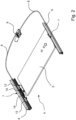
- Fig. 1 illustrates a vehicle, in this case a passenger car, having a compartment comprising front seats 1 and rear seats 2 for vehicle occupants, and a roof 3.
- a display device 4 is illustrated comprising a display screen 5 which is shown in an operational position with solid lines and in a storage position with dash lines.
- the operational position of the display screen 5 is the position in which the rear occupant has the optimum line of view on the display screen 5.
- a display device 4 is shown for the rear occupants. It is conceivable that the display device 4 is available for one or both occupants in the front of the vehicle.
- the display screen 5 In the storage position, the display screen 5 is positioned adjacent and parallel to the roof 3.
- Fig. 2 shows a perspective view of the display device 4 showing the display screen 5, two parallel guide rails 6 on either side of the display screen 5, an operating mechanism 7 supported and guided by each guide rail 6, drive cables 8 (guided in guide tubes) and a drive motor, here an electric motor 9.
- the guide rails 6 may be attached directly to the vehicle, such as the side beams of the roof 3, or a separate frame could be present, for example a frame of a roof system.
- the electric motor 9 can be actuated to move the operating mechanisms 7 through the drive cables 8 in order to displace the display screen 5 between the storage position and the operational position.
- the display screen 5 may be of such dimension that it extends along almost the complete width of the vehicle compartment, but smaller dimensions are conceivable of course. It would also be possible to mount two display screens side-by-side and being movable either independently (by 2 operating mechanisms) or together.
- Fig. 3 is an exploded view of one of the guide rails 6 and operating mechanisms 7.
- the operating mechanism 7 includes a screen support 10 to which the display screen 5 can be attached, for example by means of screws or bolts inserted through one or more holes 11 in the screen support 10 and into screw thread in the display screen 5.
- the screen support 10 is pivotally connected to a first slide shoe 12 and is connected to a second slide shoe 13 through a lever 14.
- the display support 10 has a vertical bracket 15 fixed to a pivot shaft 16 through a screw 17.
- the lever 14 is pivotally connected to the bracket 15 of the screen support 5 by a screw 18 and nut 19 ( Fig. 4 ), while the lever 14 is pivotally connected to the second slide shoe 13 by a screw 20 and pivot shaft 21.
- the slide shoes 12 and 13 are slidably guided in a groove 6A of the guide rail 6 and the first slide shoe 12 is fixed to an end of the respective drive cable 8 (not shown).
- the slide shoes 12 and '13 are positioned one after the other within the guide rail 6.
- Fig. 3 also shows a locking lever 22 which is pivotally connected to the second slide shoe 13 through a pivot pin 23 inserted in a hole 24 in the second slide shoe 13.
- the locking lever 22 comprises a curve 25 including a slide portion 25' substantially parallel to the guide rail 6 and a locking portion 25" angled to the slide portion 25' ( Fig. 5B ).
- a pin 26 on the first slide shoe 12 (only a hole for the pin 26 is shown in Fig. 3 ) engages the curve 25.
- the locking lever 22 is provided with a pin 27 near its end remote from the pivot pin 23 and therefore close to the locking portion 25'' of the curve 25.
- a locator 28 is fixed to the guide rail 6 and comprises a curve 29 comprising a sliding portion 29' extending parallel to the guide rail 6 and a locking portion 29'' angled to the longitudinal extent of the guide rail 6 ( Fig. 5B ).
- the locator 28 is positioned in and fixed to the guide rail 6 in a position deeper into the guide rail 6 than the groove 6a so that the slide shoes 12 and 13, and the locking lever 22 do not interfere with the locator 28.
- One end of the locking lever 22 is positioned adjacent to the locator 28 such that the pin 27 engages into the curve 29.
- Fig. 4 shows how the slide shoe 12, locking lever 22 and locator 28 are positioned within the guide rail 6.
- the slide shoes 12, 13 are firmly held at their upper and lower sides by the groove 6A of the guide rail 6.
- a cable guide 6B in the guide rail 6 through which the drive cable 8 runs.
- a cable attachment (not shown) will fix the cable 8 to the first slide shoe 12.
- Figs. 5 - 7 illustrate the operation of the operating mechanism 7 for the display screen 5.
- Figs. 5A and 5b show the position of the operating mechanism 7 when the display screen 5/display support 10 is in its storage position.
- the slide shoes 12 and 13 are locked to each other by the locking lever 22 because the pin 26 of the first slide shoe 12 is located in the locking portion 25'' of the curve 25 in the locking lever 22.
- the pin 26 cannot move out of the locking portion 25'' because the pin 27 of the locking lever 22 is located in the sliding portion 29' of the curve 29 in the locator 28 so that a vertical movement, i.e. a rotation of the locking lever 22 around pivot pin 23 is prevented thereby.
- the first slide shoe 12 is driven by the cable 8 to the right in Figs. 5a and 5B , both slide shoes 12, 13 will be moved in common, and thus the display screen 10 will be moved parallel to the guide rail 6.
- the lever 22 is locked with respect to the guide rail 6 because the pin 27 of the lever 22 is locked in the upper end of the locking portion 29'' in the curve 29 of the locator 28 in the guide rail 6 due to the pin 26 being present in the horizontally oriented sliding portion 25' of the curve 25 in the locking lever 22.
- Figs. 7A and 7B show the operating mechanism 7 in a position in which the display screen 5 on the screen support 10 is in its operational position, i.e. directed vertically or almost vertically. It is clear from a comparison of Figs. 6 and 7 that the first slide shoe 12 is moved toward the second slide shoe 13 which is locked to the guide rail 6 due to the lever 22 being locked to the locator 28. In Fig. 7B , the pin 26 of the first slide shoe 12 has arrived at the end of the sliding portion 25' of the curve 25 in the lever 22. No further movement is possible.
- the drive motor 9 is drawn at the right side in Fig. 2 but could also be positioned on the other side. It would also be possible to drive the second slide shoe 13 and lock and unlock the first slide shoe.
- the display screen 5 then make a pure rotational movement when moving between the position parallel to the guide rails 6 and the vertical or inclined operational position.
- the locking lever or other locking element could not only move in vertical direction with respect to the guide rail, but also in lateral direction.
- the curve 25 of the locking lever 22 could also be formed in the second slide shoe 13 engaged by a pin of the locking lever 22.
- the curve 29 of the locator 29 in the guide rail 6 will then be in the locking lever 22 engaged by a pin 27 in the guide rail 6 or locator 28.
- the length of the locator 28 and the sliding portion 29' of its curve 29 may be varied depending on the desired length of the horizontal movement of the display screen 5 before it is rotated to its operational position.
- the first and second slide shoes 12, 13 are here guided in the same groove 6A of the guide rail, but it is conceivable that they are guided in different grooves of the guide rail 6.
- the display devices 7 can be of any type available on the market. Normally, the display screen 5 will be faced up in its storage position, but it is of course also conceivable that a two-sided screen is used which is for example useful if the front seats are rotatable, such as in a mobile home or autonomous vehicle.
Landscapes
- Engineering & Computer Science (AREA)
- Mechanical Engineering (AREA)
- Chemical & Material Sciences (AREA)
- Combustion & Propulsion (AREA)
- Transportation (AREA)
- Microelectronics & Electronic Packaging (AREA)
- Fittings On The Vehicle Exterior For Carrying Loads, And Devices For Holding Or Mounting Articles (AREA)
- Devices For Indicating Variable Information By Combining Individual Elements (AREA)
Abstract
Description
- The invention relates to a display device according to the preamble of
claim 1. - Display devices in vehicles are known from the prior art for instance in which display devices are attached to the interior side of the roof of a vehicle and which displays can easily be pivoted from a storage position into an operational position in which the display screen is readable to the occupants of the vehicle.
- It is one of the objects of the present invention to provide for a display device which has a simplified operating mechanism.
- The object is achieved in a display device having the features of the characterizing portion of
claim 1. - This display device only requires one drive motor which saves considerable cost.
- In one embodiment, the lever is pivotally connected to the second slide shoe and preferably the screen support is connected such to the first and second slide shoes that, when moving between the operative position and the storage position, it is rotated and simultaneously slid at its upper end in a direction substantially parallel to the guide rail.
- The screen support may be pivotally connected at its upper end to one of the first and second slide shoes. The top of the display screen will then stay close to the roof when moving to the operational position.
- The lever may be pivotally connected to the screen support a distance from the upper end of the screen support. This distance will determine the transmission ratio between relative movement of the slide shoes and the angle of rotation of the screen support.
- The locking mechanism includes a locking element connected to the second slide shoe and to the first slide shoe, such that in a first position of the locking element, the first and second slide shoe are locked with respect to each other and in a second position of the locking element, the first slide shoe is free to move with respect to the second slide shoe.
- The second slide shoe is preferably locked with respect to guide rail by the locking element in the second position of the locking element.
- In a preferred embodiment, the locking element is a locking lever which is pivotally connected to the second slide shoe at a first end and is slidably in engagement with the first slide shoe, the locking lever being movably in engagement with the guide rail at its second end so as to rotate the locking lever between its first and second position.
- Such locking lever is a reliable locking element as a rotational movement is more reliable and wear resistant than a sliding/translational movement.
- In a further development, the locking lever is provided with a pin on its second end which is in engagement with a curve in the guide rail, said curve including a first portion parallel to the longitudinal direction of the guide rail and a second portion angled with respect to the first portion, the first slide shoe being provided with a pin which is slidably in engagement with a guide curve in the locking lever, the guide curve of the locking lever including a first portion extending parallel to the longitudinal direction of the guide rail in its second position and including a second portion angled with respect the first portion of the guide curve, such that when the locking lever is in its second position the pin of the locking lever is in the second portion of the curve in the guide rail and the pin of the first slide shoe is in engagement with the first portion of the guide curve in the locking lever, and that when the locking lever is in its first position the pin of the locking lever is in the first portion of the curve in the guide rail and the pin of the first slide shoe is in engagement with the second portion of the guide curve in the locking lever.
- The curve of the guide rail may be formed in a locator mounted to the guide rail. This is much easier than working the curve directly into the guide rail.
- The invention also relates to a vehicle comprising the display device described above.
- The invention will be further explained with reference to the drawings showing exemplary embodiments of the roof construction and vehicle according to the invention.
-
Fig. 1 is a very schematic side view, partially broken away, of a vehicle with a display device. -
Fig. 2 is an enlarged perspective view of the display device ofFig. 1 . -
Figs. 3 is a further enlarged exploded view of a guide rail and operating mechanism of the display device ofFig. 2 . -
Fig. 4 is a further enlarged view in the direction of arrow IV inFig. 2 . -
Figs. 5A ,6A and7A are perspective views of the operating mechanism ofFig. 3 in 3 different positions. -
Figs. 5B ,6B and7B are side views of the locking mechanism of the operating mechanism ofFigs. 5A ,6A and7A in the same positions. -
Fig. 1 illustrates a vehicle, in this case a passenger car, having a compartment comprisingfront seats 1 andrear seats 2 for vehicle occupants, and aroof 3. Further adisplay device 4 is illustrated comprising adisplay screen 5 which is shown in an operational position with solid lines and in a storage position with dash lines. The operational position of thedisplay screen 5 is the position in which the rear occupant has the optimum line of view on thedisplay screen 5. InFig. 1 adisplay device 4 is shown for the rear occupants. It is conceivable that thedisplay device 4 is available for one or both occupants in the front of the vehicle. In the storage position, thedisplay screen 5 is positioned adjacent and parallel to theroof 3. -
Fig. 2 shows a perspective view of thedisplay device 4 showing thedisplay screen 5, twoparallel guide rails 6 on either side of thedisplay screen 5, anoperating mechanism 7 supported and guided by eachguide rail 6, drive cables 8 (guided in guide tubes) and a drive motor, here anelectric motor 9. Theguide rails 6 may be attached directly to the vehicle, such as the side beams of theroof 3, or a separate frame could be present, for example a frame of a roof system. Theelectric motor 9 can be actuated to move theoperating mechanisms 7 through thedrive cables 8 in order to displace thedisplay screen 5 between the storage position and the operational position. Thedisplay screen 5 may be of such dimension that it extends along almost the complete width of the vehicle compartment, but smaller dimensions are conceivable of course. It would also be possible to mount two display screens side-by-side and being movable either independently (by 2 operating mechanisms) or together. -
Fig. 3 is an exploded view of one of theguide rails 6 andoperating mechanisms 7. Theoperating mechanism 7 includes ascreen support 10 to which thedisplay screen 5 can be attached, for example by means of screws or bolts inserted through one ormore holes 11 in thescreen support 10 and into screw thread in thedisplay screen 5. - The
screen support 10 is pivotally connected to afirst slide shoe 12 and is connected to asecond slide shoe 13 through alever 14. In this case, thedisplay support 10 has avertical bracket 15 fixed to apivot shaft 16 through ascrew 17. Thelever 14 is pivotally connected to thebracket 15 of thescreen support 5 by ascrew 18 and nut 19 (Fig. 4 ), while thelever 14 is pivotally connected to thesecond slide shoe 13 by ascrew 20 andpivot shaft 21. Theslide shoes groove 6A of theguide rail 6 and thefirst slide shoe 12 is fixed to an end of the respective drive cable 8 (not shown). Theslide shoes 12 and '13 are positioned one after the other within theguide rail 6. -
Fig. 3 also shows alocking lever 22 which is pivotally connected to thesecond slide shoe 13 through apivot pin 23 inserted in ahole 24 in thesecond slide shoe 13. Thelocking lever 22 comprises acurve 25 including a slide portion 25' substantially parallel to theguide rail 6 and alocking portion 25" angled to the slide portion 25' (Fig. 5B ). Apin 26 on the first slide shoe 12 (only a hole for thepin 26 is shown inFig. 3 ) engages thecurve 25. Thelocking lever 22 is provided with apin 27 near its end remote from thepivot pin 23 and therefore close to the locking portion 25'' of thecurve 25. - A
locator 28 is fixed to theguide rail 6 and comprises acurve 29 comprising a sliding portion 29' extending parallel to theguide rail 6 and a locking portion 29'' angled to the longitudinal extent of the guide rail 6 (Fig. 5B ). Thelocator 28 is positioned in and fixed to theguide rail 6 in a position deeper into theguide rail 6 than thegroove 6a so that theslide shoes locking lever 22 do not interfere with thelocator 28. One end of thelocking lever 22 is positioned adjacent to thelocator 28 such that thepin 27 engages into thecurve 29. -
Fig. 4 shows how theslide shoe 12,locking lever 22 andlocator 28 are positioned within theguide rail 6. Theslide shoes groove 6A of theguide rail 6. Also shown is acable guide 6B in theguide rail 6 through which thedrive cable 8 runs. A cable attachment (not shown) will fix thecable 8 to thefirst slide shoe 12. -
Figs. 5 - 7 illustrate the operation of theoperating mechanism 7 for thedisplay screen 5. -
Figs. 5A and 5b show the position of theoperating mechanism 7 when thedisplay screen 5/display support 10 is in its storage position. Theslide shoes locking lever 22 because thepin 26 of thefirst slide shoe 12 is located in the locking portion 25'' of thecurve 25 in thelocking lever 22. Thepin 26 cannot move out of the locking portion 25'' because thepin 27 of thelocking lever 22 is located in the sliding portion 29' of thecurve 29 in thelocator 28 so that a vertical movement, i.e. a rotation of thelocking lever 22 aroundpivot pin 23 is prevented thereby. Thus, if in this position, thefirst slide shoe 12 is driven by thecable 8 to the right inFigs. 5a and 5B , both slideshoes display screen 10 will be moved parallel to theguide rail 6. - In
Figs. 6A and 6B , thepin 27 of thelever 22 has arrived at the locking portion 29'' of thecurve 29 and thepin 27 is forced to move in upward direction along the locking portion 29'', thereby rotating thelever 22 inFig. 6 in an anti-clockwise direction, whereby the locking portion 25'' of thecurve 25 moving upwards with respect to thepin 26. In this manner, thepin 26 arrives in the sliding portion 25' of thecurve 25 as is shown inFig. 6B . Thepin 26 is now free to move through the sliding portion 25' of thecurve 25 in thelever 22, which now extends parallel to thegroove 6A in theguide rail 6. Thelever 22 is locked with respect to theguide rail 6 because thepin 27 of thelever 22 is locked in the upper end of the locking portion 29'' in thecurve 29 of thelocator 28 in theguide rail 6 due to thepin 26 being present in the horizontally oriented sliding portion 25' of thecurve 25 in the lockinglever 22. -
Figs. 7A and 7B show theoperating mechanism 7 in a position in which thedisplay screen 5 on thescreen support 10 is in its operational position, i.e. directed vertically or almost vertically. It is clear from a comparison ofFigs. 6 and7 that thefirst slide shoe 12 is moved toward thesecond slide shoe 13 which is locked to theguide rail 6 due to thelever 22 being locked to thelocator 28. InFig. 7B , thepin 26 of thefirst slide shoe 12 has arrived at the end of the sliding portion 25' of thecurve 25 in thelever 22. No further movement is possible. During the travel of thefirst slide shoe 12 with respect to thesecond slide shoe 13, the upper side of thescreen support 10 and of thedisplay screen 5 has been slid, while thescreen support 10 anddisplay screen 5 have also been rotated due to the downward rotation of thelever 14 which resulted from the relative movements of the first and second slide shoes 12, 13 decreasing the length of the base of the triangle formed by thelever 14, thescreen support 10 and the slide shoes 12, 13. This deformable triangle leads to the desired movements of thedisplay screen 5. - An actuation of the
drive motor 9 in the reverse direction results in an opposite movement of thescreen support 10 anddisplay screen 5 toward the storage position again. - The invention is not limited to the example described above and shown in the drawings and may be varied in different other ways. For instance, the
drive motor 9 is drawn at the right side inFig. 2 but could also be positioned on the other side. It would also be possible to drive thesecond slide shoe 13 and lock and unlock the first slide shoe. Thedisplay screen 5 then make a pure rotational movement when moving between the position parallel to theguide rails 6 and the vertical or inclined operational position. The locking lever or other locking element could not only move in vertical direction with respect to the guide rail, but also in lateral direction. Thecurve 25 of the lockinglever 22 could also be formed in thesecond slide shoe 13 engaged by a pin of the lockinglever 22. Thecurve 29 of thelocator 29 in theguide rail 6 will then be in the lockinglever 22 engaged by apin 27 in theguide rail 6 orlocator 28. The length of thelocator 28 and the sliding portion 29' of itscurve 29 may be varied depending on the desired length of the horizontal movement of thedisplay screen 5 before it is rotated to its operational position. The first and second slide shoes 12, 13 are here guided in thesame groove 6A of the guide rail, but it is conceivable that they are guided in different grooves of theguide rail 6. Thedisplay devices 7 can be of any type available on the market. Normally, thedisplay screen 5 will be faced up in its storage position, but it is of course also conceivable that a two-sided screen is used which is for example useful if the front seats are rotatable, such as in a mobile home or autonomous vehicle.
Claims (11)
- Display device (4) for attachment to a roof of a vehicle, comprising:at least one display screen (5) capable of showing images to occupants in the vehicle, andan operating mechanism (7) mounted to the roof construction for moving the display screen (5) at least into a storage position and into an operational position in which the display screen (5) is visible for occupants in an interior space of the vehicle, the operating mechanism (7) including:at least one guide rail (6) to be mounted to the roof of the vehicle,a first (12) and second (13) slide shoe slidably guided in the guide rail (6) one after the other, at least the first slide shoe (12) being driven by a drive motor (9),a screen support (10) for supporting the display screen (5), said screen support being pivotally connected to one of the first and second slide shoes (12, 13), and a lever (14) pivotally connected to the screen support and to the other of the first and second slide shoes (13, 12) to move, i.e. at least rotate, the display screen between its operational position and storage position by changing the distance between the first and second slide shoes (12, 13),characterized in that only the first slide shoe (12) is driven by the electric motor (9), the second slide shoe (13) being provided with a locking mechanism ((22 - 29), configured to lock the second slide shoe (13) at a position where the display screen (5) is moved toward its operational position.
- Display device according to claim 1, wherein the lever is pivotally connected to the second slide shoe.
- Display device according to claim 2, wherein the screen support is connected such to the first and second slide shoes that, when moving between the operative position and the storage position, it is rotated and simultaneously slid at its upper end in a direction substantially parallel to the guide rail.
- Display device according to claim 1, wherein the screen support is pivotally connected at its upper end to one of the first and second slide shoes.
- Display device according to claim 4, wherein the lever is pivotally connected to the screen support a distance from the upper end of the screen support.
- Display device according to claim 1, wherein the locking mechanism includes a locking element connected to the second slide shoe and to the first slide shoe, such that in a first position of the locking element, the first and second slide shoe are locked with respect to each other and in a second position of the locking element, the first slide shoe is free to move with respect to the second slide shoe.
- Display device according to claim 6, wherein the second slide shoe is locked with respect to guide rail by the locking element in the second position of the locking element.
- Display device according to claim 7, wherein the locking element is a locking lever which is pivotally connected to the second slide shoe at a first end and is slidably in engagement with the first slide shoe, the locking lever being movably in engagement with the guide rail at its second end so as to rotate the locking lever between its first and second position.
- Display device according to claim 8, wherein the locking lever is provided with a pin on its second end which is in engagement with a curve in the guide rail, said curve including a first portion parallel to the longitudinal direction of the guide rail and a second portion angled with respect to the first portion, the first slide shoe being provided with a pin which is slidably in engagement with a guide curve in the locking lever, the guide curve of the locking lever including a first portion extending parallel to the longitudinal direction of the guide rail in its second position and including a second portion angled with respect the first portion of the guide curve, such that when the locking lever is in its second position the pin of the locking lever is in the second portion of the curve in the guide rail and the pin of the first slide shoe is in engagement with the first portion of the guide curve in the locking lever, and that when the locking lever is in its first position the pin of the locking lever is in the first portion of the curve in the guide rail and the pin of the first slide shoe is in engagement with the second portion of the guide curve in the locking lever.
- Display device according to claim 9, wherein the curve of the guide rail is formed in a locator mounted to the guide rail.
- Vehicle, comprising the display device according to any of the preceding claims.
Priority Applications (4)
| Application Number | Priority Date | Filing Date | Title |
|---|---|---|---|
| EP22212881.1A EP4385824A1 (en) | 2022-12-12 | 2022-12-12 | Vehicle and a display device for use therein |
| CN202311660747.5A CN118182339A (en) | 2022-12-12 | 2023-12-06 | Vehicle and display device therefor |
| KR1020230176221A KR20240087584A (en) | 2022-12-12 | 2023-12-07 | Vehicle and a display device for use therein |
| US18/534,533 US20240190250A1 (en) | 2022-12-12 | 2023-12-08 | Vehicle and a display device for use therein |
Applications Claiming Priority (1)
| Application Number | Priority Date | Filing Date | Title |
|---|---|---|---|
| EP22212881.1A EP4385824A1 (en) | 2022-12-12 | 2022-12-12 | Vehicle and a display device for use therein |
Publications (1)
| Publication Number | Publication Date |
|---|---|
| EP4385824A1 true EP4385824A1 (en) | 2024-06-19 |
Family
ID=84820315
Family Applications (1)
| Application Number | Title | Priority Date | Filing Date |
|---|---|---|---|
| EP22212881.1A Pending EP4385824A1 (en) | 2022-12-12 | 2022-12-12 | Vehicle and a display device for use therein |
Country Status (4)
| Country | Link |
|---|---|
| US (1) | US20240190250A1 (en) |
| EP (1) | EP4385824A1 (en) |
| KR (1) | KR20240087584A (en) |
| CN (1) | CN118182339A (en) |
Cited By (1)
| Publication number | Priority date | Publication date | Assignee | Title |
|---|---|---|---|---|
| EP4659984A1 (en) * | 2024-06-05 | 2025-12-10 | Yanfeng International Automotive Technology Co., Ltd. | Display device for vehicle interior and vehicle including same |
Families Citing this family (1)
| Publication number | Priority date | Publication date | Assignee | Title |
|---|---|---|---|---|
| DE102023118830B3 (en) * | 2023-07-17 | 2024-12-05 | Webasto SE | Device for adjusting a display arrangement for a vehicle roof and vehicle roof for a motor vehicle |
Citations (6)
| Publication number | Priority date | Publication date | Assignee | Title |
|---|---|---|---|---|
| WO2020020763A1 (en) * | 2018-07-27 | 2020-01-30 | Bayerische Motoren Werke Aktiengesellschaft | Display device, and vehicle |
| DE102018129479A1 (en) * | 2018-11-22 | 2020-05-28 | Webasto SE | Device and method for setting a display arrangement for a vehicle roof and vehicle roof for a motor vehicle |
| EP3683097A1 (en) * | 2019-01-21 | 2020-07-22 | Webasto SE | Device and method for adjusting a display assembly for a vehicle roof and corresponding roof |
| US20200290442A1 (en) * | 2019-03-15 | 2020-09-17 | Webasto SE | Apparatus and method for adjusting a screen arrangement for a vehicle roof, and vehicle roof for a motor vehicle |
| DE102019124081B3 (en) * | 2019-09-09 | 2021-02-11 | Webasto SE | Device and method for securing a screen arrangement for a vehicle roof and vehicle roof for a motor vehicle |
| EP3845420A1 (en) * | 2019-12-30 | 2021-07-07 | Inalfa Roof Systems Group B.V. | Vehicle and roof construction including a display device for use therein |
-
2022
- 2022-12-12 EP EP22212881.1A patent/EP4385824A1/en active Pending
-
2023
- 2023-12-06 CN CN202311660747.5A patent/CN118182339A/en active Pending
- 2023-12-07 KR KR1020230176221A patent/KR20240087584A/en active Pending
- 2023-12-08 US US18/534,533 patent/US20240190250A1/en active Pending
Patent Citations (6)
| Publication number | Priority date | Publication date | Assignee | Title |
|---|---|---|---|---|
| WO2020020763A1 (en) * | 2018-07-27 | 2020-01-30 | Bayerische Motoren Werke Aktiengesellschaft | Display device, and vehicle |
| DE102018129479A1 (en) * | 2018-11-22 | 2020-05-28 | Webasto SE | Device and method for setting a display arrangement for a vehicle roof and vehicle roof for a motor vehicle |
| EP3683097A1 (en) * | 2019-01-21 | 2020-07-22 | Webasto SE | Device and method for adjusting a display assembly for a vehicle roof and corresponding roof |
| US20200290442A1 (en) * | 2019-03-15 | 2020-09-17 | Webasto SE | Apparatus and method for adjusting a screen arrangement for a vehicle roof, and vehicle roof for a motor vehicle |
| DE102019124081B3 (en) * | 2019-09-09 | 2021-02-11 | Webasto SE | Device and method for securing a screen arrangement for a vehicle roof and vehicle roof for a motor vehicle |
| EP3845420A1 (en) * | 2019-12-30 | 2021-07-07 | Inalfa Roof Systems Group B.V. | Vehicle and roof construction including a display device for use therein |
Cited By (1)
| Publication number | Priority date | Publication date | Assignee | Title |
|---|---|---|---|---|
| EP4659984A1 (en) * | 2024-06-05 | 2025-12-10 | Yanfeng International Automotive Technology Co., Ltd. | Display device for vehicle interior and vehicle including same |
Also Published As
| Publication number | Publication date |
|---|---|
| KR20240087584A (en) | 2024-06-19 |
| US20240190250A1 (en) | 2024-06-13 |
| CN118182339A (en) | 2024-06-14 |
Similar Documents
| Publication | Publication Date | Title |
|---|---|---|
| EP4385824A1 (en) | Vehicle and a display device for use therein | |
| US4923250A (en) | Headrest apparatus | |
| US11458908B2 (en) | Display device and vehicle | |
| KR100273867B1 (en) | Layout structure of automotive display | |
| US9132788B2 (en) | Display device in a motor vehicle | |
| CN111204292B (en) | Device and method for adjusting a display assembly and roof for a motor vehicle | |
| JP4392611B2 (en) | Seat slide device | |
| US4913489A (en) | Device for varying the distance between the seats in commercial aircraft | |
| US6986493B2 (en) | Slide device for automotive seat | |
| US11577662B2 (en) | Device and method for securing a display screen arrangement for a vehicle roof, and vehicle roof for a motor vehicle | |
| EP4008590B1 (en) | Vehicle and roof construction including a display device for use therein | |
| US20180326823A1 (en) | Drive system for a movable roof part of a spoiler roof module of a motor vehicle | |
| US6857613B2 (en) | Slide device for automotive seat | |
| US20160107514A1 (en) | Drive system for a movable roof part of a motor vehicle roof module | |
| DE102006022861B4 (en) | Overhead mountable sliding structure for a video display and process | |
| KR20210034603A (en) | Adjustable assembly for vehicles with rotatable table elements | |
| CN115009177A (en) | Screen adjusting device and electronic equipment | |
| EP3659865B1 (en) | System for removably fixing a vehicle rooftop box | |
| US20030218368A1 (en) | Seat lifting devices | |
| RU2580588C1 (en) | Gear lever system | |
| CN218198258U (en) | Driver platform with screen upset switching mechanism | |
| CN114906068B (en) | Well accuse screen sliding structure and vehicle | |
| JP2008195239A (en) | Sun visor device for vehicle | |
| KR102880820B1 (en) | Long slide type rail system for vehicle seat | |
| DE102005048070B4 (en) | Entertainment device for a motor vehicle |
Legal Events
| Date | Code | Title | Description |
|---|---|---|---|
| PUAI | Public reference made under article 153(3) epc to a published international application that has entered the european phase |
Free format text: ORIGINAL CODE: 0009012 |
|
| STAA | Information on the status of an ep patent application or granted ep patent |
Free format text: STATUS: THE APPLICATION HAS BEEN PUBLISHED |
|
| AK | Designated contracting states |
Kind code of ref document: A1 Designated state(s): AL AT BE BG CH CY CZ DE DK EE ES FI FR GB GR HR HU IE IS IT LI LT LU LV MC ME MK MT NL NO PL PT RO RS SE SI SK SM TR |
|
| STAA | Information on the status of an ep patent application or granted ep patent |
Free format text: STATUS: REQUEST FOR EXAMINATION WAS MADE |
|
| 17P | Request for examination filed |
Effective date: 20241218 |
|
| STAA | Information on the status of an ep patent application or granted ep patent |
Free format text: STATUS: EXAMINATION IS IN PROGRESS |
|
| 17Q | First examination report despatched |
Effective date: 20251008 |