EP4385794A1 - Braking method for a vehicle and electro-mechanical braking system - Google Patents
Braking method for a vehicle and electro-mechanical braking system Download PDFInfo
- Publication number
- EP4385794A1 EP4385794A1 EP23216500.1A EP23216500A EP4385794A1 EP 4385794 A1 EP4385794 A1 EP 4385794A1 EP 23216500 A EP23216500 A EP 23216500A EP 4385794 A1 EP4385794 A1 EP 4385794A1
- Authority
- EP
- European Patent Office
- Prior art keywords
- braking
- electro
- mechanical
- brake
- friction
- Prior art date
- Legal status (The legal status is an assumption and is not a legal conclusion. Google has not performed a legal analysis and makes no representation as to the accuracy of the status listed.)
- Pending
Links
Images


Classifications
-
- B—PERFORMING OPERATIONS; TRANSPORTING
- B60—VEHICLES IN GENERAL
- B60L—PROPULSION OF ELECTRICALLY-PROPELLED VEHICLES; SUPPLYING ELECTRIC POWER FOR AUXILIARY EQUIPMENT OF ELECTRICALLY-PROPELLED VEHICLES; ELECTRODYNAMIC BRAKE SYSTEMS FOR VEHICLES IN GENERAL; MAGNETIC SUSPENSION OR LEVITATION FOR VEHICLES; MONITORING OPERATING VARIABLES OF ELECTRICALLY-PROPELLED VEHICLES; ELECTRIC SAFETY DEVICES FOR ELECTRICALLY-PROPELLED VEHICLES
- B60L7/00—Electrodynamic brake systems for vehicles in general
- B60L7/24—Electrodynamic brake systems for vehicles in general with additional mechanical or electromagnetic braking
- B60L7/26—Controlling the braking effect
-
- F—MECHANICAL ENGINEERING; LIGHTING; HEATING; WEAPONS; BLASTING
- F16—ENGINEERING ELEMENTS AND UNITS; GENERAL MEASURES FOR PRODUCING AND MAINTAINING EFFECTIVE FUNCTIONING OF MACHINES OR INSTALLATIONS; THERMAL INSULATION IN GENERAL
- F16D—COUPLINGS FOR TRANSMITTING ROTATION; CLUTCHES; BRAKES
- F16D55/00—Brakes with substantially-radial braking surfaces pressed together in axial direction, e.g. disc brakes
- F16D55/02—Brakes with substantially-radial braking surfaces pressed together in axial direction, e.g. disc brakes with axially-movable discs or pads pressed against axially-located rotating members
-
- B—PERFORMING OPERATIONS; TRANSPORTING
- B60—VEHICLES IN GENERAL
- B60L—PROPULSION OF ELECTRICALLY-PROPELLED VEHICLES; SUPPLYING ELECTRIC POWER FOR AUXILIARY EQUIPMENT OF ELECTRICALLY-PROPELLED VEHICLES; ELECTRODYNAMIC BRAKE SYSTEMS FOR VEHICLES IN GENERAL; MAGNETIC SUSPENSION OR LEVITATION FOR VEHICLES; MONITORING OPERATING VARIABLES OF ELECTRICALLY-PROPELLED VEHICLES; ELECTRIC SAFETY DEVICES FOR ELECTRICALLY-PROPELLED VEHICLES
- B60L7/00—Electrodynamic brake systems for vehicles in general
- B60L7/24—Electrodynamic brake systems for vehicles in general with additional mechanical or electromagnetic braking
-
- B—PERFORMING OPERATIONS; TRANSPORTING
- B60—VEHICLES IN GENERAL
- B60L—PROPULSION OF ELECTRICALLY-PROPELLED VEHICLES; SUPPLYING ELECTRIC POWER FOR AUXILIARY EQUIPMENT OF ELECTRICALLY-PROPELLED VEHICLES; ELECTRODYNAMIC BRAKE SYSTEMS FOR VEHICLES IN GENERAL; MAGNETIC SUSPENSION OR LEVITATION FOR VEHICLES; MONITORING OPERATING VARIABLES OF ELECTRICALLY-PROPELLED VEHICLES; ELECTRIC SAFETY DEVICES FOR ELECTRICALLY-PROPELLED VEHICLES
- B60L15/00—Methods, circuits, or devices for controlling the traction-motor speed of electrically-propelled vehicles
- B60L15/20—Methods, circuits, or devices for controlling the traction-motor speed of electrically-propelled vehicles for control of the vehicle or its driving motor to achieve a desired performance, e.g. speed, torque, programmed variation of speed
- B60L15/2009—Methods, circuits, or devices for controlling the traction-motor speed of electrically-propelled vehicles for control of the vehicle or its driving motor to achieve a desired performance, e.g. speed, torque, programmed variation of speed for braking
-
- B—PERFORMING OPERATIONS; TRANSPORTING
- B60—VEHICLES IN GENERAL
- B60L—PROPULSION OF ELECTRICALLY-PROPELLED VEHICLES; SUPPLYING ELECTRIC POWER FOR AUXILIARY EQUIPMENT OF ELECTRICALLY-PROPELLED VEHICLES; ELECTRODYNAMIC BRAKE SYSTEMS FOR VEHICLES IN GENERAL; MAGNETIC SUSPENSION OR LEVITATION FOR VEHICLES; MONITORING OPERATING VARIABLES OF ELECTRICALLY-PROPELLED VEHICLES; ELECTRIC SAFETY DEVICES FOR ELECTRICALLY-PROPELLED VEHICLES
- B60L7/00—Electrodynamic brake systems for vehicles in general
- B60L7/10—Dynamic electric regenerative braking
-
- B—PERFORMING OPERATIONS; TRANSPORTING
- B60—VEHICLES IN GENERAL
- B60T—VEHICLE BRAKE CONTROL SYSTEMS OR PARTS THEREOF; BRAKE CONTROL SYSTEMS OR PARTS THEREOF, IN GENERAL; ARRANGEMENT OF BRAKING ELEMENTS ON VEHICLES IN GENERAL; PORTABLE DEVICES FOR PREVENTING UNWANTED MOVEMENT OF VEHICLES; VEHICLE MODIFICATIONS TO FACILITATE COOLING OF BRAKES
- B60T13/00—Transmitting braking action from initiating means to ultimate brake actuator with power assistance or drive; Brake systems incorporating such transmitting means, e.g. air-pressure brake systems
- B60T13/74—Transmitting braking action from initiating means to ultimate brake actuator with power assistance or drive; Brake systems incorporating such transmitting means, e.g. air-pressure brake systems with electrical assistance or drive
- B60T13/741—Transmitting braking action from initiating means to ultimate brake actuator with power assistance or drive; Brake systems incorporating such transmitting means, e.g. air-pressure brake systems with electrical assistance or drive acting on an ultimate actuator
-
- B—PERFORMING OPERATIONS; TRANSPORTING
- B60—VEHICLES IN GENERAL
- B60T—VEHICLE BRAKE CONTROL SYSTEMS OR PARTS THEREOF; BRAKE CONTROL SYSTEMS OR PARTS THEREOF, IN GENERAL; ARRANGEMENT OF BRAKING ELEMENTS ON VEHICLES IN GENERAL; PORTABLE DEVICES FOR PREVENTING UNWANTED MOVEMENT OF VEHICLES; VEHICLE MODIFICATIONS TO FACILITATE COOLING OF BRAKES
- B60T13/00—Transmitting braking action from initiating means to ultimate brake actuator with power assistance or drive; Brake systems incorporating such transmitting means, e.g. air-pressure brake systems
- B60T13/74—Transmitting braking action from initiating means to ultimate brake actuator with power assistance or drive; Brake systems incorporating such transmitting means, e.g. air-pressure brake systems with electrical assistance or drive
- B60T13/746—Transmitting braking action from initiating means to ultimate brake actuator with power assistance or drive; Brake systems incorporating such transmitting means, e.g. air-pressure brake systems with electrical assistance or drive and mechanical transmission of the braking action
-
- F—MECHANICAL ENGINEERING; LIGHTING; HEATING; WEAPONS; BLASTING
- F16—ENGINEERING ELEMENTS AND UNITS; GENERAL MEASURES FOR PRODUCING AND MAINTAINING EFFECTIVE FUNCTIONING OF MACHINES OR INSTALLATIONS; THERMAL INSULATION IN GENERAL
- F16D—COUPLINGS FOR TRANSMITTING ROTATION; CLUTCHES; BRAKES
- F16D55/00—Brakes with substantially-radial braking surfaces pressed together in axial direction, e.g. disc brakes
- F16D55/02—Brakes with substantially-radial braking surfaces pressed together in axial direction, e.g. disc brakes with axially-movable discs or pads pressed against axially-located rotating members
- F16D55/22—Brakes with substantially-radial braking surfaces pressed together in axial direction, e.g. disc brakes with axially-movable discs or pads pressed against axially-located rotating members by clamping an axially-located rotating disc between movable braking members, e.g. movable brake discs or brake pads
- F16D55/224—Brakes with substantially-radial braking surfaces pressed together in axial direction, e.g. disc brakes with axially-movable discs or pads pressed against axially-located rotating members by clamping an axially-located rotating disc between movable braking members, e.g. movable brake discs or brake pads with a common actuating member for the braking members
- F16D55/225—Brakes with substantially-radial braking surfaces pressed together in axial direction, e.g. disc brakes with axially-movable discs or pads pressed against axially-located rotating members by clamping an axially-located rotating disc between movable braking members, e.g. movable brake discs or brake pads with a common actuating member for the braking members the braking members being brake pads
- F16D55/226—Brakes with substantially-radial braking surfaces pressed together in axial direction, e.g. disc brakes with axially-movable discs or pads pressed against axially-located rotating members by clamping an axially-located rotating disc between movable braking members, e.g. movable brake discs or brake pads with a common actuating member for the braking members the braking members being brake pads in which the common actuating member is moved axially, e.g. floating caliper disc brakes
-
- B—PERFORMING OPERATIONS; TRANSPORTING
- B60—VEHICLES IN GENERAL
- B60L—PROPULSION OF ELECTRICALLY-PROPELLED VEHICLES; SUPPLYING ELECTRIC POWER FOR AUXILIARY EQUIPMENT OF ELECTRICALLY-PROPELLED VEHICLES; ELECTRODYNAMIC BRAKE SYSTEMS FOR VEHICLES IN GENERAL; MAGNETIC SUSPENSION OR LEVITATION FOR VEHICLES; MONITORING OPERATING VARIABLES OF ELECTRICALLY-PROPELLED VEHICLES; ELECTRIC SAFETY DEVICES FOR ELECTRICALLY-PROPELLED VEHICLES
- B60L2240/00—Control parameters of input or output; Target parameters
- B60L2240/40—Drive Train control parameters
- B60L2240/42—Drive Train control parameters related to electric machines
- B60L2240/423—Torque
-
- B—PERFORMING OPERATIONS; TRANSPORTING
- B60—VEHICLES IN GENERAL
- B60L—PROPULSION OF ELECTRICALLY-PROPELLED VEHICLES; SUPPLYING ELECTRIC POWER FOR AUXILIARY EQUIPMENT OF ELECTRICALLY-PROPELLED VEHICLES; ELECTRODYNAMIC BRAKE SYSTEMS FOR VEHICLES IN GENERAL; MAGNETIC SUSPENSION OR LEVITATION FOR VEHICLES; MONITORING OPERATING VARIABLES OF ELECTRICALLY-PROPELLED VEHICLES; ELECTRIC SAFETY DEVICES FOR ELECTRICALLY-PROPELLED VEHICLES
- B60L2250/00—Driver interactions
- B60L2250/26—Driver interactions by pedal actuation
-
- B—PERFORMING OPERATIONS; TRANSPORTING
- B60—VEHICLES IN GENERAL
- B60L—PROPULSION OF ELECTRICALLY-PROPELLED VEHICLES; SUPPLYING ELECTRIC POWER FOR AUXILIARY EQUIPMENT OF ELECTRICALLY-PROPELLED VEHICLES; ELECTRODYNAMIC BRAKE SYSTEMS FOR VEHICLES IN GENERAL; MAGNETIC SUSPENSION OR LEVITATION FOR VEHICLES; MONITORING OPERATING VARIABLES OF ELECTRICALLY-PROPELLED VEHICLES; ELECTRIC SAFETY DEVICES FOR ELECTRICALLY-PROPELLED VEHICLES
- B60L7/00—Electrodynamic brake systems for vehicles in general
-
- B—PERFORMING OPERATIONS; TRANSPORTING
- B60—VEHICLES IN GENERAL
- B60T—VEHICLE BRAKE CONTROL SYSTEMS OR PARTS THEREOF; BRAKE CONTROL SYSTEMS OR PARTS THEREOF, IN GENERAL; ARRANGEMENT OF BRAKING ELEMENTS ON VEHICLES IN GENERAL; PORTABLE DEVICES FOR PREVENTING UNWANTED MOVEMENT OF VEHICLES; VEHICLE MODIFICATIONS TO FACILITATE COOLING OF BRAKES
- B60T2201/00—Particular use of vehicle brake systems; Special systems using also the brakes; Special software modules within the brake system controller
- B60T2201/12—Pre-actuation of braking systems without significant braking effect; Optimizing brake performance by reduction of play between brake pads and brake disc
-
- B—PERFORMING OPERATIONS; TRANSPORTING
- B60—VEHICLES IN GENERAL
- B60T—VEHICLE BRAKE CONTROL SYSTEMS OR PARTS THEREOF; BRAKE CONTROL SYSTEMS OR PARTS THEREOF, IN GENERAL; ARRANGEMENT OF BRAKING ELEMENTS ON VEHICLES IN GENERAL; PORTABLE DEVICES FOR PREVENTING UNWANTED MOVEMENT OF VEHICLES; VEHICLE MODIFICATIONS TO FACILITATE COOLING OF BRAKES
- B60T2270/00—Further aspects of brake control systems not otherwise provided for
- B60T2270/60—Regenerative braking
- B60T2270/604—Merging friction therewith; Adjusting their repartition
-
- F—MECHANICAL ENGINEERING; LIGHTING; HEATING; WEAPONS; BLASTING
- F16—ENGINEERING ELEMENTS AND UNITS; GENERAL MEASURES FOR PRODUCING AND MAINTAINING EFFECTIVE FUNCTIONING OF MACHINES OR INSTALLATIONS; THERMAL INSULATION IN GENERAL
- F16D—COUPLINGS FOR TRANSMITTING ROTATION; CLUTCHES; BRAKES
- F16D2121/00—Type of actuator operation force
- F16D2121/18—Electric or magnetic
- F16D2121/24—Electric or magnetic using motors
Definitions
- the present application relates to braking technology, and more particularly to electro-mechanical braking technology.
- Chinese patent publication No. CN110103926A discloses a braking system. If an electric braking force is not required, when difference between a maximum regenerative braking force and an actual regenerative braking force is below a set difference, a piston of an electric braking device is moved to a waiting position to reduce a gap between a friction member and a rotating body; and when the difference between the two is greater than the set difference, the piston is in a retracted position with a greater gap.
- the technical effect that this publication intends to achieve is to reduce the gap and ensure good responsiveness when the possibility of producing the electric braking force increases.
- the action of clearance reduction should be performed when there is no electric braking requirement, so as to achieve the effect of rapid response.
- the clearance reduction is only performed when the actual regenerative braking force is close to the maximum regenerative braking force.
- the present invention provides a braking method and a braking system capable of shortening the response time of a friction braking system.
- the present invention can shorten the response time, and improve safety and brake smoothness.
- a braking method for a vehicle performed by an electro-mechanical braking system includes an electro-mechanical braking system and a regenerative braking system.
- the electro-mechanical braking system includes at least one axle control unit, and a plurality of electro-mechanical braking devices provided at ends of wheels and driven by motors to apply friction braking forces to the wheels, and in response to a braking requirement, the electro-mechanical braking devices are controlled by the axle control unit to switch between a state in which friction braking is not applied and a state in which the friction braking is applied.
- the method includes: setting a brake clearance between a brake pad and a brake disc of each of the electro-mechanical braking devices to an initial value; determining whether there is a braking requirement; determining whether regenerative braking is produced by a drive motor of the regenerative braking system; and in response to producing of the regenerative braking, controlling the electro-mechanical braking device to move the brake pad, such that the brake clearance is at a preset value, wherein the preset value is smaller than the initial value.
- an electro-mechanical braking system includes at least one axle control unit, and a plurality of electro-mechanical braking devices provided at ends of wheels and driven by motors to apply friction braking forces to the wheels, the electro-mechanical braking devices are controlled by the axle control unit to switch between a state in which friction braking is not applied and a state in which the friction braking is applied in response to a braking requirement; a memory in communication connection with the at least one axle control unit, wherein the memory stores thereon machine-executable instructions; and a processor in communication connection with the at least one axle control unit, and the memory, wherein the machine-executable instructions, when executed by the processor, cause the electro-mechanical braking system to perform the steps of the method described according to the first aspect of the present disclosure.
- the friction braking system for a vehicle is realized by an Electro-Mechanical Braking (EMB) system.
- EMB Electro-Mechanical Braking
- the electro-mechanical braking device is controlled by the electro-mechanical braking system to reduce the brake clearance, such that the friction braking system can quickly get involved when friction braking is required.
- the response time of the vehicle to the friction braking requirement is shortened, so that the connection and switch between the friction braking and the regenerative braking is smoother, and the comfort during braking is effectively improved.
- modules/components referenced with the same/similar reference numbers across the various figures generally refer to the same modules/components.
- a composite braking system composed of a friction braking system providing friction braking and a regenerative braking system providing regenerative (electric feedback) braking is often used as a braking system for the vehicle.
- a drive motor is switched to an engine for operation and a rotor of the drive motor is driven to rotate by inertia of the vehicle, so that a reverse torque is produced, and a part of kinetic energy or potential energy is converted into electric energy for recovery, meanwhile a braking force is provided to the vehicle.
- the friction braking system In the friction braking system, a mechanical transmission mechanism is driven to, for example, push a brake pad to rub against a brake disc, so that a braking force is produced.
- the friction braking system in the composite braking system is realized by an Electro-Mechanical Braking (EMB) system.
- EMB Electro-Mechanical Braking
- electric energy is directly used as power source, and the electric energy is converted into a friction braking force acting on wheels through a brake motor and a mechanical transmission mechanism to apply service brake and parking brake. It is a pure drive-by-wire braking system with the characteristics of high energy efficiency, rapid response, and environmental friendliness, and can be well adapted to assisted driving and unmanned driving systems.
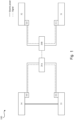
- Fig. 1 illustrates a schematic architectural diagram of an electro-mechanical braking system 100 according to some aspects of the present disclosure.
- the electro-mechanical braking system 100 includes two axle control units 20A and 20B, and a plurality of electro-mechanical braking devices 311, 321, 331, and 341 provided at ends of wheels and driven by motors to apply friction braking forces to the wheels 31, 32, 33, and 34.
- Axle control units 20A and 20B are provided corresponding to two axles of the vehicle, and each axle control unit controls and/or supplies power to the electro-mechanical braking devices 311, 321, 331, and 341 provided at both ends of the corresponding axle.
- the axle control unit 20A or 20B may be mounted on the vehicle as a separately packaged device. However, it would have occurred to a person of ordinary skill in the art that internal elements can also be mounted at different positions of the vehicle in a non-independent packaging manner, and packaging manner and mounting position can be adjusted according to actual layout of the vehicle as long as the control and/or power supply for the electro-mechanical braking device can be realized.
- the electro-mechanical braking devices 311, 321, 331, and 341 provided at the ends of wheels of the vehicle to provide braking forces to the wheels each include a brake motor 230 for producing a braking force, and a mechanical transmission mechanism driven by the brake motor 230.
- a brake motor 230 for producing a braking force
- a mechanical transmission mechanism driven by the brake motor 230 Taking a disc brake as an example, through the brake motor 230, electrical power is converted to mechanical power to drive the mechanical transmission mechanism to push the brake pad 238 toward or away from the brake disc 239, so that a friction braking force is produced or removed.
- the electro-mechanical braking devices 311, 321, 331, and 341 each include a brake motor controller 237 that controls rotation amount of the brake motor 230 to produce the required braking force based on the braking force requirement sent by the axle control unit 20A or 20B.
- the axle control unit 20A or 20B may control the electro-mechanical braking devices 311, 321, 331, and 341 to switch between a state in which the friction braking force is not applied and a state in which the friction braking force is applied in response to the braking requirement.
- the electro-mechanical braking devices 311, 321, 331, and 341 may further each include a sensor (not shown) configured to detect the state of the electro-mechanical braking device.
- the sensor may include a braking force sensor configured to detect amount of the braking force applied by the electro-mechanical braking device, such as by a pressure sensor that detects the pressure between a brake pad and a brake disc.
- the sensor may include a motor voltage sensor and a motor current sensor configured to detect a voltage and a current produced by the brake motor.
- the sensor may include a motor rotational position sensor configured to detect rotational position and rotation amount of the brake motor.
- the electro-mechanical braking devices 311, 321, 331, and 341 may each include one or more of a braking force sensor, a motor voltage sensor, a motor current sensor, a motor rotational position sensor, and/or any other type of sensors.
- the electro-mechanical braking system 100 may further include a memory (not shown), having machine-executable instructions stored thereon, in communication connection with at least one axle control unit 20A or 20B; and a processor in communication connection with at least one axle control unit 20A or 20B, and the memory.
- the machine-executable instructions when executed by the processor, cause the electro-mechanical braking system 100 to perform various operations.
- the electro-mechanical braking system 100 as shown in Fig. 1 may be implemented in a vehicle that is partially or fully powered by a drive motor.
- the electro-mechanical braking system 100 may be implemented in a battery electric vehicle or a hybrid vehicle where a drive motor is used as power source.
- the vehicle may further include a drive motor controller for controlling the motor.
- the drive motor controller may be implemented as an independent module.
- the drive motor controller may be integrated into the axle control unit in the electro-mechanical braking system 100 or into a vehicle control unit (VCU) of the vehicle.
- the vehicle may further include a drive system controller for controlling a drive system of the vehicle, and a wheel speed sensor for detecting wheel speed.
- a wheel speed sensor may be arranged in correspondence with each of the wheels 31, 32, 33, and 34 of the vehicle to monitor wheel speed so as to provide vehicle reference speed, vehicle longitudinal acceleration, and other information.
- the vehicle may further include a brake pedal for inputting a braking requirement and/or an accelerator pedal for inputting an acceleration requirement.
- braking information and/or acceleration information may include pedal stepping depth information and/or pedal stepping speed information.
- the electro-mechanical braking system 100 may be in communication connection with one or more of a drive motor controller, a drive system controller of a vehicle, a vehicle control unit (VCU), a wheel speed sensor, a brake pedal, and/or an accelerator pedal.
- VCU vehicle control unit
- a braking system for the vehicle may include a friction braking system providing a friction braking force and a regenerative braking system providing a regenerative braking force.
- the friction braking system may be implemented by the electro-mechanical braking system 100 as shown in Fig. 1 .
- the system 200 may include a braking system 201 for the vehicle.
- the vehicle braking system 201 may include an electro-mechanical braking system 202 that provides a friction braking force.
- an electro-mechanical braking system 202 may be an example of the electro-mechanical braking system 100 as shown in Fig. 1 .
- the electro-mechanical braking system 202 may include at least one axle control unit 20A or 20B, and electro-mechanical braking devices 311, 321, 331, and 341.
- the electro-mechanical braking devices 311, 321, 331, and 341 may each include a brake motor 230, and a mechanical transmission mechanism 231.
- the electro-mechanical braking devices 311, 321, 331, and 341 each include a brake motor controller 237, and may each include a braking force sensor 212, a motor voltage sensor 213, a motor current sensor 214, a motor rotational position sensor 215, and/or other sensors 216.
- the braking system 201 for the vehicle further includes a regenerative braking system 203.
- the regenerative braking system 203 includes a drive motor 220 and a drive motor controller 221.
- the drive motor 220 is switched to an engine for operation and a rotor of the drive motor is driven to rotate by inertia of the vehicle, so that a reverse torque is produced, and a part of the kinetic energy or potential energy is converted into electric energy for recovery, whereby a regenerative braking force is provided to the vehicle.
- the drive motor controller 221 may be integrated into the axle control unit 20A or 20B in the electro-mechanical braking system 202 or a vehicle control unit (VCU) 302 in the system 200.
- VCU vehicle control unit
- the system 200 may further include a vehicle drive system controller 301, a vehicle control unit (VCU) 302, a wheel speed sensor 303, and a brake pedal and/or an accelerator pedal 304.
- the axle control unit 20A or 20B is communication connection with electro-mechanical braking devices 311, 321, 331, and 341 (including the optional braking force sensor 212, motor voltage sensor 213, motor current sensor 214, motor rotational position sensor 215, and/or other sensors 216, and brake motor controllers).
- the axle control unit 20A or 20B is communication connection with a drive motor controller 221, a vehicle drive system controller 301, a vehicle control unit (VCU) 302, a wheel speed sensor 303, and a brake pedal and/or an accelerator pedal 304.
- the braking system for the vehicle determines a total braking force required by the vehicle based on various factors such as current vehicle speed, depth and speed at which the user steps on the pedal, etc. If the required total braking force is small, it may be provided completely by the regenerative braking system, i.e. the electro-mechanical braking system is not required to produce a friction braking force. If the total braking force required by the vehicle exceeds an available maximum regenerative braking force, the total braking force required by the vehicle is required to be provided by both the regenerative braking force and the friction braking force. In the configuration shown in Fig.
- the total braking force required by the vehicle may be provided by both the friction braking force provided by the electro-mechanical braking system 202 and the regenerative braking force provided by the regenerative braking system 203.
- distribution of the total braking force between the regenerative braking force and the friction braking force is dynamically changed.
- electrical power is converted to mechanical power to drive the mechanical transmission mechanism to push the brake pad 238 toward or away from the brake disc 239 to produce the required braking force.
- the axle control unit 20A or 20B of the electro-mechanical braking system 202 controls rotation amount of the brake motor to push the brake pads 238 of the electro-mechanical braking devices 311, 321, 331, and 341 to rub against the brake disc 239, so that a braking force is produced and thus a friction braking force is provided to the vehicle. As shown in Figs.
- a braking method 400 is described below in conjunction with Figs. 2 to 4 .
- the method 400 may be performed, for example, by the electro-mechanical braking system 100 or 202 described with reference to Figs. 1 and 2 providing a friction braking force.
- the method 400 may include: step 420, acquiring regenerative braking information.
- step 420 may include obtaining regenerative braking information by the axle control unit 20A or 20B from one or more of the drive motor controller 221, the vehicle drive system controller 301, and the vehicle control unit 302.
- the regenerative braking information may include information on whether a regenerative braking force was applied and/or information on magnitude of the regenerative braking force.
- the method for determining whether a regenerative braking force was applied includes: (1) the wheels are driven to move by the drive motors, the drive motor shaft is subjected to a positive torque from the drive motor and a negative torque from the wheels, and when regenerative braking is performed, the drive motor stops producing a driving force for movement, and the motor shaft is driven in a positive direction by inertia of the wheels; and therefore, torques in opposite directions are received by the motor shaft before and after the regenerative braking, and once direction of the torque received by the drive motor shaft is measured to change from a negative direction to a positive direction by the torque sensor, it means that the regenerative braking is performed; and (2) when a drive power supply is turned off, the drive power supply neither output current nor produce electromotive force, the motor shaft is driven to rotate by inertia of the wheels, so that regenerative current and electromotive force are produced, and once the regenerative current and electromotive force are measured by an ammeter or an electromotive force sensor, it means that the
- the method 400 may include: step 440, in response to the regenerative braking force being applied to the wheels, controlling, by the axle control unit 20A or 20B, rotation amount of the brake motor 230 to drive the mechanical transmission mechanism 231 to operate until the brake clearance C between the brake pad 238 and the brake disc 239 reaches a preset value, which is smaller than an initial value of the brake clearance when braking is not required.
- the preset value of the brake clearance C is in a range of 0 ⁇ C ⁇ 0.1 mm.
- This position may be determined by the braking force sensor 212, the motor voltage sensor 213, the motor current sensor 214, the motor rotational position sensor 215, and/or other sensors 216 as shown in Fig. 2 .
- the braking force sensor such as a pressure sensor, is used to detect the pressure between the brake pad and the brake disc. When the brake pad is not in contact with the brake disc, no signal is output by the pressure sensor. When the brake pad is in contact with the brake disc, the pressure sensor outputs a pressure signal.
- the electro-mechanical braking device is driven to the position of slight contact.
- the signals output by the motor voltage sensor 213, the motor current sensor 214, and the motor rotational position sensor 215 may be referred to for checking to improve accuracy of position confirmation.
- the method 400 may optionally include, prior to step 420: step 410, determining whether braking is required.
- step 410 may include determining, by the axle control unit 20A or 20B, the total braking force required by the vehicle based on various factors such as braking information and/or acceleration information obtained from the brake pedal and/or accelerator pedal 304, the current vehicle speed obtained from the wheel speed sensor 303, etc.
- determining whether braking is required may include determining, by the axle control unit 20A or 20B, distribution of the total braking force between the friction braking force and the regenerative braking force.
- determining whether braking is required may include determining at least one of the following: applying the regenerative braking force is required but applying the friction braking force is not required, switching from the regenerative braking force to the friction braking force is required, removing only the friction braking force but still applying the regenerative braking force is required, completely removing the braking force is required, etc.
- the method 400 may optionally include: step 435, in response to a braking requirement of switching from the regenerative braking force to the combination of the regenerative braking force and the friction braking force, controlling the electro-mechanical braking device to eliminate the brake clearance and move the brake pad to press tightly against the brake disc, so that the friction braking force is produced, and the electro-mechanical braking device is in a compression position.
- the method 400 may additionally include in response to a braking requirement of removing only the friction braking force but still applying the regenerative braking force, controlling the electro-mechanical braking device to move to a position with the clearance of the preset value.
- the method 400 may additionally and/or alternatively include, in response to the braking requirement of completely removing the braking force, rotating the brake motor in a reverse direction to retract the electro-mechanical braking device from the compression position or the position with the clearance of the preset value to the position with the clearance of the initial value, as shown in step 415.
- the steps of the method 400 are repeated during a braking process. In some examples, during the period that the brake pedal is stepped on and/or the accelerator pedal is released, the steps of the method 400 are repeated at a certain time interval, e.g. the steps of the method 400 are performed once every 10 ms. Those skilled in the art should understand that the time interval for performing the steps of the method 400 may be determined in any other suitable manner without departing from the scope of the present disclosure.
- the electro-mechanical braking device when friction braking is not required, the electro-mechanical braking device is retracted to the position with the clearance of the preset value, so that the electro-mechanical braking system can rapidly preform friction braking when friction braking is required.
- the brake motor is prevented from driving the transmission mechanism 231, in the situation where the brake pedal is lightly pressed on followed by an emergency heavy press, causing the brake pad 238 moves quickly towards the brake disc 239 and thus the brake pad 238 collides with the brake disc 239, which makes passengers feel a sense of jerking.
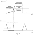
- the horizontal axis of the figure in the upper half of Fig. 5 represents time and the vertical axis represents the braking force.
- a first stage in which the regenerative braking force is provided only by the regenerative braking system to meet the total braking force requirement, and the curve of the regenerative braking force is coincide with the curve of the total braking force (for clarity, the two curves are shown separately in the figure in a schematic manner); and a second stage, with the continuous increasing of the total braking force requirement, after the friction braking force is produced, the friction braking force provided by the friction braking system (in the present application, the electro-mechanical braking system) is added to the regenerative braking force provided by the regenerative braking system to meet the total braking force requirement.
- the response time between the first stage and the second stage is caused by the time required for the friction braking system to move from the position with the clearance of the preset value to the compression position.
- the friction braking system i.e. the electro-mechanical braking system
- the friction braking system is controlled to reach and maintain at the position with the brake clearance of the preset value before the friction braking force is required (i.e. when the regenerative braking force can meet the total braking force requirement required by the vehicle), so that the friction braking force can be produced by the electro-mechanical braking device in a shorter time when the friction braking force is required, and the response time of the friction braking system is significantly shortened.
- a general-purpose processor may be a microprocessor. But in the alternative, the processor may be any conventional processor, controller, microcontroller, or state machine.
- a processor may also be implemented as a combination of computing apparatuses, e.g. a combination of a DSP and a microprocessor, a plurality of microprocessors, one or more microprocessors in conjunction with a DSP core, or any other such configurations.
- a software module may reside in RAM memory, flash memory, ROM memory, EPROM memory, EEPROM memory, a register, a hard disk, a removable disk, a CD-ROM, or any other form of storage media known in the field.
- An exemplary storage medium is connected to the processor such that the processor can read information from, and write information to, the storage medium.
- the storage medium may be integral to the processor.
- the processor and the storage medium may reside in an ASIC.
- the ASIC may reside in a user terminal.
- the processor and the storage medium may reside as discrete components in a user terminal.
Landscapes
- Engineering & Computer Science (AREA)
- Mechanical Engineering (AREA)
- Transportation (AREA)
- Power Engineering (AREA)
- General Engineering & Computer Science (AREA)
- Physics & Mathematics (AREA)
- Electromagnetism (AREA)
- Electric Propulsion And Braking For Vehicles (AREA)
- Regulating Braking Force (AREA)
- Fluid Mechanics (AREA)
Abstract
Description
- The present application relates to braking technology, and more particularly to electro-mechanical braking technology.
- Chinese patent publication No.
CN110103926A discloses a braking system. If an electric braking force is not required, when difference between a maximum regenerative braking force and an actual regenerative braking force is below a set difference, a piston of an electric braking device is moved to a waiting position to reduce a gap between a friction member and a rotating body; and when the difference between the two is greater than the set difference, the piston is in a retracted position with a greater gap. The technical effect that this publication intends to achieve is to reduce the gap and ensure good responsiveness when the possibility of producing the electric braking force increases. The action of clearance reduction should be performed when there is no electric braking requirement, so as to achieve the effect of rapid response. However, in the prior art, the clearance reduction is only performed when the actual regenerative braking force is close to the maximum regenerative braking force. Under the method in the prior art, there is no time to perform the action of the clearance reduction in the situation where the brake pedal is lightly pressed on followed by an emergency heavy press. - The following presents a simplified summary of one or more aspects in order to provide a basic understanding of such aspects. This summary is not an extensive overview of all contemplated aspects, and is not intended to identify key or critical elements of all aspects or define the scope of any or all aspects. The sole purpose is to provide some concepts of one or more aspects in simplified form for a more detailed description later on.
- In order to overcome the above drawbacks in the prior art, the present invention provides a braking method and a braking system capable of shortening the response time of a friction braking system. In cases from light braking to emergency braking, the present invention can shorten the response time, and improve safety and brake smoothness.
- According to the first aspect of the present disclosure, a braking method for a vehicle performed by an electro-mechanical braking system is provided. The vehicle includes an electro-mechanical braking system and a regenerative braking system. The electro-mechanical braking system includes at least one axle control unit, and a plurality of electro-mechanical braking devices provided at ends of wheels and driven by motors to apply friction braking forces to the wheels, and in response to a braking requirement, the electro-mechanical braking devices are controlled by the axle control unit to switch between a state in which friction braking is not applied and a state in which the friction braking is applied. The method includes: setting a brake clearance between a brake pad and a brake disc of each of the electro-mechanical braking devices to an initial value; determining whether there is a braking requirement; determining whether regenerative braking is produced by a drive motor of the regenerative braking system; and in response to producing of the regenerative braking, controlling the electro-mechanical braking device to move the brake pad, such that the brake clearance is at a preset value, wherein the preset value is smaller than the initial value.
- According to the second aspect of the present disclosure, an electro-mechanical braking system is provided. The electro-mechanical braking system includes at least one axle control unit, and a plurality of electro-mechanical braking devices provided at ends of wheels and driven by motors to apply friction braking forces to the wheels, the electro-mechanical braking devices are controlled by the axle control unit to switch between a state in which friction braking is not applied and a state in which the friction braking is applied in response to a braking requirement; a memory in communication connection with the at least one axle control unit, wherein the memory stores thereon machine-executable instructions; and a processor in communication connection with the at least one axle control unit, and the memory, wherein the machine-executable instructions, when executed by the processor, cause the electro-mechanical braking system to perform the steps of the method described according to the first aspect of the present disclosure.
- Compared with the prior art, in the present application, the friction braking system for a vehicle is realized by an Electro-Mechanical Braking (EMB) system. Before friction braking is required by the vehicle, the electro-mechanical braking device is controlled by the electro-mechanical braking system to reduce the brake clearance, such that the friction braking system can quickly get involved when friction braking is required. Through the application of the above-mentioned control strategy, the response time of the vehicle to the friction braking requirement is shortened, so that the connection and switch between the friction braking and the regenerative braking is smoother, and the comfort during braking is effectively improved.
- The above features and advantages of the present invention can be better understood with the reading of the detailed description of the embodiments of the present disclosure in conjunction with the following drawings. In the drawings, components are not necessarily drawn to scale, and components having similar relevant characteristics or features may have the same or similar reference numerals.
-
Fig. 1 illustrates a schematic architectural diagram of an electro-mechanical braking system according to some aspects of the present disclosure; -
Fig. 2 illustrates a schematic architectural diagram of a system including a braking system for a vehicle and other components of the vehicle according to some aspects of the present disclosure; -
Figs. 3A and 3B are schematic structural diagrams of an electro-mechanical braking device at an initial value of a brake clearance and a preset value of a brake clearance, respectively; -
Fig. 4 shows a flowchart of a braking method according to some aspects of the present disclosure; and -
Fig. 5 illustrates a plot of a braking force and a brake clearance during composite braking according to some aspects of the present disclosure. - Unless specifically stated otherwise, it should be appreciated that modules/components referenced with the same/similar reference numbers across the various figures generally refer to the same modules/components.
- The list of reference numerals:
- 20A, 20B
- axle control unit;
- 31
- right front wheel;
- 32
- left front wheel;
- 33
- right rear wheel;
- 34
- left rear wheel; and
- 311, 321, 331, 341
- electro-mechanical braking device.
- The following will refer to particular specific embodiments to illustrate the implementation modes of the present invention. Those skilled in the art can easily understand the other advantages and effects of the present invention from the content disclosed herein. While the description of the invention will be presented in connection with the preferred embodiments, it is not intended to limit the features of the invention to the implementation modes. Rather, the introduction of the invention in connection with the implementation modes is intended to cover such alternatives and modifications that may be extended based on the claims of the present invention. In the following description, numerous specific details are set forth in order to provide a thorough understanding of the present invention. The invention may be implemented without these details. Furthermore, some of the specific details are omitted from the description in order to avoid mixing or obscuring the focus of the present invention.
- In a vehicle where part or all of power is provided by a drive motor, a composite braking system composed of a friction braking system providing friction braking and a regenerative braking system providing regenerative (electric feedback) braking is often used as a braking system for the vehicle. In the regenerative braking system, a drive motor is switched to an engine for operation and a rotor of the drive motor is driven to rotate by inertia of the vehicle, so that a reverse torque is produced, and a part of kinetic energy or potential energy is converted into electric energy for recovery, meanwhile a braking force is provided to the vehicle. In the friction braking system, a mechanical transmission mechanism is driven to, for example, push a brake pad to rub against a brake disc, so that a braking force is produced. In the present application, the friction braking system in the composite braking system is realized by an Electro-Mechanical Braking (EMB) system. Unlike traditional braking systems that use hydraulic pressure or air pressure as power source, in the electro-mechanical braking system, electric energy is directly used as power source, and the electric energy is converted into a friction braking force acting on wheels through a brake motor and a mechanical transmission mechanism to apply service brake and parking brake. It is a pure drive-by-wire braking system with the characteristics of high energy efficiency, rapid response, and environmental friendliness, and can be well adapted to assisted driving and unmanned driving systems.
-
Fig. 1 illustrates a schematic architectural diagram of an electro-mechanical braking system 100 according to some aspects of the present disclosure. - As shown in
Fig. 1 , the electro-mechanical braking system 100 includes twoaxle control units mechanical braking devices wheels -
Axle control units mechanical braking devices axle control unit - As further shown in
Fig. 3A , the electro-mechanical braking devices brake motor 230 for producing a braking force, and a mechanical transmission mechanism driven by thebrake motor 230. Taking a disc brake as an example, through thebrake motor 230, electrical power is converted to mechanical power to drive the mechanical transmission mechanism to push thebrake pad 238 toward or away from thebrake disc 239, so that a friction braking force is produced or removed. The electro-mechanical braking devices brake motor controller 237 that controls rotation amount of thebrake motor 230 to produce the required braking force based on the braking force requirement sent by theaxle control unit axle control unit mechanical braking devices - The electro-
mechanical braking devices mechanical braking devices - The electro-
mechanical braking system 100 may further include a memory (not shown), having machine-executable instructions stored thereon, in communication connection with at least oneaxle control unit axle control unit mechanical braking system 100 to perform various operations. - The electro-
mechanical braking system 100 as shown inFig. 1 may be implemented in a vehicle that is partially or fully powered by a drive motor. In some examples, the electro-mechanical braking system 100 may be implemented in a battery electric vehicle or a hybrid vehicle where a drive motor is used as power source. In some examples, the vehicle may further include a drive motor controller for controlling the motor. In some examples, the drive motor controller may be implemented as an independent module. In some examples, the drive motor controller may be integrated into the axle control unit in the electro-mechanical braking system 100 or into a vehicle control unit (VCU) of the vehicle. In some examples, the vehicle may further include a drive system controller for controlling a drive system of the vehicle, and a wheel speed sensor for detecting wheel speed. In some examples, a wheel speed sensor may be arranged in correspondence with each of thewheels mechanical braking system 100 may be in communication connection with one or more of a drive motor controller, a drive system controller of a vehicle, a vehicle control unit (VCU), a wheel speed sensor, a brake pedal, and/or an accelerator pedal. - Reference is next made to
Fig. 2 , which illustrates a schematic architectural diagram of asystem 200 including a vehicle braking system and other components of the vehicle according to some aspects of the present disclosure. In an embodiment of the present application, a braking system for the vehicle may include a friction braking system providing a friction braking force and a regenerative braking system providing a regenerative braking force. In an embodiment of the present application, the friction braking system may be implemented by the electro-mechanical braking system 100 as shown inFig. 1 . - As shown in
Fig. 2 , thesystem 200 may include abraking system 201 for the vehicle. Thevehicle braking system 201 may include an electro-mechanical braking system 202 that provides a friction braking force. In some examples, an electro-mechanical braking system 202 may be an example of the electro-mechanical braking system 100 as shown inFig. 1 . The electro-mechanical braking system 202 may include at least oneaxle control unit mechanical braking devices mechanical braking devices brake motor 230, and amechanical transmission mechanism 231. In some examples, the electro-mechanical braking devices brake motor controller 237, and may each include abraking force sensor 212, amotor voltage sensor 213, a motorcurrent sensor 214, a motorrotational position sensor 215, and/orother sensors 216. Thebraking system 201 for the vehicle further includes aregenerative braking system 203. Theregenerative braking system 203 includes adrive motor 220 and adrive motor controller 221. In theregenerative braking system 203, thedrive motor 220 is switched to an engine for operation and a rotor of the drive motor is driven to rotate by inertia of the vehicle, so that a reverse torque is produced, and a part of the kinetic energy or potential energy is converted into electric energy for recovery, whereby a regenerative braking force is provided to the vehicle. In some examples, thedrive motor controller 221 may be integrated into theaxle control unit mechanical braking system 202 or a vehicle control unit (VCU) 302 in thesystem 200. - As shown in
Fig. 2 , thesystem 200 may further include a vehicledrive system controller 301, a vehicle control unit (VCU) 302, awheel speed sensor 303, and a brake pedal and/or anaccelerator pedal 304. In the configuration shown inFig. 2 , theaxle control unit mechanical braking devices braking force sensor 212,motor voltage sensor 213, motorcurrent sensor 214, motorrotational position sensor 215, and/orother sensors 216, and brake motor controllers). Theaxle control unit drive motor controller 221, a vehicledrive system controller 301, a vehicle control unit (VCU) 302, awheel speed sensor 303, and a brake pedal and/or anaccelerator pedal 304. - When braking is required, for example, when a user steps on a brake pedal, the braking system for the vehicle determines a total braking force required by the vehicle based on various factors such as current vehicle speed, depth and speed at which the user steps on the pedal, etc. If the required total braking force is small, it may be provided completely by the regenerative braking system, i.e. the electro-mechanical braking system is not required to produce a friction braking force. If the total braking force required by the vehicle exceeds an available maximum regenerative braking force, the total braking force required by the vehicle is required to be provided by both the regenerative braking force and the friction braking force. In the configuration shown in
Fig. 2 , the total braking force required by the vehicle may be provided by both the friction braking force provided by the electro-mechanical braking system 202 and the regenerative braking force provided by theregenerative braking system 203. During braking, distribution of the total braking force between the regenerative braking force and the friction braking force is dynamically changed. Taking a disc brake as an example, through thebrake motor 230, electrical power is converted to mechanical power to drive the mechanical transmission mechanism to push thebrake pad 238 toward or away from thebrake disc 239 to produce the required braking force. In response to a friction braking requirement, theaxle control unit mechanical braking system 202 controls rotation amount of the brake motor to push thebrake pads 238 of the electro-mechanical braking devices brake disc 239, so that a braking force is produced and thus a friction braking force is provided to the vehicle. As shown inFigs. 3A and 3B , as thebrake pad 238 moves towards thebrake disc 239, a brake clearance C decreases to 0; and when the brake clearance just decreases to 0, thebrake pad 238 is in slight contact with thebrake disc 239, but no friction braking force is produced; the brake motor can continue to rotate, thebrake pad 238 continues to be pushed by the mechanical transmission mechanism, so that thebrake pad 238 is pressed tightly against thebrake disc 239, and the friction braking force is produced. As thebrake pad 238 moves away from thebrake disc 239, the brake clearance C increases. The time between the receipt of the friction braking requirement and the application of the friction force to the wheels in the electro-mechanical braking system affects the smoothness of switching between braking modes, thus affecting the comfort during braking. - A
braking method 400 according to some aspects of the present invention is described below in conjunction withFigs. 2 to 4 . In some examples, themethod 400 may be performed, for example, by the electro-mechanical braking system Figs. 1 and2 providing a friction braking force. - The
method 400 may include:step 420, acquiring regenerative braking information. In some examples,step 420 may include obtaining regenerative braking information by theaxle control unit drive motor controller 221, the vehicledrive system controller 301, and thevehicle control unit 302. In some examples, the regenerative braking information may include information on whether a regenerative braking force was applied and/or information on magnitude of the regenerative braking force. The method for determining whether a regenerative braking force was applied includes: (1) the wheels are driven to move by the drive motors, the drive motor shaft is subjected to a positive torque from the drive motor and a negative torque from the wheels, and when regenerative braking is performed, the drive motor stops producing a driving force for movement, and the motor shaft is driven in a positive direction by inertia of the wheels; and therefore, torques in opposite directions are received by the motor shaft before and after the regenerative braking, and once direction of the torque received by the drive motor shaft is measured to change from a negative direction to a positive direction by the torque sensor, it means that the regenerative braking is performed; and (2) when a drive power supply is turned off, the drive power supply neither output current nor produce electromotive force, the motor shaft is driven to rotate by inertia of the wheels, so that regenerative current and electromotive force are produced, and once the regenerative current and electromotive force are measured by an ammeter or an electromotive force sensor, it means that the regenerative braking is performed. - The
method 400 may include:step 440, in response to the regenerative braking force being applied to the wheels, controlling, by theaxle control unit brake motor 230 to drive themechanical transmission mechanism 231 to operate until the brake clearance C between thebrake pad 238 and thebrake disc 239 reaches a preset value, which is smaller than an initial value of the brake clearance when braking is not required. - The preset value of the brake clearance C is in a range of 0≤C≤0.1 mm. Here, C=0 means that the brake pad is just moved to a position where it is in slight contact with the brake disc, and there is no pressure or friction therebetween. This position may be determined by the
braking force sensor 212, themotor voltage sensor 213, the motorcurrent sensor 214, the motorrotational position sensor 215, and/orother sensors 216 as shown inFig. 2 . Illustratively, the braking force sensor, such as a pressure sensor, is used to detect the pressure between the brake pad and the brake disc. When the brake pad is not in contact with the brake disc, no signal is output by the pressure sensor. When the brake pad is in contact with the brake disc, the pressure sensor outputs a pressure signal. In this case, it can be determined that the electro-mechanical braking device is driven to the position of slight contact. In addition, the signals output by themotor voltage sensor 213, the motorcurrent sensor 214, and the motorrotational position sensor 215 may be referred to for checking to improve accuracy of position confirmation. - In some examples, the
method 400 may optionally include, prior to step 420:step 410, determining whether braking is required. In some examples,step 410 may include determining, by theaxle control unit accelerator pedal 304, the current vehicle speed obtained from thewheel speed sensor 303, etc. In some examples, determining whether braking is required may include determining, by theaxle control unit method 400 may optionally include:step 435, in response to a braking requirement of switching from the regenerative braking force to the combination of the regenerative braking force and the friction braking force, controlling the electro-mechanical braking device to eliminate the brake clearance and move the brake pad to press tightly against the brake disc, so that the friction braking force is produced, and the electro-mechanical braking device is in a compression position. In some examples, themethod 400 may additionally include in response to a braking requirement of removing only the friction braking force but still applying the regenerative braking force, controlling the electro-mechanical braking device to move to a position with the clearance of the preset value. In some examples, themethod 400 may additionally and/or alternatively include, in response to the braking requirement of completely removing the braking force, rotating the brake motor in a reverse direction to retract the electro-mechanical braking device from the compression position or the position with the clearance of the preset value to the position with the clearance of the initial value, as shown instep 415. - In some examples, the steps of the
method 400 are repeated during a braking process. In some examples, during the period that the brake pedal is stepped on and/or the accelerator pedal is released, the steps of themethod 400 are repeated at a certain time interval, e.g. the steps of themethod 400 are performed once every 10 ms. Those skilled in the art should understand that the time interval for performing the steps of themethod 400 may be determined in any other suitable manner without departing from the scope of the present disclosure. - According to various embodiments of the present application, when friction braking is not required, the electro-mechanical braking device is retracted to the position with the clearance of the preset value, so that the electro-mechanical braking system can rapidly preform friction braking when friction braking is required. Not only the response time is shorten, but also the brake motor is prevented from driving the
transmission mechanism 231, in the situation where the brake pedal is lightly pressed on followed by an emergency heavy press, causing thebrake pad 238 moves quickly towards thebrake disc 239 and thus thebrake pad 238 collides with thebrake disc 239, which makes passengers feel a sense of jerking. The horizontal axis of the figure in the upper half ofFig. 5 represents time and the vertical axis represents the braking force. It can be seen that the total braking force goes through two stages of linear change with different slopes and then enters a stable stage. The regenerative braking force goes through a stage of linear growth and then reaches and remains at the level of the maximum regenerative braking force. The braking process shown inFig. 5 may include: a first stage, in which the regenerative braking force is provided only by the regenerative braking system to meet the total braking force requirement, and the curve of the regenerative braking force is coincide with the curve of the total braking force (for clarity, the two curves are shown separately in the figure in a schematic manner); and a second stage, with the continuous increasing of the total braking force requirement, after the friction braking force is produced, the friction braking force provided by the friction braking system (in the present application, the electro-mechanical braking system) is added to the regenerative braking force provided by the regenerative braking system to meet the total braking force requirement. The response time between the first stage and the second stage is caused by the time required for the friction braking system to move from the position with the clearance of the preset value to the compression position. The differences between the present invention and the prior art can be more clearly observed in the situation where the brake pedal is lightly pressed on followed by an emergency heavy press. - In an embodiment according to the present application represented by dot dash lines, the friction braking system (i.e. the electro-mechanical braking system) is controlled to reach and maintain at the position with the brake clearance of the preset value before the friction braking force is required (i.e. when the regenerative braking force can meet the total braking force requirement required by the vehicle), so that the friction braking force can be produced by the electro-mechanical braking device in a shorter time when the friction braking force is required, and the response time of the friction braking system is significantly shortened.
- Technicians in this field can understand that various explanatory logic blocks, modules, circuits, and algorithm steps described in conjunction with the disclosed embodiments herein can be implemented as electronic hardware, computer software, or a combination of the two. To clearly illustrate this interchangeability of hardware and software, various illustrative components, blocks, modules, circuits, and steps have been described above generally in terms of their functionality.
- Whether such functionality is implemented as hardware or software depends upon the particular application and design constraints imposed on the overall system. Technicians can achieve the described functionality in different ways for each specific application, but such implementation decisions should not be interpreted as departing from the scope of the present invention.
- The various explanatory logical blocks, and circuits described in connection with the embodiments disclosed herein may be implemented or performed with a general-purpose processor, a digital signal processor (DSP), an application-specific integrated circuit (ASIC), a field programmable gate array (FPGA) or other programmable logic devices, discrete gate or transistor logic, discrete hardware components, or any combination thereof designed to perform the functions described herein. A general-purpose processor may be a microprocessor. But in the alternative, the processor may be any conventional processor, controller, microcontroller, or state machine. A processor may also be implemented as a combination of computing apparatuses, e.g. a combination of a DSP and a microprocessor, a plurality of microprocessors, one or more microprocessors in conjunction with a DSP core, or any other such configurations.
- The steps of a method or an algorithm described in connection with the embodiments disclosed herein may be embodied directly in hardware, in a software module executed by a processor, or in a combination of the two. A software module may reside in RAM memory, flash memory, ROM memory, EPROM memory, EEPROM memory, a register, a hard disk, a removable disk, a CD-ROM, or any other form of storage media known in the field. An exemplary storage medium is connected to the processor such that the processor can read information from, and write information to, the storage medium. In the alternative, the storage medium may be integral to the processor. The processor and the storage medium may reside in an ASIC. The ASIC may reside in a user terminal. In the alternative, the processor and the storage medium may reside as discrete components in a user terminal.
- The previous description of the present disclosure is provided to enable any person skilled in the art to make or use the present disclosure. Various modifications to this disclosure will be apparent to those skilled in the art, and the universal principles defined herein can be applied to other variants without departing from the spirit or scope of this disclosure. Therefore, this disclosure is not intended to be limited to the examples and designs described herein, but should be granted the widest scope consistent with the principles and novel features disclosed herein.
Claims (8)
- A braking method for a vehicle performed by an electro-mechanical braking system, the vehicle comprising the electro-mechanical braking system and a regenerative braking system, the electro-mechanical braking system comprising at least one axle control unit and a plurality of electro-mechanical braking devices provided at ends of wheels and driven by motors to apply friction braking to the wheels, the electro-mechanical braking devices are controlled by the axle control unit to switch between a state in which friction braking is not applied and a state in which friction braking is applied in response to a braking requirement, wherein the method comprises:setting a brake clearance between a brake pad and a brake disc of each of the electro-mechanical braking devices to an initial value;determining whether there is the braking requirement;determining whether regenerative braking is produced by a drive motor of the regenerative braking system; andin response to producing of the regenerative braking, controlling the electro-mechanical braking device to move the brake pad, such that the brake clearance is at a preset value, wherein the preset value is smaller than the initial value.
- The method of claim 1, characterized by further comprising:in case that a maximum regenerative braking meets the braking requirement, maintaining the brake clearance at the preset value; andin case that the maximum regenerative braking does not meet the braking requirement, controlling the electro-mechanical braking device to move the brake pad, such that the brake pad is pressed tightly against the brake disc and friction braking is produced until a sum of the regenerative braking and the friction braking meets the braking requirement.
- The method of claim 2, characterized in that, in case that the maximum regenerative braking meets the braking requirement after the friction braking is performed, the electro-mechanical braking device is controlled to move the brake pad, such that the brake clearance is increased to the preset value.
- The method of claim 1, characterized by further comprising:
in response to determining that there is no braking requirement, controlling the electro-mechanical braking device to move the brake pad, such that the brake clearance is of the initial value. - The method of claim 1, characterized in that, determining whether regenerative braking is produced by a drive motor of the regenerative braking system comprises:measuring whether torque direction of a drive motor shaft of the drive motor of the regenerative braking system changes from a negative direction to a positive direction; ormeasuring a regenerative current or electromotive force when a drive power supply is turned off.
- The method of claim 1, characterized in that the preset value C of the brake clearance meets 0 < C<0.1 mm.
- The method of claim 1, characterized in that, in case that the preset value C of the brake clearance is equal to 0, controlling the electro-mechanical braking device to make the brake pad in slight contact with the brake disc without producing friction braking.
- An electro-mechanical braking system, comprising:at least one axle control unit;a plurality of electro-mechanical braking devices provided at ends of wheels and driven by motors to apply friction braking forces to the wheels, the electro-mechanical braking devices are controlled by the axle control unit to switch between a state in which friction braking is not applied and a state in which the friction braking is applied in response to a braking requirement;a memory in communication connection with the at least one brake controller, wherein the memory stores thereon machine-executable instructions; anda processor in communication connection with the at least one axle control unit, and the memory, wherein the machine-executable instructions, when executed by the processor, cause the electro-mechanical braking system to perform operations of the method of any one of claims 1 to 7.
Applications Claiming Priority (1)
| Application Number | Priority Date | Filing Date | Title |
|---|---|---|---|
| CN202211609634.8A CN118288803A (en) | 2022-12-14 | 2022-12-14 | Braking method and braking system |
Publications (1)
| Publication Number | Publication Date |
|---|---|
| EP4385794A1 true EP4385794A1 (en) | 2024-06-19 |
Family
ID=89901242
Family Applications (1)
| Application Number | Title | Priority Date | Filing Date |
|---|---|---|---|
| EP23216500.1A Pending EP4385794A1 (en) | 2022-12-14 | 2023-12-14 | Braking method for a vehicle and electro-mechanical braking system |
Country Status (3)
| Country | Link |
|---|---|
| US (1) | US20240198987A1 (en) |
| EP (1) | EP4385794A1 (en) |
| CN (1) | CN118288803A (en) |
Citations (5)
| Publication number | Priority date | Publication date | Assignee | Title |
|---|---|---|---|---|
| US20190232790A1 (en) * | 2018-02-01 | 2019-08-01 | Toyota Jidosha Kabushiki Kaisha | Vehicle brake system |
| US10654454B2 (en) * | 2017-08-07 | 2020-05-19 | Toyota Jidosha Kabushiki Kaisha | Vehicle brake system |
| US10899327B2 (en) * | 2015-09-09 | 2021-01-26 | Ntn Corporation | Electric brake device |
| US20220032885A1 (en) * | 2018-09-26 | 2022-02-03 | Hitachi Astemo, Ltd. | Electric brake, and control device |
| DE102022104252A1 (en) * | 2021-02-23 | 2022-08-25 | Hyundai Mobis Co., Ltd. | Braking system for a vehicle capable of regenerative and hydraulic braking and method of controlling the same |
Family Cites Families (5)
| Publication number | Priority date | Publication date | Assignee | Title |
|---|---|---|---|---|
| US6250436B1 (en) * | 1998-07-31 | 2001-06-26 | Tokico Ltd. | Motor-driven brake apparatus |
| US20140042800A1 (en) * | 2012-08-10 | 2014-02-13 | Samsung Techwin Co., Ltd. | Brake system and method of controlling the same |
| JP6282424B2 (en) * | 2013-09-04 | 2018-02-21 | Ntn株式会社 | Electric brake device |
| EP2955408B1 (en) * | 2014-06-13 | 2019-11-20 | Meritor Heavy Vehicle Braking Systems (UK) Limited | Braking component replacement system and method |
| DE112022005682T5 (en) * | 2021-11-30 | 2024-09-19 | Hitachi Astemo, Ltd. | VEHICLE CONTROL DEVICE AND VEHICLE CONTROL METHOD |
-
2022
- 2022-12-14 CN CN202211609634.8A patent/CN118288803A/en active Pending
-
2023
- 2023-12-13 US US18/538,433 patent/US20240198987A1/en active Pending
- 2023-12-14 EP EP23216500.1A patent/EP4385794A1/en active Pending
Patent Citations (6)
| Publication number | Priority date | Publication date | Assignee | Title |
|---|---|---|---|---|
| US10899327B2 (en) * | 2015-09-09 | 2021-01-26 | Ntn Corporation | Electric brake device |
| US10654454B2 (en) * | 2017-08-07 | 2020-05-19 | Toyota Jidosha Kabushiki Kaisha | Vehicle brake system |
| US20190232790A1 (en) * | 2018-02-01 | 2019-08-01 | Toyota Jidosha Kabushiki Kaisha | Vehicle brake system |
| CN110103926A (en) | 2018-02-01 | 2019-08-09 | 丰田自动车株式会社 | Vehicle brake system |
| US20220032885A1 (en) * | 2018-09-26 | 2022-02-03 | Hitachi Astemo, Ltd. | Electric brake, and control device |
| DE102022104252A1 (en) * | 2021-02-23 | 2022-08-25 | Hyundai Mobis Co., Ltd. | Braking system for a vehicle capable of regenerative and hydraulic braking and method of controlling the same |
Also Published As
| Publication number | Publication date |
|---|---|
| CN118288803A (en) | 2024-07-05 |
| US20240198987A1 (en) | 2024-06-20 |
Similar Documents
| Publication | Publication Date | Title |
|---|---|---|
| US6989644B2 (en) | Regenerative braking system and method using air conditioning system of electric vehicle | |
| JP2001270431A (en) | Method for controlling regenerative cooperating brake system | |
| CN102407785A (en) | Devices for controlling motor torque | |
| CN108454435A (en) | Electric vehicle based on accelerator pedal accidentally accelerates judgement system and its operating method | |
| JP2022056583A (en) | Vehicle control device, vehicle control method and vehicle control system | |
| JP7414490B2 (en) | Control device | |
| CN111391880A (en) | Control method and control system for air-electricity hybrid braking of locomotive | |
| CN113799614A (en) | Braking energy recovery control method and system for four-wheel independent drive electric vehicle | |
| US10112488B2 (en) | Electrically powered vehicle | |
| KR20130057052A (en) | In wheel motor system and abs operation method thereof | |
| CN117734652A (en) | Brake system for vehicle, wheel end brake device and vehicle | |
| US20240198987A1 (en) | Braking method and braking system | |
| JP5685088B2 (en) | Braking device for vehicle | |
| KR100534718B1 (en) | Regeneration braking control method for 4 wheel hybrid electric vehicle | |
| JP7371413B2 (en) | Driving support device for electric vehicles | |
| JP2020147078A (en) | Vehicle control device | |
| CN118003899A (en) | Method for adjusting the coasting energy recovery intensity of electric vehicles suitable for novice transition period | |
| JPH06253406A (en) | Brake device for electric railcar | |
| JP7698445B2 (en) | Control device | |
| JP2001322540A (en) | Vehicle deceleration control device | |
| JP7383405B2 (en) | Brake control device | |
| KR100534796B1 (en) | Braking control method for 4 wheel hybrid electric vehicle | |
| KR20170079022A (en) | The application of Vehicle Decelerate and stop Function by Using Regenerative breaking system for Autonomous Electric Vehicles | |
| KR101419603B1 (en) | Apparatus for controlling of regenerative breaking in electric vehicle using brake pedal positional information and method thereof | |
| JP7828197B2 (en) | Control device |
Legal Events
| Date | Code | Title | Description |
|---|---|---|---|
| PUAI | Public reference made under article 153(3) epc to a published international application that has entered the european phase |
Free format text: ORIGINAL CODE: 0009012 |
|
| STAA | Information on the status of an ep patent application or granted ep patent |
Free format text: STATUS: THE APPLICATION HAS BEEN PUBLISHED |
|
| AK | Designated contracting states |
Kind code of ref document: A1 Designated state(s): AL AT BE BG CH CY CZ DE DK EE ES FI FR GB GR HR HU IE IS IT LI LT LU LV MC ME MK MT NL NO PL PT RO RS SE SI SK SM TR |
|
| RAP1 | Party data changed (applicant data changed or rights of an application transferred) |
Owner name: HALDEX AKTIEBOLAG |
|
| STAA | Information on the status of an ep patent application or granted ep patent |
Free format text: STATUS: REQUEST FOR EXAMINATION WAS MADE |
|
| 17P | Request for examination filed |
Effective date: 20241218 |
|
| STAA | Information on the status of an ep patent application or granted ep patent |
Free format text: STATUS: EXAMINATION IS IN PROGRESS |
|
| 17Q | First examination report despatched |
Effective date: 20250327 |