EP4385778A1 - Driving device - Google Patents
Driving device Download PDFInfo
- Publication number
- EP4385778A1 EP4385778A1 EP23215126.6A EP23215126A EP4385778A1 EP 4385778 A1 EP4385778 A1 EP 4385778A1 EP 23215126 A EP23215126 A EP 23215126A EP 4385778 A1 EP4385778 A1 EP 4385778A1
- Authority
- EP
- European Patent Office
- Prior art keywords
- casing
- driving device
- electric motor
- gear
- cover
- Prior art date
- Legal status (The legal status is an assumption and is not a legal conclusion. Google has not performed a legal analysis and makes no representation as to the accuracy of the status listed.)
- Pending
Links
Images



Classifications
-
- B—PERFORMING OPERATIONS; TRANSPORTING
- B60—VEHICLES IN GENERAL
- B60K—ARRANGEMENT OR MOUNTING OF PROPULSION UNITS OR OF TRANSMISSIONS IN VEHICLES; ARRANGEMENT OR MOUNTING OF PLURAL DIVERSE PRIME-MOVERS IN VEHICLES; AUXILIARY DRIVES FOR VEHICLES; INSTRUMENTATION OR DASHBOARDS FOR VEHICLES; ARRANGEMENTS IN CONNECTION WITH COOLING, AIR INTAKE, GAS EXHAUST OR FUEL SUPPLY OF PROPULSION UNITS IN VEHICLES
- B60K1/00—Arrangement or mounting of electrical propulsion units
-
- B—PERFORMING OPERATIONS; TRANSPORTING
- B60—VEHICLES IN GENERAL
- B60K—ARRANGEMENT OR MOUNTING OF PROPULSION UNITS OR OF TRANSMISSIONS IN VEHICLES; ARRANGEMENT OR MOUNTING OF PLURAL DIVERSE PRIME-MOVERS IN VEHICLES; AUXILIARY DRIVES FOR VEHICLES; INSTRUMENTATION OR DASHBOARDS FOR VEHICLES; ARRANGEMENTS IN CONNECTION WITH COOLING, AIR INTAKE, GAS EXHAUST OR FUEL SUPPLY OF PROPULSION UNITS IN VEHICLES
- B60K6/00—Arrangement or mounting of plural diverse prime-movers for mutual or common propulsion, e.g. hybrid propulsion systems comprising electric motors and internal combustion engines
- B60K6/20—Arrangement or mounting of plural diverse prime-movers for mutual or common propulsion, e.g. hybrid propulsion systems comprising electric motors and internal combustion engines the prime-movers consisting of electric motors and internal combustion engines, e.g. HEVs
- B60K6/22—Arrangement or mounting of plural diverse prime-movers for mutual or common propulsion, e.g. hybrid propulsion systems comprising electric motors and internal combustion engines the prime-movers consisting of electric motors and internal combustion engines, e.g. HEVs characterised by apparatus, components or means specially adapted for HEVs
- B60K6/40—Arrangement or mounting of plural diverse prime-movers for mutual or common propulsion, e.g. hybrid propulsion systems comprising electric motors and internal combustion engines the prime-movers consisting of electric motors and internal combustion engines, e.g. HEVs characterised by apparatus, components or means specially adapted for HEVs characterised by the assembly or relative disposition of components
- B60K6/405—Housings
-
- B—PERFORMING OPERATIONS; TRANSPORTING
- B60—VEHICLES IN GENERAL
- B60H—ARRANGEMENTS OF HEATING, COOLING, VENTILATING OR OTHER AIR-TREATING DEVICES SPECIALLY ADAPTED FOR PASSENGER OR GOODS SPACES OF VEHICLES
- B60H1/00—Heating, cooling or ventilating devices
- B60H1/00357—Air-conditioning arrangements specially adapted for particular vehicles
- B60H1/00385—Air-conditioning arrangements specially adapted for particular vehicles for vehicles having an electrical drive, e.g. hybrid or fuel cell
- B60H1/00392—Air-conditioning arrangements specially adapted for particular vehicles for vehicles having an electrical drive, e.g. hybrid or fuel cell for electric vehicles having only electric drive means
-
- B—PERFORMING OPERATIONS; TRANSPORTING
- B60—VEHICLES IN GENERAL
- B60K—ARRANGEMENT OR MOUNTING OF PROPULSION UNITS OR OF TRANSMISSIONS IN VEHICLES; ARRANGEMENT OR MOUNTING OF PLURAL DIVERSE PRIME-MOVERS IN VEHICLES; AUXILIARY DRIVES FOR VEHICLES; INSTRUMENTATION OR DASHBOARDS FOR VEHICLES; ARRANGEMENTS IN CONNECTION WITH COOLING, AIR INTAKE, GAS EXHAUST OR FUEL SUPPLY OF PROPULSION UNITS IN VEHICLES
- B60K6/00—Arrangement or mounting of plural diverse prime-movers for mutual or common propulsion, e.g. hybrid propulsion systems comprising electric motors and internal combustion engines
- B60K6/20—Arrangement or mounting of plural diverse prime-movers for mutual or common propulsion, e.g. hybrid propulsion systems comprising electric motors and internal combustion engines the prime-movers consisting of electric motors and internal combustion engines, e.g. HEVs
- B60K6/22—Arrangement or mounting of plural diverse prime-movers for mutual or common propulsion, e.g. hybrid propulsion systems comprising electric motors and internal combustion engines the prime-movers consisting of electric motors and internal combustion engines, e.g. HEVs characterised by apparatus, components or means specially adapted for HEVs
- B60K6/24—Arrangement or mounting of plural diverse prime-movers for mutual or common propulsion, e.g. hybrid propulsion systems comprising electric motors and internal combustion engines the prime-movers consisting of electric motors and internal combustion engines, e.g. HEVs characterised by apparatus, components or means specially adapted for HEVs characterised by the combustion engines
-
- B—PERFORMING OPERATIONS; TRANSPORTING
- B60—VEHICLES IN GENERAL
- B60K—ARRANGEMENT OR MOUNTING OF PROPULSION UNITS OR OF TRANSMISSIONS IN VEHICLES; ARRANGEMENT OR MOUNTING OF PLURAL DIVERSE PRIME-MOVERS IN VEHICLES; AUXILIARY DRIVES FOR VEHICLES; INSTRUMENTATION OR DASHBOARDS FOR VEHICLES; ARRANGEMENTS IN CONNECTION WITH COOLING, AIR INTAKE, GAS EXHAUST OR FUEL SUPPLY OF PROPULSION UNITS IN VEHICLES
- B60K6/00—Arrangement or mounting of plural diverse prime-movers for mutual or common propulsion, e.g. hybrid propulsion systems comprising electric motors and internal combustion engines
- B60K6/20—Arrangement or mounting of plural diverse prime-movers for mutual or common propulsion, e.g. hybrid propulsion systems comprising electric motors and internal combustion engines the prime-movers consisting of electric motors and internal combustion engines, e.g. HEVs
- B60K6/22—Arrangement or mounting of plural diverse prime-movers for mutual or common propulsion, e.g. hybrid propulsion systems comprising electric motors and internal combustion engines the prime-movers consisting of electric motors and internal combustion engines, e.g. HEVs characterised by apparatus, components or means specially adapted for HEVs
- B60K6/26—Arrangement or mounting of plural diverse prime-movers for mutual or common propulsion, e.g. hybrid propulsion systems comprising electric motors and internal combustion engines the prime-movers consisting of electric motors and internal combustion engines, e.g. HEVs characterised by apparatus, components or means specially adapted for HEVs characterised by the motors or the generators
-
- H—ELECTRICITY
- H02—GENERATION; CONVERSION OR DISTRIBUTION OF ELECTRIC POWER
- H02K—DYNAMO-ELECTRIC MACHINES
- H02K11/00—Structural association of dynamo-electric machines with electric components or with devices for shielding, monitoring or protection
- H02K11/30—Structural association with control circuits or drive circuits
-
- H—ELECTRICITY
- H02—GENERATION; CONVERSION OR DISTRIBUTION OF ELECTRIC POWER
- H02K—DYNAMO-ELECTRIC MACHINES
- H02K11/00—Structural association of dynamo-electric machines with electric components or with devices for shielding, monitoring or protection
- H02K11/30—Structural association with control circuits or drive circuits
- H02K11/33—Drive circuits, e.g. power electronics
-
- H—ELECTRICITY
- H02—GENERATION; CONVERSION OR DISTRIBUTION OF ELECTRIC POWER
- H02K—DYNAMO-ELECTRIC MACHINES
- H02K7/00—Arrangements for handling mechanical energy structurally associated with dynamo-electric machines, e.g. structural association with mechanical driving motors or auxiliary dynamo-electric machines
- H02K7/006—Structural association of a motor or generator with the drive train of a motor vehicle
-
- H—ELECTRICITY
- H02—GENERATION; CONVERSION OR DISTRIBUTION OF ELECTRIC POWER
- H02K—DYNAMO-ELECTRIC MACHINES
- H02K7/00—Arrangements for handling mechanical energy structurally associated with dynamo-electric machines, e.g. structural association with mechanical driving motors or auxiliary dynamo-electric machines
- H02K7/10—Structural association with clutches, brakes, gears, pulleys or mechanical starters
- H02K7/116—Structural association with clutches, brakes, gears, pulleys or mechanical starters with gears
-
- B—PERFORMING OPERATIONS; TRANSPORTING
- B60—VEHICLES IN GENERAL
- B60K—ARRANGEMENT OR MOUNTING OF PROPULSION UNITS OR OF TRANSMISSIONS IN VEHICLES; ARRANGEMENT OR MOUNTING OF PLURAL DIVERSE PRIME-MOVERS IN VEHICLES; AUXILIARY DRIVES FOR VEHICLES; INSTRUMENTATION OR DASHBOARDS FOR VEHICLES; ARRANGEMENTS IN CONNECTION WITH COOLING, AIR INTAKE, GAS EXHAUST OR FUEL SUPPLY OF PROPULSION UNITS IN VEHICLES
- B60K1/00—Arrangement or mounting of electrical propulsion units
- B60K2001/001—Arrangement or mounting of electrical propulsion units one motor mounted on a propulsion axle for rotating right and left wheels of this axle
-
- B—PERFORMING OPERATIONS; TRANSPORTING
- B60—VEHICLES IN GENERAL
- B60Y—INDEXING SCHEME RELATING TO ASPECTS CROSS-CUTTING VEHICLE TECHNOLOGY
- B60Y2200/00—Type of vehicle
- B60Y2200/90—Vehicles comprising electric prime movers
- B60Y2200/92—Hybrid vehicles
-
- B—PERFORMING OPERATIONS; TRANSPORTING
- B60—VEHICLES IN GENERAL
- B60Y—INDEXING SCHEME RELATING TO ASPECTS CROSS-CUTTING VEHICLE TECHNOLOGY
- B60Y2400/00—Special features of vehicle units
- B60Y2400/60—Electric Machines, e.g. motors or generators
-
- B—PERFORMING OPERATIONS; TRANSPORTING
- B60—VEHICLES IN GENERAL
- B60Y—INDEXING SCHEME RELATING TO ASPECTS CROSS-CUTTING VEHICLE TECHNOLOGY
- B60Y2400/00—Special features of vehicle units
- B60Y2400/61—Arrangements of controllers for electric machines, e.g. inverters
Definitions
- the technology of the present disclosure relates to a driving device.
- US Patent No. 9,692,277 discloses a driving device that includes an electric motor that drives a wheel of a vehicle, a casing that accommodates the electric motor, an inverter body, and a cover that covers the inverter body.
- the driving device is fixed to a subframe of the vehicle via a bracket.
- vibration is sometimes applied to a cover that covers an inverter body.
- vibration applied to the cover is directly transmitted to the inverter body.
- the present disclosure provides a technology capable of reducing vibration transmitted to a high voltage component covered by a cover.
- a first aspect of the invention relates to a driving device including an electric motor, a gear, a casing, a high voltage component, and a cover.
- the electric motor is configured to drive wheels of a vehicle.
- the gear is connected to the electric motor.
- the casing accommodates at least one of the electric motor and the gear.
- the high voltage component is fixed to a side wall of the casing from the outside of the casing and is electrically connected to the electric motor.
- the cover is fixed to the side wall of the casing from the outside of the casing and covers the high voltage component.
- the cover is connected to a constituent member located outside the cover.
- the casing may accommodate the electric motor and the gear.
- the casing may have a first casing that accommodates the electric motor and a second casing that accommodates the gear.
- the high voltage component, the electric motor, and the gear may be arranged in order of the high voltage component, the electric motor, and the gear along an axial direction parallel to a rotation axis of the electric motor.
- the high-voltage component, the electric motor, and the gear may be arranged in order of the high voltage component, the gear, and the electric motor along an axial direction parallel to a rotation axis of the electric motor.
- the constituent member may include at least one of a vehicle body of the vehicle, a member fixed to the vehicle body, and a vibration generating member, and the cover may be connected to the constituent member through a bracket.
- the vehicle may include a subframe fixed to the vehicle body, and the constituent member may include a supporting mount provided in the subframe.
- the vehicle may include a compressor for air conditioning, and the vibration generating member may include the compressor.
- the vehicle may be a hybrid vehicle including an engine fixed to a vehicle body, and the electric motor and the engine may be arranged along an axial direction parallel to a rotation axis of the electric motor.
- the side wall of the casing may extend in a direction intersecting with a rotation axis of the electric motor of the casing, and the constituent member may face an outer surface of the side wall.
- the side wall of the casing may extend along a rotation axis of the electric motor of the casing and the constituent member may face an outer surface of the side wall.
- the high voltage component may be an inverter or/and a DC/DC converter.
- the high voltage component may be a component with an operating voltage range of above DC 60 V to DC 1500 V, or above AC 30 V to AC 1000 V in root mean square value.
- vibration transmitted from the constituent member located outside the cover is transmitted to the cover that covers the high voltage component.
- the high voltage component is fixed to the side wall of the casing from the outside of the casing. Therefore, the vibration transmitted from the constituent member to the cover is transmitted to the high voltage component through the side wall of the casing.
- vibration transmitted from the constituent member to the high voltage component can be reduced compared to the technology of the related art in which vibration transmitted from the constituent member to the cover is directly transmitted to the high voltage component.
- the casing may accommodate the electric motor and the gear. However, in another embodiment, the casing may not accommodate the gear, for example.
- the casing may include a first casing that accommodates the electric motor and a second casing that accommodates the gear.
- the first casing may accommodate the electric motor and the gear.
- the high voltage component, the electric motor, and the gear may be arranged in this order along an axial direction parallel to a rotation axis of the electric motor.
- the high voltage component, the electric motor, and the gear may be arranged in this order along the axial direction parallel to the rotation axis of the electric motor, or they may be arranged along the axial direction parallel to the rotation axis of the electric motor in order of the electric motor, the high voltage component, and the gear.
- the constituent member may include at least one of a vehicle body of the vehicle, a member fixed to the vehicle body, and a vibration generating member.
- the cover may be connected to the constituent member via a bracket.
- the vehicle may include a subframe fixed to the vehicle body, and the constituent member may include a supporting mount provided on the subframe.
- the constituent member may include a supporting mount provided on the subframe.
- the vehicle may include a compressor for air conditioning, and the vibration generating member may be the compressor.
- the vibration generating member may be the compressor.
- the vehicle may be a hybrid vehicle including an engine fixed to a vehicle body.
- the electric motor and the engine may be arranged along an axial direction parallel to a rotation axis of the electric motor.
- the engine and the motor may be arranged along a direction orthogonal to the rotation axis of the electric motor.
- the side wall of the casing may extend in a direction that intersects a rotation axis of the electric motor of the casing.
- the constituent member may face an outer surface of the side wall.
- the side wall of the casing may extend along a rotation axis of the electric motor of the casing. In this case, the constituent member may face an outer surface of the side wall.
- FIG. 1 illustrates a plan view of an electric vehicle 100 equipped with a driving device 10 of a first example.
- the electric vehicle 100 includes a vehicle body 2, a front drive shaft 5F, a pair of front wheels 4F, a rear drive shaft 5R, a pair of rear wheels 4R, a battery pack 6, a rear suspension member 8, and a compressor 70 in addition to the driving device 10.
- FIG. 1 illustrates the vehicle body 2 of the electric vehicle 100 with a dashed line.
- the electric vehicle 100 in the present disclosure includes electric vehicles as well as fuel cell vehicles.
- FR indicates the front of the electric vehicle 100
- UP indicates the top of the electric vehicle 100
- LH indicates the left side of the electric vehicle 100.
- “up”, “down”, “left”, “right”, “front”, and “rear” are described based on the coordinate system in the drawings.
- One front wheel 4F is provided at one end of the front drive shaft 5F, and the other front wheel 4F is provided at the other end of the front drive shaft 5F.
- one rear wheel 4R is provided at one end of the rear drive shaft 5R, and the other rear wheel 4R is provided at the other end of the rear drive shaft 5R.
- the driving device 10 is located below a rear seat (not illustrated) of the electric vehicle 100 and above the rear suspension member 8. In a modification example, the driving device 10 may be located below a board forming a bottom surface of a luggage space of the electric vehicle 100.
- the driving device 10 drives the rear wheels 4R via the rear drive shaft 5R of the electric vehicle 100.
- the driving device 10 includes a casing 11, an inverter unit 20, a gear unit 30, and a motor unit 40.
- the inverter unit 20 has an inverter 22.
- the gear unit 30 has a link gear 32, a counter gear 33, and a differential gear 34.
- the motor unit 40 has a motor 42.
- the battery pack 6 is arranged below a floor panel 9 (see FIG. 2 ) of the electric vehicle 100.
- the battery pack 6 supplies electric power to the driving device 10.
- the driving device 10 drives the rear wheels 4R.
- the driving device 10 also functions as a generator.
- the battery pack 6 stores electric power supplied from the driving device 10.
- the inverter 22 is connected to the battery pack 6 by a power cable 7.
- the inverter 22 converts direct current power of the battery pack 6 into alternating current power suitable for driving the motor 42.
- the inverter 22 is a high voltage component to which high voltage power is applied.
- the term "high voltage” refers to an operating voltage range of above DC 60 V to DC 1500 V, or above AC 30 V (root mean square value) to AC 1000 V (root mean square value).
- a “high voltage component” in the present disclosure may typically be a component that is electrically connected to the motor 42 and has a function of controlling electric power supplied to the motor 42.
- a cable connected to the motor 42 does not correspond to the "high voltage component”.
- the driving device 10 may incorporate a DC/DC converter that boosts the direct current power of the battery pack 6 instead of, or in addition to, the inverter 22, for example.
- the compressor 70 is located in a front component 3 of the electric vehicle 100.
- the compressor 70 is an air-conditioning compressor that adjusts the temperature of a vehicle cabin of the electric vehicle 100.
- the casing 11 of the driving device 10 is a rectangular box and forms a space for accommodating the motor 42 and a space for accommodating the link gear 32, the counter gear 33, and the differential gear 34 of the gear unit 30.
- the casing 11 has a left side wall 14 at a left end.
- the left side wall 14 is an outer wall that separates the inside and outside of the casing 11 and extends in the vertical direction.
- the driving device 10 is fixed to the rear suspension member 8 via a pair of brackets 60L, 60R and a pair of supporting mounts 50L, 50R.
- the rear suspension member 8 is fixed to an upper surface of the floor panel 9 of the vehicle body 2 of the electric vehicle 100.
- the rear suspension member 8 is a subframe of the electric vehicle 100 formed by combining a plurality of frames.
- the supporting mounts 50L, 50R are members provided on the rear suspension member 8.
- the supporting mount 50L is a member that connects the rear suspension member 8 and the bracket 60L.
- the supporting mount 50R is a member that connects the rear suspension member 8 and the bracket 60R.
- the brackets 60L, 60R have symmetrical shapes with respect to each other.
- the supporting mounts 50L, 50R have symmetrical shapes with respect to each other. This description will primarily focus on the structures of the left bracket 60L and the supporting mount 50L among these components.
- the motor 42 inside the casing 11 is a so-called electric motor, and includes a rotor 44 and a stator core 46.
- the rotor 44 extends in the right and left direction along a rotation axis A1 of the motor 42.
- the rotor 44 is made of a magnetic material and accommodates a permanent magnet (not illustrated) inside.
- the rotor 44 has a motor shaft 47 extending in an axial direction (that is, right and left direction) parallel to the rotation axis A1.
- the motor shaft 47 is rotatably supported by the casing 11 via a pair of bearings 49.
- the inverter unit 20, the gear unit 30, and the motor unit 40 are arranged in this order from the left side along an axial direction parallel to the rotation axis A1. Further, the gear unit 30 is located between the motor 42 and the inverter 22.
- a cooling unit which supplies, to the inverter unit 20, a heat transfer medium for cooling the inverter 22 of the inverter unit 20 may be interposed between the inverter unit 20 and the gear unit 30. That is, in a modification example, in addition to the units 20, 30, and 40, other members may be arranged between the units 20, 30, and 40.
- the size of the driving device 10 in the vertical direction can be reduced compared to a configuration in which the units 20, 30, and 40 are arranged in the vertical direction, respectively.
- the cabin space of the electric vehicle 100 can be enlarged.
- the left side wall 14 extends in a direction intersecting with the rotation axis A1.
- the stator core 46 has a cylindrical shape and extends in the right and left direction along the rotation axis A1.
- the stator core 46 is located radially outside the rotor 44.
- a gap is provided between the stator core 46 and the rotor 44.
- the stator core 46 is made of a magnetic material.
- a stator coil 48 is provided on the stator core 46.
- the stator coil 48 is made of a conductive body and wound around an outer surface of the stator core 46.
- the stator coil 48 of the motor unit 40 is electrically connected to the inverter 22 of the inverter unit 20. When the electric power of the battery pack 6 is supplied to the stator coil 48 through the inverter 22, a magnetic force is generated between the stator coil 48 and the rotor 44. This causes the rotor 44 to rotate around the rotation axis A1.
- the motor shaft 47 extends leftward from the motor unit 40 until it reaches the link gear 32 of the gear unit 30.
- the motor shaft 47 is connected to the link gear 32 of the gear unit 30. That is, the motor 42 is mechanically connected to the link gear 32 via the motor shaft 47. Thereby, rotation of the rotor 44 of the motor 42 is transmitted to the link gear 32.
- the link gear 32 meshes with the counter gear 33.
- the counter gear 33 meshes with the differential gear 34. That is, the link gear 32 is mechanically connected to the differential gear 34 via the counter gear 33.
- the differential gear 34 is mechanically connected to the rear drive shaft 5R. Thereby, the rotation of the link gear 32 is transmitted to the rear drive shaft 5R via the counter gear 33 and the differential gear 34.
- the motor 42 drives the rear wheels 4R through the three gears 32, 33, and 34 of the gear unit 30.
- the gear unit 30 may not include the counter gear 33, for example.
- the link gear 32 and the differential gear 34 may mesh directly.
- the inverter unit 20 includes a cover 21 in addition to the inverter 22.
- the inverter 22 includes a plurality of switching elements.
- the inverter 22 is fixed to the left side wall 14 of the casing 11 with a plurality of bolts B2 from the left side of the casing 11.
- the inverter 22 is fixed to the left side wall 14 of the casing 11 from the outside of the casing 11.
- the cover 21 of the inverter unit 20 has a box shape with an open right side.
- the cover 21 includes an end wall 24, an annular wall 23, and a pair of flanges 26U, 26D.
- An outer peripheral edge of the end wall 24 extending in the vertical direction is connected to the flanges 26U, 26D by the annular wall 23 extending in the right and left direction.
- the inverter 22 is fixed to the left side wall 14 of the casing 11 via the flanges 26U, 26D and the bolts B2 from the left side of the casing 11.
- the casing 11 may further accommodate a smoothing capacitor for smoothing the output of the inverter 22 and/or a filter for suppressing noise from occurring in the input of the inverter 22.
- the bracket 60L is fixed to the end wall 24 of the cover 21 with a plurality of bolts B1.
- the bracket 60L includes a fixing portion that abuts the end wall 24 of the cover 21, and a body portion bent into an L shape.
- a boss of the supporting mount 50L is inserted into a lower end portion of the body portion of the bracket 60L.
- the bracket 60L is fixed to the supporting mount 50L.
- a left side surface of the left side wall 14 faces the supporting mount 50L.
- the bracket 60L may be fixed to the end wall 24 of the cover 21 with an adhesive or by welding.
- the vehicle body 2 (for example, floor panel 9) vibrates.
- vibration of the floor panel 9 is transmitted to the driving device 10 via the rear suspension member 8, the supporting mounts 50L, 50R, and the brackets 60L, 60R.
- the vibration of the inverter 22 which is a high voltage component.
- the inverter 22 is covered with the cover 21, and the cover 21 is fixed to the rear suspension member 8 via the supporting mount 50L and the bracket 60L. Therefore, the vibration of the supporting mount 50L is transmitted through the bracket 60L to the cover 21 covering the inverter 22.
- the inverter 22 is fixed to the left side wall 14 of the casing 11 from the outside of the casing 11. That is, the inverter 22 is not directly fixed to the cover 21 that covers the inverter 22. Therefore, even when vibration is transmitted from the supporting mount 50L to the cover 21, the vibration is not directly transmitted from the cover 21 to the inverter 22.
- the vibration is first transmitted to the left side wall 14 of the casing 11 and transmitted to the inverter 22 after being damped by the left side wall 14.
- vibration transmitted from the supporting mount 50L to the inverter 22 can be reduced.
- a driving device 10A of a second example will be described with reference to FIG. 3 .
- the driving device 10A of the second example differs in the arrangement of the motor unit 40 and the gear unit 30 from the driving device 10 of the first example.
- the inverter unit 20, the motor unit 40, and the gear unit 30 are arranged in this order from the left side along an axial direction (that is, right and left direction) parallel to the rotation axis A1.
- the motor 42 is located between the gear unit 30 and the inverter 22.
- the inverter 22 is fixed to the left side wall 14 of the casing 11 from the outside of the casing 11.
- vibration transmitted from the supporting mount 50L to the inverter 22 can be reduced.
- the second example in addition to the units 20, 30, and 40, it is possible to arrange other members between the units 20, 30, and 40, similar to the configuration described in the first example.
- FIG. 4 illustrates a plan view of the driving device 10B of the third example.
- the driving device 10B of the third example is arranged in a front component 3 (see FIG. 1 ) of an electric vehicle 100B unlike the driving device 10 of the first example.
- a driving device 10B of the third example includes a motor unit 40F and a gear unit 30F, and drives the front wheels 4F (see FIG. 1 ) via the front drive shaft 5F.
- the motor unit 40F has a motor 42F
- the gear unit 30F has a link gear 32F and a differential gear 34F.
- the structure of the motor unit 40F is similar to that of the motor unit 40 of the first example.
- the structure of the gear unit 30F is similar to that of the gear unit 30 of the first example.
- the driving device 10B of the third example is fixed to a floor surface of the front component 3, that is, a floor panel 9C by a left mount 52L, a left bracket 62L, the bolts B1, and a plurality of bolts B3 from the left side. Further, the driving device 10B of the present example is fixed to the floor panel 9C by a right mount 52R, a right bracket 62R, the bolts B1, and the bolts B3 from the right side.
- an inverter unit 20F is arranged in front of the driving device 10B. That is, the inverter unit 20F is not arranged along an axial direction parallel to the motor unit 40F, the gear unit 30F, and a rotation axis A2 of the motor 42F.
- the inverter unit 20F is fixed by the bolts B2 to a front wall 14F of a casing 11F of the driving device 10B.
- the front wall 14F extends along the rotation axis A2 of the motor 42F, unlike the left side wall 14 of the first example.
- the front wall 14F is composed of a casing of the motor unit 40F and a casing of the gear unit 30F. Therefore, the inverter unit 20 is fixed to the front wall 14F across the motor unit 40F and the gear unit 30F.
- the compressor 70 is fixed to a cover 21F by a bracket 64F and the bolts B1.
- the compressor 70 is located in front of the driving device 10B.
- the compressor 70 faces a front surface of the front wall 14F.
- the compressor 70 compresses and expands the heat medium by reciprocating a piston (not illustrated). Therefore, the compressor 70 is a vibration generating member that generates vibration when operated.
- the compressor 70 is connected to the cover 21F via the bracket 64F. Therefore, the vibration of the compressor 70 is transmitted to the driving device 10B through the bracket 64F.
- an inverter 22F of the inverter unit 20F is fixed not to the cover 21F but to the front wall 14F of the casing 11F by the bolts B2. Therefore, the vibration transmitted from the compressor 70 to the inverter 22F can be reduced compared to the technology of the related art in which the inverter 22F is fixed to the cover 21F.
- the compressor 70 to the driving device 10B via the bracket 64F, it is possible to reduce restrictions on layout of devices accommodated in the front component 3.
- a driving device 10C of a fourth example will be described with reference to FIG. 5 .
- the driving device 10C of the fourth example is arranged in a front component 3C of a hybrid vehicle 100C, unlike the driving devices 10, 10A, and 10B of the examples described above.
- the hybrid vehicle 100C includes an engine 80.
- the driving device 10C of the present example does not have the gear unit 30F. Therefore, a motor 42C of a motor unit 40C is directly connected to the front drive shaft 5F inside a casing 11C. Further, the engine 80 is arranged on the left side of the driving device 10C. That is, the motor 42C and the engine 80 are arranged along an axial direction (that is, right and left direction) parallel to a rotation axis A3 of the motor 42C. In addition, in a modification example, a gear unit may be provided between the motor unit 40C and the engine 80.
- an accommodation space S1 is provided in a front part of the casing 11C of the driving device 10C of the present example.
- the accommodation space S1 is a recess provided in the front part of the casing 11C, and the front is open.
- a bottom wall 14C of the accommodation space S 1 extends in the right and left direction along the rotation axis A3 of the motor 42C.
- An inverter 22C is arranged in the accommodation space S 1.
- the inverter 22C is fixed to the bottom wall 14C of the accommodation space S1 by the bolts B2 from the front side of the bottom wall 14C.
- the cover 21C is fixed to a front surface of the casing 11C by the bolts B2.
- the cover 21C is a flat board member extending parallel to the bottom wall 14C of the accommodation space S 1.
- the cover 21C is a lid that closes the accommodation space S1.
- the cover 21C covers the inverter 22C arranged in the accommodation space S1.
- the cover 21C is fixed to a floor surface of the front component 3C, that is, a floor panel 9C via a bracket 64C. Further, the engine 80 is fixed to the floor panel 9C by a left bracket 62L the bolts B1, and the bolts B3 from the left side. The driving device 10C is fixed to the floor panel 9C by a right bracket 62R, the bolts B1, and the bolts B3 from the right side.
- the driving device 10C of the present example is fixed to the floor panel 9C by a pair of brackets 62L, 62R in the right and left direction, and is fixed to the floor panel 9C by the bracket 64C from the front. Therefore, the driving device 10C is fixed to the floor panel 9C more firmly than in a configuration in which the driving device 10C is fixed only in the right and left direction.
- vibration of the floor panel 9C is transmitted to the cover 21C via the bracket 64C.
- the inverter 22C is fixed not to the cover 21C but to the bottom wall 14C of the accommodation space S1 of the casing 11C by the bolts B2. Therefore, the vibration transmitted from the floor panel 9C to the inverter 22C can be reduced as compared with the technology of the related art in which the inverter 22C is fixed to the cover 21C.
- the floor panel 9C is an example of a "constituent member".
- a driving device 10D of a fifth example will be described with reference to FIG. 6 .
- the driving device 10D of the fifth example differs from the driving device 10A of the second example in the configuration of the casing 11D.
- the casing 11D of the driving device 10D of the present example has a motor casing 15D and a gear casing 12D.
- the motor casing 15D accommodates the motor 42.
- the motor casing 15D further has an extension wall 16D extending leftward beyond the left side wall 14D.
- the extension wall 16D covers the inverter 22 of the inverter unit 20 from above and below.
- An opening 17D is provided at a left end of the motor casing 15D.
- the opening 17D allows communication between the inside of the casing 11D in which the inverter 22 is accommodated and the outside of the casing 11D.
- the opening 17D of the motor casing 15D is covered with a cover 21D. That is, the cover 21D covers the inverter 22.
- the cover 21D has a seat portion 28D extending leftward.
- the seat portion 28D is fixed to a supporting mount 54L by bolts B4.
- the cover 21D of the present example is fixed to the supporting mount 54L via the seat portion 28D of the cover 21D.
- the cover 21D may be directly fixed to the supporting mount 54L or fixed to the vehicle body 2 without passing through the seat portion 28D.
- the gear casing 12D is fixed to the motor casing 15D with a plurality of bolts B5. That is, the gear casing 12D and the motor casing 15D are fastened together. Further, a sealing member 19 is provided at the boundary between the casings 12D, 15D.
- the sealing member 19 may be, for example, an O-ring.
- the motor casing 15D is an example of the "first casing”
- the gear casing 12D is an example of the "second casing”.
- casings 12D, 15D may be fixed to each other with an adhesive or welded.
- the gear casing 12D also has a seat portion 13D.
- the seat portion 13D is fixed to the supporting mount 54R with the bolts B4.
- the inverter 22 is fixed to the left side wall 14D of the motor casing 15D from the outside. Therefore, similarly to the driving device 10 of the first example, vibration transmitted from the supporting mount 54L to the inverter 22 can be reduced.
Landscapes
- Engineering & Computer Science (AREA)
- Power Engineering (AREA)
- Mechanical Engineering (AREA)
- Chemical & Material Sciences (AREA)
- Combustion & Propulsion (AREA)
- Transportation (AREA)
- Microelectronics & Electronic Packaging (AREA)
- Life Sciences & Earth Sciences (AREA)
- Sustainable Energy (AREA)
- Physics & Mathematics (AREA)
- Thermal Sciences (AREA)
- Sustainable Development (AREA)
- Arrangement Or Mounting Of Propulsion Units For Vehicles (AREA)
- Electric Propulsion And Braking For Vehicles (AREA)
- Hybrid Electric Vehicles (AREA)
Abstract
A driving device (10) includes an electric motor (42) configured to drive a wheel of a vehicle, a gear (32) connected to the electric motor (42), a casing (11) accommodating at least one of the electric motor (42) and the gear (32), a high voltage component (22) fixed to a side wall of the casing (11) from outside of the casing (11) and electrically connected to the electric motor (42), and a cover (21) fixed to the side wall of the casing (11) from outside of the casing (11) and covering the high voltage component (22). The cover (21) is connected to a constituent member located outside the cover (21).
Description
- The technology of the present disclosure relates to a driving device.
-
US Patent No. 9,692,277 - In a vehicle, vibration is sometimes applied to a cover that covers an inverter body. In the driving device described above, since the inverter body is fixed to the cover, vibration applied to the cover is directly transmitted to the inverter body. The present disclosure provides a technology capable of reducing vibration transmitted to a high voltage component covered by a cover.
- A first aspect of the invention relates to a driving device including an electric motor, a gear, a casing, a high voltage component, and a cover. The electric motor is configured to drive wheels of a vehicle. The gear is connected to the electric motor. The casing accommodates at least one of the electric motor and the gear. The high voltage component is fixed to a side wall of the casing from the outside of the casing and is electrically connected to the electric motor. The cover is fixed to the side wall of the casing from the outside of the casing and covers the high voltage component. In the driving device, the cover is connected to a constituent member located outside the cover.
- In the first aspect, the casing may accommodate the electric motor and the gear.
- In the first aspect, the casing may have a first casing that accommodates the electric motor and a second casing that accommodates the gear.
- In the first aspect, the high voltage component, the electric motor, and the gear may be arranged in order of the high voltage component, the electric motor, and the gear along an axial direction parallel to a rotation axis of the electric motor.
- In the first aspect, the high-voltage component, the electric motor, and the gear may be arranged in order of the high voltage component, the gear, and the electric motor along an axial direction parallel to a rotation axis of the electric motor.
- In the first aspect, the constituent member may include at least one of a vehicle body of the vehicle, a member fixed to the vehicle body, and a vibration generating member, and the cover may be connected to the constituent member through a bracket.
- In the first aspect, the vehicle may include a subframe fixed to the vehicle body, and the constituent member may include a supporting mount provided in the subframe.
- In the first aspect, the vehicle may include a compressor for air conditioning, and the vibration generating member may include the compressor.
- In the first aspect, the vehicle may be a hybrid vehicle including an engine fixed to a vehicle body, and the electric motor and the engine may be arranged along an axial direction parallel to a rotation axis of the electric motor.
- In the first aspect, the side wall of the casing may extend in a direction intersecting with a rotation axis of the electric motor of the casing, and the constituent member may face an outer surface of the side wall.
- In the first aspect, the side wall of the casing may extend along a rotation axis of the electric motor of the casing and the constituent member may face an outer surface of the side wall.
- In the first aspect, the high voltage component may be an inverter or/and a DC/DC converter.
- In the first aspect, the high voltage component may be a component with an operating voltage range of above DC 60 V to DC 1500 V, or above AC 30 V to AC 1000 V in root mean square value.
- In the vehicle described above, vibration of the constituent member located outside the cover is transmitted to the cover that covers the high voltage component. The high voltage component is fixed to the side wall of the casing from the outside of the casing. Therefore, the vibration transmitted from the constituent member to the cover is transmitted to the high voltage component through the side wall of the casing. Thus, with each aspect of the present disclosure, vibration transmitted from the constituent member to the high voltage component can be reduced compared to the technology of the related art in which vibration transmitted from the constituent member to the cover is directly transmitted to the high voltage component.
- Details and further improvements in the technology of the present disclosure are described in the "DETAILED DESCRIPTION OF EMBODIMENTS".
- Features, advantages, and technical and industrial significance of exemplary embodiments of the invention will be described below with reference to the accompanying drawings, in which like signs denote like elements, and wherein:
-
FIG. 1 illustrates a plan view of anelectric vehicle 100 equipped with adriving device 10 of a first example; -
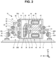
FIG. 2 illustrates a cross-sectional view along line II-II ofFIG. 1 ; -
FIG. 3 illustrates a cross-sectional view similar toFIG. 2 of adriving device 10A of a second example; -
FIG. 4 illustrates a plan view of adriving device 10B of a third example; -
FIG. 5 illustrates a plan view of adriving device 10C of a fourth example; and -
FIG. 6 illustrates a cross-sectional view similar toFIG. 2 of adriving device 10D of a fifth example. - In an embodiment of the present technology, the casing may accommodate the electric motor and the gear. However, in another embodiment, the casing may not accommodate the gear, for example.
- In an embodiment of the present technology, the casing may include a first casing that accommodates the electric motor and a second casing that accommodates the gear. However, in another embodiment, for example, the first casing may accommodate the electric motor and the gear.
- In an embodiment of the present technology, the high voltage component, the electric motor, and the gear may be arranged in this order along an axial direction parallel to a rotation axis of the electric motor. However, in another embodiment, the high voltage component, the electric motor, and the gear may be arranged in this order along the axial direction parallel to the rotation axis of the electric motor, or they may be arranged along the axial direction parallel to the rotation axis of the electric motor in order of the electric motor, the high voltage component, and the gear.
- In an embodiment of the present technology, the constituent member may include at least one of a vehicle body of the vehicle, a member fixed to the vehicle body, and a vibration generating member. In this case, the cover may be connected to the constituent member via a bracket. With such a configuration, for example, it is possible to suppress transmission of vibrations, whether caused by traveling of the vehicle or originating from the vibration generating member, to the high voltage component through the bracket.
- In an embodiment of the present technology, the vehicle may include a subframe fixed to the vehicle body, and the constituent member may include a supporting mount provided on the subframe. With such a configuration, it is possible to suppress transmission of vibration of the supporting mount provided on the subframe to the high voltage component through a bracket.
- In an embodiment of the present technology, the vehicle may include a compressor for air conditioning, and the vibration generating member may be the compressor. With such a configuration, it is possible to suppress transmission of vibration of the compressor to the high voltage component through a bracket.
- In an embodiment of the present technology, the vehicle may be a hybrid vehicle including an engine fixed to a vehicle body. In this case, the electric motor and the engine may be arranged along an axial direction parallel to a rotation axis of the electric motor. However, in another embodiment, the engine and the motor may be arranged along a direction orthogonal to the rotation axis of the electric motor.
- In an embodiment of the present technology, the side wall of the casing may extend in a direction that intersects a rotation axis of the electric motor of the casing. In this case, the constituent member may face an outer surface of the side wall. However, in another embodiment, the side wall of the casing may extend along a rotation axis of the electric motor of the casing. In this case, the constituent member may face an outer surface of the side wall.
-
FIG. 1 illustrates a plan view of anelectric vehicle 100 equipped with a drivingdevice 10 of a first example. Theelectric vehicle 100 includes avehicle body 2, afront drive shaft 5F, a pair offront wheels 4F, arear drive shaft 5R, a pair ofrear wheels 4R, a battery pack 6, arear suspension member 8, and acompressor 70 in addition to the drivingdevice 10. For easy understanding,FIG. 1 illustrates thevehicle body 2 of theelectric vehicle 100 with a dashed line. Theelectric vehicle 100 in the present disclosure includes electric vehicles as well as fuel cell vehicles. In the coordinate system in the drawing, FR indicates the front of theelectric vehicle 100, UP indicates the top of theelectric vehicle 100, and LH indicates the left side of theelectric vehicle 100. In the following, "up", "down", "left", "right", "front", and "rear" are described based on the coordinate system in the drawings. - One
front wheel 4F is provided at one end of thefront drive shaft 5F, and the otherfront wheel 4F is provided at the other end of thefront drive shaft 5F. Also, onerear wheel 4R is provided at one end of therear drive shaft 5R, and the otherrear wheel 4R is provided at the other end of therear drive shaft 5R. - The driving
device 10 is located below a rear seat (not illustrated) of theelectric vehicle 100 and above therear suspension member 8. In a modification example, the drivingdevice 10 may be located below a board forming a bottom surface of a luggage space of theelectric vehicle 100. The drivingdevice 10 drives therear wheels 4R via therear drive shaft 5R of theelectric vehicle 100. The drivingdevice 10 includes acasing 11, aninverter unit 20, agear unit 30, and amotor unit 40. Theinverter unit 20 has aninverter 22. Thegear unit 30 has alink gear 32, acounter gear 33, and adifferential gear 34. Themotor unit 40 has amotor 42. - The battery pack 6 is arranged below a floor panel 9 (see
FIG. 2 ) of theelectric vehicle 100. The battery pack 6 supplies electric power to the drivingdevice 10. Thereby, the drivingdevice 10 drives therear wheels 4R. The drivingdevice 10 also functions as a generator. The battery pack 6 stores electric power supplied from the drivingdevice 10. Theinverter 22 is connected to the battery pack 6 by apower cable 7. Theinverter 22 converts direct current power of the battery pack 6 into alternating current power suitable for driving themotor 42. Thus, theinverter 22 is a high voltage component to which high voltage power is applied. Here, the term "high voltage" refers to an operating voltage range of above DC 60 V to DC 1500 V, or above AC 30 V (root mean square value) to AC 1000 V (root mean square value). A "high voltage component" in the present disclosure may typically be a component that is electrically connected to themotor 42 and has a function of controlling electric power supplied to themotor 42. In this case, a cable connected to themotor 42 does not correspond to the "high voltage component". In a modification example, the drivingdevice 10 may incorporate a DC/DC converter that boosts the direct current power of the battery pack 6 instead of, or in addition to, theinverter 22, for example. - The
compressor 70 is located in afront component 3 of theelectric vehicle 100. Thecompressor 70 is an air-conditioning compressor that adjusts the temperature of a vehicle cabin of theelectric vehicle 100. - An internal structure of the driving
device 10 will be described with reference toFIG. 2 . Thecasing 11 of the drivingdevice 10 is a rectangular box and forms a space for accommodating themotor 42 and a space for accommodating thelink gear 32, thecounter gear 33, and thedifferential gear 34 of thegear unit 30. Thecasing 11 has aleft side wall 14 at a left end. Theleft side wall 14 is an outer wall that separates the inside and outside of thecasing 11 and extends in the vertical direction. The drivingdevice 10 is fixed to therear suspension member 8 via a pair ofbrackets mounts rear suspension member 8 is fixed to an upper surface of thefloor panel 9 of thevehicle body 2 of theelectric vehicle 100. Therear suspension member 8 is a subframe of theelectric vehicle 100 formed by combining a plurality of frames. The supporting mounts 50L, 50R are members provided on therear suspension member 8. The supportingmount 50L is a member that connects therear suspension member 8 and thebracket 60L. The supportingmount 50R is a member that connects therear suspension member 8 and thebracket 60R. Thebrackets mounts left bracket 60L and the supportingmount 50L among these components. - The
motor 42 inside thecasing 11 is a so-called electric motor, and includes arotor 44 and astator core 46. Therotor 44 extends in the right and left direction along a rotation axis A1 of themotor 42. Therotor 44 is made of a magnetic material and accommodates a permanent magnet (not illustrated) inside. Therotor 44 has amotor shaft 47 extending in an axial direction (that is, right and left direction) parallel to the rotation axis A1. Themotor shaft 47 is rotatably supported by thecasing 11 via a pair ofbearings 49. - Also, as illustrated in
FIG. 2 , in the drivingdevice 10, theinverter unit 20, thegear unit 30, and themotor unit 40 are arranged in this order from the left side along an axial direction parallel to the rotation axis A1. Further, thegear unit 30 is located between themotor 42 and theinverter 22. In a modification example, a cooling unit which supplies, to theinverter unit 20, a heat transfer medium for cooling theinverter 22 of theinverter unit 20 may be interposed between theinverter unit 20 and thegear unit 30. That is, in a modification example, in addition to theunits units - By arranging the
units device 10 in the vertical direction can be reduced compared to a configuration in which theunits electric vehicle 100 can be enlarged. Also, theleft side wall 14 extends in a direction intersecting with the rotation axis A1. - The
stator core 46 has a cylindrical shape and extends in the right and left direction along the rotation axis A1. Thestator core 46 is located radially outside therotor 44. A gap is provided between thestator core 46 and therotor 44. Thestator core 46 is made of a magnetic material. Astator coil 48 is provided on thestator core 46. Thestator coil 48 is made of a conductive body and wound around an outer surface of thestator core 46. Thestator coil 48 of themotor unit 40 is electrically connected to theinverter 22 of theinverter unit 20. When the electric power of the battery pack 6 is supplied to thestator coil 48 through theinverter 22, a magnetic force is generated between thestator coil 48 and therotor 44. This causes therotor 44 to rotate around the rotation axis A1. - The
motor shaft 47 extends leftward from themotor unit 40 until it reaches thelink gear 32 of thegear unit 30. Themotor shaft 47 is connected to thelink gear 32 of thegear unit 30. That is, themotor 42 is mechanically connected to thelink gear 32 via themotor shaft 47. Thereby, rotation of therotor 44 of themotor 42 is transmitted to thelink gear 32. Thelink gear 32 meshes with thecounter gear 33. Thecounter gear 33 meshes with thedifferential gear 34. That is, thelink gear 32 is mechanically connected to thedifferential gear 34 via thecounter gear 33. Thedifferential gear 34 is mechanically connected to therear drive shaft 5R. Thereby, the rotation of thelink gear 32 is transmitted to therear drive shaft 5R via thecounter gear 33 and thedifferential gear 34. Thus, themotor 42 drives therear wheels 4R through the threegears gear unit 30. In a modification example, thegear unit 30 may not include thecounter gear 33, for example. In this case, thelink gear 32 and thedifferential gear 34 may mesh directly. - The
inverter unit 20 includes acover 21 in addition to theinverter 22. Theinverter 22 includes a plurality of switching elements. Theinverter 22 is fixed to theleft side wall 14 of thecasing 11 with a plurality of bolts B2 from the left side of thecasing 11. Theinverter 22 is fixed to theleft side wall 14 of thecasing 11 from the outside of thecasing 11. - The
cover 21 of theinverter unit 20 has a box shape with an open right side. Thecover 21 includes anend wall 24, anannular wall 23, and a pair offlanges end wall 24 extending in the vertical direction is connected to theflanges annular wall 23 extending in the right and left direction. After theinverter 22 is fixed to theleft side wall 14 of thecasing 11, thecover 21 is fixed to theleft side wall 14 around the left side of theinverter 22. As a result, thecover 21 covers theinverter 22 from the left side. Theinverter 22 is fixed to theleft side wall 14 of thecasing 11 via theflanges casing 11. Thecasing 11 may further accommodate a smoothing capacitor for smoothing the output of theinverter 22 and/or a filter for suppressing noise from occurring in the input of theinverter 22. - The
bracket 60L is fixed to theend wall 24 of thecover 21 with a plurality of bolts B1. Thebracket 60L includes a fixing portion that abuts theend wall 24 of thecover 21, and a body portion bent into an L shape. A boss of the supportingmount 50L is inserted into a lower end portion of the body portion of thebracket 60L. Thereby, thebracket 60L is fixed to the supportingmount 50L. As a result, as illustrated inFIG. 2 , a left side surface of theleft side wall 14 faces the supportingmount 50L. In a modification example, thebracket 60L may be fixed to theend wall 24 of thecover 21 with an adhesive or by welding. - As an example, when the
electric vehicle 100 travels, the vehicle body 2 (for example, floor panel 9) vibrates. In this case, vibration of thefloor panel 9 is transmitted to the drivingdevice 10 via therear suspension member 8, the supportingmounts brackets inverter 22, which is a high voltage component. Theinverter 22 is covered with thecover 21, and thecover 21 is fixed to therear suspension member 8 via the supportingmount 50L and thebracket 60L. Therefore, the vibration of the supportingmount 50L is transmitted through thebracket 60L to thecover 21 covering theinverter 22. - In the driving
device 10, theinverter 22 is fixed to theleft side wall 14 of thecasing 11 from the outside of thecasing 11. That is, theinverter 22 is not directly fixed to thecover 21 that covers theinverter 22. Therefore, even when vibration is transmitted from the supportingmount 50L to thecover 21, the vibration is not directly transmitted from thecover 21 to theinverter 22. The vibration is first transmitted to theleft side wall 14 of thecasing 11 and transmitted to theinverter 22 after being damped by theleft side wall 14. Thus, according to the drivingdevice 10 of the present embodiment, compared to the technology of the related art in which theinverter 22 is directly fixed to thecover 21, vibration transmitted from the supportingmount 50L to theinverter 22 can be reduced. - A driving
device 10A of a second example will be described with reference toFIG. 3 . The drivingdevice 10A of the second example differs in the arrangement of themotor unit 40 and thegear unit 30 from the drivingdevice 10 of the first example. Specifically, in thedriving device 10A of the second example, theinverter unit 20, themotor unit 40, and thegear unit 30 are arranged in this order from the left side along an axial direction (that is, right and left direction) parallel to the rotation axis A1. Further, in thedriving device 10A of the present example, themotor 42 is located between thegear unit 30 and theinverter 22. Also, in thedriving device 10A of the present example, theinverter 22 is fixed to theleft side wall 14 of thecasing 11 from the outside of thecasing 11. Therefore, similarly to the drivingdevice 10 of the first example, vibration transmitted from the supportingmount 50L to theinverter 22 can be reduced. In the second example, in addition to theunits units - A driving
device 10B of a third example will be described with reference toFIG. 4. FIG. 4 illustrates a plan view of thedriving device 10B of the third example. Thedriving device 10B of the third example is arranged in a front component 3 (seeFIG. 1 ) of an electric vehicle 100B unlike the drivingdevice 10 of the first example. A drivingdevice 10B of the third example includes amotor unit 40F and agear unit 30F, and drives thefront wheels 4F (seeFIG. 1 ) via thefront drive shaft 5F. Themotor unit 40F has amotor 42F, and thegear unit 30F has a link gear 32F and a differential gear 34F. The structure of themotor unit 40F is similar to that of themotor unit 40 of the first example. The structure of thegear unit 30F is similar to that of thegear unit 30 of the first example. - The
driving device 10B of the third example is fixed to a floor surface of thefront component 3, that is, afloor panel 9C by aleft mount 52L, aleft bracket 62L, the bolts B1, and a plurality of bolts B3 from the left side. Further, the drivingdevice 10B of the present example is fixed to thefloor panel 9C by aright mount 52R, aright bracket 62R, the bolts B1, and the bolts B3 from the right side. - In the
driving device 10B of the third example, aninverter unit 20F is arranged in front of thedriving device 10B. That is, theinverter unit 20F is not arranged along an axial direction parallel to themotor unit 40F, thegear unit 30F, and a rotation axis A2 of themotor 42F. Theinverter unit 20F is fixed by the bolts B2 to afront wall 14F of acasing 11F of thedriving device 10B. Thefront wall 14F extends along the rotation axis A2 of themotor 42F, unlike theleft side wall 14 of the first example. - Further, in the
driving device 10B of the third example, unlike the drivingdevice 10 of the first example described above, thefront wall 14F is composed of a casing of themotor unit 40F and a casing of thegear unit 30F. Therefore, theinverter unit 20 is fixed to thefront wall 14F across themotor unit 40F and thegear unit 30F. - Further, the
compressor 70 is fixed to acover 21F by abracket 64F and the bolts B1. Thecompressor 70 is located in front of thedriving device 10B. Thecompressor 70 faces a front surface of thefront wall 14F. - The
compressor 70 compresses and expands the heat medium by reciprocating a piston (not illustrated). Therefore, thecompressor 70 is a vibration generating member that generates vibration when operated. - As illustrated in
FIG. 4 , in thedriving device 10B of the present example, thecompressor 70 is connected to thecover 21F via thebracket 64F. Therefore, the vibration of thecompressor 70 is transmitted to thedriving device 10B through thebracket 64F. However, in thedriving device 10B, aninverter 22F of theinverter unit 20F is fixed not to thecover 21F but to thefront wall 14F of thecasing 11F by the bolts B2. Therefore, the vibration transmitted from thecompressor 70 to theinverter 22F can be reduced compared to the technology of the related art in which theinverter 22F is fixed to thecover 21F. Also, by fixing thecompressor 70 to thedriving device 10B via thebracket 64F, it is possible to reduce restrictions on layout of devices accommodated in thefront component 3. - A driving
device 10C of a fourth example will be described with reference toFIG. 5 . The drivingdevice 10C of the fourth example is arranged in afront component 3C of ahybrid vehicle 100C, unlike the drivingdevices hybrid vehicle 100C includes anengine 80. - Also, unlike the
driving device 10B of the third example, the drivingdevice 10C of the present example does not have thegear unit 30F. Therefore, amotor 42C of amotor unit 40C is directly connected to thefront drive shaft 5F inside acasing 11C. Further, theengine 80 is arranged on the left side of thedriving device 10C. That is, themotor 42C and theengine 80 are arranged along an axial direction (that is, right and left direction) parallel to a rotation axis A3 of themotor 42C. In addition, in a modification example, a gear unit may be provided between themotor unit 40C and theengine 80. - Further, an accommodation space S1 is provided in a front part of the
casing 11C of thedriving device 10C of the present example. The accommodation space S1 is a recess provided in the front part of thecasing 11C, and the front is open. Abottom wall 14C of the accommodation space S 1 extends in the right and left direction along the rotation axis A3 of themotor 42C. - An
inverter 22C is arranged in the accommodation space S 1. Theinverter 22C is fixed to thebottom wall 14C of the accommodation space S1 by the bolts B2 from the front side of thebottom wall 14C. Further, thecover 21C is fixed to a front surface of thecasing 11C by the bolts B2. Thecover 21C is a flat board member extending parallel to thebottom wall 14C of the accommodation space S 1. Thecover 21C is a lid that closes the accommodation space S1. Thecover 21C covers theinverter 22C arranged in the accommodation space S1. - The
cover 21C is fixed to a floor surface of thefront component 3C, that is, afloor panel 9C via abracket 64C. Further, theengine 80 is fixed to thefloor panel 9C by aleft bracket 62L the bolts B1, and the bolts B3 from the left side. The drivingdevice 10C is fixed to thefloor panel 9C by aright bracket 62R, the bolts B1, and the bolts B3 from the right side. - Thus, the driving
device 10C of the present example is fixed to thefloor panel 9C by a pair ofbrackets floor panel 9C by thebracket 64C from the front. Therefore, the drivingdevice 10C is fixed to thefloor panel 9C more firmly than in a configuration in which thedriving device 10C is fixed only in the right and left direction. - Also, vibration of the
floor panel 9C is transmitted to thecover 21C via thebracket 64C. However, in thedriving device 10C, theinverter 22C is fixed not to thecover 21C but to thebottom wall 14C of the accommodation space S1 of thecasing 11C by the bolts B2. Therefore, the vibration transmitted from thefloor panel 9C to theinverter 22C can be reduced as compared with the technology of the related art in which theinverter 22C is fixed to thecover 21C. In the present example, thefloor panel 9C is an example of a "constituent member". - A
driving device 10D of a fifth example will be described with reference toFIG. 6 . Thedriving device 10D of the fifth example differs from the drivingdevice 10A of the second example in the configuration of thecasing 11D. Thecasing 11D of thedriving device 10D of the present example has amotor casing 15D and agear casing 12D. Themotor casing 15D accommodates themotor 42. In addition to aleft side wall 14D, themotor casing 15D further has anextension wall 16D extending leftward beyond theleft side wall 14D. Theextension wall 16D covers theinverter 22 of theinverter unit 20 from above and below. An opening 17D is provided at a left end of themotor casing 15D. The opening 17D allows communication between the inside of thecasing 11D in which theinverter 22 is accommodated and the outside of thecasing 11D. - The opening 17D of the
motor casing 15D is covered with acover 21D. That is, thecover 21D covers theinverter 22. Thecover 21D has aseat portion 28D extending leftward. Theseat portion 28D is fixed to a supportingmount 54L by bolts B4. Thus, thecover 21D of the present example is fixed to the supportingmount 54L via theseat portion 28D of thecover 21D. In a modification example, thecover 21D may be directly fixed to the supportingmount 54L or fixed to thevehicle body 2 without passing through theseat portion 28D. - The
gear casing 12D is fixed to themotor casing 15D with a plurality of bolts B5. That is, thegear casing 12D and themotor casing 15D are fastened together. Further, a sealingmember 19 is provided at the boundary between thecasings member 19 may be, for example, an O-ring. By utilizing the sealingmember 19 to seal a space inside thegear casing 12D, it is possible to prevent a lubricant used for smooth rotation of each of thegears gear casing 12D. Thus, in the present example, thecasing 11D is composed of two casings, thegear casing 12D and themotor casing 15D. That is, in the present example, themotor casing 15D is an example of the "first casing", and thegear casing 12D is an example of the "second casing". In a modification example,casings - Like the
cover 21D, thegear casing 12D also has aseat portion 13D. Theseat portion 13D is fixed to the supportingmount 54R with the bolts B4. Also, in thedriving device 10D of the present example, theinverter 22 is fixed to theleft side wall 14D of themotor casing 15D from the outside. Therefore, similarly to the drivingdevice 10 of the first example, vibration transmitted from the supportingmount 54L to theinverter 22 can be reduced. - Although specific examples according to the technology of the present disclosure are described above in detail, these are merely examples and do not limit the scope of the claims. The technology described in the claims includes various modifications and changes of the specific examples illustrated above.
- The technical elements described in the present disclosure exhibit technical utility either alone or in various combinations, and are not limited to the combinations described in the claims as of the filing. In addition, the technology exemplified in the present disclosure can achieve multiple purposes at the same time, and achieving one of them has technical utility in itself.
Claims (13)
- A driving device (10), comprising:an electric motor (42) configured to drive a wheel of a vehicle;a gear (32) connected to the electric motor (42);a casing (11) accommodating at least one of the electric motor (42) and the gear (32);a high voltage component (22) fixed to a side wall of the casing (11) from outside of the casing (11) and electrically connected to the electric motor (42); anda cover (21) fixed to the side wall of the casing (11) from outside of the casing (11) and covering the high voltage component (22), whereinthe cover (21) is configured to be connected to a constituent member located outside the cover (21).
- The driving device (10) according to claim 1, wherein the casing (11) accommodates the electric motor (42) and the gear (32).
- The driving device (10) according to claim 1, wherein the casing (11) has a first casing that accommodates the electric motor (42) and a second casing that accommodates the gear (32).
- The driving device (10) according to claim 2 or 3, wherein the high voltage component (22), the electric motor (42), and the gear (32) are arranged in order of the high voltage component (22), the electric motor, and the gear (32) along an axial direction parallel to a rotation axis of the electric motor (42).
- The driving device (10) according to claim 2 or 3, wherein the high-voltage component (22), the electric motor (42), and the gear (32) are arranged in order of the high voltage component (22), the gear (32), and the electric motor (42) along an axial direction parallel to a rotation axis of the electric motor (42).
- The driving device (10) according to claim 1, wherein:the constituent member includes at least one of a vehicle body of the vehicle, a member fixed to the vehicle body, and a vibration generating member; andthe cover (21) is configured to be connected to the constituent member through a bracket.
- The driving device (10) according to claim 6, wherein:the vehicle includes a subframe fixed to the vehicle body; andthe constituent member includes a supporting mount provided in the subframe.
- The driving device (10) according to claim 6, wherein:the vehicle includes a compressor for air conditioning; andthe vibration generating member includes the compressor.
- The driving device (10) according to claim 1, wherein:the vehicle is a hybrid vehicle including an engine fixed to a vehicle body; andthe electric motor (42) and the engine are arranged along an axial direction parallel to a rotation axis of the electric motor (42).
- The driving device (10) according to claim 1, wherein:the side wall of the casing (11) extends in a direction intersecting with a rotation axis of the electric motor (42) of the casing (11); andthe constituent member faces an outer surface of the side wall.
- The driving device (10) according to claim 1, wherein:the side wall of the casing (11) extends along a rotation axis of the electric motor (42) of the casing (11); andthe constituent member faces an outer surface of the side wall.
- The driving device (10) according to claim 1, wherein the high voltage component (22) is an inverter or/and a DC/DC converter.
- The driving device (10) according to claim 1, wherein the high voltage component (22) is a component with an operating voltage range above DC 60 V to DC 1500 V, or above AC 30 V to AC 1000 V in root mean square value.
Applications Claiming Priority (1)
| Application Number | Priority Date | Filing Date | Title |
|---|---|---|---|
| JP2022201388A JP7782435B2 (en) | 2022-12-16 | 2022-12-16 | Drive unit |
Publications (1)
| Publication Number | Publication Date |
|---|---|
| EP4385778A1 true EP4385778A1 (en) | 2024-06-19 |
Family
ID=89164440
Family Applications (1)
| Application Number | Title | Priority Date | Filing Date |
|---|---|---|---|
| EP23215126.6A Pending EP4385778A1 (en) | 2022-12-16 | 2023-12-08 | Driving device |
Country Status (5)
| Country | Link |
|---|---|
| US (1) | US20240198781A1 (en) |
| EP (1) | EP4385778A1 (en) |
| JP (1) | JP7782435B2 (en) |
| KR (1) | KR20240095011A (en) |
| CN (1) | CN118214210A (en) |
Citations (4)
| Publication number | Priority date | Publication date | Assignee | Title |
|---|---|---|---|---|
| US20150224884A1 (en) * | 2014-02-08 | 2015-08-13 | Atieva, Inc. | Integrated Motor Assembly with Compliantly Mounted Power Inverter |
| US9692277B2 (en) | 2010-12-17 | 2017-06-27 | Tesla, Inc. | Integrated electric motor assembly |
| US10744863B2 (en) * | 2018-03-13 | 2020-08-18 | Honda Motor Co., Ltd. | Power unit structure for electrically driven vehicle |
| GB2590382A (en) * | 2019-12-13 | 2021-06-30 | Dyson Technology Ltd | Electric drive unit |
Family Cites Families (6)
| Publication number | Priority date | Publication date | Assignee | Title |
|---|---|---|---|---|
| JP2000297641A (en) * | 1999-04-12 | 2000-10-24 | Hitachi Ltd | Cooling device for vehicle drive system |
| JP2001119898A (en) * | 1999-10-18 | 2001-04-27 | Aisin Aw Co Ltd | Driver |
| JP2004187437A (en) * | 2002-12-05 | 2004-07-02 | Nissan Motor Co Ltd | Motor drive unit |
| JP2020089165A (en) * | 2018-11-29 | 2020-06-04 | 株式会社デンソー | Vehicle power transmission device |
| JP6997245B2 (en) * | 2020-03-31 | 2022-01-17 | 本田技研工業株式会社 | Rotary machine drive unit |
| JP2022159657A (en) * | 2021-04-05 | 2022-10-18 | トヨタ自動車株式会社 | Mount structure of drive unit for electric vehicle |
-
2022
- 2022-12-16 JP JP2022201388A patent/JP7782435B2/en active Active
-
2023
- 2023-11-28 KR KR1020230167643A patent/KR20240095011A/en active Pending
- 2023-11-29 CN CN202311617740.5A patent/CN118214210A/en active Pending
- 2023-12-08 EP EP23215126.6A patent/EP4385778A1/en active Pending
- 2023-12-13 US US18/538,205 patent/US20240198781A1/en active Pending
Patent Citations (4)
| Publication number | Priority date | Publication date | Assignee | Title |
|---|---|---|---|---|
| US9692277B2 (en) | 2010-12-17 | 2017-06-27 | Tesla, Inc. | Integrated electric motor assembly |
| US20150224884A1 (en) * | 2014-02-08 | 2015-08-13 | Atieva, Inc. | Integrated Motor Assembly with Compliantly Mounted Power Inverter |
| US10744863B2 (en) * | 2018-03-13 | 2020-08-18 | Honda Motor Co., Ltd. | Power unit structure for electrically driven vehicle |
| GB2590382A (en) * | 2019-12-13 | 2021-06-30 | Dyson Technology Ltd | Electric drive unit |
Also Published As
| Publication number | Publication date |
|---|---|
| JP7782435B2 (en) | 2025-12-09 |
| JP2024086318A (en) | 2024-06-27 |
| KR20240095011A (en) | 2024-06-25 |
| US20240198781A1 (en) | 2024-06-20 |
| CN118214210A (en) | 2024-06-18 |
Similar Documents
| Publication | Publication Date | Title |
|---|---|---|
| CN101296814B (en) | Drive apparatus for hybrid vehicle | |
| CN107206884B (en) | Drive unit for hybrid vehicle | |
| CN109515143B (en) | electric vehicle | |
| CN114342227A (en) | Vehicle drive device | |
| JP6256234B2 (en) | Electric vehicle | |
| WO2009133752A1 (en) | Drive device | |
| JP2007050887A (en) | Power control unit for vehicles | |
| US7963353B2 (en) | Power output device of hybrid vehicle | |
| JP2019055765A (en) | Electric vehicle | |
| US20230039195A1 (en) | Motor unit and electric car | |
| JP2024096932A (en) | Vehicle drive device | |
| EP4385778A1 (en) | Driving device | |
| JP2021044987A (en) | Vehicle drive unit | |
| US20240416740A1 (en) | Powertrain structure of vehicle | |
| JP7732407B2 (en) | Vehicle drive unit | |
| US20240039365A1 (en) | Vehicle drive device | |
| US20240239177A1 (en) | Drive unit | |
| US20240286482A1 (en) | Electrified vehicle | |
| JP7816205B2 (en) | Drive unit | |
| CN223666125U (en) | Power assembly and electric vehicle | |
| US20250214408A1 (en) | Mounting structure for electrical device | |
| JP7793901B2 (en) | Vehicle drive unit | |
| EP4477437A1 (en) | Powertrain structure of vehicle and vehicle | |
| JP2020104603A (en) | Electric car | |
| EP4518109A2 (en) | Vehicle drive device |
Legal Events
| Date | Code | Title | Description |
|---|---|---|---|
| PUAI | Public reference made under article 153(3) epc to a published international application that has entered the european phase |
Free format text: ORIGINAL CODE: 0009012 |
|
| STAA | Information on the status of an ep patent application or granted ep patent |
Free format text: STATUS: REQUEST FOR EXAMINATION WAS MADE |
|
| 17P | Request for examination filed |
Effective date: 20231208 |
|
| AK | Designated contracting states |
Kind code of ref document: A1 Designated state(s): AL AT BE BG CH CY CZ DE DK EE ES FI FR GB GR HR HU IE IS IT LI LT LU LV MC ME MK MT NL NO PL PT RO RS SE SI SK SM TR |