EP4385702B1 - Verfahren zur herstellung einer platte - Google Patents
Verfahren zur herstellung einer platte Download PDFInfo
- Publication number
- EP4385702B1 EP4385702B1 EP23214722.3A EP23214722A EP4385702B1 EP 4385702 B1 EP4385702 B1 EP 4385702B1 EP 23214722 A EP23214722 A EP 23214722A EP 4385702 B1 EP4385702 B1 EP 4385702B1
- Authority
- EP
- European Patent Office
- Prior art keywords
- foil
- polyisocyanurate foam
- liquid
- foam formulation
- spraying
- Prior art date
- Legal status (The legal status is an assumption and is not a legal conclusion. Google has not performed a legal analysis and makes no representation as to the accuracy of the status listed.)
- Active
Links
Images
Classifications
-
- B—PERFORMING OPERATIONS; TRANSPORTING
- B29—WORKING OF PLASTICS; WORKING OF SUBSTANCES IN A PLASTIC STATE IN GENERAL
- B29C—SHAPING OR JOINING OF PLASTICS; SHAPING OF MATERIAL IN A PLASTIC STATE, NOT OTHERWISE PROVIDED FOR; AFTER-TREATMENT OF THE SHAPED PRODUCTS, e.g. REPAIRING
- B29C35/00—Heating, cooling or curing, e.g. crosslinking or vulcanising; Apparatus therefor
- B29C35/007—Tempering units for temperature control of moulds or cores, e.g. comprising heat exchangers, controlled valves, temperature-controlled circuits for fluids
-
- B—PERFORMING OPERATIONS; TRANSPORTING
- B29—WORKING OF PLASTICS; WORKING OF SUBSTANCES IN A PLASTIC STATE IN GENERAL
- B29C—SHAPING OR JOINING OF PLASTICS; SHAPING OF MATERIAL IN A PLASTIC STATE, NOT OTHERWISE PROVIDED FOR; AFTER-TREATMENT OF THE SHAPED PRODUCTS, e.g. REPAIRING
- B29C44/00—Shaping by internal pressure generated in the material, e.g. swelling or foaming ; Producing porous or cellular expanded plastics articles
- B29C44/20—Shaping by internal pressure generated in the material, e.g. swelling or foaming ; Producing porous or cellular expanded plastics articles for articles of indefinite length
- B29C44/28—Expanding the moulding material on continuous moving surfaces without restricting the upwards growth of the foam
-
- B—PERFORMING OPERATIONS; TRANSPORTING
- B29—WORKING OF PLASTICS; WORKING OF SUBSTANCES IN A PLASTIC STATE IN GENERAL
- B29C—SHAPING OR JOINING OF PLASTICS; SHAPING OF MATERIAL IN A PLASTIC STATE, NOT OTHERWISE PROVIDED FOR; AFTER-TREATMENT OF THE SHAPED PRODUCTS, e.g. REPAIRING
- B29C44/00—Shaping by internal pressure generated in the material, e.g. swelling or foaming ; Producing porous or cellular expanded plastics articles
- B29C44/20—Shaping by internal pressure generated in the material, e.g. swelling or foaming ; Producing porous or cellular expanded plastics articles for articles of indefinite length
- B29C44/32—Incorporating or moulding on preformed parts, e.g. linings, inserts or reinforcements
- B29C44/321—Incorporating or moulding on preformed parts, e.g. linings, inserts or reinforcements the preformed part being a lining, e.g. a film or a support lining
-
- B—PERFORMING OPERATIONS; TRANSPORTING
- B29—WORKING OF PLASTICS; WORKING OF SUBSTANCES IN A PLASTIC STATE IN GENERAL
- B29C—SHAPING OR JOINING OF PLASTICS; SHAPING OF MATERIAL IN A PLASTIC STATE, NOT OTHERWISE PROVIDED FOR; AFTER-TREATMENT OF THE SHAPED PRODUCTS, e.g. REPAIRING
- B29C44/00—Shaping by internal pressure generated in the material, e.g. swelling or foaming ; Producing porous or cellular expanded plastics articles
- B29C44/20—Shaping by internal pressure generated in the material, e.g. swelling or foaming ; Producing porous or cellular expanded plastics articles for articles of indefinite length
- B29C44/32—Incorporating or moulding on preformed parts, e.g. linings, inserts or reinforcements
- B29C44/326—Joining the preformed parts, e.g. to make flat or profiled sandwich laminates
-
- B—PERFORMING OPERATIONS; TRANSPORTING
- B29—WORKING OF PLASTICS; WORKING OF SUBSTANCES IN A PLASTIC STATE IN GENERAL
- B29C—SHAPING OR JOINING OF PLASTICS; SHAPING OF MATERIAL IN A PLASTIC STATE, NOT OTHERWISE PROVIDED FOR; AFTER-TREATMENT OF THE SHAPED PRODUCTS, e.g. REPAIRING
- B29C44/00—Shaping by internal pressure generated in the material, e.g. swelling or foaming ; Producing porous or cellular expanded plastics articles
- B29C44/34—Auxiliary operations
- B29C44/3415—Heating or cooling
-
- B—PERFORMING OPERATIONS; TRANSPORTING
- B29—WORKING OF PLASTICS; WORKING OF SUBSTANCES IN A PLASTIC STATE IN GENERAL
- B29C—SHAPING OR JOINING OF PLASTICS; SHAPING OF MATERIAL IN A PLASTIC STATE, NOT OTHERWISE PROVIDED FOR; AFTER-TREATMENT OF THE SHAPED PRODUCTS, e.g. REPAIRING
- B29C44/00—Shaping by internal pressure generated in the material, e.g. swelling or foaming ; Producing porous or cellular expanded plastics articles
- B29C44/34—Auxiliary operations
- B29C44/36—Feeding the material to be shaped
- B29C44/46—Feeding the material to be shaped into an open space or onto moving surfaces, i.e. to make articles of indefinite length
- B29C44/461—Feeding the material to be shaped into an open space or onto moving surfaces, i.e. to make articles of indefinite length dispensing apparatus, e.g. dispensing foaming resin over the whole width of the moving surface
-
- B—PERFORMING OPERATIONS; TRANSPORTING
- B29—WORKING OF PLASTICS; WORKING OF SUBSTANCES IN A PLASTIC STATE IN GENERAL
- B29C—SHAPING OR JOINING OF PLASTICS; SHAPING OF MATERIAL IN A PLASTIC STATE, NOT OTHERWISE PROVIDED FOR; AFTER-TREATMENT OF THE SHAPED PRODUCTS, e.g. REPAIRING
- B29C63/00—Lining or sheathing, i.e. applying preformed layers or sheathings of plastics; Apparatus therefor
- B29C63/0026—Lining or sheathing, i.e. applying preformed layers or sheathings of plastics; Apparatus therefor an edge face with strip material, e.g. a panel edge
-
- B—PERFORMING OPERATIONS; TRANSPORTING
- B29—WORKING OF PLASTICS; WORKING OF SUBSTANCES IN A PLASTIC STATE IN GENERAL
- B29L—INDEXING SCHEME ASSOCIATED WITH SUBCLASS B29C, RELATING TO PARTICULAR ARTICLES
- B29L2007/00—Flat articles, e.g. films or sheets
- B29L2007/002—Panels; Plates; Sheets
Definitions
- WO2022/047102 describes a method for producing an insulation panel made of polyisocyanurate.
- EP1790452A2 discloses a rigid polymeric insulating foam board comprises an upper facing, a lower facing and a foam layer between the upper and the lower facing.
- the foam sandwich is delivered into an oven and the continuous length of foam board exiting the oven is delivered through a curing station.
- the foam board is cut to length, trimmed, optimally re-bated, the cut board lengths are stacked and wrapped .
- a cooling station for the wrapped stacks comprises upper and lower stack conveyors.
- Scissors-type lifters are provided at the infeed and outfeed end to divert a stack to or from a cooling conveyor 51.
- the invention relates to a method for producing a polyisocyanurate (PIR) insulation panel on a production line, wherein the produced insulation panel comprises a polyisocyanurate foam between two foils.
- the method is characterized in that the method comprises the step in which a liquid polyisocyanurate foam formulation is deposited on a foil, so that, at the position where the liquid polyisocyanurate foam formulation is deposited on the foil, the foil is moistened in an uninterrupted manner by the liquid polyisocyanurate foam formulation in the direction at right angles to the direction of production; and in that, at the position where the liquid foam formulation is deposited on the foil, the foil is supported by a heated table, wherein, in the method, the liquid polyisocyanurate foam formulation reacts to form a polyisocyanurate foam which is bonded to the foil.
- An aesthetically more pleasing polyisocyanurate insulation panel is obtained by depositing the liquid polyisocyanurate foam formulation on a foil, so that the foil, at the position where the liquid foam formulation is deposited on the foil, is moistened in an uninterrupted manner in the direction at right angles to the direction of production; and because the foil is supported by a heated table at the position where the liquid foam formulation is deposited on the foil.
- insulation panels with a higher compressive strength in the thickness direction of the insulation panel are obtained. Since the polyisocyanurate foam on the production line can only expand in a vertical direction, the cells in the polyisocyanurate foam are oriented mainly in the thickness direction of the insulation panel. This ensures an improved compressive strength in the thickness direction of the insulation panel.
- the foil may continuously be passed through the production line in the direction of production of the polyisocyanurate panel. This ensures a continuous production process for producing polyisocyanurate (PIR) insulation panels.
- PIR polyisocyanurate
- a preferred embodiment is characterized in that the heated table is arranged in a fixed position. This results in a simple design.
- the foil - with the liquid foam on top thereof - can be pushed across this heated table which is arranged in a fixed position.
- a preferred embodiment of the method is characterized in that, at the position where the liquid polyisocyanurate foam formulation is deposited on the foil, the heated table has a temperature of at least 30°C, and preferably of less than 50°C, and more preferably of at least 35°C.
- the foil with the polyisocyanurate foam on top thereof is passed through an oven downstream of the heated table by means of and between a double belt.
- the reactants in the polyisocyanurate foam can continue to react, so that the rigid foam of the polyisocyanurate insulation panel is formed correctly.
- the heated table comprises at least three sections in the direction of production; and more preferably at least five sections; and even more preferably at least six sections.
- the temperature in these sections can be adjusted separately.
- the method uses sensors and control circuits to measure and control the temperature in each of these sections with respect to the desired temperature in the respective section.
- these three subsections comprise a central section and two edge sections, wherein the central section is at least double the width of each of the two edge sections. This is advantageous since edge effects might occur along the edges during the production of the insulation panel. Control of the temperature in these edge sections of the heated table makes is possible to reduce edge effects or even to prevent them altogether.
- each spraying unit comprises a number of spraying ducts, placed at right angles to the transverse distribution duct, wherein each spraying duct passes a separate stream of the liquid polyisocyanurate foam formulation from the transverse distribution duct to a spray nozzle, wherein the length of the spraying ducts decreases from spraying ducts which end in a centrally positioned spray nozzle or the centrally positioned spray nozzles, to the spraying ducts which end in the most distal spray nozzles with respect to the central supply duct.
- Such embodiments have the advantage that an equal amount of liquid polyisocyanurate foam formulation flows from the various spray nozzles of the spraying unit. This ensures good uniformity of the insulation panel.
- This embodiment has the advantage that an equal amount of liquid polyisocyanurate foam formulation flows from the various spray nozzles of the spraying unit. This ensures good uniformity of the insulation panel.
- the second transverse distribution duct ensures that an equal amount of liquid polyisocyanurate foam formulation flows from the various spray nozzles.
- each case two connecting ducts are arranged symmetrically with respect to the central supply duct. This ensures an even better uniform distribution of the liquid polyisocyanurate foam formulation across the various spray nozzles of the spraying unit.
- each spraying unit comprises at least ten, and preferably at least twelve spray nozzles. This number ensures a precise distribution of the liquid polyisocyanurate foam formulation.
- each spraying unit is composed of one or more plastic injection-moulded parts.
- the spray nozzles are oriented in such a way that the liquid polyisocyanurate foam formulation flows vertically from the spray nozzles in the direction of the foil. This allows for an efficient deposition of the liquid polyisocyanurate foam formulation on the foil.
- a preferred embodiment of the invention is characterized in that, upstream of the oven, a second foil is supplied above the foil with the polyisocyanurate foam on top thereof.
- the foil with the polyisocyanurate foam on top thereof and the second foil are passed through the oven by means of and between a double belt.
- the liquid polyisocyanurate foam formulation expands and reacts to form a polyisocyanurate foam bonded to and situated between the foil and the second foil.
- the vertical position of the running in of the second foil is determined by the fact that the second foil is passed under a roller, wherein the vertical position of this roller is controlled by means of a control circuit depending on a measurement of the height of the polyisocyanurate foam upstream of the position of the roller.
- the height measurement across the width is performed by means of an optical measurement, more preferably a laser is used for this purpose.
- the foil is a laminate, wherein the laminate comprises:
- Such embodiments make it possible to produce high-quality polyisocyanurate insulation panels using the method of the invention.
- the combination of the polyester polyol and the polymeric methylene diphenyl diisocyanate constitutes at least 85% by weight - and more preferably at least 90% by weight - of the liquid polyisocyanurate (PIR) foam formulation.
- PIR liquid polyisocyanurate
- the liquid polyisocyanurate foam formulation has a viscosity, measured at 25°C, of between 165 and 950 mPa.s.
- a viscosity measured at 25°C
- Such embodiments are advantageous because they further facilitate the complete moisturisation of the foil with the liquid polyisocyanurate foam formulation in the direction at right angles to the direction of production in an uninterrupted manner.
- a paper strip 55 is introduced next to the foil on both sides of the foil 14.
- the paper strip 55 is attached to the foil 14 on both sides by means of adhesive tape 57.
- the paper strips 55 are folded on both sides to a vertical position in the production line, wherein the polyisocyanurate foam bonds to these vertical paper strips. These paper strips 55 form the lateral edges of the produced polyisocyanurate insulation panel.
- the liquid polyisocyanurate foam formulation may flow from the spray nozzles 41 at right angles to the direction of production of the polyisocyanurate panel. This is illustrated in Fig. 2 .
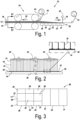
- the spraying unit 43 from Fig. 5 comprises a number of spraying ducts 48, placed at right angles to the transverse distribution duct 47. Each spraying duct 48 passes a separate stream of the liquid polyisocyanurate foam formulation from the transverse distribution duct 47 to a spray nozzle 41.
- the length of the spraying ducts 48 decreases from spraying ducts which end in a centrally positioned spray nozzle or the centrally positioned spray nozzles, to the spraying ducts 48 which end in the most distal spray nozzles 41 with respect to the central supply duct 45.
- the twelve spray nozzles 41 of the spraying unit from Fig. 5 are circular.
- the spraying unit from Fig. 5 is composed of plastic injection-moulded parts.
- Spraying units 43 as shown in Fig. 5 are preferably used for producing insulation panels having a thickness of 60 mm or less.
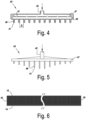
- Fig. 6 shows a polyisocyanurate insulation panel as may be produced according to the method of the invention.
- the insulation panel comprises a rigid polyisocyanurate foam 12 between two foils 14, 16.
- the sides are formed by paper strips 55.
- These polyisocyanurate insulation panels are produced in full width on a production line as shown in Fig. 1 , in the example from Fig. 1 in a width of 1200 mm. If required, insulation panels may then be sawn to size from these insulation panels which are 1200 mm wide.
Landscapes
- Engineering & Computer Science (AREA)
- Manufacturing & Machinery (AREA)
- Mechanical Engineering (AREA)
- Physics & Mathematics (AREA)
- Health & Medical Sciences (AREA)
- Oral & Maxillofacial Surgery (AREA)
- Thermal Sciences (AREA)
- Casting Or Compression Moulding Of Plastics Or The Like (AREA)
- Manufacture Of Porous Articles, And Recovery And Treatment Of Waste Products (AREA)
Claims (15)
- Verfahren zur Herstellung eines Dämmstoffpaneels aus Polyisocyanurat (PIR) auf einer Produktionslinie, wobei das erzielte Dämmstoffpaneel einen Polyisocyanuratschaum (12) zwischen zwei Folien (14, 16) umfasst, wobei das Verfahren den Schritt umfasst, dass auf eine Folie (14) eine Formulierung (18) aus einem flüssigen Polyisocyanuratschaum aufgebracht wird; und wobei die Folie an der Stelle, an der die Formulierung aus einem flüssigen Polyisocyanuratschaum auf der Folie aufgebracht wird, von einem beheizten Tisch (20) getragen wird;
wobei in dem Verfahren die Formulierung (18) aus einem flüssigen Polyisocyanuratschaum umgesetzt wird, um einen Polyisocyanuratschaum (12) zu erzielen, der an der Folie (14) haftet; dadurch gekennzeichnet, dass an der Stelle, an der die Formulierung aus einem flüssigen Polyisocyanuratschaum auf die Folie (14) aufgebracht wird, die Folie in der Richtung senkrecht zur Produktionsrichtung ununterbrochen mit der Formulierung aus einem flüssigen Polyisocyanuratschaum befeuchtet wird. - Verfahren nach einem der vorhergehenden Ansprüche, dadurch gekennzeichnet, dass der beheizte Tisch an der Stelle, an der die Formulierung (18) aus einem flüssigen Polyisocyanuratschaum auf die Folie (14) aufgebracht wird, eine Temperatur von mindestens 30 °C, vorzugsweise unter 50 °C und besonders bevorzugt mindestens 35 °C besitzt.
- Verfahren nach einem der vorhergehenden Ansprüche, dadurch gekennzeichnet, dass die Folie (14), auf der sich der Polyisocyanuratschaum (12) befindet, durch einen Ofen geführt wird, der sich stromabwärts des beheizten Tisches (20) befindet, mittels eines Doppelriemens (24) und innerhalb desselben.
- Verfahren nach Anspruch 3, dadurch gekennzeichnet, dass der beheizte Tisch (20) in der Produktionsrichtung mindestens drei Abschnitte (31, 32, 33, 34, 35, 36) - und vorzugsweise mindestens fünf und mehr, insbesondere mindestens sechs Abschnitte - umfasst; wobei die Temperatur in diesen Abschnitten (31, 32, 33, 34, 35, 36) separat geregelt werden kann.
- Verfahren nach Anspruch 4, dadurch gekennzeichnet, dass das Verfahren Sensoren und Regelkreise verwendet, um die Temperatur in jedem dieser Abschnitte (31, 32, 33, 34, 35, 36) relativ zu der gewünschten Temperatur in dem jeweiligen Abschnitt zu messen und zu regeln.
- Verfahren nach einem der Ansprüche 3 bis 5, dadurch gekennzeichnet, dass die Temperatur dieser Abschnitte so geregelt wird, dass sie in der Produktionsrichtung ansteigt; wobei vorzugsweise die Temperatur so geregelt wird, dass sie zumindest durch den Ofen und vorzugsweise durch mindestens fünf Abschnitte ansteigt.
- Verfahren nach einem der Ansprüche 4 bis 6, dadurch gekennzeichnet, dass der letzte Abschnitt (36) des beheizten Tisches (20) stromaufwärts des Ofens in einer Richtung senkrecht zur Produktionsrichtung drei Unterabschnitte (37, 38, 39) umfasst; wobei die Temperatur in jedem dieser Unterabschnitte separat geregelt werden kann.
- Verfahren nach einem der vorhergehenden Ansprüche, dadurch gekennzeichnet, dass die Formulierung aus einem flüssigen Polyisocyanuratschaum senkrecht zur Produktionsrichtung des Paneels aus Polyisocyanurat aus einer diskreten Anzahl von Sprühdüsen (41) fließt und von diesen auf der Folie abgelegt wird.
- Verfahren nach Anspruch 8, dadurch gekennzeichnet, dass das Verfahren eine Anzahl von Sprüheinheiten (43) verwendet, die über die Breite der Produktionslinie zur Herstellung des Dämmstoffpaneels aus Polyisocyanurat angebracht sind; wobei jede der Sprüheinheiten (43) eine zentrale Versorgungsleitung (45) umfasst, die dazu bestimmt ist, die Formulierung aus einem flüssigen Polyisocyanuratschaum zu versorgen; wobei die zentrale Versorgungsleitung (45) in eine quer verlaufende Verteilerleitung (47) mündet, die die Formulierung aus einem flüssigen Polyisocyanuratschaum indirekt oder direkt an eine diskrete Anzahl von Sprühdüsen (41) weiterleitet.
- Verfahren nach Anspruch 9, dadurch gekennzeichnet, dass jede Sprüheinheit (43) eine Anzahl von Sprühleitungen (48) umfasst, die senkrecht zu der quer verlaufenden Verteilerleitung (47) angebracht sind; wobei jede Sprühleitung (48) einen separaten Strom der Formulierung aus einem flüssigen Polyisocyanuratschaum von der quer verlaufenden Verteilerleitung (47) zu einer Sprühdüse (41) weiterleitet; wobei die Länge der Sprühleitungen (48) von Sprühleitungen, die in eine zentral angebrachte Sprühdüse oder in die zentral angebrachten Sprühdüsen münden, bis zu den Sprühleitungen (48), die in die am weitesten distal gelegenen Sprühdüsen (41) münden, in Bezug auf die zentrale Versorgungsleitung (45) abnimmt.
- Verfahren nach Anspruch 9, dadurch gekennzeichnet, dass jede der Sprüheinheiten (43) eine zweite quer verlaufende Verteilerleitung (49) umfasst; wobei sich die zweite quer verlaufende Verteilerleitung (49) parallel zu der quer verlaufenden Verteilerleitung (47) erstreckt und über eine Anzahl von Verbindungsleitungen (51) mit dieser verbunden ist; wobei die Formulierung aus einem flüssigen Polyisocyanuratschaum aus der quer verlaufenden Verteilerleitung (47) über die Verbindungsleitungen (51) in die zweite quer verlaufende Verteilerleitung (49) fließen kann; wobei die Verbindungsleitungen (51) quer zu der quer verlaufenden Verteilerleitung (47) angebracht sind; wobei die diskrete Anzahl von Sprühdüsen (41) entlang der Länge der zweiten quer verlaufenden Verteilerleitung (49) angebracht ist; wobei jede Sprühdüse (41) mit der zweiten quer verlaufenden Verteilerleitung (49) über eine Sprühleitung (48) verbunden ist, die in Querrichtung zu der zweiten quer verlaufenden Verteilerleitung (49) angeordnet ist; wobei jeweils zwei Sprühleitungen (48) symmetrisch zu jeder Verbindungsleitung (51) angeordnet sind.
- Verfahren nach Anspruch 11, dadurch gekennzeichnet, dass jeweils zwei Verbindungsleitungen (51) symmetrisch zu der zentralen Versorgungsleitung (45) angebracht sind.
- Verfahren nach einem der vorhergehenden Ansprüche, dadurch gekennzeichnet, dass ein Papierstreifen (55) neben der Folie auf beiden Seiten der Folie (14) angebracht wird; wobei der Papierstreifen (55) mittels eines Klebebands (57) auf beiden Seiten an der Folie (14) befestigt wird; wobei bei dem Verfahren die Papierstreifen (55) auf beiden Seiten gefaltet werden, um eine vertikale Position einzunehmen; wobei der Polyisocyanuratschaum an diesen Papierstreifen haftet, die in vertikaler Richtung ausgerichtet sind; und wobei diese Papierstreifen (55) die seitlichen Kanten des erzielten Dämmstoffpaneels aus Polyisocyanurat bilden.
- Verfahren nach einem der vorhergehenden Ansprüche, dadurch gekennzeichnet, dass die Formulierung aus einem flüssigen Polyisocyanuratschaum mindestens Folgendes umfasst:- ein Polyesterpolyol; wobei vorzugsweise das Polyesterpolyol einen Hydroxylwert zwischen 150 und 600 mg KOH/g und eine Funktionalität von mindestens 2 besitzt;- ein polymeres Methylendiphenyldiisocyanat (pMDI);- ein Treibmittel; wobei das Treibmittel Wasser und ein zusätzliches Treibmittel, z. B. Pentan, umfasst;- ein Tensid, z. B. ein Tensid auf Silikonbasis und/oder ein nicht silikonisiertes Tensid;- einen Katalysator;- optionale Additive, z. B. flammhemmende Additive;wobei das Massenverhältnis des polymeren Methylendiphenyldiisocyanats zu dem Polyesterpolyol mindestens 1,9 beträgt.
- Verfahren nach Anspruch 14, dadurch gekennzeichnet, dass die Kombination aus dem Polyesterpolyol und dem polymeren Methylendiphenyldiisocyanat mindestens 85 Gew.-% - und vorzugsweise mindestens 90 Gew.-% - der Formulierung aus einem flüssigen Polyisocyanuratschaum ausmacht.
Priority Applications (1)
| Application Number | Priority Date | Filing Date | Title |
|---|---|---|---|
| EP25186143.1A EP4600018A3 (de) | 2022-12-15 | 2023-12-06 | Verfahren zur herstellung einer platte |
Applications Claiming Priority (1)
| Application Number | Priority Date | Filing Date | Title |
|---|---|---|---|
| BE20226015A BE1031149B1 (nl) | 2022-12-15 | 2022-12-15 | Methode voor het produceren van een paneel |
Related Child Applications (1)
| Application Number | Title | Priority Date | Filing Date |
|---|---|---|---|
| EP25186143.1A Division EP4600018A3 (de) | 2022-12-15 | 2023-12-06 | Verfahren zur herstellung einer platte |
Publications (3)
| Publication Number | Publication Date |
|---|---|
| EP4385702A1 EP4385702A1 (de) | 2024-06-19 |
| EP4385702B1 true EP4385702B1 (de) | 2025-07-02 |
| EP4385702C0 EP4385702C0 (de) | 2025-07-02 |
Family
ID=84785085
Family Applications (2)
| Application Number | Title | Priority Date | Filing Date |
|---|---|---|---|
| EP25186143.1A Pending EP4600018A3 (de) | 2022-12-15 | 2023-12-06 | Verfahren zur herstellung einer platte |
| EP23214722.3A Active EP4385702B1 (de) | 2022-12-15 | 2023-12-06 | Verfahren zur herstellung einer platte |
Family Applications Before (1)
| Application Number | Title | Priority Date | Filing Date |
|---|---|---|---|
| EP25186143.1A Pending EP4600018A3 (de) | 2022-12-15 | 2023-12-06 | Verfahren zur herstellung einer platte |
Country Status (3)
| Country | Link |
|---|---|
| EP (2) | EP4600018A3 (de) |
| BE (1) | BE1031149B1 (de) |
| ES (1) | ES3039334T3 (de) |
Family Cites Families (12)
| Publication number | Priority date | Publication date | Assignee | Title |
|---|---|---|---|---|
| US3367818A (en) * | 1966-08-01 | 1968-02-06 | Allied Chem | Strengthening edges of foam sandwich structure |
| ATE407785T1 (de) * | 2003-02-05 | 2008-09-15 | Alcan Tech & Man Ltd | Verfahren zur herstellung einer verbundplatte |
| US20070092688A1 (en) * | 2005-10-24 | 2007-04-26 | Doesburg Van I | Polyurethane coating system |
| GB2432556B (en) * | 2005-11-25 | 2010-11-03 | Kingspan Res & Dev Ltd | Manufacture of insulating board |
| CA2707500C (en) * | 2007-12-17 | 2016-09-20 | Basf Se | Methods for producing composite elements based on foams based on isocyanate |
| DK2588674T3 (en) * | 2010-07-02 | 2017-07-17 | Kingspan Holdings (Irl) Ltd | Prefabricated composite insulation board |
| CN113166367B (zh) | 2018-10-09 | 2023-05-02 | 陶氏环球技术有限责任公司 | 硬质聚氨酯泡沫配制物以及由其制备的泡沫 |
| EP3864061B1 (de) * | 2018-10-09 | 2022-10-05 | Dow Global Technologies LLC | Polyurethan-hartschaumformulierung und daraus hergestellter schaum |
| FR3088571B1 (fr) * | 2018-11-19 | 2021-12-17 | Gaztransport Et Technigaz | Procede et systeme de preparation d’un bloc de mousse polyurethane/polyisocyanurate d’un massif d’isolation thermique d’une cuve |
| ES3029383T3 (en) * | 2019-09-06 | 2025-06-24 | Dow Global Technologies Llc | A panel member production line |
| EP3804939A1 (de) * | 2019-10-11 | 2021-04-14 | Covestro Deutschland AG | Verfahren und vorrichtung zur herstellung von schaum-verbundelementen |
| KR20230057433A (ko) | 2020-08-28 | 2023-04-28 | 스테판 컴파니 | 컴퓨터 비전 지원 폼 보드 처리를 위한 시스템 및 방법 |
-
2022
- 2022-12-15 BE BE20226015A patent/BE1031149B1/nl active IP Right Grant
-
2023
- 2023-12-06 EP EP25186143.1A patent/EP4600018A3/de active Pending
- 2023-12-06 EP EP23214722.3A patent/EP4385702B1/de active Active
- 2023-12-06 ES ES23214722T patent/ES3039334T3/es active Active
Also Published As
| Publication number | Publication date |
|---|---|
| EP4600018A3 (de) | 2025-10-22 |
| BE1031149A1 (nl) | 2024-07-10 |
| ES3039334T3 (en) | 2025-10-20 |
| EP4385702C0 (de) | 2025-07-02 |
| BE1031149B1 (nl) | 2024-07-15 |
| EP4385702A1 (de) | 2024-06-19 |
| EP4600018A2 (de) | 2025-08-13 |
Similar Documents
| Publication | Publication Date | Title |
|---|---|---|
| US6093481A (en) | Insulating sheathing with tough three-ply facers | |
| US6030559A (en) | Method for the continuous manufacture of plastic foam | |
| US9242399B2 (en) | Sandwich composite elements | |
| US4347281A (en) | Foam board having improved evenness and the method and apparatus for its continuous manufacture | |
| US3819781A (en) | Textured surface,cellular core sheet material | |
| EP4385702B1 (de) | Verfahren zur herstellung einer platte | |
| US5817260A (en) | Method of using a heated metering device for foam production | |
| US4019938A (en) | Apparatus and process for manufacturing insulation board | |
| US12036766B2 (en) | Multilayer panel member | |
| US9925701B2 (en) | Sandwich composite elements | |
| US20240246114A1 (en) | Method for Manufacturing a Multilayer PVC Semifinished Product and a Corresponding Apparatus | |
| EA000397B1 (ru) | Способ и установка для производства минеральной листовой фибры | |
| EP2964442B1 (de) | Verfahren und vorrichtung zum gleichzeitigen und kontinuierlichen aufschäumen von zwei oder mehr platten | |
| EP4025402B1 (de) | Verfahren zur herstellung einer plattenelement | |
| WO2004043677A2 (en) | Method and device for applying a thick reactive coating on a body rotating about an axis | |
| US20250065544A1 (en) | Apparatus and method for applying a foaming reaction mixture onto a laminator using a diverging nozzle | |
| BE1031928B1 (nl) | Isolatiepaneel en methode voor het produceren van een isolatiepaneel | |
| JPS61112644A (ja) | サンドイッチ板製造装置 | |
| HK1021959A (en) | Foam insulation board faced with a tough polymeric film or composite thereof | |
| JPH0456745B2 (de) | ||
| JPH0193309A (ja) | 複合板製造装置 | |
| JPH0796277B2 (ja) | 建築用複合パネルの連続製造方法及び装置 | |
| IE20060846A1 (en) | Manufacture of insulating board |
Legal Events
| Date | Code | Title | Description |
|---|---|---|---|
| PUAI | Public reference made under article 153(3) epc to a published international application that has entered the european phase |
Free format text: ORIGINAL CODE: 0009012 |
|
| STAA | Information on the status of an ep patent application or granted ep patent |
Free format text: STATUS: THE APPLICATION HAS BEEN PUBLISHED |
|
| AK | Designated contracting states |
Kind code of ref document: A1 Designated state(s): AL AT BE BG CH CY CZ DE DK EE ES FI FR GB GR HR HU IE IS IT LI LT LU LV MC ME MK MT NL NO PL PT RO RS SE SI SK SM TR |
|
| STAA | Information on the status of an ep patent application or granted ep patent |
Free format text: STATUS: REQUEST FOR EXAMINATION WAS MADE |
|
| 17P | Request for examination filed |
Effective date: 20241031 |
|
| RBV | Designated contracting states (corrected) |
Designated state(s): AL AT BE BG CH CY CZ DE DK EE ES FI FR GB GR HR HU IE IS IT LI LT LU LV MC ME MK MT NL NO PL PT RO RS SE SI SK SM TR |
|
| GRAP | Despatch of communication of intention to grant a patent |
Free format text: ORIGINAL CODE: EPIDOSNIGR1 |
|
| STAA | Information on the status of an ep patent application or granted ep patent |
Free format text: STATUS: GRANT OF PATENT IS INTENDED |
|
| RIC1 | Information provided on ipc code assigned before grant |
Ipc: B29L 7/00 20060101ALN20250306BHEP Ipc: B29C 63/00 20060101ALI20250306BHEP Ipc: B29C 44/46 20060101ALI20250306BHEP Ipc: B29C 44/34 20060101ALI20250306BHEP Ipc: B29C 44/32 20060101ALI20250306BHEP Ipc: B29C 44/28 20060101ALI20250306BHEP Ipc: B29C 35/00 20060101AFI20250306BHEP |
|
| INTG | Intention to grant announced |
Effective date: 20250313 |
|
| GRAS | Grant fee paid |
Free format text: ORIGINAL CODE: EPIDOSNIGR3 |
|
| GRAA | (expected) grant |
Free format text: ORIGINAL CODE: 0009210 |
|
| STAA | Information on the status of an ep patent application or granted ep patent |
Free format text: STATUS: THE PATENT HAS BEEN GRANTED |
|
| AK | Designated contracting states |
Kind code of ref document: B1 Designated state(s): AL AT BE BG CH CY CZ DE DK EE ES FI FR GB GR HR HU IE IS IT LI LT LU LV MC ME MK MT NL NO PL PT RO RS SE SI SK SM TR |
|
| REG | Reference to a national code |
Ref country code: GB Ref legal event code: FG4D |
|
| REG | Reference to a national code |
Ref country code: CH Ref legal event code: EP |
|
| REG | Reference to a national code |
Ref country code: DE Ref legal event code: R096 Ref document number: 602023004528 Country of ref document: DE |
|
| REG | Reference to a national code |
Ref country code: IE Ref legal event code: FG4D |
|
| U01 | Request for unitary effect filed |
Effective date: 20250703 |
|
| U07 | Unitary effect registered |
Designated state(s): AT BE BG DE DK EE FI FR IT LT LU LV MT NL PT RO SE SI Effective date: 20250710 |
|
| REG | Reference to a national code |
Ref country code: ES Ref legal event code: FG2A Ref document number: 3039334 Country of ref document: ES Kind code of ref document: T3 Effective date: 20251020 |