EP4385692B1 - Führungsschiene für sägekette - Google Patents
Führungsschiene für sägekette Download PDFInfo
- Publication number
- EP4385692B1 EP4385692B1 EP22213659.0A EP22213659A EP4385692B1 EP 4385692 B1 EP4385692 B1 EP 4385692B1 EP 22213659 A EP22213659 A EP 22213659A EP 4385692 B1 EP4385692 B1 EP 4385692B1
- Authority
- EP
- European Patent Office
- Prior art keywords
- guide bar
- spray
- bar body
- feed channel
- liquid feed
- Prior art date
- Legal status (The legal status is an assumption and is not a legal conclusion. Google has not performed a legal analysis and makes no representation as to the accuracy of the status listed.)
- Active
Links
Images

Classifications
-
- B—PERFORMING OPERATIONS; TRANSPORTING
- B27—WORKING OR PRESERVING WOOD OR SIMILAR MATERIAL; NAILING OR STAPLING MACHINES IN GENERAL
- B27B—SAWS FOR WOOD OR SIMILAR MATERIAL; COMPONENTS OR ACCESSORIES THEREFOR
- B27B17/00—Chain saws; Equipment therefor
- B27B17/02—Chain saws equipped with guide bar
- B27B17/025—Composite guide bars, e.g. laminated, multisectioned; Guide bars of diverse material
Definitions
- the present invention relates to a saw chain guide bar according to the preamble of claim 1, which is configured for attachment to a chainsaw cutting device of a tree harvester and which is intended to be used for spraying a liquid onto an exposed end surface of a tree stump that remains after the felling of a tree.
- a tree stump remaining after the felling of a tree may by infected by fungus spores through the air and the resulting fungus growth may cause root rot, which may be transmitted from the infected tree stump to healthy and growing trees in the surroundings via the root system.
- the cut surface of the tree stump may be coated with a suitable treatment liquid in connection with the felling of the tree by means of a tree harvester.
- the treatment liquid may for instance be a chemical fungicide, such as an urea solution, or a water suspension of spores of harmless fungi which are antagonists or competitors to the harmful fungi.
- Such a guide bar may for instance be of the type previously known from US 6 397 452 B1 or WO 01/87050 A1 where a liquid feed channel is provided along a part of the guide bar, wherein spray outlet orifices are distributed along the length of the liquid feed channel and a source of treatment liquid is connected to the liquid feed channel in order to supply pressurized treatment liquid into the liquid feed channel and allow the treatment liquid to be emitted through the spray outlet orifices as an array of liquid sprays directed towards the cut surface of a tree stump.
- the pressure of the treatment liquid drops as the treatment liquid moves through the liquid feed channel and passes the different spray outlet orifices, which may cause an uneven distribution of the treatment liquid over the cut surface of the tree stump.
- the exposed cut surface of the tree stump is covered completely and evenly with the treatment liquid. It is also desirable to avoid a spraying of the treatment liquid onto vegetation and ground in the area around the tree stump, to thereby avoid negative environmental effects and a costly waste of treatment liquid.
- the distribution of the spray outlet orifices along the liquid feed channel has to be adapted to the diameter of the trees to be cut in order to achieve an appropriate spray pattern over the cut surface of the tree stumps.
- a saw chain guide bar of this previously known type is adapted for cutting of large diameter trees, a considerable amount of the sprayed treatment liquid will miss the cut surface of a tree stump if the saw chain guide bar is also used for cutting a tree of smaller diameter. If a saw chain guide bar of this previously known type is adapted for cutting of small diameter trees, the sprayed treatment liquid will not cover the entire area of the cut surface of a tree stump if the saw chain guide bar is also used for cutting a tree of larger diameter.
- the object of the present invention is to achieve a further development of a saw chain guide bar of the above-mentioned type so as to provide a saw chain guide bar that is improved in at least some aspect.
- the saw chain guide bar of the present invention comprises:
- the liquid feed channel At its upstream end, the liquid feed channel has an inlet opening, through which the liquid feed channel is configured to receive pressurized liquid. At its downstream end, the liquid feed channel has an outlet with at least one spray outlet orifice facing the rear end or the nose end of the guide bar body. This outlet and its spray outlet orifice are in the following referred to as “first outlet” and “first spray outlet orifice”, respectively.
- the first outlet is in fluid communication with the inlet opening of the liquid feed channel and configured to emit liquid received therefrom as a liquid spray through the first spray outlet orifice in a direction towards the rear end of the guide bar body if the first spray outlet orifice faces the rear end of the guide bar body or in a direction towards the nose end of the guide bar body if the first spray outlet orifice faces the nose end of the guide bar body.
- the guide bar body is provided with a spray guiding groove, in the following referred to as "first spray guiding groove", formed as an outwardly open elongated recess in the first side face of the guide bar body, wherein the first spray outlet orifice opens into the first spray guiding groove and the first spray guiding groove extends from said first outlet of the liquid feed channel in a direction towards the rear end of the guide bar body if the first spray outlet orifice faces the rear end of the guide bar body or in a direction towards the nose end of the guide bar body if the first spray outlet orifice faces the nose end of the guide bar body.
- first spray guiding groove formed as an outwardly open elongated recess in the first side face of the guide bar body
- the saw chain guide bar When liquid is to be applied from the above-mentioned liquid feed channel onto a cut surface of a tree stump, the saw chain guide bar is to be moved across the tree to be felled with the above-mentioned first side face of the guide bar body facing the cut surface of the tree stump.
- the above-mentioned spray outlet orifice will emit a liquid spray in a direction along the guide bar body and the associated spray guiding groove will allow this liquid spray to be distributed along the guide bar body before hitting the cut surface of a tree stump.
- Liquid from one single liquid spray may hereby be distributed over a larger area on a cut surface of a tree stump when the saw chain guide bar is swept over the surface.
- liquid sprays will be emitted from the liquid feed channel in two opposite directions, or at least essentially opposite directions, along the guide bar body, which will ensure an efficient distribution of liquid over a cut surface of a tree stump.
- the first outlet preferably has one single first spray outlet orifice and that the second outlet preferably has one single second spray outlet orifice. Furthermore, the first spray outlet orifice and the second spray outlet orifice are preferably aligned with each other.
- the total cross-sectional area of all spray outlet orifices of the liquid feed channel is smaller than the cross-sectional area of the inlet opening of the liquid feed channel.
- Pressure drop in the liquid feed channel is hereby avoided, which is favourable with respect to the formation of the liquid spray or sprays.
- the liquid feed channel is provided with one single first outlet orifice and one single second outlet orifice, the sum of the cross-sectional area of the first spray outlet orifice and the cross-sectional area of the second spray outlet orifice is in this case smaller than the cross-sectional area of the inlet opening.
- Each spray guiding groove preferably extends in a straight line, or at least essentially straight line, along a part of the first side face of the guide bar body. Furthermore, the first and second spray guiding grooves are preferably aligned with each other.
- each spray guiding groove has an inclined bottom surface, which has such an inclination that the depth of the spray guiding groove is gradually decreasing as seen in a direction from a first end of the spray guiding groove facing the associated outlet of the liquid feed channel to an opposite second end of the spray guiding groove.
- the liquid feed channel comprises:
- liquid feed channel may of course also be designed in any other suitable manner.
- the liquid feed channel is with advantage formed by an elongated tube, which is mounted in an elongated tube-accommodating groove in the first side face of the guide bar body.
- a bottom surface of the tube-accommodating groove may have:
- the above-mentioned elongated tube is an open-ended tube of rather soft metal material, such as aluminium or cupper, and mounted to the tube-accommodating groove in a previously known manner by being pressed into this groove with such a force that the wall of the tube is deformed into a shape essentially corresponding to the shape of the groove, the initially open ends of the tube may be sealed by clamping by being pressed against said ramp sections at the ends of the groove.
- the saw chain guide bar may be attached to the chainsaw cutting device of a tree harvester in a first orientation such that the saw chain guide bar is moved across a tree to be felled with one of the longitudinal edges of the guide bar body as leading edge and with the first side face of the guide bar body facing the cut surface of the tree stump, and in an inverted second orientation such that the saw chain guide bar is moved across a tree to be felled with the other longitudinal edge of the guide bar body as leading edge and with the second side face of the guide bar body facing the cut surface of the tree stump.
- the bar may be inverted such that the other longitudinal edge of the guide bar body will become a new leading edge.
- liquid may be applied from the above-mentioned additional liquid feed channel onto a cut surface of a tree stump
- liquid may be applied from the other liquid feed channel onto a cut surface of a tree stump
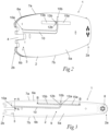
- a saw chain guide bar 1 according to a first embodiment of the present invention is illustrated in Figs 1-6 .
- the saw chain guide bar 1 is to be attached to a chainsaw cutting device of a tree harvester and is intended to co-operate with a saw chain of said cutting device.
- the saw chain guide bar 1 comprises an plate-shaped and elongated guide bar body 2, which has a rear end 2b and an opposite nose end 2a. At its rear end 2b, the guide bar body 2 has an attachment section 3 configured for attachment of the saw chain guide bar 1 to a chainsaw cutting device of a tree harvester by clamping.
- the attachment section 3 is in a conventional manner provided with a centre slot 4, which is configured to receive clamping bolts of the chainsaw cutting device.
- the guide bar body 2 has a first side face 5a extending between the rear end 2b and the nose end 2a and an opposite second side face 5b extending between the rear end 2b and the nose end 2a.
- a first saw chain guide track 6a extends along a first longitudinal edge 7a of the guide bar body 2 and a second saw chain guide track 6b extends along the opposite second longitudinal edge 7b of the guide bar body 2.
- a sprocket wheel 8 is in a conventional manner rotatably mounted to the guide bar body 2 at the nose end 2a thereof.
- a saw chain of the above-mentioned cutting device is to extend in a loop around the guide bar body 2 along the peripheral edge thereof while being in engagement with the sprocket wheel 8 and with the first and second saw chain guide tracks 6a, 6b.
- the saw chain is rotated and thereby driven along the peripheral edge of the guide bar body 2 by means of a driving motor of the cutting device.
- a liquid feed channel 10 extends along a part of the guide bar body 2 from the attachment section 3 towards the nose end 2a, the liquid feed channel 10 having an upstream end 10a located at the attachment section 3 and a downstream end 10b located at a distance from the attachment section 3.
- the liquid feed channel 10 has an inlet opening 11, through which the liquid feed channel is configured to receive pressurized liquid.
- the liquid is for instance an urea solution or any other desired tree stump treatment liquid and may be supplied to the liquid feed channel 10 from a liquid reservoir in the tree harvester by means of a pump.
- the inlet of the liquid feed channel 10 comprises one single inlet opening 11, but the liquid feed channel 10 may as an alternative be provided with an inlet that comprises two or more inlet openings.
- the liquid feed channel 10 has a first outlet 12a with a first spray outlet orifice 13a facing the nose end 2a of the guide bar body 2 and a second outlet 12b with a second spray outlet orifice 13b facing the rear end 2b of the guide bar body 2.
- the first and second outlets 12a, 12b are located opposite to each other on opposite sides of the liquid feed channel 10 and are both in fluid communication with the inlet opening 11 in order to receive liquid that has entered the liquid feed channel 10 through the inlet opening 11.
- the first spray outlet orifice 13a is configured to emit liquid from the liquid feed channel 10 as a liquid spray in a direction towards the nose end 2a of the guide bar body 2 and the second spray outlet orifice 13b is configured to emit liquid from the liquid feed channel 10 as a liquid spray in a direction towards the rear end 2b of the guide bar body 2.
- the first and second spray outlet orifices 13a, 13b are with advantage aligned with each other.
- the total cross-sectional area of the first and second spray outlet orifices 13a, 13b i.e. the sum of the cross-sectional area of the first spray outlet orifice 13a and the cross-sectional area of the second spray outlet orifice 13, is preferably smaller than the cross-sectional area of the inlet opening 11.
- the guide bar body 2 comprises a first spray guiding groove 15a, which is formed as an outwardly open elongated recess in the first side face 5a of the guide bar body 2 and which extends from the first outlet 12a of the liquid feed channel 10 along a part of the first side face 5a in a direction towards the nose end 2a of the guide bar body 2.
- the guide bar body 2 also comprises a second spray guiding groove 15b, which is formed as an outwardly open elongated recess in the first side face 5a of the guide bar body 2 and which extends from the second outlet 12b of the liquid feed channel 10 along a part of the first side face 5a in a direction towards the rear end 2b of the guide bar body 2.
- the first spray outlet orifice 13a opens into the first spray guiding groove 15a and the first spray guiding groove is configured to receive the liquid spray emitted from the first spray outlet orifice 13a and allow this liquid spray to propagate along the length of the first spray guiding groove 15a in a direction towards the nose end 2a of the guide bar body 2.
- the second spray outlet orifice 13b opens into the second spray guiding groove 15b and the second spray guiding groove is configured to receive the liquid spray emitted from the second spray outlet orifice 13b and allow this liquid spray to propagate along the length of the second spray guiding groove 15b in a direction towards the rear end 2b of the guide bar body 2.
- each spray guiding groove 15a, 15b extends in a straight line, or at least essentially straight line, along a part of the first side face 5a of the guide bar body 2, wherein the first and second spray guiding grooves 15a, 15b are aligned with each other.
- the first spray guiding groove 15a and/or the second spray guiding groove 15b may as an alternative be slightly curved as seen in the longitudinal direction of the guide bar body 2, as long as it allows the received liquid spray to propagate a certain distance in the longitudinal direction of the guide bar body 2.
- Each one of the first and second spray guiding grooves 15a, 15b preferably has a length of 80-200 mm and a width of 6-10 mm.
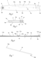
- each spray guiding groove 15a, 15b has an inclined bottom surface 16 (see Figs 1 and 6 ), which has such an inclination that the depth d of the spray guiding groove 15a, 15b is gradually decreasing as seen in a direction from a first end 17a of the spray guiding groove 15a, 15b facing the associated outlet 12a, 12b of the liquid feed channel 10 to an opposite second end 17b of the spray guiding groove 15a, 15b.
- each spray guiding groove 15a, 15b may as an alternative have one and the same depth all along its length or a depth that varies in any other suitable manner along the length thereof.
- the liquid feed channel 10 comprises:
- the liquid feed channel 10 is formed by an elongated tube 19 (see Fig 7 ), which is mounted in an elongated tube-accommodating groove 20 (see Fig 8 ) in the first side face 5a of the guide bar body 2.
- the tube 19 is with advantage mounted to the tube-accommodating groove 20 in the manner described in US 6 397 475 B1 , wherein the tube-accommodating groove 20 has undercut side walls 21, as illustrated in Fig 5 .
- the tube 19 is made of soft and deformable metal material, such as aluminium or cupper, and is originally made with a circular cross-sectional shape.
- the tube 19 is first bent in correspondence with the longitudinal shape of the tube-accommodating groove 20 and then positioned in this groove.
- the tube 19 After having been inserted into the tube-accommodating groove 20, the tube 19 is deformed by rolling or pressing until it fills the tube-accommodating groove 20 and conforms to the undercut side walls 21 thereof.
- the tube 19 is secured in the tube-accommodating groove 20 by having its cross-sectional shape deformed to conform to the undercut cross-sectional shape of the tube-accommodating groove.
- a channel-forming tube may of course also be secured to an associated tube-accommodating groove 20 in the guide bar body 2 in any other suitable manner.
- the liquid feed channel 10 may be formed as an integrated part of the guide bar body 2, for instance by being formed as an outwardly covered recess in the guide bar body 2.
- the bottom surface 22 of the tube-accommodating groove 20 has:
- Fig 9 illustrates the shape of the tube 19 when it has been deformed to conform to the shape of the tube-accommodating groove 20.
- the ends of the tube 19 may be sealed before the mounting thereof in the tube-accommodating groove 20.
- the inlet opening 11 and the spray outlet orifices 13a, 13b may be formed in the tube 19 before or after the mounting thereof in the tube-accommodating groove 20.
- the inlet opening 11 of the liquid feed channel 10 is facing the bottom surface 22 of the tube-accommodating groove 20, wherein the inlet opening 11 is aligned with and connected to a liquid supply hole 24 that extends through the guide bar body 2 between the second side face 5b and the tube-accommodating groove 20.
- the liquid enters the inlet opening 11 of the liquid feed channel 10 from the second side face 5b of the guide bar body 2 through the liquid supply hole 24.
- the inlet opening 11 of the liquid feed channel 10 may as an alternative be arranged on the outwardly facing side of the liquid feed channel 10, as illustrated in Fig 10 . In the latter case, the liquid enters the inlet opening 11 of the liquid feed channel 10 from the first side face 5a of the guide bar body 2.
- the first outlet 12a of the liquid feed channel 10 comprises one single outlet orifice 13a, but the first outlet 12a may as an alternative be provided with two or more outlet orifices 13a facing the nose end 2a of the guide bar body 2.
- the second outlet 12b of the liquid feed channel 10 comprises one single outlet orifice 13b, but the second outlet 12b may as an alternative be provided with two or more outlet orifices 13b facing the rear end 2b of the guide bar body 2.
- the saw chain guide bar 1 has a liquid feed channel 10 with two opposite outlets 12a, 12b and two associated spray guiding grooves 15a, 15b.
- the saw chain guide bar 1 may as an alternative have a liquid feed channel 10 with one single outlet comprising a spray outlet orifice facing the rear end 2b or the nose end 2a of the guide bar body 2 and one single spray guiding groove. If the spray outlet orifice of this single outlet faces the rear end 2b of the guide bar body 2, it is configured to emit liquid from the liquid feed channel 10 as a liquid spray in a direction towards the rear end 2b of the guide bar body 2, wherein the associated spray guiding groove extends from the outlet in a direction towards the rear end 2b of the guide bar body 2.
- the spray outlet orifice of said single outlet faces the nose end 2a of the guide bar body 2, it is configured to emit liquid from the liquid feed channel 10 as a liquid spray in a direction towards the nose end 2a of the guide bar body 2, wherein the associated spray guiding groove extends from the outlet in a direction towards the nose end 2a of the guide bar body 2.
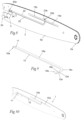
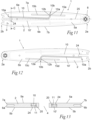
- the saw chain guide bar 1 comprises a first liquid feed channel 10 of the type described above for emitting liquid sprays on the first side face 5a of the guide bar body 2 and an additional second liquid feed channel 10' of the same type for emitting liquid sprays on the opposite second side face 5b of the guide bar body 2.
- first and second spray guiding grooves 15a, 15b are formed as outwardly open elongated recesses in the first side face 5a of the guide bar body 2 as described above with reference to Figs 1-6
- corresponding third and fourth spray guiding grooves 15c, 15d are formed as outwardly open elongated recesses in the second side face 5b of the guide bar body 2.
- the saw chain guide bar 1 illustrated in Figs 11-13 corresponds to the saw chain guide bar 1 described above with reference to Figs 1-6 .
- the saw chain guide bar 2 preferably has 180° rotational symmetry about a longitudinal centre axis 25 of the guide bar body 2.
- the first and second spray guiding grooves 15a, 15b are located on the first side face 5a of the guide bar body 2 adjacent to the first longitudinal edge 7a thereof, whereas the third and fourth spray guiding grooves 15c, 15d are located on the second side face 5b of the guide bar body 2 adjacent to the second longitudinal edge 7b thereof.
- the guide bar body 2 has the form of a solid body.
- the guide bar body 2 may as an alternative have the form of a laminated body formed by two or more separate plates.
Landscapes
- Life Sciences & Earth Sciences (AREA)
- Engineering & Computer Science (AREA)
- Mechanical Engineering (AREA)
- Wood Science & Technology (AREA)
- Forests & Forestry (AREA)
- Nozzles (AREA)
- Catching Or Destruction (AREA)
Claims (15)
- Führungsschiene für eine Sägekette, die Folgendes aufweist:- einen länglichen Führungsschienenkörper (2), der ein hinteres Ende (2b) und ein gegenüberliegendes vorderes Ende (2a) aufweist, wobei der Führungsschienenkörper (2) an seinem hinteren Ende (2b) einen Befestigungsabschnitt (3) aufweist, der derart ausgebildet ist, dass er an einer Kettensägen-Schneidvorrichtung einer Baumerntemaschine angebracht werden kann, und wobei der Führungsschienenkörper (2) eine erste Seitenfläche (5a), die sich zwischen dem hinteren Ende (2b) und dem vorderen Ende (2a) erstreckt, und eine gegenüberliegende zweite Seitenfläche (5b) aufweist, die sich zwischen dem hinteren Ende (2b) und dem vorderen Ende (2a) erstreckt und- einen Flüssigkeitszufuhrkanal (10), der sich entlang eines Teils des Führungsschienenkörpers (2) von dem Befestigungsabschnitt (3) in Richtung des vorderen Endes (2a) erstreckt, wobei der Flüssigkeitszufuhrkanal (10) ein stromaufwärts gelegenes Ende (10a), das sich am Befestigungsabschnitt (3) befindet, und ein stromabwärts gelegenes Ende (10b), das sich beabstandet vom Befestigungsabschnitt (3) befindet, aufweist, wobei der Flüssigkeitszufuhrkanal (10) an seinem stromaufwärts seitigen Ende (10a) eine Einlassöffnung (11) aufweist, durch die der Flüssigkeitszufuhrkanal (10) derart ausgebildet ist, dass er unter Druck stehende Flüssigkeit aufnimmt,
dadurch gekennzeichnet,- dass der Flüssigkeitszufuhrkanal (10) an seinem stromabwärts seitigen Ende (10b) einen ersten Auslass (12a) mit mindestens einer ersten Sprühauslassöffnung (13a) aufweist, die dem vorderen Ende (2a) oder dem hinteren Ende (2b) des Führungsschienenkörpers (2) zugewandt ist, wobei dieser erste Auslass (12a) in Fluidverbindung mit der Einlassöffnung (11) steht und derart ausgebildet ist, dass er von dort aufgenommene Flüssigkeit als Flüssigkeitsspray durch die mindestens eine erste Sprühauslassöffnung (13a) in Richtung des vorderen Endes (2a) des Führungsschienenkörpers (2) ausgibt, wenn die mindestens eine erste Sprühauslassöffnung (13a) dem vorderen Ende (2a) zugewandt ist, oder in Richtung des hinteren Endes (2b) des Führungsschienenkörpers (2) gerichtet ist, wenn die mindestens eine erste Sprühauslassöffnung (13a) dem hinteren Ende (2b) zugewandt ist; und- dass der Führungsschienenkörper (2) mit einer ersten Führungsnut (15a) für Sprühnebel versehen ist, die als eine nach außen offene längliche Aussparung in der ersten Seitenfläche (5a) des Führungsschienenkörpers (2) ausgebildet ist, wobei die mindestens eine erste Sprühauslassöffnung (13a) in die erste Führungsnut (15a) für Sprühnebel mündet und die erste Führungsnut (15a) für Sprühnebel sich von dem ersten Auslass (12a) des Flüssigkeitszufuhrkanals (10) in Richtung des vorderen Endes (2a) des Führungsschienenkörpers (2) erstreckt, wenn die mindestens eine erste Sprühauslassöffnung (13a) dem vorderen Ende (2a) zugewandt ist, oder in einer Richtung zum hinteren Ende (2b) des Führungsschienenkörpers (2) zeigt, wenn die mindestens eine erste Sprühauslassöffnung (13a) zum hinteren Ende (2b) zeigt. - Führungsschiene für eine Sägekette nach Anspruch 1, dadurch gekennzeichnet:- dass mindestens eine erste Sprühdüsenöffnung (13a) dem vorderen Ende (2a) des Führungsschienenkörpers (2) zugewandt ist;- dass der Flüssigkeitszufuhrkanal (10) an seinem stromabwärts seitigen Ende (10b) auch einen zweiten Auslass (12b) mit mindestens einer zweiten Sprühauslassöffnung (13b) aufweist, die dem hinteren Ende (2b) des Führungsschienenkörpers (2) zugewandt ist, wobei dieser zweite Auslass (12b) in Fluidverbindung mit der Einlassöffnung (11) steht und derart ausgebildet ist, dass er von dort aufgenommene Flüssigkeit als Flüssigkeitssprühnebel durch die mindestens eine zweite Sprühauslassöffnung (13b) in Richtung des hinteren Endes (2b) des Führungsschienenkörpers (2) ausgibt; und- dass der Führungsschienenkörper (2) mit einer zweiten Führungsnut (15b) für Sprühnebel versehen ist, die als eine nach außen offene längliche Aussparung in der ersten Seitenfläche (5a) des Führungsschienenkörpers (2) ausgebildet ist, wobei die mindestens eine zweite Sprühauslassöffnung (13b) in die zweite Führungsnut (15b) für Sprühnebel mündet und die zweite Führungsnut (15b) sich von dem zweiten Auslass (12b) des Flüssigkeitszufuhrkanals (10) in Richtung des hinteren Endes (2b) des Führungsschienenkörpers (2) erstreckt.
- Führungsschiene für eine Sägekette gemäß Anspruch 2, dadurch gekennzeichnet, dass der erste und der zweite Auslass (12a, 12b) einander gegenüberliegend auf gegenüberliegenden Seiten des Flüssigkeitszufuhrkanals (10) angeordnet sind.
- Führungsschiene für eine Sägekette nach Anspruch 2 oder 3, dadurch gekennzeichnet, dass der erste Auslass (12a) eine einzige erste Sprühauslassöffnung (13a) aufweist und dass der zweite Auslass (12b) eine einzige zweite Sprühauslassöffnung (13b) aufweist.
- Führungsschiene für eine Sägekette nach Anspruch 4, dadurch gekennzeichnet, dass die erste Sprühauslassöffnung (13a) und die zweite Sprühauslassöffnung (13b) zueinander fluchtend ausgerichtet sind.
- Führungsschiene für eine Sägekette gemäß mindestens einem der Ansprüche 2 bis 5, dadurch gekennzeichnet, dass jede der ersten und zweiten Führungsnuten (15a, 15b) für Sprühnebel eine Länge von 80 bis 200 mm und eine Breite von 6 bis 10 mm aufweist.
- Führungsschiene für eine Sägekette nach mindestens einem der Ansprüche 1 bis 6, dadurch gekennzeichnet, dass die Gesamtquerschnittsfläche aller Sprühauslassöffnungen (13a, 13b) des Flüssigkeitszufuhrkanals (10) kleiner ist als die Querschnittsfläche der Einlassöffnung (11) des Flüssigkeitszufuhrkanals (10).
- Führungsschiene für eine Sägekette nach mindestens einem der Ansprüche 1 bis 7, dadurch gekennzeichnet, dass sich jede Führungsnut (15a, 15b) für Sprühnebel in einer geraden Linie oder zumindest im Wesentlichen in einer geraden Linie entlang eines Teils der ersten Seitenfläche (5a) des Führungsschienenkörpers (2) erstreckt.
- Führungsschiene für eine Sägekette nach Anspruch 8 in Kombination mit mindestens einem der Ansprüche 2 bis 6, dadurch gekennzeichnet, dass die erste und die zweite Führungsnut (15a, 15b) für Sprühnebel fluchtend zueinander ausgerichtet sind.
- Führungsschiene für eine Sägekette nach mindestens einem der Ansprüche 1 bis 9, dadurch gekennzeichnet, dass jede Führungsnut (15a, 15b) für Sprühnebel eine schräge Bodenfläche (16) aufweist, wobei die Schräge derart ausgebildet ist, dass die Tiefe (d) der Führungsnut (15a, 15b) für Sprühnebel kontinuierlich abnimmt, in einer Richtung von einem ersten Ende (17a) der Führungsnut (15a, 15b) für Sprühnebel, das dem zugehörigen Auslass (12a, 12b) des Flüssigkeitszufuhrkanals (10) zugewandt ist, zu einem gegenüberliegenden zweiten Ende (17b) der Führungsnut (15a, 15b) für Sprühnebel gesehen.
- Führungsschiene für eine Sägekette nach mindestens einem der Ansprüche 1 bis 10, dadurch gekennzeichnet, dass der Flüssigkeitszufuhrkanal (10) folgendes aufweist:- ein gerades oder zumindest im Wesentlichen gerades erstes Teil (18a), das sich vom Befestigungsabschnitt (3) des Führungsschienenkörpers (2) zu einem Mittelabschnitt (9) des Führungsschienenkörpers (2) erstreckt, der sich in Längsrichtung des Führungsschienenkörpers (2) in der Mitte desselben befindet, wobei dieser erste Teil (18a) keine Sprühauslassöffnungen aufweist;- ein gerades oder zumindest im Wesentlichen gerades zweites Teil (18b), das sich in einem Winkel von 80 bis 100°, vorzugsweise 90°, zum ersten Teil (18a) erstreckt, wobei die Sprühauslassöffnung oder -öffnungen (13a, 13b) in diesem zweiten Teil (18b) angeordnet sind; und- ein gekrümmtes drittes Teil (18c), das eine Verbindung zwischen dem ersten Teil (18a) und dem zweiten Teil (18b) ausbildet, wobei dieses dritte Teil (18c) frei von Sprühauslassöffnungen ist.
- Führungsschiene für eine Sägekette nach mindestens einem der Ansprüche 1 bis 11, dadurch gekennzeichnet, dass der Flüssigkeitszufuhrkanal (10) durch ein längliches Rohr (19) ausgebildet ist, das in einer Aufnahmenut (20) für längliche Rohre in der ersten Seitenfläche (5a) des Führungsschienenkörpers (2) montiert ist.
- Führungsschiene für eine Sägekette gemäß Anspruch 12, dadurch gekennzeichnet, dass eine Bodenfläche (22) der Aufnahmenut (20) für das Rohr Folgendes aufweist:- einen geneigten ersten Rampenabschnitt (23a) an einem ersten Ende (20a) der Aufnahmenut (20) für das Rohr, wobei dieser erste Rampenabschnitt (23a) eine derartige Neigung aufweist, dass die Tiefe der Aufnahmenut (20) für das Rohr kontinuierlich erhöht wird, in eine Richtung von einem ersten Ende des ersten Rampenabschnitts (23a), das dem ersten Ende (20a) der Aufnahmenut (20) für das Rohr zugewandt ist, zu einem gegenüberliegenden zweiten Ende des ersten Rampenabschnitts (23a) gesehen; und- einen geneigten zweiten Rampenabschnitt (23b) an einem zweiten Ende (20b) der Aufnahmenut (20) für das Rohr, wobei dieser zweite Rampenabschnitt (23b) eine derartige Neigung aufweist, dass die Tiefe der Aufnahmenut (20) für das Rohr kontinuierlich erhöht wird, in einer Richtung von einem ersten Ende des zweiten Rampenabschnitts (23b), das dem zweiten Ende (20b) der Aufnahmenut (20) für das Rohr zugewandt ist, zu einem gegenüberliegenden zweiten Ende des zweiten Rampenabschnitts (23b) gesehen.
- Führungsschiene für eine Sägekette nach mindestens einem der Ansprüche 1 bis 13, dadurch gekennzeichnet:- dass die Führungsschiene (1) der Sägekette einen zusätzlichen Flüssigkeitszufuhrkanal (10') aufweist, der sich entlang eines Teils des Führungsschienenkörpers (2) vom Befestigungsabschnitt (3) zum vorderen Ende (2a) erstreckt, wobei der zusätzliche Flüssigkeitszufuhrkanal (10') ein stromaufwärts gelegenes Ende (10a) am Befestigungsabschnitt (3) und ein stromabwärts gelegenes Ende (10b) beabstandet vom Befestigungsabschnitt (3) aufweist, wobei der zusätzliche Flüssigkeitszufuhrkanal (10') an seinem stromaufwärts seitigen Ende (10a) eine Einlassöffnung (11) aufweist, durch die der zusätzliche Flüssigkeitszufuhrkanal (10') derart ausgebildet ist, dass er unter Druck stehende Flüssigkeit aufnimmt;- dass der zusätzliche Flüssigkeitszufuhrkanal (10') an seinem stromabwärts seitigen Ende (10b) einen ersten Auslass (12a) mit mindestens einer ersten Sprühauslassöffnung (13a), die dem vorderen Ende (2a) des Führungsschienenkörpers (2) zugewandt ist, und einen zweiten Auslass (12b) mit mindestens einer zweiten Sprühauslassöffnung (13b), die dem hinteren Ende (2b) des Führungsschienenkörpers (2) zugewandt ist, aufweist, wobei der erste Auslass (12a) des zusätzlichen Flüssigkeitszufuhrkanals (10') in Fluidverbindung mit der Einlassöffnung (11) des zusätzlichen Flüssigkeitszufuhrkanals (10') steht und derart ausgebildet ist, dass er von dort aufgenommene Flüssigkeit als Flüssigkeitssprühnebel durch die mindestens eine erste Sprühauslassöffnung (13a) in Richtung des vorderen Endes (2a) des Führungsschienenkörpers (2) ausgibt, und wobei der zweite Auslass (12b) des zusätzlichen Flüssigkeitszufuhrkanals (10') in Fluidverbindung mit der Einlassöffnung (11) des zusätzlichen Flüssigkeitszufuhrkanals (10') steht und derart ausgebildet ist, dass er die von dort aufgenommene Flüssigkeit als Flüssigkeitssprühnebel durch die mindestens eine zweite Sprühauslassöffnung (13b) in Richtung des hinteren Endes (2b) des Führungsschienenkörpers (2) ausgibt;- dass der Führungsschienenkörper (2) mit einer dritten Führungsnut (15c) für Sprühnebel versehen ist, die als eine nach außen offene längliche Aussparung in der zweiten Seitenfläche (5b) des Führungsschienenkörpers (2) ausgebildet ist, wobei die mindestens eine erste Sprühauslassöffnung (13a) des zusätzlichen Flüssigkeitszufuhrkanals (10') in die dritte Führungsnut (15c) für Sprühnebel mündet und die dritte Führungsnut (15c) für Sprühnebel sich vom ersten Auslass (12a) des zusätzlichen Flüssigkeitszufuhrkanals (10') in Richtung des vorderen Endes (2a) des Führungsschienenkörpers (2) erstreckt; und- dass der Führungsschienenkörper (2) mit einer vierten Führungsnut (15d) für Sprühnebel versehen ist, die als eine nach außen offene längliche Aussparung in der zweiten Seitenfläche (5b) des Führungsschienenkörpers (2) ausgebildet ist, wobei die mindestens eine zweite Sprühauslassöffnung (13b) des zusätzlichen Flüssigkeitszufuhrkanals (10') in die vierte Führungsnut (15d) für Sprühnebel mündet und die vierte Führungsnut (15d) für Sprühnebel sich vom zweiten Auslass (12b) des zusätzlichen Flüssigkeitszufuhrkanals (10') in Richtung des hinteren Endes (2b) des Führungsschienenkörpers (2) erstreckt.
- Führungsschiene für eine Sägekette nach einem der Ansprüche 1 bis 14, dadurch gekennzeichnet, dass die Führungsschiene (1) für eine Sägekette um 180° rotationssymmetrisch um eine längs verlaufende Mittelachse (25) des Führungsschienenkörpers (2) ausgebildet ist.
Priority Applications (6)
| Application Number | Priority Date | Filing Date | Title |
|---|---|---|---|
| PL22213659.0T PL4385692T3 (pl) | 2022-12-15 | 2022-12-15 | Prowadnica łańcucha piły |
| HUE22213659A HUE072365T2 (hu) | 2022-12-15 | 2022-12-15 | Fûrészlánc vezetõ |
| HRP20250832TT HRP20250832T1 (hr) | 2022-12-15 | 2022-12-15 | Vodilica lanca motorne pile |
| EP22213659.0A EP4385692B1 (de) | 2022-12-15 | 2022-12-15 | Führungsschiene für sägekette |
| ES22213659T ES3040642T3 (en) | 2022-12-15 | 2022-12-15 | Saw chain guide bar |
| PCT/EP2023/079274 WO2024125864A1 (en) | 2022-12-15 | 2023-10-20 | Saw chain guide bar |
Applications Claiming Priority (1)
| Application Number | Priority Date | Filing Date | Title |
|---|---|---|---|
| EP22213659.0A EP4385692B1 (de) | 2022-12-15 | 2022-12-15 | Führungsschiene für sägekette |
Publications (3)
| Publication Number | Publication Date |
|---|---|
| EP4385692A1 EP4385692A1 (de) | 2024-06-19 |
| EP4385692C0 EP4385692C0 (de) | 2025-06-18 |
| EP4385692B1 true EP4385692B1 (de) | 2025-06-18 |
Family
ID=84537000
Family Applications (1)
| Application Number | Title | Priority Date | Filing Date |
|---|---|---|---|
| EP22213659.0A Active EP4385692B1 (de) | 2022-12-15 | 2022-12-15 | Führungsschiene für sägekette |
Country Status (6)
| Country | Link |
|---|---|
| EP (1) | EP4385692B1 (de) |
| ES (1) | ES3040642T3 (de) |
| HR (1) | HRP20250832T1 (de) |
| HU (1) | HUE072365T2 (de) |
| PL (1) | PL4385692T3 (de) |
| WO (1) | WO2024125864A1 (de) |
Family Cites Families (3)
| Publication number | Priority date | Publication date | Assignee | Title |
|---|---|---|---|---|
| SE517597E (sv) | 1999-10-28 | 2007-10-30 | Blount Inc | Kedjesågstyrgejd med vätskekanaler |
| SE0001773L (sv) | 2000-05-15 | 2001-07-16 | Rolf Goesta Gustafsson | Sågsvärdsarrangemang för svampbekämpning |
| US6397452B1 (en) | 2001-05-30 | 2002-06-04 | Blount, Inc. | Guide bar including stump treatment |
-
2022
- 2022-12-15 PL PL22213659.0T patent/PL4385692T3/pl unknown
- 2022-12-15 ES ES22213659T patent/ES3040642T3/es active Active
- 2022-12-15 HU HUE22213659A patent/HUE072365T2/hu unknown
- 2022-12-15 HR HRP20250832TT patent/HRP20250832T1/hr unknown
- 2022-12-15 EP EP22213659.0A patent/EP4385692B1/de active Active
-
2023
- 2023-10-20 WO PCT/EP2023/079274 patent/WO2024125864A1/en not_active Ceased
Also Published As
| Publication number | Publication date |
|---|---|
| HRP20250832T1 (hr) | 2025-09-12 |
| EP4385692C0 (de) | 2025-06-18 |
| PL4385692T3 (pl) | 2025-10-20 |
| WO2024125864A1 (en) | 2024-06-20 |
| ES3040642T3 (en) | 2025-11-03 |
| HUE072365T2 (hu) | 2025-11-28 |
| EP4385692A1 (de) | 2024-06-19 |
Similar Documents
| Publication | Publication Date | Title |
|---|---|---|
| US5050303A (en) | Chain saw bar fluid passage system | |
| US5143131A (en) | Selectable spray pattern chain saw bar system | |
| US5426854A (en) | Chain saw guide bar with liquid spray device | |
| WO2003005799A3 (en) | A stabilised agricultural apparatus | |
| US5778537A (en) | Chain saw guide bar with liquid spray device | |
| US10292342B2 (en) | Harvester head assembly | |
| EP4385692B1 (de) | Führungsschiene für sägekette | |
| US6619171B2 (en) | Guide bar for tree harvesting including stump treatment | |
| JP4014621B2 (ja) | 植物の刈り取り及び処理を行う方法 | |
| CA1172138A (en) | Chain saw with wedge-shaped, chain-protecting chain support | |
| JP3886989B2 (ja) | 茶園用薬剤散布機 | |
| US6073389A (en) | Stump dabber | |
| AU676864B2 (en) | Colour-marking assembly in the cutting flange of a timber harvester | |
| WO1991014356A1 (en) | Billet planter | |
| WO1995027599A1 (en) | Method and device for treating a tree stump | |
| RU2201294C1 (ru) | Способ создания воздушно-жидкостного потока | |
| EP1050208B1 (de) | Vorrichtung zum Behandeln von Baumstümpfen | |
| KR200322935Y1 (ko) | 식물재배용 내장형 점적기 | |
| JP3968312B2 (ja) | 薬液撒布装置。 | |
| US20220168759A1 (en) | Nozzle and sprinkler for center pivot end | |
| NZ575196A (en) | Combined cutter and sprayer for the control of woody growths or weeds | |
| JPH0477628B2 (de) | ||
| JPH0321365A (ja) | 薬液散布装置 | |
| GB2429894A (en) | Apparatus for applying weed killing liquid to weeds |
Legal Events
| Date | Code | Title | Description |
|---|---|---|---|
| REG | Reference to a national code |
Ref country code: HR Ref legal event code: TUEP Ref document number: P20250832T Country of ref document: HR |
|
| PUAI | Public reference made under article 153(3) epc to a published international application that has entered the european phase |
Free format text: ORIGINAL CODE: 0009012 |
|
| STAA | Information on the status of an ep patent application or granted ep patent |
Free format text: STATUS: THE APPLICATION HAS BEEN PUBLISHED |
|
| AK | Designated contracting states |
Kind code of ref document: A1 Designated state(s): AL AT BE BG CH CY CZ DE DK EE ES FI FR GB GR HR HU IE IS IT LI LT LU LV MC ME MK MT NL NO PL PT RO RS SE SI SK SM TR |
|
| STAA | Information on the status of an ep patent application or granted ep patent |
Free format text: STATUS: REQUEST FOR EXAMINATION WAS MADE |
|
| 17P | Request for examination filed |
Effective date: 20240913 |
|
| RBV | Designated contracting states (corrected) |
Designated state(s): AL AT BE BG CH CY CZ DE DK EE ES FI FR GB GR HR HU IE IS IT LI LT LU LV MC ME MK MT NL NO PL PT RO RS SE SI SK SM TR |
|
| GRAP | Despatch of communication of intention to grant a patent |
Free format text: ORIGINAL CODE: EPIDOSNIGR1 |
|
| STAA | Information on the status of an ep patent application or granted ep patent |
Free format text: STATUS: GRANT OF PATENT IS INTENDED |
|
| INTG | Intention to grant announced |
Effective date: 20250220 |
|
| GRAS | Grant fee paid |
Free format text: ORIGINAL CODE: EPIDOSNIGR3 |
|
| GRAA | (expected) grant |
Free format text: ORIGINAL CODE: 0009210 |
|
| STAA | Information on the status of an ep patent application or granted ep patent |
Free format text: STATUS: THE PATENT HAS BEEN GRANTED |
|
| AK | Designated contracting states |
Kind code of ref document: B1 Designated state(s): AL AT BE BG CH CY CZ DE DK EE ES FI FR GB GR HR HU IE IS IT LI LT LU LV MC ME MK MT NL NO PL PT RO RS SE SI SK SM TR |
|
| RAP3 | Party data changed (applicant data changed or rights of an application transferred) |
Owner name: IGGESUND FOREST AB |
|
| REG | Reference to a national code |
Ref country code: GB Ref legal event code: FG4D |
|
| REG | Reference to a national code |
Ref country code: CH Ref legal event code: EP |
|
| REG | Reference to a national code |
Ref country code: CH Ref legal event code: EP |
|
| REG | Reference to a national code |
Ref country code: IE Ref legal event code: FG4D |
|
| U01 | Request for unitary effect filed |
Effective date: 20250624 |
|
| U07 | Unitary effect registered |
Designated state(s): AT BE BG DE DK EE FI FR IT LT LU LV MT NL PT RO SE SI Effective date: 20250701 |
|
| REG | Reference to a national code |
Ref country code: HR Ref legal event code: T1PR Ref document number: P20250832 Country of ref document: HR |
|
| PG25 | Lapsed in a contracting state [announced via postgrant information from national office to epo] |
Ref country code: GR Free format text: LAPSE BECAUSE OF FAILURE TO SUBMIT A TRANSLATION OF THE DESCRIPTION OR TO PAY THE FEE WITHIN THE PRESCRIBED TIME-LIMIT Effective date: 20250919 |
|
| REG | Reference to a national code |
Ref country code: SK Ref legal event code: T3 Ref document number: E 46939 Country of ref document: SK |
|
| PG25 | Lapsed in a contracting state [announced via postgrant information from national office to epo] |
Ref country code: RS Free format text: LAPSE BECAUSE OF FAILURE TO SUBMIT A TRANSLATION OF THE DESCRIPTION OR TO PAY THE FEE WITHIN THE PRESCRIBED TIME-LIMIT Effective date: 20250918 |
|
| REG | Reference to a national code |
Ref country code: ES Ref legal event code: FG2A Ref document number: 3040642 Country of ref document: ES Kind code of ref document: T3 Effective date: 20251103 |
|
| REG | Reference to a national code |
Ref country code: HU Ref legal event code: AG4A Ref document number: E072365 Country of ref document: HU |
|
| REG | Reference to a national code |
Ref country code: HR Ref legal event code: ODRP Ref document number: P20250832 Country of ref document: HR Payment date: 20251119 Year of fee payment: 4 |
|
| REG | Reference to a national code |
Ref country code: CH Ref legal event code: U11 Free format text: ST27 STATUS EVENT CODE: U-0-0-U10-U11 (AS PROVIDED BY THE NATIONAL OFFICE) Effective date: 20260101 |
|
| PG25 | Lapsed in a contracting state [announced via postgrant information from national office to epo] |
Ref country code: IS Free format text: LAPSE BECAUSE OF FAILURE TO SUBMIT A TRANSLATION OF THE DESCRIPTION OR TO PAY THE FEE WITHIN THE PRESCRIBED TIME-LIMIT Effective date: 20251018 |
|
| PGFP | Annual fee paid to national office [announced via postgrant information from national office to epo] |
Ref country code: NO Payment date: 20251219 Year of fee payment: 4 |
|
| PG25 | Lapsed in a contracting state [announced via postgrant information from national office to epo] |
Ref country code: SM Free format text: LAPSE BECAUSE OF FAILURE TO SUBMIT A TRANSLATION OF THE DESCRIPTION OR TO PAY THE FEE WITHIN THE PRESCRIBED TIME-LIMIT Effective date: 20250618 |
|
| PGFP | Annual fee paid to national office [announced via postgrant information from national office to epo] |
Ref country code: HR Payment date: 20251119 Year of fee payment: 4 Ref country code: HU Payment date: 20251202 Year of fee payment: 4 |
|
| PGFP | Annual fee paid to national office [announced via postgrant information from national office to epo] |
Ref country code: TR Payment date: 20251128 Year of fee payment: 4 |
|
| PGFP | Annual fee paid to national office [announced via postgrant information from national office to epo] |
Ref country code: IE Payment date: 20251215 Year of fee payment: 4 Ref country code: CZ Payment date: 20251120 Year of fee payment: 4 |
|
| U20 | Renewal fee for the european patent with unitary effect paid |
Year of fee payment: 4 Effective date: 20251216 |
|
| PGFP | Annual fee paid to national office [announced via postgrant information from national office to epo] |
Ref country code: PL Payment date: 20251118 Year of fee payment: 4 |
|
| PGFP | Annual fee paid to national office [announced via postgrant information from national office to epo] |
Ref country code: SK Payment date: 20251121 Year of fee payment: 4 |