EP4385650A1 - Inner burr removing knife rest structure - Google Patents
Inner burr removing knife rest structure Download PDFInfo
- Publication number
- EP4385650A1 EP4385650A1 EP22894552.3A EP22894552A EP4385650A1 EP 4385650 A1 EP4385650 A1 EP 4385650A1 EP 22894552 A EP22894552 A EP 22894552A EP 4385650 A1 EP4385650 A1 EP 4385650A1
- Authority
- EP
- European Patent Office
- Prior art keywords
- tool holder
- rod
- base
- tool
- roller
- Prior art date
- Legal status (The legal status is an assumption and is not a legal conclusion. Google has not performed a legal analysis and makes no representation as to the accuracy of the status listed.)
- Pending
Links
Images



Classifications
-
- B—PERFORMING OPERATIONS; TRANSPORTING
- B23—MACHINE TOOLS; METAL-WORKING NOT OTHERWISE PROVIDED FOR
- B23D—PLANING; SLOTTING; SHEARING; BROACHING; SAWING; FILING; SCRAPING; LIKE OPERATIONS FOR WORKING METAL BY REMOVING MATERIAL, NOT OTHERWISE PROVIDED FOR
- B23D79/00—Methods, machines, or devices not covered elsewhere, for working metal by removal of material
- B23D79/02—Machines or devices for scraping
- B23D79/021—Machines or devices for scraping for removing welding, brazing or soldering burrs, e.g. flash, on pipes or rods
- B23D79/023—Machines or devices for scraping for removing welding, brazing or soldering burrs, e.g. flash, on pipes or rods internally
-
- B—PERFORMING OPERATIONS; TRANSPORTING
- B23—MACHINE TOOLS; METAL-WORKING NOT OTHERWISE PROVIDED FOR
- B23Q—DETAILS, COMPONENTS, OR ACCESSORIES FOR MACHINE TOOLS, e.g. ARRANGEMENTS FOR COPYING OR CONTROLLING; MACHINE TOOLS IN GENERAL CHARACTERISED BY THE CONSTRUCTION OF PARTICULAR DETAILS OR COMPONENTS; COMBINATIONS OR ASSOCIATIONS OF METAL-WORKING MACHINES, NOT DIRECTED TO A PARTICULAR RESULT
- B23Q11/00—Accessories fitted to machine tools for keeping tools or parts of the machine in good working condition or for cooling work; Safety devices specially combined with or arranged in, or specially adapted for use in connection with, machine tools
- B23Q11/0042—Devices for removing chips
- B23Q11/005—Devices for removing chips by blowing
Definitions
- the present disclosure relates to the technical field of metal machining devices, and more specifically, to an inner burr removal tool holder structure.
- a longitudinally welded pipe is a pipe made by rolling a long strip of metal strip of a certain specification into a round tube or another shape by using a high-frequency welding set, and longitudinally welding the pipe, and a weld seam is axially parallel to a metal pipe.
- a shape of the longitudinally welded pipe may be round, square, or special-shaped, depending on sizing and rolling after welding.
- a production process of the longitudinally welded pipe is simple, production efficiency is high, costs are low, and a development is fast.
- An existing tool holder structure for removing the inner burrs is provided, and in the welding process of the longitudinally welded pipe, the weld seam is cut, by extending the tool holder structure inside of the longitudinally welded pipe, to achieve a purpose of removing the inner burrs.
- the tool holder structure usually moves in a straight line along the weld seam, and it is easy to cause burr accumulation on the tool holder structure, and accuracy and stability control of burr removal in the longitudinally welded pipe is poor.
- the present disclosure provides an inner burr removal tool holder structure.
- the present disclosure provides an inner burr removal tool holder structure, including a tool holder body.
- the tool holder body includes a tool base and a connecting rod assembly.
- the connecting rod assembly is connected to the tool base.
- a scraper for removing inner burrs and a nozzle for spraying liquid is arranged on the tool base. The scraper protrudes from an outer surface of the tool base, and a liquid outlet of the nozzle faces the scraper.
- a stepped hole is provided in the tool base, and at least one gasket is arranged on a stepped surface of the stepped hole.
- the gasket is a partial hollow-out structure, and the scraper is an annular structure. The scraper is embedded in the stepped hole and is abutted against the gasket, and the scraper is partially exposed in the stepped hole.
- the connecting rod assembly includes a first water channel.
- the first water channel extends along the connecting rod assembly, and the first water channel is communicated with the nozzle.
- a first roller protruding from the outer surface of the tool base is arranged on the tool base, and an annular relief slot is provided in an outer wall of the first roller along a circumferential direction of the first roller.
- first rollers there are multiple first rollers.
- a first accommodation slot accommodating the first roller is provided in the outer surface of the tool base, and two sides of the first roller are rotatably connected to an inner wall of the first accommodation slot.
- the tool holder body further includes a roller base.
- the tool base and the roller base are respectively located at two sides of an end of the connecting rod assembly, and a second roller protruding from an outer surface of the roller base is arranged on the roller base.
- a second accommodation slot accommodating the second roller is provided in the outer surface of the roller base, and two sides of the second roller are rotatably connected to an inner wall of the second accommodation slot.
- the connecting rod assembly includes a first tool holder rod, a second tool holder rod, a third tool holder rod, and a fourth tool holder rod.
- the first tool holder rod, the second tool holder rod, the third tool holder rod, and the fourth tool holder rod are connected end-to-end in sequence.
- the tool base is arranged at an end of the fourth tool holder rod.
- the first tool holder rod, the second tool holder rod, the third tool holder rod, and the fourth tool holder rod extend along a straight line.
- the first tool holder rod, the second tool holder rod, the third tool holder rod, and the fourth tool holder rod are matched in a concave-convex structure, and are fastened and connected by using screws.
- a magnetic rod is arranged on the second tool holder rod, and the magnetic rod extends along an outer wall of the second tool holder rod.
- the connecting rod assembly further includes a second water channel, and the second water channel flows through the magnetic rod.
- the second water channel includes a water inlet pipe, a through channel, a cooling channel, and a water outlet pipe.
- a protective sleeve is arranged outside the magnetic rod, an inner wall of the protective sleeve and an outer wall of the magnetic rod constitute the cooling channel.
- the water inlet pipe and the water outlet pipe are arranged on the first tool holder rod.
- the through channel is arranged inside the second tool holder rod. The water inlet pipe is communicated with the through channel, the through channel is communicated with the cooling channel, and the cooling channel is communicated with the water outlet pipe.
- the inner burr removal tool holder structure further includes a tool rod mounting base and a supporting base.
- An end of the connecting rod assembly away from the tool base is fixed on the tool rod mounting base.
- a height-adjusting structure for adjusting a height is provided on the tool rod mounting base.
- the supporting base is configured to support a longitudinally welded pipe to allow for insertion of the tool base.
- the height-adjusting structure includes a sliding block, an adjusting base, a threaded rod, and a rotating handle.
- the sliding block is fixed at the end of the connecting rod assembly away from the tool base.
- the sliding block is arranged on the adjusting base in a vertically slidable manner.
- the threaded rod is rotatably connected to the adjusting base, and the threaded rod passes through the sliding block and is threadedly fitted with the sliding block.
- the rotating handle is connected to the threaded rod. The rotating handle can be rotated to implement height adjustments of the connecting rod assembly and the tool base via the threaded fit of the threaded rod and the sliding block.
- a plurality of upper supporting wheels and a plurality of lower supporting wheels are arranged on the supporting base.
- the upper supporting wheels and the lower supporting wheels are spaced apart from each other in the vertical direction to support the longitudinally welded pipe.
- the nozzle for spraying liquid is arranged on one side of the scraper, and when the nozzle can perform an inner burr removal operation of a longitudinally welded pipe by using the scraper, cooling water is sprayed at a position of the scraper, so that burrs accumulated on the scraper are dispersed, accumulation of burrs on the scraper is avoided, burrs that are sprayed down flows out of the longitudinally welded pipe with the cooling water, and the cooling water also cools the scraper. This avoids performance deterioration of caused by overheating of the scraper, and effectively improves a service life of the scraper.
- an embodiment of the present disclosure provides an inner burr removal tool holder structure, including a tool holder body.
- the tool holder body includes a tool base 2 and a connecting rod assembly 1.
- the connecting rod assembly 1 is connected to the tool base 2.
- a scraper 24 for removing inner burrs and a nozzle 23 for spraying liquid is arranged on the tool base 2.
- the scraper 24 protrudes from an outer surface of the tool base 2, and a liquid outlet of the nozzle 23 faces the scraper 24.
- the nozzle 23 for spraying liquid is arranged on one side of the scraper 24, and when the nozzle 23 can perform an inner burr removal operation of a longitudinally welded pipe by using the scraper 24, cooling water is sprayed at a position of the scraper 24, so that burrs accumulated on the scraper 24 are dispersed, accumulation of burrs on the scraper 24 is avoided, burrs that are sprayed down flows out of the longitudinally welded pipe with the cooling water, and the cooling water also cools the scraper 24. This avoids performance deterioration caused by overheating of the scraper 24, and effectively improves a service life of the scraper 24.
- a stepped hole 25 is provided in the tool base 2, and at least one gasket 26 is arranged on a stepped surface of the stepped hole 25.
- the gasket 26 is a partial hollow-out structure, and the scraper 24 is an annular structure.
- the scraper 24 is embedded in the stepped hole 25 and is abutted against the gasket 26, and the scraper 24 is partially exposed in the stepped hole 25.
- the gasket 26 is used for adjusting a height of the scraper 24 protruding from the stepped hole 25. Specifically, a thickness of the gasket 26 or a quantity of stacks can be adjusted to adjust a distance between the scraper 24 and the stepped surface of the stepped hole 25, and the protruding height of the scraper 24 can be adjusted, so that the inner burr removal tool holder structure adjusts an inner burr scraping height of a longitudinally welded pipe to improve adjustment accuracy.
- the scraper 24 is an annular structure, burrs scraped off by the scraper 24 may fall from the bottom of the stepped hole 25 through a middle hole of the scraper 24, to reduce a risk of burr accumulation.
- the gasket 26 is arranged as a partial hollow-out structure, so that blockage of the stepped hole 25 by burrs due to the use of the gasket 26 can be avoided.
- the gasket 26 may be selected from a grid structure or another opening structure.
- the connecting rod assembly 1 includes a first water channel 4, the first water channel 4 extends along the connecting rod assembly 1, and the first water channel 4 is communicated with the nozzle 23.
- a first roller 21 protruding from the outer surface of the tool base 2 is arranged on the tool base 2, and an annular relief slot 211 is provided in an outer wall of the first roller 21 along a circumferential direction of the first roller 21.
- the first roller 21 is configured to be in contact with an inner wall of the longitudinally welded pipe to reduce frictional force of the tool holder body moving inside the longitudinally welded pipe. Because the first roller 21 is used as a support of the tool base 2, in a process of scraping off the inner burrs by using the scraper 24, the tool base 2 moves relative to the longitudinally welded pipe, the first roller 21 produces compressive force to a straight weld seam, and the straight weld seam that just be welded is fragile, so that the straight weld seam is easily crushed by the first roller 21.
- the annular relief slot 211 is provided in the circumferential direction of the first roller 21, and in a process of rolling the first roller 21, the annular relief slot 211 is used for passage of the straight weld seam of the longitudinally welded pipe, to avoid an impact of the first roller 21 on the straight weld seam of the longitudinally welded pipe.
- a first accommodation slot 22 accommodating the first roller 21 is provided in the outer surface of the tool base 2, and two sides of the first roller 21 are rotatably connected to an inner wall of the first accommodation slot 22, to prevent the first roller 21 from excessively protruding from the outer surface of the tool base 2.
- the tool holder body further includes a roller base 3.
- the tool base 2 and the roller base 3 are respectively located at two sides of an end of the connecting rod assembly 1, and a second roller 31 protruding from an outer surface of the roller base 3 is arranged on the roller base 3.
- a function of the second roller 31 is similar to that of the first roller 21, and the second roller 31 and the first roller 21 are both configured to be in contact with the inner wall of the longitudinally welded pipe to reduce the frictional force of the tool holder body moving inside the longitudinally welded pipe.
- a second accommodation slot 32 accommodating the second roller 31 is provided in the outer surface of the roller base 3, and two sides of the second roller 31 are rotatably connected to an inner wall of the second accommodation slot 32, to prevent the second roller 31 from excessively protruding from the outer surface of the roller base 3.
- the connecting rod assembly 1 includes a first tool holder rod 11, a second tool holder rod 12, a third tool holder rod 13, and a fourth tool holder rod 14.
- the first tool holder rod 11, the second tool holder rod 12, the third tool holder rod 13, and the fourth tool holder rod 14 are connected end-to-end in sequence.
- the tool base 2 is arranged at an end of the fourth tool holder rod 14.
- the tool base 2 and the roller base 3 are respectively located at two sides of the end of the fourth tool holder rod 14.
- the first tool holder rod 11, the second tool holder rod 12, the third tool holder rod 13, and the fourth tool holder rod 14 extend along a straight line.
- the first tool holder rod 11, the second tool holder rod 12, the third tool holder rod 13, and the fourth tool holder rod 14 are matched in a concave-convex structure, and are fastened and connected by using screws.
- a magnetic rod 6 is arranged on the second tool holder rod 12, and the magnetic rod 6 extends along an outer wall of the second tool holder rod 12.
- the magnetic rod 6 is used as an impedor, and when a welding operation of the longitudinally welded pipe is performed, the magnetic rod 6 may be moved to a corresponding position of an induction coil. The operation is used to cancel an impact of part of high-frequency induced magnetic fields generated by the induction coil on the second tool holder rod 12, to avoid overheating and melting of the second tool holder rod 12.
- the connecting rod assembly 1 further includes a second water channel 5, and the second water channel 5 flows through the magnetic rod 6.
- a temperature of a welding position is high, if a problem of overheating occurs on the magnetic rod 6, the magnetic rod 6 is damaged.
- the magnetic rod 6 is cooled down by setting the second water channel 5, so that a problem that a temperature of the magnetic rod 6 is excessively high is avoided.
- the second water channel 5 includes a water inlet pipe 51, a through channel 52, a cooling channel 53, and a water outlet pipe 54.
- a protective sleeve 61 is arranged outside the magnetic rod 6, an inner wall of the protective sleeve 61 and an outer wall of the magnetic rod 6 constitute the cooling channel 53.
- the protective sleeve 61 has a good protective effect on the magnetic rod 6, so that an abrasion of the magnetic rod 6 in a moving process of the longitudinally welded pipe is avoided, and an impact of falling welding liquid on the magnetic rod 6 is also avoided.
- the protective sleeve 61 is selected from an epoxy resin pipe and has good heat resistance.
- the water inlet pipe 51 and the water outlet pipe 54 are arranged on the first tool holder rod 11.
- the through channel 52 is arranged inside the second tool holder rod 12.
- the water inlet pipe 51 is communicated with the through channel 52, the through channel 52 is communicated with the cooling channel 53, and the cooling channel 53 is communicated with the water outlet pipe 54.
- the cooling water enters the through channel 52 from the water inlet pipe 51, then flows into the cooling channel 53 through the through channel 52, plays a role of heat exchange and cooling on the magnetic rod 6 in the cooling channel 53, and is discharged through the water outlet pipe 54 to achieve cooling of the magnetic rod 6.
- the water inlet pipe 51 and the water outlet pipe 54 are respectively arranged on outer walls of two sides of the first tool holder rod 11, and extension directions of the water inlet pipe 51 and the water outlet pipe 54 are consistent with the length direction of the first tool holder rod 11.
- One end of the water inlet pipe 51 is introduced from one end on the first tool holder rod 11 away from the second tool holder rod 12, and the other end of the water inlet pipe 51 extends to the second tool holder rod 12 and is communicated with the through channel 52.
- a first mounting base 121 and a second mounting base 122 are arranged on the second tool holder rod 12, and the first mounting base 121 and the second mounting base 122 are spaced apart from each other.
- Two ends of the protective sleeve 61 are connected to the first mounting base 121 and the second mounting base 122 via a sealing ring.
- a first channel 1211 for communicating the through channel 52 and the cooling channel 53 is arranged inside the first mounting base 121.
- a second channel 1221 for communicating the cooling channel 53 and the water outlet pipe 54 is arranged inside the second mounting base 122.
- One end of the water outlet pipe 54 is connected to the second mounting base 122, and the other end of the water outlet pipe 54 extends to one end on the first tool holder rod 11 away from the second tool holder rod 12, and is led out.
- the first water channel 4 is led out from the second water channel 5.
- the first water channel 4 includes a first water pipe 41, a third channel 42, and a second water pipe 43.
- the first water pipe 41 is led out from the first channel 1211 on the first mounting base 121 and extends along outer walls of the third tool holder rod 13 and the fourth tool holder rod 14.
- the third channel 42 is arranged at an end of the fourth tool holder rod 14 away from the third tool holder rod 13.
- the first water pipe 41 is communicated with the third channel 42.
- the second water pipe 43 is separately communicated with the third channel 42 and the nozzle 23.
- the inner burr removal tool holder structure further includes a tool rod mounting base 7 and a supporting base 8.
- An end of the connecting rod assembly 1 away from the tool base 2 is fixed on the tool rod mounting base 7.
- a height-adjusting structure 71 for adjusting a height is arranged on the tool rod mounting base 7.
- the supporting base 8 is configured to support a longitudinally welded pipe to allow for insertion of the tool base 2.
- the longitudinally welded pipe When an inner burr removal operation of the longitudinally welded pipe is performed, the longitudinally welded pipe may be placed on the supporting base 8 and the tool base 2 may be extended into the longitudinally welded pipe. Heights of the connecting rod assembly 1 and the tool base 2 are adjusted by the height-adjusting structure 71, so that the scraper 24 on the tool base 2 is in contact with a straight weld seam of the longitudinally welded pipe. The scraper 24 is moved relative to the longitudinally welded pipe by driving the longitudinally welded pipe forward, so that the inner burrs in the longitudinally welded pipe are scraped off.
- the height-adjusting structure 71 includes a sliding block 711, an adjusting base 712, a threaded rod 713, and a rotating handle 714.
- the sliding block 711 is fixed at the end of the connecting rod assembly 1 away from the tool base 2.
- the sliding block 711 is arranged on the adjusting base 712 in a vertically slidable manner.
- the threaded rod 713 is rotatably connected to the adjusting base 712, and the threaded rod 713 passes through the sliding block 711 and is threadedly fitted with the sliding block 711.
- the rotating handle 714 is connected to the threaded rod 713. When heights of the connecting rod assembly 1 and the tool base 2 need to be adjusted, the rotating handle 714 can be rotated to implement height adjustment via the threaded fit between the threaded rod 713 and the sliding block 711.
- a plurality of upper supporting wheels 81 and a plurality of lower supporting wheels 82 are arranged on the supporting base 8, and the upper supporting wheels 81 and the lower supporting wheels 82 are spaced apart from each other in the vertical direction to support the longitudinally welded pipe in the middle of the upper supporting wheels 81 and the lower supporting wheels 82.
Landscapes
- Physics & Mathematics (AREA)
- Optics & Photonics (AREA)
- Engineering & Computer Science (AREA)
- Mechanical Engineering (AREA)
- Milling, Broaching, Filing, Reaming, And Others (AREA)
Abstract
Description
- This application claims priority to and benefits of
Chinese Patent Application No. 202122856618.6, filed on November 19, 2021 - The present disclosure relates to the technical field of metal machining devices, and more specifically, to an inner burr removal tool holder structure.
- A longitudinally welded pipe is a pipe made by rolling a long strip of metal strip of a certain specification into a round tube or another shape by using a high-frequency welding set, and longitudinally welding the pipe, and a weld seam is axially parallel to a metal pipe. A shape of the longitudinally welded pipe may be round, square, or special-shaped, depending on sizing and rolling after welding. A production process of the longitudinally welded pipe is simple, production efficiency is high, costs are low, and a development is fast.
- During a welding process of an existing longitudinally welded pipe, there are always residual welding overlap or burrs on an inner and outer surface of a weld seam. Burrs on the outer surface are relatively easy to remove. Due to a space constraint of a pipe diameter, a removal process of inner burrs is difficult. This greatly limits a range of use of a welded pipe. Dealing with the inner burrs after a welding process requires a development of a corresponding device. This increases costs and affects efficiency.
- An existing tool holder structure for removing the inner burrs is provided, and in the welding process of the longitudinally welded pipe, the weld seam is cut, by extending the tool holder structure inside of the longitudinally welded pipe, to achieve a purpose of removing the inner burrs. However, the tool holder structure usually moves in a straight line along the weld seam, and it is easy to cause burr accumulation on the tool holder structure, and accuracy and stability control of burr removal in the longitudinally welded pipe is poor.
- To solve a problem of burr accumulation during removal of inner burrs in an existing tool holder structure, which affects an effect of burr removal, the present disclosure provides an inner burr removal tool holder structure.
- To solve the foregoing technical problem, technical solutions in the present disclosure are as follows.
- The present disclosure provides an inner burr removal tool holder structure, including a tool holder body. The tool holder body includes a tool base and a connecting rod assembly. The connecting rod assembly is connected to the tool base. A scraper for removing inner burrs and a nozzle for spraying liquid is arranged on the tool base. The scraper protrudes from an outer surface of the tool base, and a liquid outlet of the nozzle faces the scraper.
- Optionally, a stepped hole is provided in the tool base, and at least one gasket is arranged on a stepped surface of the stepped hole. The gasket is a partial hollow-out structure, and the scraper is an annular structure. The scraper is embedded in the stepped hole and is abutted against the gasket, and the scraper is partially exposed in the stepped hole.
- Optionally, the connecting rod assembly includes a first water channel. The first water channel extends along the connecting rod assembly, and the first water channel is communicated with the nozzle.
- Optionally, a first roller protruding from the outer surface of the tool base is arranged on the tool base, and an annular relief slot is provided in an outer wall of the first roller along a circumferential direction of the first roller.
- Optionally, there are multiple first rollers.
- Optionally, a first accommodation slot accommodating the first roller is provided in the outer surface of the tool base, and two sides of the first roller are rotatably connected to an inner wall of the first accommodation slot.
- Optionally, the tool holder body further includes a roller base. The tool base and the roller base are respectively located at two sides of an end of the connecting rod assembly, and a second roller protruding from an outer surface of the roller base is arranged on the roller base.
- Optionally, there are a plurality of second rollers.
- Optionally, a second accommodation slot accommodating the second roller is provided in the outer surface of the roller base, and two sides of the second roller are rotatably connected to an inner wall of the second accommodation slot.
- Optionally, the connecting rod assembly includes a first tool holder rod, a second tool holder rod, a third tool holder rod, and a fourth tool holder rod. The first tool holder rod, the second tool holder rod, the third tool holder rod, and the fourth tool holder rod are connected end-to-end in sequence. The tool base is arranged at an end of the fourth tool holder rod.
- Optionally, the first tool holder rod, the second tool holder rod, the third tool holder rod, and the fourth tool holder rod extend along a straight line. The first tool holder rod, the second tool holder rod, the third tool holder rod, and the fourth tool holder rod are matched in a concave-convex structure, and are fastened and connected by using screws.
- Optionally, a magnetic rod is arranged on the second tool holder rod, and the magnetic rod extends along an outer wall of the second tool holder rod.
- Optionally, the connecting rod assembly further includes a second water channel, and the second water channel flows through the magnetic rod.
- Optionally, the second water channel includes a water inlet pipe, a through channel, a cooling channel, and a water outlet pipe. A protective sleeve is arranged outside the magnetic rod, an inner wall of the protective sleeve and an outer wall of the magnetic rod constitute the cooling channel. The water inlet pipe and the water outlet pipe are arranged on the first tool holder rod. The through channel is arranged inside the second tool holder rod. The water inlet pipe is communicated with the through channel, the through channel is communicated with the cooling channel, and the cooling channel is communicated with the water outlet pipe.
- Optionally, the inner burr removal tool holder structure further includes a tool rod mounting base and a supporting base. An end of the connecting rod assembly away from the tool base is fixed on the tool rod mounting base. A height-adjusting structure for adjusting a height is provided on the tool rod mounting base. The supporting base is configured to support a longitudinally welded pipe to allow for insertion of the tool base.
- Optionally, the height-adjusting structure includes a sliding block, an adjusting base, a threaded rod, and a rotating handle. The sliding block is fixed at the end of the connecting rod assembly away from the tool base. The sliding block is arranged on the adjusting base in a vertically slidable manner. The threaded rod is rotatably connected to the adjusting base, and the threaded rod passes through the sliding block and is threadedly fitted with the sliding block. The rotating handle is connected to the threaded rod. The rotating handle can be rotated to implement height adjustments of the connecting rod assembly and the tool base via the threaded fit of the threaded rod and the sliding block.
- Optionally, a plurality of upper supporting wheels and a plurality of lower supporting wheels are arranged on the supporting base. The upper supporting wheels and the lower supporting wheels are spaced apart from each other in the vertical direction to support the longitudinally welded pipe.
- According to the inner burr removal tool holder structure provided in the present disclosure, the nozzle for spraying liquid is arranged on one side of the scraper, and when the nozzle can perform an inner burr removal operation of a longitudinally welded pipe by using the scraper, cooling water is sprayed at a position of the scraper, so that burrs accumulated on the scraper are dispersed, accumulation of burrs on the scraper is avoided, burrs that are sprayed down flows out of the longitudinally welded pipe with the cooling water, and the cooling water also cools the scraper. This avoids performance deterioration of caused by overheating of the scraper, and effectively improves a service life of the scraper.
-
-
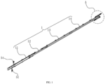
FIG. 1 is a schematic diagram of a structure of an inner burr removal tool holder structure according to the present disclosure; -
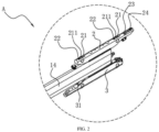
FIG. 2 is an enlarged schematic diagram of a position A inFIG. 1 ; -
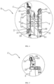
FIG. 3 is a schematic sectional view of an inner burr removal tool holder structure according to the present disclosure; -
FIG. 4 is an enlarged schematic diagram of a position B inFIG. 3 ; -
FIG. 5 is an enlarged schematic diagram of a position C inFIG. 4 ; -
FIG. 6 is an enlarged schematic diagram of a position D inFIG. 3 ; -
FIG. 7 is an installation top view of an inner burr removal tool holder structure according to the present disclosure; and -
FIG. 8 is an installation front view of an inner burr removal tool holder structure according to the present disclosure. - The reference numerals in the accompanying drawings are as follows.
1: connecting rod assembly; 11: first tool holder rod; 12: second tool holder rod; 121: first mounting base; 1211: first channel; 122: second mounting base; 1221: second channel; 13: third tool holder rod; 14: fourth tool holder rod; 2: tool base; 21: first roller; 211: annular relief slot; 22: first accommodation slot; 23: nozzle; 24: scraper; 25: stepped hole; 26: gasket; 3: roller base; 31: second roller; 32: second accommodation slot; 4: first water channel; 41: first water pipe; 42: third channel; 43: second water pipe; 5: second water channel; 51: water inlet pipe; 52: through channel; 53: cooling channel; 54: water outlet pipe; 6: magnetic rod; 61: protective sleeve; 7: tool rod mounting base; 71: height-adjusting structure; 711: sliding block; 712: adjusting base; 713: threaded rod; 714: rotating handle; 8: supporting base; 81: upper supporting wheel; 82: lower supporting wheel. - To make the solved technical problems, the technical solutions, and the beneficial effects in the present disclosure more comprehensible, the following further describes the present disclosure in detail with reference to the accompanying drawings and embodiments. It should be understood that the specific embodiments described herein are merely used for explaining the present disclosure instead of limiting the present disclosure.
- As shown in
FIG. 1 to FIG. 8 , an embodiment of the present disclosure provides an inner burr removal tool holder structure, including a tool holder body. The tool holder body includes atool base 2 and a connectingrod assembly 1. The connectingrod assembly 1 is connected to thetool base 2. Ascraper 24 for removing inner burrs and anozzle 23 for spraying liquid is arranged on thetool base 2. Thescraper 24 protrudes from an outer surface of thetool base 2, and a liquid outlet of thenozzle 23 faces thescraper 24. - As shown in
FIG. 2 andFIG. 5 , thenozzle 23 for spraying liquid is arranged on one side of thescraper 24, and when thenozzle 23 can perform an inner burr removal operation of a longitudinally welded pipe by using thescraper 24, cooling water is sprayed at a position of thescraper 24, so that burrs accumulated on thescraper 24 are dispersed, accumulation of burrs on thescraper 24 is avoided, burrs that are sprayed down flows out of the longitudinally welded pipe with the cooling water, and the cooling water also cools thescraper 24. This avoids performance deterioration caused by overheating of thescraper 24, and effectively improves a service life of thescraper 24. - As shown in
FIG. 5 , in this embodiment, a steppedhole 25 is provided in thetool base 2, and at least onegasket 26 is arranged on a stepped surface of the steppedhole 25. Thegasket 26 is a partial hollow-out structure, and thescraper 24 is an annular structure. Thescraper 24 is embedded in the steppedhole 25 and is abutted against thegasket 26, and thescraper 24 is partially exposed in the steppedhole 25. - The
gasket 26 is used for adjusting a height of thescraper 24 protruding from the steppedhole 25. Specifically, a thickness of thegasket 26 or a quantity of stacks can be adjusted to adjust a distance between thescraper 24 and the stepped surface of the steppedhole 25, and the protruding height of thescraper 24 can be adjusted, so that the inner burr removal tool holder structure adjusts an inner burr scraping height of a longitudinally welded pipe to improve adjustment accuracy. - Because the
scraper 24 is an annular structure, burrs scraped off by thescraper 24 may fall from the bottom of the steppedhole 25 through a middle hole of thescraper 24, to reduce a risk of burr accumulation. In addition, thegasket 26 is arranged as a partial hollow-out structure, so that blockage of the steppedhole 25 by burrs due to the use of thegasket 26 can be avoided. In different embodiments, thegasket 26 may be selected from a grid structure or another opening structure. - In this embodiment, the connecting
rod assembly 1 includes afirst water channel 4, thefirst water channel 4 extends along the connectingrod assembly 1, and thefirst water channel 4 is communicated with thenozzle 23. - As shown in
FIG. 4 , in this embodiment, afirst roller 21 protruding from the outer surface of thetool base 2 is arranged on thetool base 2, and anannular relief slot 211 is provided in an outer wall of thefirst roller 21 along a circumferential direction of thefirst roller 21. - The
first roller 21 is configured to be in contact with an inner wall of the longitudinally welded pipe to reduce frictional force of the tool holder body moving inside the longitudinally welded pipe. Because thefirst roller 21 is used as a support of thetool base 2, in a process of scraping off the inner burrs by using thescraper 24, thetool base 2 moves relative to the longitudinally welded pipe, thefirst roller 21 produces compressive force to a straight weld seam, and the straight weld seam that just be welded is fragile, so that the straight weld seam is easily crushed by thefirst roller 21. To solve the problem, theannular relief slot 211 is provided in the circumferential direction of thefirst roller 21, and in a process of rolling thefirst roller 21, theannular relief slot 211 is used for passage of the straight weld seam of the longitudinally welded pipe, to avoid an impact of thefirst roller 21 on the straight weld seam of the longitudinally welded pipe. - In this embodiment, there are a plurality of
first rollers 21, afirst accommodation slot 22 accommodating thefirst roller 21 is provided in the outer surface of thetool base 2, and two sides of thefirst roller 21 are rotatably connected to an inner wall of thefirst accommodation slot 22, to prevent thefirst roller 21 from excessively protruding from the outer surface of thetool base 2. - In this embodiment, the tool holder body further includes a
roller base 3. Thetool base 2 and theroller base 3 are respectively located at two sides of an end of the connectingrod assembly 1, and asecond roller 31 protruding from an outer surface of theroller base 3 is arranged on theroller base 3. - A function of the
second roller 31 is similar to that of thefirst roller 21, and thesecond roller 31 and thefirst roller 21 are both configured to be in contact with the inner wall of the longitudinally welded pipe to reduce the frictional force of the tool holder body moving inside the longitudinally welded pipe. Specifically, there are a plurality ofsecond rollers 31, asecond accommodation slot 32 accommodating thesecond roller 31 is provided in the outer surface of theroller base 3, and two sides of thesecond roller 31 are rotatably connected to an inner wall of thesecond accommodation slot 32, to prevent thesecond roller 31 from excessively protruding from the outer surface of theroller base 3. - As shown in
FIG. 3 , in this embodiment, the connectingrod assembly 1 includes a firsttool holder rod 11, a secondtool holder rod 12, a thirdtool holder rod 13, and a fourthtool holder rod 14. The firsttool holder rod 11, the secondtool holder rod 12, the thirdtool holder rod 13, and the fourthtool holder rod 14 are connected end-to-end in sequence. Thetool base 2 is arranged at an end of the fourthtool holder rod 14. Specifically, thetool base 2 and theroller base 3 are respectively located at two sides of the end of the fourthtool holder rod 14. - The first
tool holder rod 11, the secondtool holder rod 12, the thirdtool holder rod 13, and the fourthtool holder rod 14 extend along a straight line. The firsttool holder rod 11, the secondtool holder rod 12, the thirdtool holder rod 13, and the fourthtool holder rod 14 are matched in a concave-convex structure, and are fastened and connected by using screws. - As shown in
FIG. 6 , amagnetic rod 6 is arranged on the secondtool holder rod 12, and themagnetic rod 6 extends along an outer wall of the secondtool holder rod 12. - The
magnetic rod 6 is used as an impedor, and when a welding operation of the longitudinally welded pipe is performed, themagnetic rod 6 may be moved to a corresponding position of an induction coil. The operation is used to cancel an impact of part of high-frequency induced magnetic fields generated by the induction coil on the secondtool holder rod 12, to avoid overheating and melting of the secondtool holder rod 12. - In this embodiment, the connecting
rod assembly 1 further includes asecond water channel 5, and thesecond water channel 5 flows through themagnetic rod 6. - In the welding operation of the longitudinally welded pipe, a temperature of a welding position is high, if a problem of overheating occurs on the
magnetic rod 6, themagnetic rod 6 is damaged. Themagnetic rod 6 is cooled down by setting thesecond water channel 5, so that a problem that a temperature of themagnetic rod 6 is excessively high is avoided. - In this embodiment, the
second water channel 5 includes awater inlet pipe 51, a throughchannel 52, a coolingchannel 53, and awater outlet pipe 54. Aprotective sleeve 61 is arranged outside themagnetic rod 6, an inner wall of theprotective sleeve 61 and an outer wall of themagnetic rod 6 constitute the coolingchannel 53. Theprotective sleeve 61 has a good protective effect on themagnetic rod 6, so that an abrasion of themagnetic rod 6 in a moving process of the longitudinally welded pipe is avoided, and an impact of falling welding liquid on themagnetic rod 6 is also avoided. Theprotective sleeve 61 is selected from an epoxy resin pipe and has good heat resistance. Thewater inlet pipe 51 and thewater outlet pipe 54 are arranged on the firsttool holder rod 11. The throughchannel 52 is arranged inside the secondtool holder rod 12. Thewater inlet pipe 51 is communicated with the throughchannel 52, the throughchannel 52 is communicated with the coolingchannel 53, and the coolingchannel 53 is communicated with thewater outlet pipe 54. When cooling water is inlet, the cooling water enters the throughchannel 52 from thewater inlet pipe 51, then flows into the coolingchannel 53 through the throughchannel 52, plays a role of heat exchange and cooling on themagnetic rod 6 in the coolingchannel 53, and is discharged through thewater outlet pipe 54 to achieve cooling of themagnetic rod 6. - Specifically, the
water inlet pipe 51 and thewater outlet pipe 54 are respectively arranged on outer walls of two sides of the firsttool holder rod 11, and extension directions of thewater inlet pipe 51 and thewater outlet pipe 54 are consistent with the length direction of the firsttool holder rod 11. One end of thewater inlet pipe 51 is introduced from one end on the firsttool holder rod 11 away from the secondtool holder rod 12, and the other end of thewater inlet pipe 51 extends to the secondtool holder rod 12 and is communicated with the throughchannel 52. Afirst mounting base 121 and asecond mounting base 122 are arranged on the secondtool holder rod 12, and thefirst mounting base 121 and thesecond mounting base 122 are spaced apart from each other. Two ends of theprotective sleeve 61 are connected to thefirst mounting base 121 and thesecond mounting base 122 via a sealing ring. Afirst channel 1211 for communicating the throughchannel 52 and the coolingchannel 53 is arranged inside thefirst mounting base 121. Asecond channel 1221 for communicating the coolingchannel 53 and thewater outlet pipe 54 is arranged inside thesecond mounting base 122. One end of thewater outlet pipe 54 is connected to thesecond mounting base 122, and the other end of thewater outlet pipe 54 extends to one end on the firsttool holder rod 11 away from the secondtool holder rod 12, and is led out. - As shown in
FIG. 4 andFIG. 6 , in this embodiment, thefirst water channel 4 is led out from thesecond water channel 5. Specifically, thefirst water channel 4 includes a first water pipe 41, a third channel 42, and a second water pipe 43. The first water pipe 41 is led out from thefirst channel 1211 on thefirst mounting base 121 and extends along outer walls of the thirdtool holder rod 13 and the fourthtool holder rod 14. The third channel 42 is arranged at an end of the fourthtool holder rod 14 away from the thirdtool holder rod 13. The first water pipe 41 is communicated with the third channel 42. The second water pipe 43 is separately communicated with the third channel 42 and thenozzle 23. - As shown in
FIG. 7 andFIG. 8 , the inner burr removal tool holder structure further includes a tool rod mounting base 7 and a supporting base 8. An end of the connectingrod assembly 1 away from thetool base 2 is fixed on the tool rod mounting base 7. A height-adjustingstructure 71 for adjusting a height is arranged on the tool rod mounting base 7. The supporting base 8 is configured to support a longitudinally welded pipe to allow for insertion of thetool base 2. - When an inner burr removal operation of the longitudinally welded pipe is performed, the longitudinally welded pipe may be placed on the supporting base 8 and the
tool base 2 may be extended into the longitudinally welded pipe. Heights of the connectingrod assembly 1 and thetool base 2 are adjusted by the height-adjustingstructure 71, so that thescraper 24 on thetool base 2 is in contact with a straight weld seam of the longitudinally welded pipe. Thescraper 24 is moved relative to the longitudinally welded pipe by driving the longitudinally welded pipe forward, so that the inner burrs in the longitudinally welded pipe are scraped off. - Specifically, the height-adjusting
structure 71 includes a sliding block 711, an adjustingbase 712, a threadedrod 713, and arotating handle 714. The sliding block 711 is fixed at the end of the connectingrod assembly 1 away from thetool base 2. The sliding block 711 is arranged on the adjustingbase 712 in a vertically slidable manner. The threadedrod 713 is rotatably connected to the adjustingbase 712, and the threadedrod 713 passes through the sliding block 711 and is threadedly fitted with the sliding block 711. Therotating handle 714 is connected to the threadedrod 713. When heights of the connectingrod assembly 1 and thetool base 2 need to be adjusted, therotating handle 714 can be rotated to implement height adjustment via the threaded fit between the threadedrod 713 and the sliding block 711. - A plurality of upper supporting
wheels 81 and a plurality of lower supportingwheels 82 are arranged on the supporting base 8, and the upper supportingwheels 81 and the lower supportingwheels 82 are spaced apart from each other in the vertical direction to support the longitudinally welded pipe in the middle of the upper supportingwheels 81 and the lower supportingwheels 82. - The foregoing descriptions are merely preferred embodiments of the present disclosure, but are not intended to limit the present disclosure. Any modification, equivalent replacement, or improvement made within the spirit and principle of the present disclosure shall fall within the protection scope of the present disclosure.
Claims (17)
- An inner burr removal tool holder structure, comprising a tool holder body, the tool holder body comprising a tool base (2) and a connecting rod assembly (1), the connecting rod assembly (1) being connected to the tool base (2), a scraper (24) for removing inner burrs and a nozzle (23) for spraying liquid being arranged on the tool base (2), the scraper (24) protruding from an outer surface of the tool base (2), and a liquid outlet of the nozzle (23) facing the scraper (24).
- The inner burr removal tool holder structure according to claim 1, wherein a stepped hole (25) is provided in the tool base (2), at least one gasket (26) is arranged on a stepped surface of the stepped hole (25), the gasket (26) is a partial hollow-out structure, the scraper (24) is an annular structure, the scraper (24) is embedded in the stepped hole (25) and is abutted against the gasket (26), and the scraper (24) is partially exposed in the stepped hole (25).
- The inner burr removal tool holder structure according to claim 1 or 2, wherein the connecting rod assembly (1) comprises a first water channel (4), the first water channel (4) extends along the connecting rod assembly (1), and the first water channel (4) is communicated with the nozzle (23).
- The inner burr removal tool holder structure according to any one of claims 1 to 3, wherein a first roller (21) protruding from the outer surface of the tool base (2) is arranged on the tool base (2), and an annular relief slot (211) is provided in an outer wall of the first roller (21) along a circumferential direction of the first roller (21).
- The inner burr removal tool holder structure according to claim 4, wherein there are a plurality of first rollers (21).
- The inner burr removal tool holder structure according to claim 4 or 5, wherein a first accommodation slot (22) accommodating the first roller (21) is provided in the outer surface of the tool base (2), and two sides of the first roller (21) are rotatably connected to an inner wall of the first accommodation slot (22).
- The inner burr removal tool holder structure according to any one of claims 1 to 6, wherein the tool holder body further comprises a roller base (3), the tool base (2) and the roller base (3) are respectively located at two sides of an end of the connecting rod assembly (1), and a second roller (31) protruding from an outer surface of the roller base (3) is arranged on the roller base (3).
- The inner burr removal tool holder structure according to claim 7, wherein there are a plurality of second rollers (31).
- The inner burr removal tool holder structure according to claim 7 or 8, wherein a second accommodation slot (32) accommodating the second roller (31) is provided in the outer surface of the roller base (3), and two sides of the second roller (31) are rotatably connected to an inner wall of the second accommodation slot (32).
- The inner burr removal tool holder structure according to any one of claims 1 to 9, wherein the connecting rod assembly (1) comprises a first tool holder rod (11), a second tool holder rod (12), a third tool holder rod (13), and a fourth tool holder rod (14), the first tool holder rod (11), the second tool holder rod (12), the third tool holder rod (13), and the fourth tool holder rod (14) are connected end-to-end in sequence, and the tool base (2) is arranged at an end of the fourth tool holder rod (14).
- The inner burr removal tool holder structure according to claim 10, wherein the first tool holder rod (11), the second tool holder rod (12), the third tool holder rod (13), and the fourth tool holder rod (14) extend along a straight line, and the first tool holder rod (11), the second tool holder rod (12), the third tool holder rod (13), and the fourth tool holder rod (14) are matched in a concave-convex structure, and are fastened and connected by using screws.
- The inner burr removal tool holder structure according to claim 10 or 11, wherein a magnetic rod (6) is arranged on the second tool holder rod (12), and the magnetic rod (6) extends along an outer wall of the second tool holder rod (12).
- The inner burr removal tool holder structure according to claim 12, wherein the connecting rod assembly (1) further comprises a second water channel (5), and the second water channel (5) flows through the magnetic rod (6).
- The inner burr removal tool holder structure according to claim 13, wherein the second water channel (5) comprises a water inlet pipe (51), a through channel (52), a cooling channel (53), and a water outlet pipe (54), a protective sleeve (61) is arranged outside the magnetic rod (6), an inner wall of the protective sleeve (61) and an outer wall of the magnetic rod (6) constitute the cooling channel (53), the water inlet pipe (51) and the water outlet pipe (54) are arranged on the first tool holder rod (11), the through channel (52) is arranged inside the second tool holder rod (12), the water inlet pipe (51) is communicated with the through channel (52), the through channel (52) is communicated with the cooling channel (53), and the cooling channel (53) is communicated with the water outlet pipe (54).
- The inner burr removal tool holder structure according to any one of claims 1 to 14, further comprising a tool rod mounting base (7) and a supporting base (8), an end of the connecting rod assembly (1) away from the tool base (2) being fixed on the tool rod mounting base (7), a height-adjusting structure (71) for adjusting a height being provided on the tool rod mounting base (7), and the supporting base (8) being configured to support a longitudinally welded pipe to allow for insertion of the tool base (2).
- The inner burr removal tool holder structure according to claim 15, wherein the height-adjusting structure (71) comprises a sliding block (711), an adjusting base (712), a threaded rod (713), and a rotating handle (714), the sliding block (711) is fixed at the end of the connecting rod assembly (1) away from the tool base (2), the sliding block (711) is arranged on the adjusting base (712) in a vertically slidable manner, the threaded rod (713) is rotatably connected to the adjusting base (712), the threaded rod (713) passes through the sliding block (711) and is threadedly fitted with the sliding block (711), the rotating handle (714) is connected to the threaded rod (713), and the rotating handle (714) can be rotated to implement height adjustments of the connecting rod assembly (1) and the tool base (2) via the threaded fit of the threaded rod (713) and the sliding block (711).
- The inner burr removal tool holder structure according to claim 15 or 16, wherein a plurality of upper supporting wheels (81) and a plurality of lower supporting wheels (82) are arranged on the supporting base (8), and the upper supporting wheels (81) and the lower supporting wheels (82) are spaced apart from each other in the vertical direction to support the longitudinally welded pipe.
Applications Claiming Priority (2)
| Application Number | Priority Date | Filing Date | Title |
|---|---|---|---|
| CN202122856618.6U CN216462246U (en) | 2021-11-19 | 2021-11-19 | An inner burr removal tool holder structure |
| PCT/CN2022/125886 WO2023088015A1 (en) | 2021-11-19 | 2022-10-18 | Inner burr removing knife rest structure |
Publications (2)
| Publication Number | Publication Date |
|---|---|
| EP4385650A1 true EP4385650A1 (en) | 2024-06-19 |
| EP4385650A4 EP4385650A4 (en) | 2024-12-04 |
Family
ID=81399004
Family Applications (1)
| Application Number | Title | Priority Date | Filing Date |
|---|---|---|---|
| EP22894552.3A Pending EP4385650A4 (en) | 2021-11-19 | 2022-10-18 | Inner burr removing knife rest structure |
Country Status (4)
| Country | Link |
|---|---|
| US (1) | US12599980B2 (en) |
| EP (1) | EP4385650A4 (en) |
| CN (1) | CN216462246U (en) |
| WO (1) | WO2023088015A1 (en) |
Families Citing this family (2)
| Publication number | Priority date | Publication date | Assignee | Title |
|---|---|---|---|---|
| CN216462246U (en) * | 2021-11-19 | 2022-05-10 | 比亚迪股份有限公司 | An inner burr removal tool holder structure |
| CN115478151A (en) * | 2022-10-08 | 2022-12-16 | 安徽楚江特钢有限公司 | A kind of production method of small diameter spinning head pipe |
Family Cites Families (18)
| Publication number | Priority date | Publication date | Assignee | Title |
|---|---|---|---|---|
| US3165028A (en) * | 1961-03-30 | 1965-01-12 | Yoder Co | Scarfing tool |
| FR1326161A (en) * | 1962-06-22 | 1963-05-03 | Apparatus for planing the welding rod inside a tube | |
| US3819898A (en) * | 1972-04-21 | 1974-06-25 | Olin Corp | Adjustable scarfing tool |
| JPS585122B2 (en) * | 1978-08-29 | 1983-01-29 | 日本鋼管株式会社 | Internal deburring, cleaning and coating equipment for pressure welding long medium and small diameter pipes |
| US4893972A (en) * | 1988-11-18 | 1990-01-16 | Pittsburgh Tube Company | Cutting tool |
| KR100682318B1 (en) * | 2004-12-04 | 2007-02-15 | 대주중공업주식회사 | Mild Steel Pipe Inner Bead Remover |
| US9895758B2 (en) * | 2014-03-18 | 2018-02-20 | Nakata Manufacturing Co., Ltd. | Ring tool unit, method for manufacturing the same, sleeve, and mandrel |
| CN104455168B (en) | 2014-11-24 | 2017-03-08 | 张家港保税区亚信汽车零部件科技有限公司 | A kind of low-frictional force cylinder barrel of amortisseur and its manufacture method |
| DE102015000797A1 (en) * | 2015-01-22 | 2016-07-28 | Heule Werkzeug Ag | Miniaturized deburring and / or chamfering tool with internal cooling |
| CN204997180U (en) | 2015-09-15 | 2016-01-27 | 江苏承中和高精度钢管制造有限公司 | Steel pipe removes interior burr device |
| CN105414672B (en) * | 2015-12-15 | 2017-12-15 | 淮安市贝克铝热传输有限公司 | A kind of ratio-frequency welding adapter lining inner burr removing apparatus |
| CN206578377U (en) * | 2017-03-21 | 2017-10-24 | 唐山正元管业有限公司 | Small-diameter welded pipes Removing of inner burs device |
| CN108856905A (en) | 2018-09-11 | 2018-11-23 | 金洲集团有限公司 | A kind of high-frequency welded steel pipe removes inner burr device online |
| CN209006691U (en) * | 2018-11-19 | 2019-06-21 | 广东大群数控机床有限公司 | A machine tool spindle with scraper |
| CN209288439U (en) * | 2018-12-10 | 2019-08-23 | 佛山市三水振鸿钢制品有限公司 | A high-frequency straight seam welded pipe online deburring equipment |
| CN110052665B (en) | 2019-05-08 | 2020-06-02 | 燕山大学 | A interior burr clearing device for permanent bottom surface shaping steel pipe |
| CN216462246U (en) * | 2021-11-19 | 2022-05-10 | 比亚迪股份有限公司 | An inner burr removal tool holder structure |
| JP2023180400A (en) * | 2022-06-09 | 2023-12-21 | 株式会社ディスコ | Burr removal equipment and cutting equipment |
-
2021
- 2021-11-19 CN CN202122856618.6U patent/CN216462246U/en active Active
-
2022
- 2022-10-18 WO PCT/CN2022/125886 patent/WO2023088015A1/en not_active Ceased
- 2022-10-18 EP EP22894552.3A patent/EP4385650A4/en active Pending
-
2024
- 2024-03-25 US US18/614,896 patent/US12599980B2/en active Active
Also Published As
| Publication number | Publication date |
|---|---|
| US20240227048A1 (en) | 2024-07-11 |
| WO2023088015A1 (en) | 2023-05-25 |
| CN216462246U (en) | 2022-05-10 |
| US12599980B2 (en) | 2026-04-14 |
| EP4385650A4 (en) | 2024-12-04 |
Similar Documents
| Publication | Publication Date | Title |
|---|---|---|
| US12599980B2 (en) | Inner burr removal tool holder structure | |
| JP6839210B2 (en) | Welding droplet shield device with integrated cleaning system | |
| CN107931737B (en) | Online deburring device for pipeline manufacturing | |
| CN215432794U (en) | Cooling nozzle convenient to angle of adjustment | |
| CN202726254U (en) | Tube penetrating line cutting device | |
| KR100592094B1 (en) | Pipe oil spill prevention device into pipe machine and molding pipe applied to it | |
| CN214978953U (en) | Pipeline welding aids with slag collection | |
| CN105414672A (en) | Device for cleaning burrs in high-frequency welding pipe | |
| CN110587084B (en) | Plasma powder surfacing welding gun with arc compression adjustment | |
| CN210314008U (en) | Glass-cutting tool bit and tool bit assembly | |
| KR20120124714A (en) | Sludge prevent device of forming machine | |
| CN216097865U (en) | Built-in cutting fluid cooling integrated device | |
| CN203778888U (en) | Cutter for removing burrs in welding steel pipes | |
| CN104889489A (en) | Metal pipe cutting device | |
| CN211028502U (en) | Walking driving device of gate type submerged arc welding machine | |
| CN212826178U (en) | Mortar curtain device of multi-guide-wheel wire cutting machine | |
| CN210254307U (en) | Floating boring cutter bar for deep hole | |
| CN211661274U (en) | Wire cutting machine molybdenum wire protection device and wire cutting machine | |
| CN210085993U (en) | Vibration bearing cooling and lubricating mechanism and vibration road roller | |
| CN211162585U (en) | Energy-saving efficient thin aluminum plate welding equipment | |
| CN217513509U (en) | A cylindrical grinding machine top cooling device | |
| CN119609703B (en) | Multifunctional hydraulic cylinder inner hole machining tool based on joint machining | |
| CN111215740A (en) | Resistance spot welding device | |
| CN205166062U (en) | Intraductal burr clearing device of high -frequency soldering | |
| CN206764016U (en) | A kind of band sawing machine with liquid withdrawal system |
Legal Events
| Date | Code | Title | Description |
|---|---|---|---|
| STAA | Information on the status of an ep patent application or granted ep patent |
Free format text: STATUS: THE INTERNATIONAL PUBLICATION HAS BEEN MADE |
|
| PUAI | Public reference made under article 153(3) epc to a published international application that has entered the european phase |
Free format text: ORIGINAL CODE: 0009012 |
|
| STAA | Information on the status of an ep patent application or granted ep patent |
Free format text: STATUS: REQUEST FOR EXAMINATION WAS MADE |
|
| 17P | Request for examination filed |
Effective date: 20240314 |
|
| AK | Designated contracting states |
Kind code of ref document: A1 Designated state(s): AL AT BE BG CH CY CZ DE DK EE ES FI FR GB GR HR HU IE IS IT LI LT LU LV MC ME MK MT NL NO PL PT RO RS SE SI SK SM TR |
|
| A4 | Supplementary search report drawn up and despatched |
Effective date: 20241105 |
|
| RIC1 | Information provided on ipc code assigned before grant |
Ipc: B23Q 11/10 20060101ALI20241029BHEP Ipc: B23D 79/02 20060101AFI20241029BHEP |
|
| DAV | Request for validation of the european patent (deleted) | ||
| DAX | Request for extension of the european patent (deleted) |