EP4385378A1 - Vacuum cleaner - Google Patents
Vacuum cleaner Download PDFInfo
- Publication number
- EP4385378A1 EP4385378A1 EP22213884.4A EP22213884A EP4385378A1 EP 4385378 A1 EP4385378 A1 EP 4385378A1 EP 22213884 A EP22213884 A EP 22213884A EP 4385378 A1 EP4385378 A1 EP 4385378A1
- Authority
- EP
- European Patent Office
- Prior art keywords
- intake means
- suction
- control unit
- vacuum cleaner
- cleaning
- Prior art date
- Legal status (The legal status is an assumption and is not a legal conclusion. Google has not performed a legal analysis and makes no representation as to the accuracy of the status listed.)
- Granted
Links
Images

Classifications
-
- B—PERFORMING OPERATIONS; TRANSPORTING
- B08—CLEANING
- B08B—CLEANING IN GENERAL; PREVENTION OF FOULING IN GENERAL
- B08B9/00—Cleaning hollow articles by methods or apparatus specially adapted thereto
- B08B9/02—Cleaning pipes or tubes or systems of pipes or tubes
- B08B9/027—Cleaning the internal surfaces; Removal of blockages
- B08B9/032—Cleaning the internal surfaces; Removal of blockages by the mechanical action of a moving fluid, e.g. by flushing
- B08B9/035—Cleaning the internal surfaces; Removal of blockages by the mechanical action of a moving fluid, e.g. by flushing by suction
-
- A—HUMAN NECESSITIES
- A47—FURNITURE; DOMESTIC ARTICLES OR APPLIANCES; COFFEE MILLS; SPICE MILLS; SUCTION CLEANERS IN GENERAL
- A47L—DOMESTIC WASHING OR CLEANING; SUCTION CLEANERS IN GENERAL
- A47L9/00—Details or accessories of suction cleaners, e.g. mechanical means for controlling the suction or for effecting pulsating action; Storing devices specially adapted to suction cleaners or parts thereof; Carrying-vehicles specially adapted for suction cleaners
- A47L9/0072—Mechanical means for controlling the suction or for effecting pulsating action
-
- A—HUMAN NECESSITIES
- A47—FURNITURE; DOMESTIC ARTICLES OR APPLIANCES; COFFEE MILLS; SPICE MILLS; SUCTION CLEANERS IN GENERAL
- A47L—DOMESTIC WASHING OR CLEANING; SUCTION CLEANERS IN GENERAL
- A47L9/00—Details or accessories of suction cleaners, e.g. mechanical means for controlling the suction or for effecting pulsating action; Storing devices specially adapted to suction cleaners or parts thereof; Carrying-vehicles specially adapted for suction cleaners
- A47L9/02—Nozzles
-
- A—HUMAN NECESSITIES
- A47—FURNITURE; DOMESTIC ARTICLES OR APPLIANCES; COFFEE MILLS; SPICE MILLS; SUCTION CLEANERS IN GENERAL
- A47L—DOMESTIC WASHING OR CLEANING; SUCTION CLEANERS IN GENERAL
- A47L9/00—Details or accessories of suction cleaners, e.g. mechanical means for controlling the suction or for effecting pulsating action; Storing devices specially adapted to suction cleaners or parts thereof; Carrying-vehicles specially adapted for suction cleaners
- A47L9/02—Nozzles
- A47L9/06—Nozzles with fixed, e.g. adjustably fixed brushes or the like
- A47L9/066—Nozzles with fixed, e.g. adjustably fixed brushes or the like with adjustably mounted brushes, combs, lips or pads; Height adjustment of nozzle or dust loosening tools
-
- A—HUMAN NECESSITIES
- A47—FURNITURE; DOMESTIC ARTICLES OR APPLIANCES; COFFEE MILLS; SPICE MILLS; SUCTION CLEANERS IN GENERAL
- A47L—DOMESTIC WASHING OR CLEANING; SUCTION CLEANERS IN GENERAL
- A47L9/00—Details or accessories of suction cleaners, e.g. mechanical means for controlling the suction or for effecting pulsating action; Storing devices specially adapted to suction cleaners or parts thereof; Carrying-vehicles specially adapted for suction cleaners
- A47L9/24—Hoses or pipes; Hose or pipe couplings
- A47L9/248—Parts, details or accessories of hoses or pipes
-
- A—HUMAN NECESSITIES
- A47—FURNITURE; DOMESTIC ARTICLES OR APPLIANCES; COFFEE MILLS; SPICE MILLS; SUCTION CLEANERS IN GENERAL
- A47L—DOMESTIC WASHING OR CLEANING; SUCTION CLEANERS IN GENERAL
- A47L9/00—Details or accessories of suction cleaners, e.g. mechanical means for controlling the suction or for effecting pulsating action; Storing devices specially adapted to suction cleaners or parts thereof; Carrying-vehicles specially adapted for suction cleaners
- A47L9/28—Installation of the electric equipment, e.g. adaptation or attachment to the suction cleaner; Controlling suction cleaners by electric means
- A47L9/2805—Parameters or conditions being sensed
-
- A—HUMAN NECESSITIES
- A47—FURNITURE; DOMESTIC ARTICLES OR APPLIANCES; COFFEE MILLS; SPICE MILLS; SUCTION CLEANERS IN GENERAL
- A47L—DOMESTIC WASHING OR CLEANING; SUCTION CLEANERS IN GENERAL
- A47L9/00—Details or accessories of suction cleaners, e.g. mechanical means for controlling the suction or for effecting pulsating action; Storing devices specially adapted to suction cleaners or parts thereof; Carrying-vehicles specially adapted for suction cleaners
- A47L9/28—Installation of the electric equipment, e.g. adaptation or attachment to the suction cleaner; Controlling suction cleaners by electric means
- A47L9/2836—Installation of the electric equipment, e.g. adaptation or attachment to the suction cleaner; Controlling suction cleaners by electric means characterised by the parts which are controlled
- A47L9/2842—Suction motors or blowers
-
- A—HUMAN NECESSITIES
- A47—FURNITURE; DOMESTIC ARTICLES OR APPLIANCES; COFFEE MILLS; SPICE MILLS; SUCTION CLEANERS IN GENERAL
- A47L—DOMESTIC WASHING OR CLEANING; SUCTION CLEANERS IN GENERAL
- A47L9/00—Details or accessories of suction cleaners, e.g. mechanical means for controlling the suction or for effecting pulsating action; Storing devices specially adapted to suction cleaners or parts thereof; Carrying-vehicles specially adapted for suction cleaners
- A47L9/28—Installation of the electric equipment, e.g. adaptation or attachment to the suction cleaner; Controlling suction cleaners by electric means
- A47L9/2857—User input or output elements for control, e.g. buttons, switches or displays
-
- B—PERFORMING OPERATIONS; TRANSPORTING
- B08—CLEANING
- B08B—CLEANING IN GENERAL; PREVENTION OF FOULING IN GENERAL
- B08B2209/00—Details of machines or methods for cleaning hollow articles
- B08B2209/02—Details of apparatuses or methods for cleaning pipes or tubes
- B08B2209/027—Details of apparatuses or methods for cleaning pipes or tubes for cleaning the internal surfaces
- B08B2209/032—Details of apparatuses or methods for cleaning pipes or tubes for cleaning the internal surfaces by the mechanical action of a moving fluid
Definitions
- the invention relates to an electric motor driven suction cleaning apparatus, more particularly to an electric vacuum cleaner comprising a suction nozzle or brush, a suction channel and means for collecting dust.
- a vacuum cleaner is an electric appliance that filters dust, dirt and foreign matters together with air into a body provided therein, after sucking them by using a vacuum motor mounted in the body.
- vacuum cleaners may be classified at least into a canister type having a suction nozzle or brush communicated with the body via a suction pipe or pipes and a flexible suction hose, wherein the body is equipped with wheels for moving the vacuum cleaner over the floor.
- a stick type vacuum cleaner having a suction nozzle that can be directly connected to the body o via a suction pipe or pipes, wherein the body is held in the user's hand during operation.
- Both types of the vacuum cleaners may include a vacuum cleaner body having a vacuum motor configured to generate a suction force mounted therein, a suction nozzle configured to suck dust and other rubbish scattered on a surface by the suction force generated in the body, and a connection pipe configured to connect the body and the suction nozzle with each other.
- the suction force enables the suction nozzle to suck therein the air containing dust and other rubbish scattered on the surface which will be cleaned.
- the air containing the dust and other rubbish may be drawn into the body via the connection pipe form the nozzle.
- the dust and other rubbish contained in the air sucked into the body may be separated within a dust separation means provided in the body, as a cyclonic separation apparatus or other means.
- the separated dust and other rubbish may be collected in a means for collecting dust that is in communication with the dust separation device and the air having the dust and foreign matters separated there from may be exhausted outside the body.
- cleaning parameters e.g. a suction power are reduce due to smaller airflow on some dense carpet. It causes that the dust and the other rubbish particles aren't sucked directly to means for collecting dust, but they levitate in the suction channel. It provides to bad cleaning effect, because when customer switch off the vacuum cleaner during appearing levitation phenomena then this particles haven't been vacuumed, but fall down again on the cleaned surface.
- Document GB2161902A discloses a non-return flap valve for a vacuum cleaner, comprising a movable sealing flap, a stationary part having means for mounting the non-return flap valve in a nozzle body of the vacuum cleaner, a strip connecting said flap to said stationary part and spacing said flap from said stationary part, and a constriction thickness across said strip, said constriction defining and extending along a flexing axis about which said flap articulates relative to said stationary part to prevent the dust and debris accumulated in a collecting chamber from escaping when the appliance is switched off, but unfortunately it does not prevent from falling out from the suction channel participles that are not accumulated in the said chamber.
- Document EP2113184A2 discloses a vacuum cleaner having a suction port and a suction channel, where a capacitive humidity sensor is arranged in the suction channel.
- the suction channel opens during detection of humidity in a secondary air opening that is spatially attached to the humidity sensor. Monitoring and/or cleaning agents in contact with the humidity sensor proceed during opening movement of the air opening.
- the air opening is obtained by opening a part of a suction channel wall to prevent water from being drawn into the vacuum cleaner.
- a locking position of the air opening is secured by magnets. The mentioned solution does not prevent from falling out participles form the suction channel, when the vacuuming is finished.
- a vacuum cleaner for cleaning a surface comprising: a body, an electrically-driven suction unit, a means for collecting the dust, a suction channel, a nozzle that is fluidly communicated with the body via the suction channel, an intake means fluidly communicated with the suction unit and provided for ensuring additional portion of the air in to the suction channel, and which can be adjusted between an opened state and a closed state, to open and close a by-pass channel, a control unit configured to control the suction unit, with a processor for storing, calculating and interpreting signals or data, and operated by a user a starting and stopping device being electrically communicated with the control unit and arranged to generate a cleaning start signal or a cleaning end signal.
- the intake means is bi-directionally electrically connected to the control unit, so transmission of data or signals between the intake means and the control unit is enabled, and the control unit is arranged to generate a signal for controlling the intake means in the event of detecting the cleaning start signal or the cleaning end signal.
- the vacuum cleaner is equipped with the intake means that is provided for ensuring an additional portion of air into the suction channel, also for reducing air flow resistance by the way of reduction of air suction resistance after the vacuum cleaner is switched off, i.e. when the user decides to finish cleaning the surface what is expressed by changing the state of the on/off switch. Then the additional portion of air can be sucked into the suction channel, and thus dust particles, which resided in the suction channel can be removed from the suction channel to the dust collecting means, thanks to which they do not fall out on the cleaned surface, what significantly improves the comfort and efficiency of cleaning.
- the intake means is arranged to generate data, that provide the control unit with information about the state of the intake means, wherein these data are used to control the suction unit by the control unit.
- the positive effect is that the control unit can adapt the control signals to the current state of the intake means.
- the intake means has an actuator, that is controlled by the control unit, wherein the actuator is configured to change the state of the intake means on the basis of the signal, therefore the state of the intake means can be changed automatically without the user intervention.
- the starting and stopping device is an electrical switch, wherein the switch is communicated with the control unit via a wired transmission.
- the intake means is configured to generate and send to the control unit the cleaning end signal for controlling the suction unit, when the intake means has been manually adjusted from the closed to the opened state by the user, wherein, then the suction unit is being switched off immediately or after calculated and counted predetermined time by the control unit.
- the positive effect is that the user can choose how to start cleaning the suction channel in the way by changing the state of the switch or by changing the state of the intake means, namely by changing it state from closed to opened state.
- the intake means comprises at least one paddle, that is arranged on a bottom of the nozzle, and the actuator which is configured to rotate the paddle between horizontal and vertical position and back in relation to the bottom of the nozzle in order to increase a gap between the bottom of the nozzle and the cleaned surface, when the intake means is in the opened state. Therefore, at least portion of the nozzle is lifted above the cleaned surface and therefore more air can be sucked into the inlet to remove from the suction channel residual dust participles by the increased gap.
- a vacuum cleaner has also a suction pipe that forms at least portion of the suction channel, and in that the intake means comprises a sleeve which slides on the outer surface of the suction pipe, an opening arranged in the suction pipe, wherein the sleeve is configured to air tightly close or open the opening when sliding along the suction pipe.
- the sleeve is provided with a handle which projects transversely from an outer surface of the sleeve to the movement of the sleeve.
- the intake means comprises a solenoid valve configured to be operated by the control unit, wherein the solenoid valve is arranged in the nozzle and is fluidly connected with the suction channel and is configured to allow inlet air to bypass a nozzle inlet.
- a method for operating the vacuum cleaner more particularly method for cleaning the suction channel according to the present invention comprises the following method steps, wherein the method is performed just after the user finishes cleaning the surface.
- the intake means is in the closed state, so the suction channel is provided with air merely via the inlet of the nozzle.
- the method of cleaning the suction channel is started when a state of the starting and stopping device is changed from on to off position and the cleaning end signal is sent to the control unit, then the suction unit is switched off by the control unit, immediately or alternatively is switched off after the calculated and counted time has elapsed.
- the control unit generates the signal and sends it to the intake means. Based on the signal the intake means changes the state from the closed state to the opened state.
- the control unit switches off the suction unit.
- the user is informed about the end of the cleaning process.
- intake means is operated to the closed state manually by the user or automatically by the control unit which generates and sends a signal to the intake means that is configured to be actuated.
- a method for operating the vacuum cleaner in order to clean the suction channel comprises the following method steps.
- the method for cleaning the suction channel is performed just after the user finishes cleaning the surface.
- the intake means is in the closed state.
- the method of cleaning the suction channel is started when the user manually changes the state of the intake means from the closed to the opened state, then the intake means generates and sends the cleaning end signal to the control unit, to start counting time for switching off the suction unit, or alternatively the suction unit is switched off immediately when the intake means changed the state.
- the control unit switches off the suction unit.
- the user is informed about the end of the cleaning process.
- intake means is operated to the closed state manually by the user or automatically by the control unit which generates and sends a signal to the intake means that is configured to be actuated.
- FIG. 1 is a schematic view of the vacuum cleaner according to the present invention.
- a vacuum cleaner 1 for cleaning a surface 13 has a body 2, an electrically-driven suction unit 3, a means for collecting the dust 4, a suction channel 5, a nozzle 6 that is fluidly communicated with the body 2 via the suction channel 5, an intake means 7 with a by-pass 18 fluidly communicated with the suction unit 3 via suction channel 5, and provided for ensuring additional portion of the air in to the suction channel 5, and which can be adjusted between an opened state and a closed state, to open and close the by-pass channel 18.
- the vacuum cleaner 1 also has a control unit 8 configured to control the suction unit 3, with a processor for storing, calculating and interpreting signals or data, and operated by the user a starting and stopping device 9, being electrically communicated with the control unit 8 and arranged to generate a cleaning start signal or a cleaning end signal SE. Furtherly, the intake means 7 is also adapted to generate the cleaning end signal SE, which initiates the method of cleaning the suction channel 5.
- the intake means 7 is bi-directionally electrically connected to the control unit 8, in order to transmit data or signals between the intake means 7 and the control unit 8.
- the control unit 8 In the first case, in the event of detecting the cleaning end signal SE, the control unit 8 generates a signal S1 to change the state of the intake means 7 from the closed to the opened by using an actuator 10, and starts counting time to switch off from the supply the suction unit 3, or alternatively suction unit 3 is switch off immediately, and dust participles are sucked in to the means for collecting the dust 4.
- the intake means 7 If the user decides to use the intake means to start the cleaning suction channel 5 method, he changes the state of it from closed to opened state, then the intake means 7 generates the cleaning end signal SE for the control unit 8 which starts calculating time to switch off from the supply the suction unit 3, or alternatively suction unit 3 is switch off immediately, and dust participles are sucked in to the means for collecting the dust 4, by the momentum of the suction unit 3.
- the control unit 8 informs the user about the end of the cleaning process of the suction channel 5, and the intake means 7 is operated to the closed state, manually by the user or automatically by the control unit 8 which generates and sends a signal S2 to the intake means 7 to be actuated to the closed state by the actuator 10.
- FIG. 2 shows the preferred embodiment of the vacuum cleaner.
- a vacuum cleaner 1 for cleaning a surface 13 has a body 2 with an electrically-driven suction unit 3 (not shown), a means for collecting the dust 4, and a nozzle 6 for cleaning the surface 13, that is fluidly connected with the body 2 via a suction pipe 16 and forming together the suction channel 5.
- the nozzle 6 has an inlet 17 (not shown) arranged on the bottom side of it and an intake means 7 that is arranged on the upper portion of the nozzle 6.
- the intake means 7 is a valve with an actuator 10 for opening and closing it.
- the valve has a by-pass channel 18 which is fluidly communicated with the suction channel 5 and provided for ensuring additional portion of air into the suction channel in order to bypass the inlet 17.
- the vacuum cleaner 1 also comprises a control unit 8 (not shown) and a starting and stopping device 9, which is in the form of an on/off electrical switch connected to the control unit 8 by wires.
- the control unit 8 has a processor for storing, calculating and interpreting signals or data is configured to control the suction unit 3 and the intake means 7. While cleaning the surface 13, the switch is on and the valve is closed, therefore air is sucked into the suction channel 5 only through the inlet 17.
- the switch state change is transmitted to the control unit 8 which changes the state of the valve to open the by-pass channel 18 and starts calculating time to switch off from the supply the suction unit 3, or alternatively suction unit 3 is switch off immediately, and dust participles are sucked from the suction channel into the means for collecting the dust 4.
- the control unit 8 informs the user about the end of the cleaning process of the suction channel 5, and the control unit 8 generates and sends a signal S2 to the actuator 10 to close the valve.
- FIG. 3 shows the another preferred embodiment of the vacuum cleaner.
- a vacuum cleaner 1 for cleaning a surface 13 has a body 2 with an electrically-driven suction unit 3 (not shown), a means for collecting the dust 4, and a nozzle 6 for cleaning the surface 13, that is fluidly connected with the body 2 via a suction pipe 16 which forming together the suction channel 5.
- the nozzle 6 has an inlet 17 (not shown) arranged on the bottom side of it.
- the vacuum cleaner 1 also comprises an intake means 7 which is arranged on the suction pipe 16.
- the intake means 7 has a sleeve 13 which slides on the outer surface of the suction pipe 16, an opening 14 arranged in the suction pipe 16, wherein the sleeve 13 is configured to air tightly close or open the opening 14, when sliding along the suction pipe 16.
- the sleeve 13 is provided with a handle 15 which projects from an outer surface of the sleeve 13 transversely to the movement of the sleeve 13.
- the vacuum cleaner 1 also comprises a control unit 8 (not shown) and a starting and stopping device 9 which is in the form of an on/off electrical switch connected to the control unit 8 by wires.
- the control unit 8 has a processor for storing, calculating and interpreting signals or data is configured to control the suction unit 3 and the intake means 7.
- the switch While cleaning the surface 13, the switch is on and the opening 14 is covered by the sleeve 13, therefore air is sucked only through the inlet 17, into the suction channel 5.
- the user decides to finish cleaning the surface 13, he presses the handle 15 of the sleeve 13, in this way the sleeve 13 slides along the suction pipe 16 and the opening 14 is no longer covered by the sleeve 13.
- the intake means 7 send the signal SE to the control unit 8, which starts calculating time to switch off the suction unit 3 from the supply, or alternatively the suction unit 3 is switch off immediately, and dust participles are sucked from the suction channel into the means for collecting the dust 4 with the help from the additional portion of air sucked via the opening 14.
- the control unit 8 informs the user about the end of the cleaning process of the suction channel 5. Then, the user moves back the sleeve 13 to cover the opening 14.
- FIG. 4 shows the another preferred embodiment of a vacuum cleaner in fragmentary view.
- a vacuum cleaner 1 for cleaning a surface 13 has a body 2 (not shown) with an electrically-driven suction unit 3 (not shown), a means for collecting the dust 4 (not shown), and a nozzle 6 for cleaning the surface 13, that is fluidly connected with the body 2 via a suction pipe 16 and forming together the suction channel 5.
- the nozzle 6 has an inlet 17 arranged on the bottom side of it.
- the vacuum cleaner 1 also comprises an intake means 7 that is arranged at the bottom side of the nozzle 6.
- the intake means 7 comprises at least one paddle 11, that is pivotally arranged on the bottom of the nozzle 6, and the actuator 10 which is configured to rotate the paddle 11 between horizontal and vertical position about a pivot axis lying on the bottom of the nozzle 6, in order to increase a gap 12 between the bottom of the nozzle 6 and the cleaned surface 13, when the intake means 7 is in the opened state.
- the vacuum cleaner 1 has a control unit 8 (not shown) and a starting and stopping device 9 which is in the form of an on/off electrical switch connected to the control unit 8 by wires.
- the control unit 8 has a processor for storing, calculating and interpreting signals or data is configured to control the suction unit 3 and the intake means 7.
- the switch While cleaning the surface 13, the switch is on and the paddle 11 stays horizontally to the surface 13 and is hidden in the bottom of the nozzle 6, therefore air is sucked into the suction channel only through the very small gap 12 into the inlet 17.
- the control unit 8 If the user decides to finish cleaning of the surface 13 process, he changes the state of the switch from on to off, change of the state of the switch is transmitted to the control unit 8, then the control unit 8 send the signal S1 to the intake means 7 to move the paddle 11 from horizontal to vertical position.
- the actuator 10 rotates the paddle 11, therefore the gap 12 is increased, that allows more air to be drawn into the suction channel 5.
- control unit 8 starts calculating time to switch off the suction unit 3 from the supply, or alternatively suction unit 3 is switch off immediately, and dust participles are sucked from the suction channel into the means for collecting the dust 4 by a momentum of the suction unit 3.
- the control unit 8 informs the user about the end of the cleaning process of the suction channel 5, and the control unit 8 generates and sends a signal S2 to the actuator 10 which rotates the paddle 11 back to its initial horizontal position.
Landscapes
- Engineering & Computer Science (AREA)
- Mechanical Engineering (AREA)
- Nozzles For Electric Vacuum Cleaners (AREA)
Abstract
Description
- The invention relates to an electric motor driven suction cleaning apparatus, more particularly to an electric vacuum cleaner comprising a suction nozzle or brush, a suction channel and means for collecting dust.
- A vacuum cleaner is an electric appliance that filters dust, dirt and foreign matters together with air into a body provided therein, after sucking them by using a vacuum motor mounted in the body.
- Generally, vacuum cleaners may be classified at least into a canister type having a suction nozzle or brush communicated with the body via a suction pipe or pipes and a flexible suction hose, wherein the body is equipped with wheels for moving the vacuum cleaner over the floor. Another type of vacuum cleaners is a stick type vacuum cleaner having a suction nozzle that can be directly connected to the body o via a suction pipe or pipes, wherein the body is held in the user's hand during operation.
- Both types of the vacuum cleaners may include a vacuum cleaner body having a vacuum motor configured to generate a suction force mounted therein, a suction nozzle configured to suck dust and other rubbish scattered on a surface by the suction force generated in the body, and a connection pipe configured to connect the body and the suction nozzle with each other.
- The suction force enables the suction nozzle to suck therein the air containing dust and other rubbish scattered on the surface which will be cleaned.
- The air containing the dust and other rubbish may be drawn into the body via the connection pipe form the nozzle. The dust and other rubbish contained in the air sucked into the body may be separated within a dust separation means provided in the body, as a cyclonic separation apparatus or other means.
- After that, the separated dust and other rubbish may be collected in a means for collecting dust that is in communication with the dust separation device and the air having the dust and foreign matters separated there from may be exhausted outside the body.
- Customers uses the vacuum cleaner on many different surfaces and carpets. For some of them, cleaning parameters, e.g. a suction power are reduce due to smaller airflow on some dense carpet. It causes that the dust and the other rubbish particles aren't sucked directly to means for collecting dust, but they levitate in the suction channel. It provides to bad cleaning effect, because when customer switch off the vacuum cleaner during appearing levitation phenomena then this particles haven't been vacuumed, but fall down again on the cleaned surface.
- Document
GB2161902A - Document
EP2113184A2 discloses a vacuum cleaner having a suction port and a suction channel, where a capacitive humidity sensor is arranged in the suction channel. The suction channel opens during detection of humidity in a secondary air opening that is spatially attached to the humidity sensor. Monitoring and/or cleaning agents in contact with the humidity sensor proceed during opening movement of the air opening. The air opening is obtained by opening a part of a suction channel wall to prevent water from being drawn into the vacuum cleaner. A locking position of the air opening is secured by magnets. The mentioned solution does not prevent from falling out participles form the suction channel, when the vacuuming is finished. - This is an object of the invention to collect all the residual dust and other rubbish in the suction channel at means for collecting dust of a body when the vacuuming is finished in order to improve the comfort and performance of the cleaning.
- In accordance with the present invention, there is provided a vacuum cleaner for cleaning a surface, comprising: a body, an electrically-driven suction unit, a means for collecting the dust, a suction channel, a nozzle that is fluidly communicated with the body via the suction channel, an intake means fluidly communicated with the suction unit and provided for ensuring additional portion of the air in to the suction channel, and which can be adjusted between an opened state and a closed state, to open and close a by-pass channel, a control unit configured to control the suction unit, with a processor for storing, calculating and interpreting signals or data, and operated by a user a starting and stopping device being electrically communicated with the control unit and arranged to generate a cleaning start signal or a cleaning end signal. The intake means is bi-directionally electrically connected to the control unit, so transmission of data or signals between the intake means and the control unit is enabled, and the control unit is arranged to generate a signal for controlling the intake means in the event of detecting the cleaning start signal or the cleaning end signal.
- Advantageously, the vacuum cleaner is equipped with the intake means that is provided for ensuring an additional portion of air into the suction channel, also for reducing air flow resistance by the way of reduction of air suction resistance after the vacuum cleaner is switched off, i.e. when the user decides to finish cleaning the surface what is expressed by changing the state of the on/off switch. Then the additional portion of air can be sucked into the suction channel, and thus dust particles, which resided in the suction channel can be removed from the suction channel to the dust collecting means, thanks to which they do not fall out on the cleaned surface, what significantly improves the comfort and efficiency of cleaning.
- In a preferred embodiment of the invention the intake means is arranged to generate data, that provide the control unit with information about the state of the intake means, wherein these data are used to control the suction unit by the control unit. The positive effect is that the control unit can adapt the control signals to the current state of the intake means.
- Preferable the intake means has an actuator, that is controlled by the control unit, wherein the actuator is configured to change the state of the intake means on the basis of the signal, therefore the state of the intake means can be changed automatically without the user intervention.
- In the another preferred embodiment of the invention the starting and stopping device is an electrical switch, wherein the switch is communicated with the control unit via a wired transmission. Such solution is cheap to use and reliable to operate.
- Advantageously the intake means is configured to generate and send to the control unit the cleaning end signal for controlling the suction unit, when the intake means has been manually adjusted from the closed to the opened state by the user, wherein, then the suction unit is being switched off immediately or after calculated and counted predetermined time by the control unit. The positive effect is that the user can choose how to start cleaning the suction channel in the way by changing the state of the switch or by changing the state of the intake means, namely by changing it state from closed to opened state.
- In a preferred embodiment of the invention the intake means comprises at least one paddle, that is arranged on a bottom of the nozzle, and the actuator which is configured to rotate the paddle between horizontal and vertical position and back in relation to the bottom of the nozzle in order to increase a gap between the bottom of the nozzle and the cleaned surface, when the intake means is in the opened state. Therefore, at least portion of the nozzle is lifted above the cleaned surface and therefore more air can be sucked into the inlet to remove from the suction channel residual dust participles by the increased gap.
- In another preferred embodiment a vacuum cleaner has also a suction pipe that forms at least portion of the suction channel, and in that the intake means comprises a sleeve which slides on the outer surface of the suction pipe, an opening arranged in the suction pipe, wherein the sleeve is configured to air tightly close or open the opening when sliding along the suction pipe. Preferable the sleeve is provided with a handle which projects transversely from an outer surface of the sleeve to the movement of the sleeve. The positive effect is that the inlet means can be operated by the user both by the hand or the foot, and the solution itself is uncomplicated, reliable and easy to use in production.
- Preferable the intake means comprises a solenoid valve configured to be operated by the control unit, wherein the solenoid valve is arranged in the nozzle and is fluidly connected with the suction channel and is configured to allow inlet air to bypass a nozzle inlet.
- A method for operating the vacuum cleaner more particularly method for cleaning the suction channel according to the present invention comprises the following method steps, wherein the method is performed just after the user finishes cleaning the surface. During the cleaning the surface the intake means is in the closed state, so the suction channel is provided with air merely via the inlet of the nozzle. The method of cleaning the suction channel is started when a state of the starting and stopping device is changed from on to off position and the cleaning end signal is sent to the control unit, then the suction unit is switched off by the control unit, immediately or alternatively is switched off after the calculated and counted time has elapsed. The control unit generates the signal and sends it to the intake means. Based on the signal the intake means changes the state from the closed state to the opened state. After the predetermined time, that is calculated by the processor, the control unit switches off the suction unit. The user is informed about the end of the cleaning process. Then, intake means is operated to the closed state manually by the user or automatically by the control unit which generates and sends a signal to the intake means that is configured to be actuated.
- In another embodiment a method for operating the vacuum cleaner in order to clean the suction channel, comprises the following method steps. The method for cleaning the suction channel is performed just after the user finishes cleaning the surface. During the cleaning the surface the intake means is in the closed state. The method of cleaning the suction channel is started when the user manually changes the state of the intake means from the closed to the opened state, then the intake means generates and sends the cleaning end signal to the control unit, to start counting time for switching off the suction unit, or alternatively the suction unit is switched off immediately when the intake means changed the state. After the counted time, that is calculated by the processor has elapsed, the control unit switches off the suction unit. The user is informed about the end of the cleaning process. Then, intake means is operated to the closed state manually by the user or automatically by the control unit which generates and sends a signal to the intake means that is configured to be actuated.
- Further benefits and advantages of the present invention will become apparent after a careful reading of the detailed description with appropriate reference to the accompanying drawings.
- In the drawings:
-
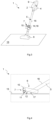
Fig. 1 shows a schematic view of the vacuum cleaner according to the present invention, -
Fig. 2 is a perspective view of a vacuum cleaner with the preferred embodiment of the present invention, -
Fig. 3 is a perspective view of a vacuum cleaner according to another preferred embodiment of the invention, -
Fig. 4 is a fragmentary plain view of a vacuum cleaner according to another preferred embodiment of the invention, - In cooperation with attached drawing, the technical contents and detailed description of the present invention are described thereinafter according to a preferable embodiment being not used to limit its executing scope. Any equivalent variation and modification made according to appended claims is all covered by the claims claimed by the present invention. In the following description of the preferred embodiments of the present invention, similar identical reference numbers designate identical of comparable components.
- Reference will now be made to the drawing figures to describe the present invention in detail.
- Reference is made to
Fig. 1 which is a schematic view of the vacuum cleaner according to the present invention. Avacuum cleaner 1 for cleaning asurface 13 has abody 2, an electrically-drivensuction unit 3, a means for collecting thedust 4, asuction channel 5, anozzle 6 that is fluidly communicated with thebody 2 via thesuction channel 5, an intake means 7 with a by-pass 18 fluidly communicated with thesuction unit 3 viasuction channel 5, and provided for ensuring additional portion of the air in to thesuction channel 5, and which can be adjusted between an opened state and a closed state, to open and close the by-pass channel 18. When the intake means 7 is in the opened state, the additional portion of air is sucked via the by-pass channel 18, what ensures better circulation of the air in thesuction channel 5, so dust participles that levitate inside thesuction channel 5 are sucked into the means for collecting thedust 4. Thevacuum cleaner 1, also has acontrol unit 8 configured to control thesuction unit 3, with a processor for storing, calculating and interpreting signals or data, and operated by the user a starting and stoppingdevice 9, being electrically communicated with thecontrol unit 8 and arranged to generate a cleaning start signal or a cleaning end signal SE. Furtherly, the intake means 7 is also adapted to generate the cleaning end signal SE, which initiates the method of cleaning thesuction channel 5. Therefore, the user can choose how to start the process of cleaning thesuction channel 5. The intake means 7 is bi-directionally electrically connected to thecontrol unit 8, in order to transmit data or signals between the intake means 7 and thecontrol unit 8. At the moment, when the user decides to finish cleaning thesurface 13, he changes the state of the starting and stoppingdevice 9 or alternatively changes the state of the intake means 7. In the first case, in the event of detecting the cleaning end signal SE, thecontrol unit 8 generates a signal S1 to change the state of the intake means 7 from the closed to the opened by using anactuator 10, and starts counting time to switch off from the supply thesuction unit 3, or alternativelysuction unit 3 is switch off immediately, and dust participles are sucked in to the means for collecting thedust 4. If the user decides to use the intake means to start thecleaning suction channel 5 method, he changes the state of it from closed to opened state, then the intake means 7 generates the cleaning end signal SE for thecontrol unit 8 which starts calculating time to switch off from the supply thesuction unit 3, or alternativelysuction unit 3 is switch off immediately, and dust participles are sucked in to the means for collecting thedust 4, by the momentum of thesuction unit 3. Thecontrol unit 8 informs the user about the end of the cleaning process of thesuction channel 5, and the intake means 7 is operated to the closed state, manually by the user or automatically by thecontrol unit 8 which generates and sends a signal S2 to the intake means 7 to be actuated to the closed state by theactuator 10. -
Fig. 2 shows the preferred embodiment of the vacuum cleaner. Avacuum cleaner 1 for cleaning asurface 13 has abody 2 with an electrically-driven suction unit 3 (not shown), a means for collecting thedust 4, and anozzle 6 for cleaning thesurface 13, that is fluidly connected with thebody 2 via asuction pipe 16 and forming together thesuction channel 5. Thenozzle 6 has an inlet 17 (not shown) arranged on the bottom side of it and an intake means 7 that is arranged on the upper portion of thenozzle 6. The intake means 7 is a valve with anactuator 10 for opening and closing it. The valve has a by-pass channel 18 which is fluidly communicated with thesuction channel 5 and provided for ensuring additional portion of air into the suction channel in order to bypass theinlet 17. Thevacuum cleaner 1 also comprises a control unit 8 (not shown) and a starting and stoppingdevice 9, which is in the form of an on/off electrical switch connected to thecontrol unit 8 by wires. Thecontrol unit 8 has a processor for storing, calculating and interpreting signals or data is configured to control thesuction unit 3 and the intake means 7. While cleaning thesurface 13, the switch is on and the valve is closed, therefore air is sucked into thesuction channel 5 only through theinlet 17. If the user decides to finish this process he changes the state of the switch from on to off, the switch state change is transmitted to thecontrol unit 8 which changes the state of the valve to open the by-pass channel 18 and starts calculating time to switch off from the supply thesuction unit 3, or alternativelysuction unit 3 is switch off immediately, and dust participles are sucked from the suction channel into the means for collecting thedust 4. Thecontrol unit 8 informs the user about the end of the cleaning process of thesuction channel 5, and thecontrol unit 8 generates and sends a signal S2 to theactuator 10 to close the valve. -
Fig. 3 shows the another preferred embodiment of the vacuum cleaner. Avacuum cleaner 1 for cleaning asurface 13 has abody 2 with an electrically-driven suction unit 3 (not shown), a means for collecting thedust 4, and anozzle 6 for cleaning thesurface 13, that is fluidly connected with thebody 2 via asuction pipe 16 which forming together thesuction channel 5. Thenozzle 6 has an inlet 17 (not shown) arranged on the bottom side of it. Thevacuum cleaner 1 also comprises an intake means 7 which is arranged on thesuction pipe 16. The intake means 7 has asleeve 13 which slides on the outer surface of thesuction pipe 16, anopening 14 arranged in thesuction pipe 16, wherein thesleeve 13 is configured to air tightly close or open theopening 14, when sliding along thesuction pipe 16. Thesleeve 13 is provided with ahandle 15 which projects from an outer surface of thesleeve 13 transversely to the movement of thesleeve 13. Thevacuum cleaner 1 also comprises a control unit 8 (not shown) and a starting and stoppingdevice 9 which is in the form of an on/off electrical switch connected to thecontrol unit 8 by wires. Thecontrol unit 8 has a processor for storing, calculating and interpreting signals or data is configured to control thesuction unit 3 and the intake means 7. While cleaning thesurface 13, the switch is on and theopening 14 is covered by thesleeve 13, therefore air is sucked only through theinlet 17, into thesuction channel 5. If the user decides to finish cleaning thesurface 13, he presses thehandle 15 of thesleeve 13, in this way thesleeve 13 slides along thesuction pipe 16 and theopening 14 is no longer covered by thesleeve 13. At this moment the intake means 7 send the signal SE to thecontrol unit 8, which starts calculating time to switch off thesuction unit 3 from the supply, or alternatively thesuction unit 3 is switch off immediately, and dust participles are sucked from the suction channel into the means for collecting thedust 4 with the help from the additional portion of air sucked via theopening 14. Thecontrol unit 8 informs the user about the end of the cleaning process of thesuction channel 5. Then, the user moves back thesleeve 13 to cover theopening 14. -
Fig. 4 shows the another preferred embodiment of a vacuum cleaner in fragmentary view. Avacuum cleaner 1 for cleaning asurface 13 has a body 2 (not shown) with an electrically-driven suction unit 3 (not shown), a means for collecting the dust 4 (not shown), and anozzle 6 for cleaning thesurface 13, that is fluidly connected with thebody 2 via asuction pipe 16 and forming together thesuction channel 5. Thenozzle 6 has aninlet 17 arranged on the bottom side of it. Thevacuum cleaner 1 also comprises an intake means 7 that is arranged at the bottom side of thenozzle 6. The intake means 7 comprises at least onepaddle 11, that is pivotally arranged on the bottom of thenozzle 6, and theactuator 10 which is configured to rotate thepaddle 11 between horizontal and vertical position about a pivot axis lying on the bottom of thenozzle 6, in order to increase agap 12 between the bottom of thenozzle 6 and the cleanedsurface 13, when the intake means 7 is in the opened state. Furtherly thevacuum cleaner 1 has a control unit 8 (not shown) and a starting and stoppingdevice 9 which is in the form of an on/off electrical switch connected to thecontrol unit 8 by wires. Thecontrol unit 8 has a processor for storing, calculating and interpreting signals or data is configured to control thesuction unit 3 and the intake means 7. While cleaning thesurface 13, the switch is on and thepaddle 11 stays horizontally to thesurface 13 and is hidden in the bottom of thenozzle 6, therefore air is sucked into the suction channel only through the verysmall gap 12 into theinlet 17. If the user decides to finish cleaning of thesurface 13 process, he changes the state of the switch from on to off, change of the state of the switch is transmitted to thecontrol unit 8, then thecontrol unit 8 send the signal S1 to the intake means 7 to move thepaddle 11 from horizontal to vertical position. Theactuator 10 rotates thepaddle 11, therefore thegap 12 is increased, that allows more air to be drawn into thesuction channel 5. At the same moment thecontrol unit 8 starts calculating time to switch off thesuction unit 3 from the supply, or alternativelysuction unit 3 is switch off immediately, and dust participles are sucked from the suction channel into the means for collecting thedust 4 by a momentum of thesuction unit 3. Thecontrol unit 8 informs the user about the end of the cleaning process of thesuction channel 5, and thecontrol unit 8 generates and sends a signal S2 to theactuator 10 which rotates thepaddle 11 back to its initial horizontal position. - Although the invention has been explained in relation to its preferred embodiments as mentioned above, it is to be understood that many other possible modifications and variations can be made without departing from the scope of the present invention. It is, therefore, contemplated that the appended claim or claims will cover such modifications and variations that fall within the true scope of the invention.
-
- 1
- vacuum cleaner
- 2
- body
- 3
- suction unit
- 4
- means for collecting the dust
- 5
- suction channel
- 6
- nozzle
- 7
- intake means
- 8
- control unit
- 9
- starting and stopping device
- 10
- actuator
- 11
- paddle
- 12
- gap
- 13
- cleaned surface
- 14
- opening
- 15
- handle
- 16
- suction pipe
- 17
- nozzle inlet
- 18
- bypass channel
- SE
- cleaning end signal
- S1
-
signal 1 - S2
-
signal 2 - D1
- data
Claims (11)
- A vacuum cleaner (1) for cleaning a surface (13), comprising:a body (2),an electrically-driven suction unit (3),a means for collecting the dust (4),a suction channel (5),a nozzle (6) that is fluidly communicated with the body (2) via the suction channel (5),an intake means (7) fluidly communicated with the suction unit (3) and provided for ensuring additional portion of the air in to the suction channel (5), and which can be adjusted between an opened state and a closed state, to open and close a by-pass channel (18),a control unit (8) configured to control the suction unit (3), with a processor for storing, calculating and interpreting signals or data,and operated by a user a starting and stopping device (9) being electrically communicated with the control unit (8) and arranged to generate a cleaning start signal or a cleaning end signal (SE),characterized in thatthe intake means (7) is bi-directionally electrically connected to the control unit (8), so transmission of data or signals between the intake means (7) and the control unit (8) is enabled, and in that the control unit (8) is arranged to generate a signal (S1) for controlling the intake means (7) in the event of detecting the cleaning start signal or the cleaning end signal (SE).
- The vacuum cleaner according to claim 1, characterized in that the intake means (7) is arranged to generate data (D1), that provide the control unit (8) with information about the state of the intake means (7), wherein these data are used to control the suction unit (3) by the control unit (8).
- The vacuum cleaner according to claim 1 or 2, characterized in that the intake means (7) has an actuator (10), that is controlled by the control unit (8), wherein the actuator (10) is configured to change the state of the intake means (7) on the basis of the signal (S1).
- The vacuum cleaner according to claim 3, characterized in that, the starting and stopping device (9) is an electrical switch, wherein the switch is communicated with the control unit (8) via a wired transmission.
- The vacuum cleaner according to anyone of claims 1-4, characterized in that the intake means (7) is configured to generate and send the cleaning end signal (SE), to the control unit (8) for controlling the suction unit (3), when the intake means (7) has been manually adjusted from the closed to the opened state by the user, wherein then the suction unit (3) is being switched off immediately or after counted predetermined time by the control unit (8).
- The vacuum cleaner according to any of the preceding claims, characterized in that the intake means (7) comprises at least one paddle (11), that is arranged on a bottom of the nozzle (6), and the actuator (10) which is configured to rotate the paddle (11) between horizontal and vertical position in relation to the bottom of the nozzle (6) in order to increase a gap (12) between the bottom of the nozzle (6) and the surface (13), when the intake means (7) is in the opened state.
- The vacuum cleaner according to anyone of claims 1-5, characterized in that the vacuum cleaner has a suction pipe (16) that forms at least portion of the suction channel (5), and in that the intake means (7) comprises a sleeve (13) which slides on the outer surface of the suction pipe (16), an opening (14) arranged in the suction pipe (16), wherein the sleeve (13) is configured to air tightly close or open the opening (14) when sliding along the suction pipe (16).
- The vacuum cleaner according to claim 7, characterized in that the sleeve (13) is provided with a handle (15) which projects from an outer surface of the sleeve (13) transversely to the movement of the sleeve (13).
- The vacuum cleaner according to any of the preceding claims, characterized in that the intake means (7) comprises a solenoid valve configured to be operated by the control unit (8), wherein the solenoid valve is arranged in the nozzle (6) and is fluidly connected with the suction channel (5) and is configured to allow inlet air to bypass a nozzle inlet (17).
- Method for operating the vacuum cleaner (1) according to any of the preceding claims, wherein in order to clean the suction channel (5), having the following method steps, wherein before starting the cleaning process of the suction channel (5), the suction unit (3) is working and the intake means (7) is in the closed state:- starting the cleaning process of the suction channel (5) is when a state of the starting and stopping device (9) is changed from on to off position and the cleaning end signal (SE) is sent to the control unit (8),- the suction unit (3) is switched off immediately or alternatively is switched off after the counted time has elapsed,- the control unit (8) generates the signal (S1) and sends it to the intake means (7),- based on the signal (S1) the intake means (7) changes the state from the closed state to the opened state,- after the predetermined time, that is calculated by the processor, the control unit (8) switches off the suction unit,- end of the cleaning process of the suction channel (5),- the user is informed about the end of the cleaning process,- the intake means (7) is operated to the closed state manually by the user or automatically by the control unit (8) which generates and sends a signal (S2) to the intake means (7) that is configured to be actuated.
- Method for operating the vacuum cleaner (1) according to any of claims 5-9, wherein in order to clean the suction channel (5), having the following method steps, wherein before starting the cleaning process of the suction channel (5), the suction unit (3) is working and the intake means (5) is in the closed state:- starting the cleaning process of the suction channel (5) is when the user manually changes the state of the intake means (7) from the closed to the opened state,- intake means (7) generates and sends the cleaning end signal (SE) to the control unit (8), to start calculating time for switching off the suction unit (3), or alternatively the suction unit (3) is switched off immediately when the intake means (7) changed the state,- after the counted time, that is calculated by the processor, the control unit (8) switches off the suction unit (3),- end of the cleaning process of the suction channel (5),- the user is informed about the end of the cleaning process,- the intake means (7) is operated to the closed state manually by the user or automatically by the control unit (8) which generates and sends a signal (S2) to the intake means (7) that is configured to be actuated.
Priority Applications (3)
| Application Number | Priority Date | Filing Date | Title |
|---|---|---|---|
| EP22213884.4A EP4385378B1 (en) | 2022-12-15 | 2022-12-15 | Vacuum cleaner |
| PL22213884.4T PL4385378T3 (en) | 2022-12-15 | 2022-12-15 | Vacuum cleaner |
| US18/529,049 US20240198397A1 (en) | 2022-12-15 | 2023-12-05 | Vacuum cleaner and method for operating a vacuum cleaner |
Applications Claiming Priority (1)
| Application Number | Priority Date | Filing Date | Title |
|---|---|---|---|
| EP22213884.4A EP4385378B1 (en) | 2022-12-15 | 2022-12-15 | Vacuum cleaner |
Publications (2)
| Publication Number | Publication Date |
|---|---|
| EP4385378A1 true EP4385378A1 (en) | 2024-06-19 |
| EP4385378B1 EP4385378B1 (en) | 2025-06-04 |
Family
ID=84537267
Family Applications (1)
| Application Number | Title | Priority Date | Filing Date |
|---|---|---|---|
| EP22213884.4A Active EP4385378B1 (en) | 2022-12-15 | 2022-12-15 | Vacuum cleaner |
Country Status (3)
| Country | Link |
|---|---|
| US (1) | US20240198397A1 (en) |
| EP (1) | EP4385378B1 (en) |
| PL (1) | PL4385378T3 (en) |
Families Citing this family (1)
| Publication number | Priority date | Publication date | Assignee | Title |
|---|---|---|---|---|
| USD1082191S1 (en) * | 2024-12-09 | 2025-07-01 | Suzhou Kingbow Electrical Appliances Co., Ltd | Vacuum cleaner |
Citations (3)
| Publication number | Priority date | Publication date | Assignee | Title |
|---|---|---|---|---|
| GB2161902A (en) | 1984-07-18 | 1986-01-22 | Black & Decker Inc | Non-return flap valve for vacuum cleaner |
| EP2113184A2 (en) | 2008-04-28 | 2009-11-04 | Vorwerk & Co. Interholding GmbH | Vacuum cleaning unit driven by an electric motor |
| DE102010036772A1 (en) * | 2010-07-30 | 2012-02-02 | Vorwerk & Co. Interholding Gmbh | Method for monitoring closing position of control device in household electrical vacuum cleaner, involves monitoring position of control device, and determining time needed to reach voltage level of coil current value of electromagnet |
Family Cites Families (4)
| Publication number | Priority date | Publication date | Assignee | Title |
|---|---|---|---|---|
| US7237299B2 (en) * | 2003-05-08 | 2007-07-03 | The Hoover Company | Cleaning machine having a control system for cleaning a surface |
| US9226633B2 (en) * | 2009-03-13 | 2016-01-05 | Omachron Intellectual Property Inc. | Surface cleaning apparatus |
| DE102011051683A1 (en) * | 2011-07-08 | 2013-01-10 | Miele & Cie. Kg | Method for operating a vacuum cleaner with a cyclone separator and vacuum cleaner with a cyclone separator |
| AU2018101242A4 (en) * | 2017-09-11 | 2018-09-27 | Bissell Inc. | Vacuum cleaner |
-
2022
- 2022-12-15 PL PL22213884.4T patent/PL4385378T3/en unknown
- 2022-12-15 EP EP22213884.4A patent/EP4385378B1/en active Active
-
2023
- 2023-12-05 US US18/529,049 patent/US20240198397A1/en active Pending
Patent Citations (3)
| Publication number | Priority date | Publication date | Assignee | Title |
|---|---|---|---|---|
| GB2161902A (en) | 1984-07-18 | 1986-01-22 | Black & Decker Inc | Non-return flap valve for vacuum cleaner |
| EP2113184A2 (en) | 2008-04-28 | 2009-11-04 | Vorwerk & Co. Interholding GmbH | Vacuum cleaning unit driven by an electric motor |
| DE102010036772A1 (en) * | 2010-07-30 | 2012-02-02 | Vorwerk & Co. Interholding Gmbh | Method for monitoring closing position of control device in household electrical vacuum cleaner, involves monitoring position of control device, and determining time needed to reach voltage level of coil current value of electromagnet |
Also Published As
| Publication number | Publication date |
|---|---|
| EP4385378B1 (en) | 2025-06-04 |
| US20240198397A1 (en) | 2024-06-20 |
| PL4385378T3 (en) | 2025-09-01 |
Similar Documents
| Publication | Publication Date | Title |
|---|---|---|
| EP3941324B1 (en) | Robot cleaner, station, and cleaning system | |
| KR102620360B1 (en) | Robot cleaner, station and cleaning system | |
| JP6607604B2 (en) | Base station for vacuum cleaner | |
| US7752708B2 (en) | Floor cleaning apparatus with filter cleaning system | |
| CA2445242C (en) | Vacuum cleaner equipped with dirt cup and separate filter drawer | |
| EP1621124A2 (en) | Intake nozzle and vacuum cleaner having the same | |
| EP4137028B1 (en) | Vacuum cleaner | |
| CA2504273A1 (en) | Dirt cup with dump door in bottom wall and dump door actuator on top wall | |
| JP5810215B2 (en) | Electric vacuum cleaner with pressure cleaner for filter cleaning | |
| US20130008468A1 (en) | Method for operating a vacuum cleaner having a cyclone separator and a vacuum cleaner having a cyclone separator | |
| GB2435818A (en) | Floor cleaning apparatus with filter cleaning system | |
| JP2010115360A (en) | Vacuum cleaner | |
| EP4385378B1 (en) | Vacuum cleaner | |
| CN106175595A (en) | Can the air filter of back flush | |
| US7272871B1 (en) | Dirt vessel equipped with cleaning plunger | |
| KR100707354B1 (en) | Robot Vacuum Cleaner System | |
| KR20070095558A (en) | Cleaner system improved docking structure of robot cleaner and docking station | |
| KR200322350Y1 (en) | Apparatus having manually operated in robot cleaner | |
| CN101596085A (en) | The exhaust and filtration apparatus of dust catcher | |
| JP2004024887A (en) | Electric vacuum cleaner | |
| CN101108108B (en) | Unclosing structure of vertical cleaner dust collecting device | |
| EP4395618B1 (en) | Setting a position of at least one working member in a nozzle arrangement | |
| US20240138639A1 (en) | Vacuum cleaning device | |
| KR200147251Y1 (en) | Cleaner of dust-collected chamber for a vacuum cleaner | |
| CA2617707C (en) | Floor cleaning apparatus with filter cleaning system |
Legal Events
| Date | Code | Title | Description |
|---|---|---|---|
| PUAI | Public reference made under article 153(3) epc to a published international application that has entered the european phase |
Free format text: ORIGINAL CODE: 0009012 |
|
| STAA | Information on the status of an ep patent application or granted ep patent |
Free format text: STATUS: THE APPLICATION HAS BEEN PUBLISHED |
|
| AK | Designated contracting states |
Kind code of ref document: A1 Designated state(s): AL AT BE BG CH CY CZ DE DK EE ES FI FR GB GR HR HU IE IS IT LI LT LU LV MC ME MK MT NL NO PL PT RO RS SE SI SK SM TR |
|
| STAA | Information on the status of an ep patent application or granted ep patent |
Free format text: STATUS: REQUEST FOR EXAMINATION WAS MADE |
|
| GRAP | Despatch of communication of intention to grant a patent |
Free format text: ORIGINAL CODE: EPIDOSNIGR1 |
|
| STAA | Information on the status of an ep patent application or granted ep patent |
Free format text: STATUS: GRANT OF PATENT IS INTENDED |
|
| 17P | Request for examination filed |
Effective date: 20241219 |
|
| INTG | Intention to grant announced |
Effective date: 20250128 |
|
| GRAS | Grant fee paid |
Free format text: ORIGINAL CODE: EPIDOSNIGR3 |
|
| GRAA | (expected) grant |
Free format text: ORIGINAL CODE: 0009210 |
|
| STAA | Information on the status of an ep patent application or granted ep patent |
Free format text: STATUS: THE PATENT HAS BEEN GRANTED |
|
| AK | Designated contracting states |
Kind code of ref document: B1 Designated state(s): AL AT BE BG CH CY CZ DE DK EE ES FI FR GB GR HR HU IE IS IT LI LT LU LV MC ME MK MT NL NO PL PT RO RS SE SI SK SM TR |
|
| REG | Reference to a national code |
Ref country code: GB Ref legal event code: FG4D |
|
| REG | Reference to a national code |
Ref country code: CH Ref legal event code: EP |
|
| REG | Reference to a national code |
Ref country code: DE Ref legal event code: R096 Ref document number: 602022015448 Country of ref document: DE |
|
| REG | Reference to a national code |
Ref country code: IE Ref legal event code: FG4D |
|
| REG | Reference to a national code |
Ref country code: NL Ref legal event code: MP Effective date: 20250604 |
|
| PG25 | Lapsed in a contracting state [announced via postgrant information from national office to epo] |
Ref country code: FI Free format text: LAPSE BECAUSE OF FAILURE TO SUBMIT A TRANSLATION OF THE DESCRIPTION OR TO PAY THE FEE WITHIN THE PRESCRIBED TIME-LIMIT Effective date: 20250604 Ref country code: ES Free format text: LAPSE BECAUSE OF FAILURE TO SUBMIT A TRANSLATION OF THE DESCRIPTION OR TO PAY THE FEE WITHIN THE PRESCRIBED TIME-LIMIT Effective date: 20250604 |
|
| REG | Reference to a national code |
Ref country code: LT Ref legal event code: MG9D |
|
| PG25 | Lapsed in a contracting state [announced via postgrant information from national office to epo] |
Ref country code: GR Free format text: LAPSE BECAUSE OF FAILURE TO SUBMIT A TRANSLATION OF THE DESCRIPTION OR TO PAY THE FEE WITHIN THE PRESCRIBED TIME-LIMIT Effective date: 20250905 Ref country code: NO Free format text: LAPSE BECAUSE OF FAILURE TO SUBMIT A TRANSLATION OF THE DESCRIPTION OR TO PAY THE FEE WITHIN THE PRESCRIBED TIME-LIMIT Effective date: 20250904 |
|
| PG25 | Lapsed in a contracting state [announced via postgrant information from national office to epo] |
Ref country code: BG Free format text: LAPSE BECAUSE OF FAILURE TO SUBMIT A TRANSLATION OF THE DESCRIPTION OR TO PAY THE FEE WITHIN THE PRESCRIBED TIME-LIMIT Effective date: 20250604 |
|
| PG25 | Lapsed in a contracting state [announced via postgrant information from national office to epo] |
Ref country code: HR Free format text: LAPSE BECAUSE OF FAILURE TO SUBMIT A TRANSLATION OF THE DESCRIPTION OR TO PAY THE FEE WITHIN THE PRESCRIBED TIME-LIMIT Effective date: 20250604 |
|
| PG25 | Lapsed in a contracting state [announced via postgrant information from national office to epo] |
Ref country code: RS Free format text: LAPSE BECAUSE OF FAILURE TO SUBMIT A TRANSLATION OF THE DESCRIPTION OR TO PAY THE FEE WITHIN THE PRESCRIBED TIME-LIMIT Effective date: 20250904 |
|
| PG25 | Lapsed in a contracting state [announced via postgrant information from national office to epo] |
Ref country code: LV Free format text: LAPSE BECAUSE OF FAILURE TO SUBMIT A TRANSLATION OF THE DESCRIPTION OR TO PAY THE FEE WITHIN THE PRESCRIBED TIME-LIMIT Effective date: 20250604 |
|
| PG25 | Lapsed in a contracting state [announced via postgrant information from national office to epo] |
Ref country code: NL Free format text: LAPSE BECAUSE OF FAILURE TO SUBMIT A TRANSLATION OF THE DESCRIPTION OR TO PAY THE FEE WITHIN THE PRESCRIBED TIME-LIMIT Effective date: 20250604 |
|
| PG25 | Lapsed in a contracting state [announced via postgrant information from national office to epo] |
Ref country code: PT Free format text: LAPSE BECAUSE OF FAILURE TO SUBMIT A TRANSLATION OF THE DESCRIPTION OR TO PAY THE FEE WITHIN THE PRESCRIBED TIME-LIMIT Effective date: 20251006 |
|
| REG | Reference to a national code |
Ref country code: AT Ref legal event code: MK05 Ref document number: 1799508 Country of ref document: AT Kind code of ref document: T Effective date: 20250604 |
|
| PG25 | Lapsed in a contracting state [announced via postgrant information from national office to epo] |
Ref country code: IS Free format text: LAPSE BECAUSE OF FAILURE TO SUBMIT A TRANSLATION OF THE DESCRIPTION OR TO PAY THE FEE WITHIN THE PRESCRIBED TIME-LIMIT Effective date: 20251004 |
|
| PG25 | Lapsed in a contracting state [announced via postgrant information from national office to epo] |
Ref country code: SM Free format text: LAPSE BECAUSE OF FAILURE TO SUBMIT A TRANSLATION OF THE DESCRIPTION OR TO PAY THE FEE WITHIN THE PRESCRIBED TIME-LIMIT Effective date: 20250604 Ref country code: AT Free format text: LAPSE BECAUSE OF FAILURE TO SUBMIT A TRANSLATION OF THE DESCRIPTION OR TO PAY THE FEE WITHIN THE PRESCRIBED TIME-LIMIT Effective date: 20250604 |
|
| PGFP | Annual fee paid to national office [announced via postgrant information from national office to epo] |
Ref country code: FR Payment date: 20251218 Year of fee payment: 4 |
|
| PGFP | Annual fee paid to national office [announced via postgrant information from national office to epo] |
Ref country code: TR Payment date: 20251209 Year of fee payment: 4 |
|
| PG25 | Lapsed in a contracting state [announced via postgrant information from national office to epo] |
Ref country code: CZ Free format text: LAPSE BECAUSE OF FAILURE TO SUBMIT A TRANSLATION OF THE DESCRIPTION OR TO PAY THE FEE WITHIN THE PRESCRIBED TIME-LIMIT Effective date: 20250604 |
|
| PG25 | Lapsed in a contracting state [announced via postgrant information from national office to epo] |
Ref country code: EE Free format text: LAPSE BECAUSE OF FAILURE TO SUBMIT A TRANSLATION OF THE DESCRIPTION OR TO PAY THE FEE WITHIN THE PRESCRIBED TIME-LIMIT Effective date: 20250604 |
|
| PG25 | Lapsed in a contracting state [announced via postgrant information from national office to epo] |
Ref country code: SK Free format text: LAPSE BECAUSE OF FAILURE TO SUBMIT A TRANSLATION OF THE DESCRIPTION OR TO PAY THE FEE WITHIN THE PRESCRIBED TIME-LIMIT Effective date: 20250604 |
|
| PG25 | Lapsed in a contracting state [announced via postgrant information from national office to epo] |
Ref country code: IT Free format text: LAPSE BECAUSE OF FAILURE TO SUBMIT A TRANSLATION OF THE DESCRIPTION OR TO PAY THE FEE WITHIN THE PRESCRIBED TIME-LIMIT Effective date: 20250604 |
|
| REG | Reference to a national code |
Ref country code: DE Ref legal event code: R097 Ref document number: 602022015448 Country of ref document: DE |
|
| PG25 | Lapsed in a contracting state [announced via postgrant information from national office to epo] |
Ref country code: RO Free format text: LAPSE BECAUSE OF FAILURE TO SUBMIT A TRANSLATION OF THE DESCRIPTION OR TO PAY THE FEE WITHIN THE PRESCRIBED TIME-LIMIT Effective date: 20250604 |
|
| PLBE | No opposition filed within time limit |
Free format text: ORIGINAL CODE: 0009261 |
|
| STAA | Information on the status of an ep patent application or granted ep patent |
Free format text: STATUS: NO OPPOSITION FILED WITHIN TIME LIMIT |
|
| PG25 | Lapsed in a contracting state [announced via postgrant information from national office to epo] |
Ref country code: DK Free format text: LAPSE BECAUSE OF FAILURE TO SUBMIT A TRANSLATION OF THE DESCRIPTION OR TO PAY THE FEE WITHIN THE PRESCRIBED TIME-LIMIT Effective date: 20250604 |
|
| PGFP | Annual fee paid to national office [announced via postgrant information from national office to epo] |
Ref country code: DE Payment date: 20251231 Year of fee payment: 4 |
|
| REG | Reference to a national code |
Ref country code: CH Ref legal event code: L10 Free format text: ST27 STATUS EVENT CODE: U-0-0-L10-L00 (AS PROVIDED BY THE NATIONAL OFFICE) Effective date: 20260416 |
|
| 26N | No opposition filed |
Effective date: 20260305 |