EP4385299A1 - Work vehicle with flexible power take-off shield - Google Patents
Work vehicle with flexible power take-off shield Download PDFInfo
- Publication number
- EP4385299A1 EP4385299A1 EP23216892.2A EP23216892A EP4385299A1 EP 4385299 A1 EP4385299 A1 EP 4385299A1 EP 23216892 A EP23216892 A EP 23216892A EP 4385299 A1 EP4385299 A1 EP 4385299A1
- Authority
- EP
- European Patent Office
- Prior art keywords
- work vehicle
- section
- power take
- flexible section
- cowl
- Prior art date
- Legal status (The legal status is an assumption and is not a legal conclusion. Google has not performed a legal analysis and makes no representation as to the accuracy of the status listed.)
- Pending
Links
Images


Classifications
-
- F—MECHANICAL ENGINEERING; LIGHTING; HEATING; WEAPONS; BLASTING
- F16—ENGINEERING ELEMENTS AND UNITS; GENERAL MEASURES FOR PRODUCING AND MAINTAINING EFFECTIVE FUNCTIONING OF MACHINES OR INSTALLATIONS; THERMAL INSULATION IN GENERAL
- F16D—COUPLINGS FOR TRANSMITTING ROTATION; CLUTCHES; BRAKES
- F16D3/00—Yielding couplings, i.e. with means permitting movement between the connected parts during the drive
- F16D3/84—Shrouds, e.g. casings, covers; Sealing means specially adapted therefor
- F16D3/841—Open covers, e.g. guards for agricultural p.t.o. shafts
-
- A—HUMAN NECESSITIES
- A01—AGRICULTURE; FORESTRY; ANIMAL HUSBANDRY; HUNTING; TRAPPING; FISHING
- A01B—SOIL WORKING IN AGRICULTURE OR FORESTRY; PARTS, DETAILS, OR ACCESSORIES OF AGRICULTURAL MACHINES OR IMPLEMENTS, IN GENERAL
- A01B71/00—Construction or arrangement of setting or adjusting mechanisms, of implement or tool drive or of power take-off; Means for protecting parts against dust, or the like; Adapting machine elements to or for agricultural purposes
- A01B71/06—Special adaptations of coupling means between power take-off and transmission shaft to the implement or machine
- A01B71/066—Special adaptations of coupling means between power take-off and transmission shaft to the implement or machine for enabling pitch, roll or yaw movements of trailed implements or machines
-
- A—HUMAN NECESSITIES
- A01—AGRICULTURE; FORESTRY; ANIMAL HUSBANDRY; HUNTING; TRAPPING; FISHING
- A01B—SOIL WORKING IN AGRICULTURE OR FORESTRY; PARTS, DETAILS, OR ACCESSORIES OF AGRICULTURAL MACHINES OR IMPLEMENTS, IN GENERAL
- A01B71/00—Construction or arrangement of setting or adjusting mechanisms, of implement or tool drive or of power take-off; Means for protecting parts against dust, or the like; Adapting machine elements to or for agricultural purposes
- A01B71/08—Means for protecting against dust or the like, or for cleaning agricultural implements
-
- A—HUMAN NECESSITIES
- A01—AGRICULTURE; FORESTRY; ANIMAL HUSBANDRY; HUNTING; TRAPPING; FISHING
- A01D—HARVESTING; MOWING
- A01D41/00—Combines, i.e. harvesters or mowers combined with threshing devices
- A01D41/12—Details of combines
- A01D41/14—Mowing tables
- A01D41/142—Header drives
-
- A—HUMAN NECESSITIES
- A01—AGRICULTURE; FORESTRY; ANIMAL HUSBANDRY; HUNTING; TRAPPING; FISHING
- A01D—HARVESTING; MOWING
- A01D41/00—Combines, i.e. harvesters or mowers combined with threshing devices
- A01D41/12—Details of combines
- A01D41/14—Mowing tables
- A01D41/16—Devices for coupling mowing tables to conveyors
-
- A—HUMAN NECESSITIES
- A01—AGRICULTURE; FORESTRY; ANIMAL HUSBANDRY; HUNTING; TRAPPING; FISHING
- A01D—HARVESTING; MOWING
- A01D69/00—Driving mechanisms or parts thereof for harvesters or mowers
- A01D69/002—Driving mechanisms or parts thereof for harvesters or mowers driven by power take-off
-
- A—HUMAN NECESSITIES
- A01—AGRICULTURE; FORESTRY; ANIMAL HUSBANDRY; HUNTING; TRAPPING; FISHING
- A01D—HARVESTING; MOWING
- A01D75/00—Accessories for harvesters or mowers
- A01D75/20—Devices for protecting men or animals
-
- B—PERFORMING OPERATIONS; TRANSPORTING
- B60—VEHICLES IN GENERAL
- B60K—ARRANGEMENT OR MOUNTING OF PROPULSION UNITS OR OF TRANSMISSIONS IN VEHICLES; ARRANGEMENT OR MOUNTING OF PLURAL DIVERSE PRIME-MOVERS IN VEHICLES; AUXILIARY DRIVES FOR VEHICLES; INSTRUMENTATION OR DASHBOARDS FOR VEHICLES; ARRANGEMENTS IN CONNECTION WITH COOLING, AIR INTAKE, GAS EXHAUST OR FUEL SUPPLY OF PROPULSION UNITS IN VEHICLES
- B60K25/00—Auxiliary drives
- B60K25/06—Auxiliary drives from the transmission power take-off
-
- F—MECHANICAL ENGINEERING; LIGHTING; HEATING; WEAPONS; BLASTING
- F16—ENGINEERING ELEMENTS AND UNITS; GENERAL MEASURES FOR PRODUCING AND MAINTAINING EFFECTIVE FUNCTIONING OF MACHINES OR INSTALLATIONS; THERMAL INSULATION IN GENERAL
- F16D—COUPLINGS FOR TRANSMITTING ROTATION; CLUTCHES; BRAKES
- F16D3/00—Yielding couplings, i.e. with means permitting movement between the connected parts during the drive
- F16D3/84—Shrouds, e.g. casings, covers; Sealing means specially adapted therefor
- F16D3/843—Shrouds, e.g. casings, covers; Sealing means specially adapted therefor enclosed covers
- F16D3/845—Shrouds, e.g. casings, covers; Sealing means specially adapted therefor enclosed covers allowing relative movement of joint parts due to the flexing of the cover
Definitions
- the present invention pertains to work vehicles and, more specifically, to shields for work vehicles.
- a combine is historically termed such because it combines multiple harvesting functions with a single harvesting unit, such as picking, threshing, separating, and cleaning.
- a combine includes a header which removes the crop, such as corn, from a field, and a feeder housing which transports the crop matter into a threshing rotor.
- the threshing rotor rotates within a perforated housing, which may be in the form of adjustable concaves, and performs a threshing operation on the crop to remove the grain. Once the grain is threshed it falls through perforations in the concaves onto a grain pan.
- Non-grain crop material such as straw from the threshing section proceeds through a residue handling system, which may utilize a straw chopper to process the non-grain material and direct it out the rear of the combine.
- a residue handling system which may utilize a straw chopper to process the non-grain material and direct it out the rear of the combine.
- Many work vehicles including agricultural harvesters, include driven elements that are powered by a power take-off.
- the power take-off couples to a power source, such as an engine or transmission, and couples to the driven element directly or via one or more intermediary couplings. Power take-offs thus allow driven elements to be powered by a power source that is remote from the driven element.
- the power take-off Since the power take-off must be in motion to transfer power, the power take-off is generally shielded to prevent injury to users and also limit damage to the power take-off. Some power take-offs may span across multiple elements. For example, a power take-off that powers elements of a header, such as the cutter bar, may extend through the feeder housing. Such power take-offs are difficult to shield because the header may be moveable with respect to the feeder housing.
- Exemplary embodiments provided according to the present disclosure provide a shield assembly with a flexible section that fits over and maintains overlap with a cowl of a housing during tilting of an attachment relative to the housing.
- a work vehicle includes: a chassis; a housing carried by the chassis and including a cowl; a power take-off extending through the cowl and configured to connect to a power source; and an attachment movably coupled to the housing and including: at least one driven element coupled to the power take-off; and a shield assembly associated with and covering the power take-off.
- the shield assembly includes a rigid section defining a first diameter and a flexible section coupled to the rigid section and defining a second diameter that is greater than the first diameter.
- the flexible section is configured to fit over and maintain overlap with the cowl during tilting of the attachment.
- One possible advantage that may be realized by exemplary embodiments provided according to the present disclosure is that the flexible section allows tilting of the attachment relative to the housing while maintaining overlap, which may be necessary to meet safety requirements.
- Another possible advantage that may be realized by exemplary embodiments provided according to the present disclosure is that that the flexible section can be easily and conveniently slidable to different positions to access or shield the power take-off.
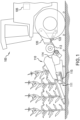
- an exemplary embodiment of an agricultural vehicle 100 is illustrated in the form of a combine harvester that includes a power source 105 in the form of an engine, a header 110 that is configured for harvesting corn or other stalked crops.
- the header 110 is mounted to the vehicle 100 by coupling to a feeder housing 120 and an actuator 122.
- the header 110 includes a header frame 114 carrying a plurality of row units 111 each including a pair of deck plates and a chopper 115, as is known. Crop material, including corn ears and stalks, collected by the header 110 may then be conveyed to the feeder housing 120 by a screw conveyor 113.
- a power take-off 210 that extends through a cowl 121 of the feeder housing 120.
- the power take-off 210 is coupled to the power source 105 (illustrated in FIG. 1 ) by coupling to a transmission coupled to the power source 105.
- the power take-off 210 may include, for example, two or more universal joints ("U-joints") 211 that are connected to one another in order to transmit power to a coupled element. While the power take-off 210 is illustrated and described as a series of coupled together U-joints 211, it should be appreciated that the power take-off 210 can include a plurality of other types of joints or, alternatively, include or consist of a drive shaft.
- the power take-off 210 can couple to a gearbox 220 that is coupled to one or more driven elements of the header 110, such as one of the row units 111 and/or one or more elements of the row units 111 including the chopper 115 and/or a stalk roll, in order to drive the coupled element(s). It should thus be appreciated that the power take-off 210 drives one or more driven elements of the header 110.
- the attachment (agricultural header) 110 provided according to the present disclosure includes a shield assembly 300 that is associated with and covers the power take-off 210 extending through the cowl 121 of the housing (feeder housing) 120.
- the shield assembly 300 includes a rigid section 310 and a flexible section 320 coupled to the rigid section 310.
- the rigid section 310 defines a first diameter D1 and the flexible section 320 defines a second diameter D2 that is greater than the first diameter D2.
- Exemplary values for the first diameter D1 include, but are not limited to, diameters in the range of 220-260 mm, such as 240 mm, and exemplary values for the second diameter D2 include, but are not limited to, diameters in the range of 315-355 mm, such as 335 mm. It should be appreciated that the values for the first diameter D1 and the second diameter D2 may be chosen for a variety of reasons, including but not limited to the available space in the area, the size of the power take-off 210, etc.
- the power take-off 210 extends through the cowl 121 and the shield assembly 300 to drive one or more elements of the header 110.
- the header 110 is movable with respect to the feeder housing 120. Generally, the movement of the header 110 with respect to the feeder housing 120 is tilting, as is known.
- the flexible section 320 of the shield assembly 300 is configured to fit over and maintain overlap with the cowl 121 during tilting of the header 110. The overlap of the flexible section 320 with the cowl 121 is illustrated by the distance O in FIG. 3 , which indicates where the cowl 121 is covered by the flexible section 320.
- the flexible section 320 of the shield assembly 300 can deform and flex in response to tilting of the header 110, which allows the flexible section 320 to remain fitted over and overlapped with the cowl 121 during tilt to cover the power take-off 210.
- the flexible section 320 may comprise a variety of materials, including but not limited to elastomers such as rubber, urethanes, etc. that are capable of elastically deforming without breaking during tilting of the header 110.
- the rigid section 310 may be coupled to a portion of the header 110 where there is little, if any, relative movement so the rigid section 310 does not need to flex (or be flexible) in order to cover the power take-off 210.
- the shield assembly 300 including the flexible section 320 that fits over the cowl 121 allows the header 110 to tilt while still shielding the power take-off 210 during the tilting.
- the flexible section 320 can be configured to maintain various amounts of overlap O with the cowl 121 during different tilting movements of the header 110 relative to the feeder housing 120. In some embodiments, the flexible section 320 is configured to maintain at least 30 mm of overlap O with the cowl 121 during 3° of tilting, such as lateral tilting, of the header 110. As used herein, "lateral" tilting generally refers to tilting of the header 110 that occurs in a width direction of the header 110, i.e., in a direction that extends into the page in FIG. 1 .
- the flexible section 320 may alternatively or additionally be configured to maintain at least 30 mm of overlap O with the cowl 121 during at least 3° of fore-aft, i.e., front-to-back, tilting, such as 8 degrees of aft tilting and 9 degrees of fore tipping.
- tilting such as 8 degrees of aft tilting and 9 degrees of fore tipping.
- the flexible section 320 is configured to maintain at least 50 mm of overlap O with the cowl 121 when there is no tilting of the header 110. It should be appreciated that the flexible section 320 can be configured to maintain other amounts of overlap at different degrees of tilting, or during no tilting, but the previously described values represent exemplary values that may be typical for certain safety standards and/or during normal operation.
- the flexible section 320 defines the second diameter D2 that is greater than the first diameter D1 of the rigid section 310.
- the flexible section 320 having the larger second diameter D2 also helps maintain the overlap O with the cowl 121 during flexing.
- the shield assembly 300 includes one or more ribs 510 that are coupled to the flexible section 320 and space the flexible section 320 from the rigid section 310.
- the rib(s) 510 may, for example, extend radially away from the rigid section 310 to space the flexible section 320 from the rigid section 310. As illustrated, there may be multiple ribs 510 that space the flexible section 320 from the rigid section 310.
- the rib(s) 510 may couple to the flexible section 320 by coupling to a mount 330 that couples the rib(s) 510 to the flexible section 320.
- the mount 330 is a polymer or metal piece that is formed integrally with the rib(s) 510 and the flexible section 320 is mounted to the mount 330 by one or more mounting plates 331 that clamp the flexible section 320 to the mount 330.
- the mounting plate(s) 331 may clamp the flexible section 320 to the mount 330 through compression that is provided by one or more bolts 332 coupling the mounting plate(s) 331 to the mount 330.
- the rigid section 310 and the flexible section 320 may each define a generally oval cross-section.
- the cross-sections are "generally" oval in the sense that the cross-sections may not be fully oval due to, for example, gaps formed in the rigid section 310 and/or the flexible section 320, i.e., the rigid section 310 and/or the flexible section 320 may define, for example, an interrupted oval cross-section that is otherwise oval except for the gap(s).
- the flexible section 320 may have a generally oval shape in the resting/unflexed state but can define other cross-section shapes when deformed during tilting of the header 110.
- the mount 330 and the mounting plate(s) 331 may define a generally oval shape that complements the shape of the flexible section 320.
- the shield assembly 300 may include a slider 340 that slideably couples the flexible section 320 to the rigid section 310.
- the slider 340 includes one or more elongated slots 341 that have a slider bolt 342 disposed therein.
- the slider bolt 342 may be coupled to the rigid section 310 and help to keep the slider 340 and the flexible section 320 coupled to the rigid section 310.
- the rib(s) 510 and the mount 330 couple the flexible section 320 to the slider 340, with the rib(s) 510 coupling the mount 330 to the slider 340.
- the slider 340 may have a shape that complements the rigid section 310 so the slider 340 is capable of smoothly sliding along the rigid section 310 without being too loose.
- a latch 333 coupled to the mount 330 may be used to close the flexible section 320 and cover the power take-off 210.
- the rigid section 310 includes a pair of rigid sections 311A, 311B forming the rigid section 310 and a section latch 312 that can be used to lock and unlock the rigid sections 311A, 311B to one another.
- the rigid section 310 may also include a first latch opening 313 and a second latch opening 314 that is spaced from the first latch opening 313.
- the slider 340 may include a latch 343 that is configured to latch to the first latch opening 313 when the slider 340 is at a first latch position, illustrated in FIG. 6 , and latch to the second latch opening 314 when the slider 340 is at a second position. In the illustrated embodiment of FIG.
- the slider 340 may be in the first position to "close” the shield assembly 300, i.e., cover the power take-off 210, and be in the second position to "open” the shield assembly 300, i.e., expose the power take-off 210.
- a user may unlatch the latch 343 from the respective latch opening 313, 314 before sliding the slider 340 to the desired position and latching the latch 343 to the respective latch opening 313, 314.
- the slider 340 is configured to slide between the first position and the second position along a slider axis SA that is parallel to an axis of rotation AR of the power take-off 210, as best seen in FIG. 6 .
- the slider 340 thus provides an easy and convenient way for a user to both cover and uncover the power take-off 210 with the shield assembly 300 in a manner that does not require any special tools, such as a spanner.
- the shield assembly 300 may include a mounting section 350 at an end of the shield assembly 300 opposite the flexible section 320.
- the mounting section 350 may be flexible or rigid and coupled to the rigid section 310.
- the mounting section 350 may include an end surface 351 that covers a part of the opening through the rigid section 310.
- the end surface 351 has a take-off opening 352 formed therein that allows the power take-off 210 to extend therethrough.
- the end surface 351 may also include a plurality of mounting features 353, 354, illustrated as protrusions 353 and openings 354, that can couple to corresponding features of the header 110 to secure the shield assembly 300.
- the illustrated mounting section 350 is exemplary only and the shield assembly 300 may be mounted in the header 110 in any suitable fashion according to the present disclosure.
- the shield assembly 300 provided according to the present disclosure can fit over and maintain overlap O with the cowl 121 during tilting of the attachment (header) 110. Maintaining the overlap O with the cowl 121 allows the shield assembly 300 to continue shielding the power take-off 210 and reduce the risk of damage to the power take-off 210 and/or injury to a user.
- the flexible section 320 can have a larger clearance, relative to the cowl 121, than known shield assemblies to allow additional tilting without affecting the function of the shield assembly 300. Even further, the shield assembly 300 can be easily adjustable by incorporating the slider 340 so a user can open and close the shield assembly 300 in a convenient manner that does not require any special tools.
Landscapes
- Engineering & Computer Science (AREA)
- Life Sciences & Earth Sciences (AREA)
- Environmental Sciences (AREA)
- Mechanical Engineering (AREA)
- General Engineering & Computer Science (AREA)
- Soil Sciences (AREA)
- Chemical & Material Sciences (AREA)
- Combustion & Propulsion (AREA)
- Transportation (AREA)
- Arrangement Or Mounting Of Propulsion Units For Vehicles (AREA)
Abstract
A work vehicle includes: a chassis; a housing carried by the chassis and including a cowl (121); a power take-off (210) extending through the cowl (121) and configured to connect to a power source (105); and an attachment movably coupled to the housing and including: at least one driven element coupled to the power take-off (210); and a shield assembly (300) associated with and covering the power take-off (210). The shield assembly (300) includes a rigid section (310) defining a first diameter (D1) and a flexible section (320) coupled to the rigid section (310) and defining a second diameter (D2) that is greater than the first diameter (D1). The flexible section (320) is configured to fit over and maintain overlap with the cowl (121) during tilting of the attachment.
Description
- The present invention pertains to work vehicles and, more specifically, to shields for work vehicles.
- Many work vehicles are known. One type of known work vehicle is an agricultural harvester that is used to harvest crops. An agricultural harvester known as a "combine" is historically termed such because it combines multiple harvesting functions with a single harvesting unit, such as picking, threshing, separating, and cleaning. A combine includes a header which removes the crop, such as corn, from a field, and a feeder housing which transports the crop matter into a threshing rotor. The threshing rotor rotates within a perforated housing, which may be in the form of adjustable concaves, and performs a threshing operation on the crop to remove the grain. Once the grain is threshed it falls through perforations in the concaves onto a grain pan. From the grain pan the grain is cleaned using a cleaning system, and is then transported to a grain tank onboard the combine. A cleaning fan blows air through the sieves to discharge chaff and other debris toward the rear of the combine. Non-grain crop material such as straw from the threshing section proceeds through a residue handling system, which may utilize a straw chopper to process the non-grain material and direct it out the rear of the combine. When the grain tank becomes full, the combine is positioned adjacent a vehicle into which the grain is to be unloaded, such as a semi-trailer, gravity box, straight truck, or the like, and an unloading system on the combine is actuated to transfer the grain into the vehicle.
- Many work vehicles, including agricultural harvesters, include driven elements that are powered by a power take-off. The power take-off couples to a power source, such as an engine or transmission, and couples to the driven element directly or via one or more intermediary couplings. Power take-offs thus allow driven elements to be powered by a power source that is remote from the driven element.
- Since the power take-off must be in motion to transfer power, the power take-off is generally shielded to prevent injury to users and also limit damage to the power take-off. Some power take-offs may span across multiple elements. For example, a power take-off that powers elements of a header, such as the cutter bar, may extend through the feeder housing. Such power take-offs are difficult to shield because the header may be moveable with respect to the feeder housing.
- What is needed in the art is a way to shield a power take-off in areas where the power take-off spans multiple elements.
- Exemplary embodiments provided according to the present disclosure provide a shield assembly with a flexible section that fits over and maintains overlap with a cowl of a housing during tilting of an attachment relative to the housing.
- In some exemplary embodiments provided according to the present disclosure, a work vehicle includes: a chassis; a housing carried by the chassis and including a cowl; a power take-off extending through the cowl and configured to connect to a power source; and an attachment movably coupled to the housing and including: at least one driven element coupled to the power take-off; and a shield assembly associated with and covering the power take-off. The shield assembly includes a rigid section defining a first diameter and a flexible section coupled to the rigid section and defining a second diameter that is greater than the first diameter. The flexible section is configured to fit over and maintain overlap with the cowl during tilting of the attachment.
- One possible advantage that may be realized by exemplary embodiments provided according to the present disclosure is that the flexible section allows tilting of the attachment relative to the housing while maintaining overlap, which may be necessary to meet safety requirements.
- Another possible advantage that may be realized by exemplary embodiments provided according to the present disclosure is that that the flexible section can be easily and conveniently slidable to different positions to access or shield the power take-off.
- For the purpose of illustration, there are shown in the drawings certain embodiments of the present invention. It should be understood, however, that the invention is not limited to the precise arrangements, dimensions, and instruments shown. Like numerals indicate like elements throughout the drawings. In the drawings:
-
FIG. 1 illustrates a side view of an exemplary embodiment of a work vehicle in the form of an agricultural harvester that is provided in accordance with the present disclosure; -
FIG. 2 illustrates an exposed power take-off extending through a housing of the work vehicle ofFIG. 1 ; -
FIG. 3 illustrates an exemplary embodiment of a shield assembly provided according to the present disclosure covering the power take-off ofFIG. 2 ; -
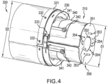
FIG. 4 illustrates a perspective view of the shield assembly ofFIG. 3 by itself; -
FIG. 5 illustrates a perspective view of the shield assembly ofFIGS. 3-4 with a flexible section of the shield assembly removed; -
FIG. 6 illustrates a perspective view of the shield assembly ofFIGS. 3-5 with a slider including a latch to open and close the shield assembly; and -
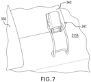
FIG. 7 illustrates a close-up perspective view of the latch ofFIG. 6 . - Referring now to
FIG. 1 , an exemplary embodiment of anagricultural vehicle 100 is illustrated in the form of a combine harvester that includes apower source 105 in the form of an engine, aheader 110 that is configured for harvesting corn or other stalked crops. Theheader 110 is mounted to thevehicle 100 by coupling to afeeder housing 120 and anactuator 122. Theheader 110 includes aheader frame 114 carrying a plurality ofrow units 111 each including a pair of deck plates and achopper 115, as is known. Crop material, including corn ears and stalks, collected by theheader 110 may then be conveyed to thefeeder housing 120 by ascrew conveyor 113. - Referring now to
FIG. 2 as well, an exemplary embodiment of a power take-off 210 is illustrated that extends through acowl 121 of thefeeder housing 120. The power take-off 210 is coupled to the power source 105 (illustrated inFIG. 1 ) by coupling to a transmission coupled to thepower source 105. The power take-off 210 may include, for example, two or more universal joints ("U-joints") 211 that are connected to one another in order to transmit power to a coupled element. While the power take-off 210 is illustrated and described as a series of coupled together U-joints 211, it should be appreciated that the power take-off 210 can include a plurality of other types of joints or, alternatively, include or consist of a drive shaft. As illustrated, the power take-off 210 can couple to agearbox 220 that is coupled to one or more driven elements of theheader 110, such as one of therow units 111 and/or one or more elements of therow units 111 including thechopper 115 and/or a stalk roll, in order to drive the coupled element(s). It should thus be appreciated that the power take-off 210 drives one or more driven elements of theheader 110. - In known work vehicles, such as combines, some power take-offs may extend between two elements that move relative to one another. In such situations, it is difficult to cover and shield the power take-off due to the relative movement between the elements. Ultimately, the goal of the shield is to cover the power take-off at all times during operation of the work vehicle. Further, there should be some degree of overlap between the shield and the elements to shield the power take-off when there is relative movement in order to enhance safety. Known shield assemblies do not always provide the desired overlap during relative movement.
- To address some of the previously described issues with known work vehicles, and referring now to
FIGS. 3-5 as well, the attachment (agricultural header) 110 provided according to the present disclosure includes ashield assembly 300 that is associated with and covers the power take-off 210 extending through thecowl 121 of the housing (feeder housing) 120. Theshield assembly 300 includes arigid section 310 and aflexible section 320 coupled to therigid section 310. As can be appreciated fromFIG. 4 especially, therigid section 310 defines a first diameter D1 and theflexible section 320 defines a second diameter D2 that is greater than the first diameter D2. Exemplary values for the first diameter D1 include, but are not limited to, diameters in the range of 220-260 mm, such as 240 mm, and exemplary values for the second diameter D2 include, but are not limited to, diameters in the range of 315-355 mm, such as 335 mm. It should be appreciated that the values for the first diameter D1 and the second diameter D2 may be chosen for a variety of reasons, including but not limited to the available space in the area, the size of the power take-off 210, etc. - As can be appreciated from
FIGS. 2-5 , the power take-off 210 extends through thecowl 121 and theshield assembly 300 to drive one or more elements of theheader 110. Theheader 110 is movable with respect to thefeeder housing 120. Generally, the movement of theheader 110 with respect to thefeeder housing 120 is tilting, as is known. Theflexible section 320 of theshield assembly 300 is configured to fit over and maintain overlap with thecowl 121 during tilting of theheader 110. The overlap of theflexible section 320 with thecowl 121 is illustrated by the distance O inFIG. 3 , which indicates where thecowl 121 is covered by theflexible section 320. Unlike known shield assemblies, which are generally formed entirely of rigid materials, theflexible section 320 of theshield assembly 300 can deform and flex in response to tilting of theheader 110, which allows theflexible section 320 to remain fitted over and overlapped with thecowl 121 during tilt to cover the power take-off 210. Theflexible section 320 may comprise a variety of materials, including but not limited to elastomers such as rubber, urethanes, etc. that are capable of elastically deforming without breaking during tilting of theheader 110. In contrast, therigid section 310 may be coupled to a portion of theheader 110 where there is little, if any, relative movement so therigid section 310 does not need to flex (or be flexible) in order to cover the power take-off 210. Theshield assembly 300 including theflexible section 320 that fits over thecowl 121 allows theheader 110 to tilt while still shielding the power take-off 210 during the tilting. - The
flexible section 320 can be configured to maintain various amounts of overlap O with thecowl 121 during different tilting movements of theheader 110 relative to thefeeder housing 120. In some embodiments, theflexible section 320 is configured to maintain at least 30 mm of overlap O with thecowl 121 during 3° of tilting, such as lateral tilting, of theheader 110. As used herein, "lateral" tilting generally refers to tilting of theheader 110 that occurs in a width direction of theheader 110, i.e., in a direction that extends into the page inFIG. 1 . Theflexible section 320 may alternatively or additionally be configured to maintain at least 30 mm of overlap O with thecowl 121 during at least 3° of fore-aft, i.e., front-to-back, tilting, such as 8 degrees of aft tilting and 9 degrees of fore tipping. Many different types of mechanisms for tilting theheader 110 relative to thefeeder housing 120 are known, so discussion of such mechanisms is omitted for brevity. In some embodiments, theflexible section 320 is configured to maintain at least 50 mm of overlap O with thecowl 121 when there is no tilting of theheader 110. It should be appreciated that theflexible section 320 can be configured to maintain other amounts of overlap at different degrees of tilting, or during no tilting, but the previously described values represent exemplary values that may be typical for certain safety standards and/or during normal operation. - As previously described, the
flexible section 320 defines the second diameter D2 that is greater than the first diameter D1 of therigid section 310. Theflexible section 320 having the larger second diameter D2 also helps maintain the overlap O with thecowl 121 during flexing. Referring specifically toFIGS. 4 and5 , it is illustrated that theshield assembly 300 includes one ormore ribs 510 that are coupled to theflexible section 320 and space theflexible section 320 from therigid section 310. The rib(s) 510 may, for example, extend radially away from therigid section 310 to space theflexible section 320 from therigid section 310. As illustrated, there may bemultiple ribs 510 that space theflexible section 320 from therigid section 310. The rib(s) 510 may couple to theflexible section 320 by coupling to amount 330 that couples the rib(s) 510 to theflexible section 320. In some embodiments, themount 330 is a polymer or metal piece that is formed integrally with the rib(s) 510 and theflexible section 320 is mounted to themount 330 by one or more mountingplates 331 that clamp theflexible section 320 to themount 330. The mounting plate(s) 331 may clamp theflexible section 320 to themount 330 through compression that is provided by one ormore bolts 332 coupling the mounting plate(s) 331 to themount 330. - As illustrated in
FIG. 5 , therigid section 310 and theflexible section 320 may each define a generally oval cross-section. As used herein, the cross-sections are "generally" oval in the sense that the cross-sections may not be fully oval due to, for example, gaps formed in therigid section 310 and/or theflexible section 320, i.e., therigid section 310 and/or theflexible section 320 may define, for example, an interrupted oval cross-section that is otherwise oval except for the gap(s). It should be appreciated that theflexible section 320 may have a generally oval shape in the resting/unflexed state but can define other cross-section shapes when deformed during tilting of theheader 110. Similarly, themount 330 and the mounting plate(s) 331 may define a generally oval shape that complements the shape of theflexible section 320. - Referring still to
FIGS. 2-5 , and referring now toFIGS. 6-7 as well, it is illustrated that theshield assembly 300 may include aslider 340 that slideably couples theflexible section 320 to therigid section 310. In some embodiments, theslider 340 includes one or moreelongated slots 341 that have aslider bolt 342 disposed therein. Theslider bolt 342 may be coupled to therigid section 310 and help to keep theslider 340 and theflexible section 320 coupled to therigid section 310. In some embodiments, the rib(s) 510 and themount 330 couple theflexible section 320 to theslider 340, with the rib(s) 510 coupling themount 330 to theslider 340. Theslider 340 may have a shape that complements therigid section 310 so theslider 340 is capable of smoothly sliding along therigid section 310 without being too loose. When theflexible section 320 and therigid section 310 are in the desired position with respect to one another, alatch 333 coupled to themount 330 may be used to close theflexible section 320 and cover the power take-off 210. - Referring specifically to
FIGS. 6-7 , it is illustrated that, in some embodiments, therigid section 310 includes a pair ofrigid sections rigid section 310 and asection latch 312 that can be used to lock and unlock therigid sections rigid section 310 may also include afirst latch opening 313 and a second latch opening 314 that is spaced from thefirst latch opening 313. Theslider 340 may include a latch 343 that is configured to latch to the first latch opening 313 when theslider 340 is at a first latch position, illustrated inFIG. 6 , and latch to the second latch opening 314 when theslider 340 is at a second position. In the illustrated embodiment ofFIG. 6 , theslider 340 may be in the first position to "close" theshield assembly 300, i.e., cover the power take-off 210, and be in the second position to "open" theshield assembly 300, i.e., expose the power take-off 210. To move theslider 340 between the first position and the second position, a user may unlatch the latch 343 from the respective latch opening 313, 314 before sliding theslider 340 to the desired position and latching the latch 343 to the respective latch opening 313, 314. In some embodiments, theslider 340 is configured to slide between the first position and the second position along a slider axis SA that is parallel to an axis of rotation AR of the power take-off 210, as best seen inFIG. 6 . Theslider 340 thus provides an easy and convenient way for a user to both cover and uncover the power take-off 210 with theshield assembly 300 in a manner that does not require any special tools, such as a spanner. - Referring specifically to
FIG. 4 , it is illustrated that theshield assembly 300 may include a mountingsection 350 at an end of theshield assembly 300 opposite theflexible section 320. The mountingsection 350 may be flexible or rigid and coupled to therigid section 310. The mountingsection 350 may include anend surface 351 that covers a part of the opening through therigid section 310. Theend surface 351 has a take-off opening 352 formed therein that allows the power take-off 210 to extend therethrough. Theend surface 351 may also include a plurality of mountingfeatures protrusions 353 andopenings 354, that can couple to corresponding features of theheader 110 to secure theshield assembly 300. It should be appreciated that the illustrated mountingsection 350 is exemplary only and theshield assembly 300 may be mounted in theheader 110 in any suitable fashion according to the present disclosure. - From the foregoing, it should be appreciated that the
shield assembly 300 provided according to the present disclosure can fit over and maintain overlap O with thecowl 121 during tilting of the attachment (header) 110. Maintaining the overlap O with thecowl 121 allows theshield assembly 300 to continue shielding the power take-off 210 and reduce the risk of damage to the power take-off 210 and/or injury to a user. Further, theflexible section 320 can have a larger clearance, relative to thecowl 121, than known shield assemblies to allow additional tilting without affecting the function of theshield assembly 300. Even further, theshield assembly 300 can be easily adjustable by incorporating theslider 340 so a user can open and close theshield assembly 300 in a convenient manner that does not require any special tools. - These and other advantages of the present invention will be apparent to those skilled in the art from the foregoing specification. Accordingly, it is to be recognized by those skilled in the art that changes or modifications may be made to the above-described embodiments without departing from the broad inventive concepts of the invention.
Claims (15)
- A work vehicle, comprising:a chassis;a housing carried by the chassis and comprising a cowl (121);a power take-off (210) extending through the cowl (121) and configured to connect to a power source (105); andan attachment movably coupled to the housing and comprising:at least one driven element coupled to the power take-off (210); anda shield assembly (300) associated with and covering the power take-off (210), the shield assembly (300) comprising:a rigid section (310) defining a first diameter (D1); anda flexible section (320) coupled to the rigid section (310) and defining a second diameter (D2) that is greater than the first diameter (D1), the flexible section (320) being configured to fit over and maintain overlap with the cowl (121) during tilting of the attachment.
- The work vehicle of claim 1, wherein the flexible section (320) is configured to maintain at least 30 mm of overlap with the cowl (121) during 3° of tilting of the attachment.
- The work vehicle of any preceding claim, wherein the flexible section (320) is configured to maintain at least 50 mm of overlap with the cowl (121) when there is no tilting of the attachment.
- The work vehicle of any preceding claim, wherein the flexible section (320) is configured to maintain at least 30 mm of overlap with the cowl (121) during 3° of lateral tilting of the attachment.
- The work vehicle of any preceding claim, wherein the flexible section (320) comprises an elastomer.
- The work vehicle of any preceding claim, wherein the shield assembly (300) comprises at least one rib (510) coupled to the flexible section (320) and spacing the flexible section (320) from the rigid section (310).
- The work vehicle of claim 6, wherein the shield assembly (300) comprises at least one mount coupling (330) the flexible section (320) to the at least one rib (510).
- The work vehicle of claim 6 or 7, wherein the at least one rib (510) extends radially away from the rigid section (310).
- The work vehicle of any preceding claim , wherein the shield assembly (300) comprises a slider (340) that slideably couples the flexible section (320) to the rigid section (310).
- The work vehicle of claim 9, wherein the rigid section (310) comprises a first latch opening (313) and a second latch opening (314) spaced from the first latch opening (313) and the slider (340) comprises a latch (343) configured to latch to the first latch opening (313) when the slider (340) is at a first position and latch to the second latch opening (314) when the slider (340) is at a second position.
- The work vehicle of claim 9, wherein the slider (340) is configured to slide between the first position and the second position along a slider axis (SA) that is parallel to an axis of rotation (AR) of the power take-off (210).
- The work vehicle of any preceding claim, wherein the power take-off (210) comprises at least two universal joints (211) coupled together.
- The work vehicle of any preceding claim, wherein the rigid section (310) and the flexible section (320) each define a generally oval cross-section.
- The work vehicle of any preceding claim, wherein the attachment is an agricultural header (110) and the at least one driven element comprises a row unit (111).
- The work vehicle of claim 14, wherein the housing is a feeder housing (120).
Applications Claiming Priority (1)
| Application Number | Priority Date | Filing Date | Title |
|---|---|---|---|
| US18/081,146 US20240196794A1 (en) | 2022-12-14 | 2022-12-14 | Work vehicle with flexible power take-off shield |
Publications (1)
| Publication Number | Publication Date |
|---|---|
| EP4385299A1 true EP4385299A1 (en) | 2024-06-19 |
Family
ID=89223025
Family Applications (1)
| Application Number | Title | Priority Date | Filing Date |
|---|---|---|---|
| EP23216892.2A Pending EP4385299A1 (en) | 2022-12-14 | 2023-12-14 | Work vehicle with flexible power take-off shield |
Country Status (2)
| Country | Link |
|---|---|
| US (1) | US20240196794A1 (en) |
| EP (1) | EP4385299A1 (en) |
Families Citing this family (2)
| Publication number | Priority date | Publication date | Assignee | Title |
|---|---|---|---|---|
| US11796009B1 (en) * | 2023-01-27 | 2023-10-24 | Ryan D. Hunter | Cover for a universal joint of a driveshaft |
| US12305721B2 (en) * | 2023-01-27 | 2025-05-20 | Ryan D. Hunter | Cover for a universal joint of a driveshaft |
Citations (4)
| Publication number | Priority date | Publication date | Assignee | Title |
|---|---|---|---|---|
| US4157019A (en) * | 1976-09-25 | 1979-06-05 | Jean Walterscheid Gmbh | Releasable coupling device for a power transmission shaft |
| EP0086606A1 (en) * | 1982-02-05 | 1983-08-24 | William Taylor | Safety guard for power-take-off shaft |
| US20120011948A1 (en) * | 2010-07-15 | 2012-01-19 | Harkcom Melanie W | Split spacer ring for removal of cutterbar drive pto |
| EP3088759A2 (en) * | 2015-04-29 | 2016-11-02 | GKN Walterscheid GmbH | Protection device for a drive shaft |
Family Cites Families (24)
| Publication number | Priority date | Publication date | Assignee | Title |
|---|---|---|---|---|
| US3053062A (en) * | 1962-09-11 | Geisthoff | ||
| US2025635A (en) * | 1932-01-15 | 1935-12-24 | Charles C Bishoff | Protector for drive shaft joints |
| US3795118A (en) * | 1972-06-19 | 1974-03-05 | Int Harvester Co | Knuckle shield |
| FR2550833A2 (en) * | 1983-04-27 | 1985-02-22 | Slym | Improvements made to the protection devices covering transmission shafts with a universal joint |
| DE3509127A1 (en) * | 1985-03-14 | 1986-09-25 | Jean Walterscheid Gmbh, 5204 Lohmar | Protective device |
| DE3511578C1 (en) * | 1985-03-29 | 1986-10-09 | Jean Walterscheid Gmbh, 5204 Lohmar | Accident prevention funnel |
| US4605332A (en) * | 1985-04-12 | 1986-08-12 | Weasler Engineering, Inc. | Universal joint guard |
| GB2217670B (en) * | 1988-03-17 | 1991-12-11 | Honda Motor Co Ltd | A method and apparatus for assembling a vehicular driving shaft |
| DE19541511C1 (en) * | 1995-11-08 | 1997-04-24 | Walterscheid Gmbh Gkn | Protective device for cardan shafts with a removable protective funnel |
| IT1283741B1 (en) * | 1996-04-17 | 1998-04-30 | Benzi & Di Terlizzi S R L | PROTECTION DEVICE FOR A TRANSMISSION JOINT IN AGRICULTURAL MACHINES. |
| IT1286699B1 (en) * | 1996-08-14 | 1998-07-15 | Edi Bondioli | A PROTECTIVE COVER WITH COMPONABLE ELEMENTS, FOR THE ACCIDENT PROTECTION OF CARDAN SHAFT TRANSMISSIONS OR |
| US5964076A (en) * | 1997-02-05 | 1999-10-12 | Gehl Company | Mower conditioner gear box steering device |
| DE19829314C1 (en) * | 1998-07-01 | 2000-06-29 | Walterscheid Gmbh Gkn | Protection device for a drive arrangement with a double universal joint |
| NL1012964C2 (en) * | 1999-09-02 | 2001-03-05 | Agritrans Bv | Coupling shaft between a driving machine and a driven machine, provided with a protection. |
| DE10302694A1 (en) * | 2003-01-24 | 2004-07-29 | Maschinenfabrik Kemper Gmbh & Co. Kg | Drive system for harvesting attachment of e.g. corn harvesting machine, has length variable cardan shaft with universal joint at one end connected to drive motor and another joint at another end coupled to harvesting attachment |
| WO2005077140A1 (en) * | 2004-02-17 | 2005-08-25 | Christopher David Lowe | Cover for power take-off |
| US7775891B2 (en) * | 2004-11-19 | 2010-08-17 | Honda Motor Co., Ltd. | Boot for joint |
| JP2006275170A (en) * | 2005-03-29 | 2006-10-12 | Ntn Corp | Fixed type constant velocity universal joint |
| DE102008033920B3 (en) * | 2008-07-18 | 2010-02-04 | Gkn Walterscheid Gmbh | Protection arrangement for a double universal joint |
| ITBO20120193A1 (en) * | 2012-04-12 | 2013-10-13 | Gallignani Spa | SAFETY DEVICE AND PROCEDURE, FOR AGRICULTURAL MACHINES, AND ITS AGRICULTURAL MACHINE. |
| JP6328452B2 (en) * | 2014-03-17 | 2018-05-23 | Ntn株式会社 | Fixed constant velocity universal joint |
| CN106015372A (en) * | 2016-07-20 | 2016-10-12 | 万向钱潮股份有限公司 | Corner limiting structure for novel spherical cage type constant velocity universal joint |
| CA3133937A1 (en) * | 2019-11-07 | 2021-05-14 | Lusetti, Lea | Drive shaft with lubricated accident-prevention end protections |
| WO2021132253A1 (en) * | 2019-12-26 | 2021-07-01 | Ntn株式会社 | Fixed-type constant velocity universal joint |
-
2022
- 2022-12-14 US US18/081,146 patent/US20240196794A1/en active Pending
-
2023
- 2023-12-14 EP EP23216892.2A patent/EP4385299A1/en active Pending
Patent Citations (4)
| Publication number | Priority date | Publication date | Assignee | Title |
|---|---|---|---|---|
| US4157019A (en) * | 1976-09-25 | 1979-06-05 | Jean Walterscheid Gmbh | Releasable coupling device for a power transmission shaft |
| EP0086606A1 (en) * | 1982-02-05 | 1983-08-24 | William Taylor | Safety guard for power-take-off shaft |
| US20120011948A1 (en) * | 2010-07-15 | 2012-01-19 | Harkcom Melanie W | Split spacer ring for removal of cutterbar drive pto |
| EP3088759A2 (en) * | 2015-04-29 | 2016-11-02 | GKN Walterscheid GmbH | Protection device for a drive shaft |
Also Published As
| Publication number | Publication date |
|---|---|
| US20240196794A1 (en) | 2024-06-20 |
Similar Documents
| Publication | Publication Date | Title |
|---|---|---|
| EP4385299A1 (en) | Work vehicle with flexible power take-off shield | |
| EP3440918B1 (en) | Foldable corn head | |
| EP3707987B1 (en) | Sieve for an agricultural harvester with adjustable louvers and associated adjustment assembly | |
| EP1385366B1 (en) | Elevator slats for an agricultural harvesting machine | |
| EP3219195B1 (en) | Agricultural feeder assembly with a shielded sprocket | |
| EP3863395B1 (en) | Adjustable ear dam for a corn header | |
| US11622505B2 (en) | Agricultural header with constant reel to cutter relationship | |
| EP3503706B1 (en) | Agricultural harvester row unit | |
| EP3090614B1 (en) | Driven shaft with rotational kinetic energy dissipation for an agricultural harvester | |
| EP3530103B1 (en) | Drive unit for a down crop attachment on a header | |
| US10694674B2 (en) | Down crop attachment for a header | |
| US12550823B2 (en) | Agricultural header with a draper belt including a seed saver disposed behind one or more crop ramps | |
| US12565914B2 (en) | Power transfer arrangement including coupling clutches for an agricultural vehicle | |
| EP4309485B1 (en) | Integrated step-up within combine hitch | |
| CA3072370C (en) | Agricultural header with constant reel to cutter relationship | |
| WO2023018930A1 (en) | End shield attachment of combine header reel |
Legal Events
| Date | Code | Title | Description |
|---|---|---|---|
| PUAI | Public reference made under article 153(3) epc to a published international application that has entered the european phase |
Free format text: ORIGINAL CODE: 0009012 |
|
| STAA | Information on the status of an ep patent application or granted ep patent |
Free format text: STATUS: THE APPLICATION HAS BEEN PUBLISHED |
|
| AK | Designated contracting states |
Kind code of ref document: A1 Designated state(s): AL AT BE BG CH CY CZ DE DK EE ES FI FR GB GR HR HU IE IS IT LI LT LU LV MC ME MK MT NL NO PL PT RO RS SE SI SK SM TR |
|
| STAA | Information on the status of an ep patent application or granted ep patent |
Free format text: STATUS: REQUEST FOR EXAMINATION WAS MADE |
|
| 17P | Request for examination filed |
Effective date: 20241219 |