EP4385048B1 - Verfahren und maschine zur herstellung von mindestens zwei verschiedenen spulen um ein bauteil eines artikels - Google Patents
Verfahren und maschine zur herstellung von mindestens zwei verschiedenen spulen um ein bauteil eines artikels Download PDFInfo
- Publication number
- EP4385048B1 EP4385048B1 EP22754571.2A EP22754571A EP4385048B1 EP 4385048 B1 EP4385048 B1 EP 4385048B1 EP 22754571 A EP22754571 A EP 22754571A EP 4385048 B1 EP4385048 B1 EP 4385048B1
- Authority
- EP
- European Patent Office
- Prior art keywords
- wire
- winding
- component
- clamp
- station
- Prior art date
- Legal status (The legal status is an assumption and is not a legal conclusion. Google has not performed a legal analysis and makes no representation as to the accuracy of the status listed.)
- Active
Links
Images


Classifications
-
- H—ELECTRICITY
- H01—ELECTRIC ELEMENTS
- H01F—MAGNETS; INDUCTANCES; TRANSFORMERS; SELECTION OF MATERIALS FOR THEIR MAGNETIC PROPERTIES
- H01F41/00—Apparatus or processes specially adapted for manufacturing or assembling magnets, inductances or transformers; Apparatus or processes specially adapted for manufacturing materials characterised by their magnetic properties
- H01F41/02—Apparatus or processes specially adapted for manufacturing or assembling magnets, inductances or transformers; Apparatus or processes specially adapted for manufacturing materials characterised by their magnetic properties for manufacturing cores, coils, or magnets
- H01F41/04—Apparatus or processes specially adapted for manufacturing or assembling magnets, inductances or transformers; Apparatus or processes specially adapted for manufacturing materials characterised by their magnetic properties for manufacturing cores, coils, or magnets for manufacturing coils
- H01F41/06—Coil winding
- H01F41/09—Winding machines having two or more work holders or formers
-
- H—ELECTRICITY
- H01—ELECTRIC ELEMENTS
- H01F—MAGNETS; INDUCTANCES; TRANSFORMERS; SELECTION OF MATERIALS FOR THEIR MAGNETIC PROPERTIES
- H01F41/00—Apparatus or processes specially adapted for manufacturing or assembling magnets, inductances or transformers; Apparatus or processes specially adapted for manufacturing materials characterised by their magnetic properties
- H01F41/02—Apparatus or processes specially adapted for manufacturing or assembling magnets, inductances or transformers; Apparatus or processes specially adapted for manufacturing materials characterised by their magnetic properties for manufacturing cores, coils, or magnets
- H01F41/04—Apparatus or processes specially adapted for manufacturing or assembling magnets, inductances or transformers; Apparatus or processes specially adapted for manufacturing materials characterised by their magnetic properties for manufacturing cores, coils, or magnets for manufacturing coils
- H01F41/06—Coil winding
- H01F41/082—Devices for guiding or positioning the winding material on the former
Definitions
- the invention relates to a method and a machine to manufacture at least two different coils around a component of an article.
- the invention finds advantageous application on the tobacco industry to manufacture an electronic component of a disposable cartridge of an electronic cigarette, to which explicit reference will be made in the description below without because of this losing in generality.
- An electronic cigarette normally comprises a re-usable part, which is used several times and contains, among other things, an electric battery (which provides the power needed for the operation of the electronic cigarette) and an electronic processor, which controls the operation of the electronic cigarette. Furthermore, the electronic cigarette comprises a disposable cartridge (namely to be used one single time and to be then replaced), which is coupled to the re-usable part.
- a disposable cartridge which is provided with a transponder equipped with a memory where the features of the disposable cartridge are stored, in particular the features of the (liquid or solid) active substance that has to heated in order to release the vapours to the inhaled; in this way, the re-usable part of the electronic cigarette can read the features of the disposable cartridge coupled thereto, accordingly adjusting the heating to the features of the disposable cartridge.
- the transponder comprises one single wound antenna (namely, one single coil serving as antenna); however, in some applications, the transponder can comprise a plurality of antennas (namely, a plurality of coils serving as antennas), which have different spatial orientations so as to make sure that the transponder is capable of effectively communicating in all possible positions
- US 4 306 646 A discloses a conveyor apparatus for workpieces which are to undergo processing operations along the path of the apparatus.
- the object of the invention is to provide a method and a machine to manufacture at least two different coils around a component of an article, said method and said machine allowing users to operate at a high operating speed (measured as number of components produced per time unit), ensuring, at the same time, a high productive quality (generally measured as percentage of faulty pieces).
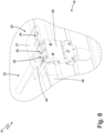
- reference number 1 indicates, as a whole, a component of a disposable cartridge of an electronic cigarette.
- the component 1 approximately has the shape of a parallelepiped having six walls (faces): an upper wall 2, a lower wall 3, which is parallel to and opposite the upper wall 2, a front wall 4, a rear wall 5, which is parallel to an opposite the front wall 4, and two side walls 6 and 7, which are parallel to and opposite one another.
- the component 1 comprises an integrated electronic circuit (not shown), which is arranged inside the component, is generally provided with an electric battery of its own (namely, has a power source of its own) and has six pairs of electrical contacts 8, which are arranged in the area of the walls 4-7: a pair of electrical contacts 8 is arranged in the area of the side wall 6, two pairs of electrical contacts 8 are arranged in the area of the front wall 4, a pair of electrical contacts 8 is arranged in the area of the side wall 7, and two pairs of electrical contacts 8 are arranged in the area of the rear wall 5.
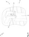
- the component 1 comprises six coils 9-14, which are wound: two coils 9 and 10 with a larger size (area), which surround the walls 4-7 and are arranged at the opposite ends of the component 1 (namely, the coil 9 is arranged close to the upper wall 2, whereas the coil 10 is arranged close to the lower wall 3), two coils 11 and 12 with an intermediate size (area), which surround the walls 2-3 and 6-7 and are arranged at the opposite ends of the component 1 (namely, the coil 11 is arranged close to the front wall 4, whereas the coil 12 is arranged close to the rear wall 5), and two coils 13 and 14 with a smaller size (area), which surround the walls 2-5 and are arranged at the opposite ends of the component 1 (namely, the coil 13 is arranged close to the side wall, 6 whereas the coil 14 is arranged close to the side wall 7).
- Each coil 9-14 is wound and consists of a plurality of turns of an externally insulated conductor wire 15, which form a winding; in the embodiment shown in the accompanying figures there are approximately 10-15 turns.
- Each coil 9-14 (namely, the wound wire 15 making up each coil 9-14) has two ends (obviously, an initial end and a final end depending on the winding direction), which are welded to a corresponding pair of electrical contacts 8.
- the electronic circuit of the component 1 uses the six coils 9-14 in an alternative or simultaneous manner in order communicate, through radio frequency, with other electronic devices arranged nearby.
- the electronic circuit of the component 1 could also use the six coils 9-14 to generate power (used for its own operation and/or to charge its own electric battery) exploiting an electromagnetic field generated by an electronic device arranged nearby; namely, the electronic circuit of the component 1 could also use the six coils 9-14 to carry out an inductive (namely contactless) power charging of its own electric battery.
- the six coils 9-14 of the component 1 constitute corresponding antennas, which can be used to exchange information by means of electromagnetic waves (in this case, the antennas are part of a telecommunication device) and/or can be used to exchange power by means of electromagnetic waves (in this case, the antennas are part of a charging device).
- the component 1 comprises six pairs of pins 16 and 17 (namely, two small columns), which protrude in a projecting manner (namely, perpendicularly) from the corresponding walls 2-7 and are arranged close to corresponding pairs of electrical contacts 8; the two (initial and final) ends of the wound wire 15 making up each coil 9-14 are bent by (circa) 90° around the corresponding pins 16 or 17 before being fitted into the electrical contacts 8 (namely, before reaching the corresponding electrical contacts 8 to which the two ends are welded).
- each coil 9-14 is associated with two respective electrical contacts 8 and two respective pins 16 and 17 and that the pins 16 and 17 are arranged (relatively) close to the electrical contacts 8.
- the component 1 comprises six coils 9-14; according to other embodiments, which are not shown herein, the component 1 has a different number of coils 9-14, which generally ranges from two to five (but, in some cases, there can even be more than six coils 9-14).
- reference number 18 indicates, as a whole, a machine to manufacture the coils 9-14 in the component 1.
- the machine 18 comprises a support body (namely, a frame), which rests on the ground by means of legs and has, at the front, a vertical wall on which the operating members are mounted. Furthermore, the machine 18 comprises a main conveyor 19, which moves the components 1 being processed along a winding path P, which develops between an input station S1 (where the main conveyor 19 receives the components 1 to be provided with the coils 9-14) and an output station S2 (where the main conveyor 19 releases the complete components 1, namely provided with the coils 9-14).
- a support body namely, a frame
- the machine 18 comprises a main conveyor 19, which moves the components 1 being processed along a winding path P, which develops between an input station S1 (where the main conveyor 19 receives the components 1 to be provided with the coils 9-14) and an output station S2 (where the main conveyor 19 releases the complete components 1, namely provided with the coils 9-14).
- the winding path P goes through a series of stations S3-S19 (better described below), where the operations for manufacturing the six coils 9-14 are carried out.
- the main path P comprises one single horizontal and linear segment (namely, substantially developing along a straight line arranged horizontally) arranged between the input station S1 and the output station S2; according to a different embodiment, which is not shown herein, the winding path P comprises: an upper segment, which is horizontal and linear, a lower segment, which is horizontal and linear (and, hence, is parallel to the upper segment), and a semicircular joining segment, which connects the upper segment and the lower segment to one another.
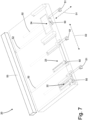
- the main conveyor 19 comprises a plurality of carriages 20, which are moved along the winding path P; as better shown in figures 5 , 6 and 7 , each carriage 20 comprises a support plate 21, in which three different seats 22, 23 and 24 are obtained, each designed to receive and house the same component 1 with different orientations.
- the seat 22 is designed to accommodate the component 1 when the side wall 6 or the side wall 7 of the component 1 rests on the support plate 21
- the seat 23 is designed to accommodate the component 1 when the front wall 4 or the rear wall 5 of the component 1 rests on the support plate 21
- the seat 24 is designed to accommodate the component 1 when the upper wall 2 or the lower wall 3 of the component 1 rests on the support plate 21.
- each support plate 21 is suited to support one single component 1, which can be arranged with three different orientations and in six different positions (each orientation entails two different positions).
- each seat 22, 23 or 24 comprises a clamp 25, which is closed to firmly hold a component 1 resting on the support plate 21 and is opened to release a component 1 resting on the support plate 21.
- Each clamp 25 comprises two opposite jaws 26, which are arranged at the opposite ends of the seat 22, 23 or 24, are movable by means of a linear movement (which develops parallel to the winding path P) and, in use, move between a holding position, in which the two jaws 26 are closer to one another and clamp a component 1 resting on the support plate 21, and a release position, in which the two jaws 26 are farther from one another and release a component 1 resting on the support plate 21.
- the clamps 25 are all controlled together by a same actuator device 27 (namely, all three clamps 25 open and close at the same time), which can be mounted on the support plate 21 or can be on the outside of the support plate 21 and be arranged in a fixed position beside the main conveyor 19.
- each clamp 25 normally is closed, namely, in the absence of an intervention of the actuator device 27, it naturally remains closed; this result is obtained thanks to the presence of a spring, which tends to push the jaws 26 of each clamp 25 towards the closed position and is compressed by the action of the actuator device 27 (namely, the actuator device 27 must overcome the elastic force generated by the spring in order to move the jaws 26 of each clamp 25 towards the open position).
- each clamp 25 has an actuator device 27 of its won, which is separate from and independent of the actuator devices 27 of the other two clamps 25; in this way, each actuator device 27 is optimized for the stroke of the jaws 26 of the corresponding clamp 25.
- the number of seats 22 obtained in the support plate 21 of each carriage 20 could be other than three depending on the number of coils 9-14 to be manufactured and on the conformation of the component 1; hence, the support plate 21 of each carriage 20 could have one single seat 22, 23 or 24 or two seats 22, 23 or 24 or even more than three seats 22, 23 or 24.
- the main conveyor 19 is designed to cyclically move each carriage 20 along the winding path P with an intermittent (step-like) movement, which entails cyclically alternating movement phases, in which the main conveyor 19 moves the carriages 20, and stop phases, in which the main conveyor 19 holds the carriages 20 still.
- the main conveyor 19 comprises an annular guide 28 (namely, closed on itself with a ring shape), which is arranged in a fixed position along the winding path P; in particular, the annular guide 28 consists of one single fixed track (namely, without movement), which is arranged along the winding path P.
- the main conveyor 19 comprises a plurality of slides 29, each supporting a corresponding carriage 20 and being coupled to the guide 28 so as to freely slide along the guide 28.
- the main conveyor 19 comprises a linear electric motor 30, which moves the slides 29 carrying the carriages 20 along the winding path P; furthermore, the linear electric motor 20 comprises an annular stator 31 (namely, a fixed primary element), which is arranged in a fixed position along the guide 28, and a plurality of movable sliders 32 (namely, movable secondary elements), each electrically-magnetically coupled to the stator 31 so as to receive, from the stator 31, a driving force and rigidly connected to a corresponding slide 29.
- an annular stator 31 namely, a fixed primary element
- movable sliders 32 namely, movable secondary elements
- the main conveyor 19 is a conveyor belt and comprises (at least) a flexible belt, which supports the carriages 20 and is closed in a ring shape around at least two end pulleys (at least one of them being motor-driven).
- the main conveyor 19 is a drum (arranged in a vertical horizontal manner), which is mounted so as to rotate around a central rotation axis; obviously, in this embodiment, the winding path P has a circular shape.
- the main conveyor 19 moves the carriage 20 (carrying three seats 22 to be used alternatively) along the winding path P so as to stop one single carriage 20 in the input station S1, in which one single component 1 is placed in the seat 22 of the carriage 20 by laying the side wall 6 on the support plate 21 (namely, with the side wall 7 arranged horizontally and in the highest point).
- a motor-driven arm 33 provided with a holding head 34, which is designed to grab the component 1 holding it on part of the walls 4 and 5 (namely, leaving the side walls 6 and 7 completely free); when the carriage 20 is standing still in the input station S1, the motor-driven arm 33 inserts a component 1 in the seat 22 of the carriage 20 by laying the side wall 6 on the support plate 21.
- the main conveyor 19 moves the carriage 20 (carrying one single component 1 in its own seat 22) along the winding path P and from the input station S1 to the winding station S3, in which the carriage 20 stops and in which a winding unit 35 (which is shown more in detail in figures 9-12 ) winds an externally insulated conductor wire 15 around the component 1 carried by the carriage 20 in order to obtain a series of turns making up the coil 14.
- the main conveyor 19 moves the carriage 20 (carrying one single component 1 in its own seat 22) along the winding path P and from the winding station S3 to the welding station S4 (arranged downstream of the winding station S3), in which the carriage 20 stops and in which the two opposite ends of the coils 14, which was wound in the previous winding station S3, are welded (for example, through ultrasounds, through heat sealing or through laser) to the two corresponding electrical contacts 8 by a welding unit 36 (shown more in detail in figure 13 ).
- the main conveyor 19 moves the carriage 20 (carrying one single component 1 in its own seat 22) along the winding path P and from the welding station S4 to the handling station S5 (arranged downstream of the welding station S4), in which the carriage 20 stops and in which the component 1 is turned upside-down (namely, rotated around itself by 180°) in order to be placed in the seat 22 of the carriage 20 by laying the side wall 7 on the support plate 21 (namely, with the side wall 6 arranged horizontally and in the highest point).
- a motor-driven arm 37 provided with a holding head 38, which is designed to grab the component 1 holding it on part of the walls 4 and 5 (namely, leaving the side walls 6 and 7 completely free); when the carriage 20 is standing still in the handling station S5, the motor-driven arm 37 grabs the component 1 standing in the seat 22 of the carriage 20 and rotates it around itself by 180° so as to lay the side wall 7 on the support plate 21 (the side wall 6, which is opposite the side wall 7, was previously resting on the support plate 21).
- a removal unit 39 which, while the motor-driven arm 37 changes the position of the component 1 on the support plate 21, removes (eliminates) excess parts of the two opposite ends of the coil 14 (cut in the previous welding station S4).
- the main conveyor 19 moves the carriage 20 (carrying one single component 1 in its own seat 22) along the winding path P and from the winding station S6 to the welding station S7 (arranged downstream of the winding station S6), in which the carriage 20 stops and in which the two opposite ends of the coils 13, which was wound in the previous winding station S6, are welded (for example, through ultrasounds, through heat sealing or through laser) to the two corresponding electrical contacts 8 by a welding unit 36 (completely identical to the welding unit 36 present in the welding station S4).
- the handling station S8 there also is a removal unit 39 (completely identical to the removal unit 39 present in the handling station S5), which, while the motor-driven arm 40 changes the position of the component 1 on the support plate 21, removes (eliminates) excess parts of the two opposite ends of the coil 13 (cut in the previous welding station S7).
- the main conveyor 19 moves the carriage 20 (carrying one single component 1 in its own seat 23) along the winding path P and from the handling station S8 to the winding station S9, in which the carriage 20 stops and in which a winding unit 35 (completely identical to the winding unit 35 present in the winding station S3) winds an externally insulated conductor wire 15 around the component 1 carried by the carriage 20 in order to obtain a series of turns making up the coil 12.
- the main conveyor 19 moves the carriage 20 (carrying one single component 1 in its own seat 23) along the winding path P and from the winding station S9 to the welding station S10 (arranged downstream of the winding station S9), in which the carriage 20 stops and in which the two opposite ends of the coils 12, which was wound in the previous winding station S9, are welded (for example, through ultrasounds, through heat sealing or through laser) to the two corresponding electrical contacts 8 by a welding unit 36 (completely identical to the welding unit 36 present in the welding station S4).
- the main conveyor 19 moves the carriage 20 (carrying one single component 1 in its own seat 23) along the winding path P and from the welding station S10 to the handling station S11 (arranged downstream of the welding station S10), in which the carriage 20 stops and in which the component 1 is turned upside-down (namely, rotated around itself by 180°) in order to be placed in the seat 23 of the carriage 20 by laying the rear wall 5 on the support plate 21 (namely, with the front wall 4 arranged horizontally and in the highest point).
- a motor-driven arm 42 provided with a holding head 43, which is designed to grab the component 1 leaving the walls 4 and 5 completely free; when the carriage 20 is standing still in the handling station S11, the motor-driven arm 40 grabs the component 1 standing in the seat 23 of the carriage 20 and rotates it around itself by 180° so as to lay the rear wall 5 on the support plate 21 (the front wall 4, which is opposite the rear wall 5, was previously resting on the support plate 21).
- the handling station S11 there also is a removal unit 39 (completely identical to the removal unit 39 present in the handling station S5), which, while the motor-driven arm 42 changes the position of the component 1 on the support plate 21, removes (eliminates) excess parts of the two opposite ends of the coil 12 (cut in the previous welding station S10).
- the main conveyor 19 moves the carriage 20 (carrying one single component 1 in its own seat 23) along the winding path P and from the handling station 511 to the winding station S12, in which the carriage 20 stops and in which a winding unit 35 (completely identical to the winding unit 35 present in the winding station S3) winds an externally insulated conductor wire 15 around the component 1 carried by the carriage 20 in order to obtain a series of turns making up the coil 11.
- the main conveyor 19 moves the carriage 20 (carrying one single component 1 in its own seat 23) along the winding path P and from the winding station S12 to the welding station S13 (arranged downstream of the winding station S12), in which the carriage 20 stops and in which the two opposite ends of the coils 11, which was wound in the previous winding station S12, are welded (for example, through ultrasounds, through heat sealing or through laser) to the two corresponding electrical contacts 8 by a welding unit 36 (completely identical to the welding unit 36 present in the welding station S4).
- the main conveyor 19 moves the carriage 20 (carrying one single component 1 in its own seat 23) along the winding path P and from the welding station S13 to the handling station S14 (arranged downstream of the welding station S13), in which the carriage 20 stops and in which the component 1 is rotated by 90° in order to be placed in the seat 24 of the carriage 20 by laying the upper wall 2 on the support plate 21 (namely, with the lower wall 3 arranged horizontally and in the highest point).
- a motor-driven arm 44 provided with a holding head 45, which is designed to grab the component 1 leaving the upper wall 2 completely free; when the carriage 20 is standing still in the handling station S 14, the motor-driven arm 44 grabs the component 1 standing in the seat 23 of the carriage 20 and rotates it around itself by 90° so as to lay the upper wall 2 on the support plate 21 and moving the component 1 from the seat 23 to the seat 24 (the component 1 was previously located in the seat 23 and the rear wall 5 was previously resting on the support plate 21).
- the handling station S14 there also is a removal unit 39 (completely identical to the removal unit 39 present in the handling station S5), which, while the motor-driven arm 44 changes the position of the component 1 on the support plate 21, removes (eliminates) excess parts of the two opposite ends of the coil 11 (cut in the previous welding station S13).
- the main conveyor 19 moves the carriage 20 (carrying one single component 1 in its own seat 24) along the winding path P and from the handling station S14 to the winding station S15, in which the carriage 20 stops and in which a winding unit 35 (completely identical to the winding unit 35 present in the winding station S3) winds an externally insulated conductor wire 15 around the component 1 carried by the carriage 20 in order to obtain a series of turns making up the coil 10.
- the main conveyor 19 moves the carriage 20 (carrying one single component 1 in its own seat 24) along the winding path P and from the winding station 515 to the welding station S16 (arranged downstream of the winding station S15), in which the carriage 20 stops and in which the two opposite ends of the coils 10, which was wound in the previous winding station S15, are welded (for example, through ultrasounds, through heat sealing or through laser) to the two corresponding electrical contacts 8 by a welding unit 36 (completely identical to the welding unit 36 present in the welding station S4).
- the main conveyor 19 moves the carriage 20 (carrying one single component 1 in its own seat 24) along the winding path P and from the welding station S16 to the handling station S17 (arranged downstream of the welding station S16), in which the carriage 20 stops and in which the component 1 is turned upside-down (namely, rotated on itself by 180°) in order to be placed in the seat 24 of the carriage 20 by laying the lower wall 3 on the support plate 21 (namely, with the upper wall 2 arranged horizontally and in the highest point).
- a motor-driven arm 46 provided with a holding head 47, which is designed to grab the component 1 leaving the upper wall 2 and the lower wall 3 completely free; when the carriage 20 is standing still in the handling station S 17, the motor-driven arm 46 grabs the component 1 standing in the seat 24 of the carriage 20 and rotates it around itself by 180° so as to lay the lower wall 3 on the support plate 21 (the upper wall 2, which is opposite the lower wall 3, was previously resting on the support plate 21).
- the handling station S17 there also is a removal unit 39 (completely identical to the removal unit 39 present in the handling station S5), which, while the motor-driven arm 46 changes the position of the component 1 on the support plate 21, removes (eliminates) excess parts of the two opposite ends of the coil 10 (cut in the previous welding station S16).
- the main conveyor 19 moves the carriage 20 (carrying one single component 1 in its own seat 24) along the winding path P and from the handling station S17 to the winding station S18, in which the carriage 20 stops and in which a winding unit 35 (completely identical to the winding unit 35 present in the winding station S3) winds an externally insulated conductor wire 15 around the component 1 carried by the carriage 20 in order to obtain a series of turns making up the coil 9.
- the main conveyor 19 moves the carriage 20 (carrying one single component 1 in its own seat 24) along the winding path P and from the winding station S15 to the welding station S19 (arranged downstream of the winding station S18), in which the carriage 20 stops and in which the two opposite ends of the coils 9, which was wound in the previous winding station S 18, are welded (for example, through ultrasounds, through heat sealing or through laser) to the two corresponding electrical contacts 8 by a welding unit 36 (completely identical to the welding unit 36 present in the welding station S4).
- the main conveyor 19 moves the carriage 20 (carrying one single component 1 in its own seat 24) along the winding path P and from the welding station S 19 to the output station S2 (arranged downstream of the welding station S 19), in which the carriage 20 stops and in which the component 1 is retrieved from the seat 24 in order to be directed towards an output of the machine 18.
- the output station S2 there is a motor-driven arm 48 provided with a holding head 49, which is designed to grab the component 1 in order to retrieve the component 1.
- the output station S2 there also is a removal unit 39 (completely identical to the removal unit 39 present in the handling station S5), which, while the motor-driven arm 48 retrieves the component 1, removes (eliminates) excess parts of the two opposite ends of the coil 9 (cut in the previous welding station S19).
- a removal unit 39 completely identical to the removal unit 39 present in the handling station S5
- the motor-driven arm 48 retrieves the component 1, removes (eliminates) excess parts of the two opposite ends of the coil 9 (cut in the previous welding station S19).
- One single winding unit 35 will be described hereinafter, since all six winding units 35 are substantially identical to one another and operate all in the same way.
- each carriage 20 comprises, for each seat 22, 23 or 24, two clamps 50 and 51 (better shown in figure 7 ), which are mounted on the support plate 21 under the seat 22, 23 or 24 and are arranged side by side.
- Each clamp 50 or 51 is designed to hold and lock a corresponding end of the wire 15 to be wound around the respective component 1 and is provided with one single movable jaw, which moves back and forth along a horizontal holding direction D1, which is perpendicular to the winding path P (shown in figure 7 ).
- each clamp 50 or 51 is moved along the holding direction D1 by means of a control rod 52 (shown in figure 7 ), which is arranged through the support plate 21 and comes out from the back of the support plate 21 in order to be pushed by and actuator device 53 (shown in figure 7 ) located in a fixed position (namely, mounted on the frame of the machine 18) in the area of each winding unit 35 (namely, in the area of each winding station S3, S6, S9, S12, S15, S18).
- a control rod 52 shown in figure 7
- actuator device 53 shown in figure 7
- each clamp 50 or 51 normally is closed, namely, in the absence of an intervention of the actuator device 53, it naturally remains closed; this result is obtained thanks to the presence of a spring, which tends to push the movable jaw of each clamp 50 or 51 towards the closed position and is compressed by the action of the actuator device 53 (namely, the actuator device 53 must overcome the elastic force generated by the spring in order to move the movable jaw of each clamp 50 or 51 towards the open position).
- each winding unit 35 there are two clamps 54 and 55, which are mounted (on the frame of the machine 18 and, hence, on the outside of the main conveyor 19, so as not to move together with the carriages 20) under the support plates 21 of the carriages 20 and are arranged next to one another; in particular, the pair of clamps 54 and 55 is vertically aligned with a corresponding pair of clamps 50 and 51 carried by a carriage 20, which stops in the area of the winding unit 35.
- Each clamp 54 or 55 is designed to hold and lock a corresponding end of the wire 15 to be wound around the respective component 1 and is provided with one single movable jaw, which moves back and forth along a horizontal holding direction D2, which is parallel to the winding path P (namely, perpendicular to the holding direction D1 and shown in figure 7 ).
- each clamp 54 or 55 opens and closes by means of a movement developing along the holding direction D2 and, therefore, is parallel to the winding path P.
- the clamps 54 and 55 share a common jaw without movement arranged between the clamps 54 and 55.
- the clamp 54 is used to grab the initial end of the wire 15 at the beginning of the winding of the wire 15 around the component 1 and (immediately) before the initial end of the wire 15 is grabbed by the clamp 50 above; on the other hand, in use, the clamp 55 is used to grab the final end of the wire 15 at the end of the winding of the wire 15 around the component 1 and (immediately) after the final end of the wire 15 is grabbed by the clamp 51 above.
- each clamp 54 or 55 normally is closed, namely, in the absence of an intervention of an actuator device, it naturally remains closed; this result is obtained thanks to the presence of a spring, which tends to push the movable jaw of each clamp 54 or 55 towards the closed position and is compressed by the action of the actuator device (namely, the actuator device must overcome the elastic force generated by the spring in order to move the movable jaw of each clamp 54 or 55 towards the open position).
- a spring which tends to push the movable jaw of each clamp 54 or 55 towards the closed position and is compressed by the action of the actuator device (namely, the actuator device must overcome the elastic force generated by the spring in order to move the movable jaw of each clamp 54 or 55 towards the open position).
- Each winding unit 35 comprises a blade 56, which is mounted (on the frame of the machine 18 and, hence, on the outside of the main conveyor 19 so as not to move together with the carriages 20) under the support plates 21 of the carriages 20 in order to be, in use, between a respective clamp 51 carried by a carriage 20 and a respective clamp 55.
- Each winding unit 35 comprises a movable finger 57, which is used to bring the wire 15 close to the component 1 in order to wind the wire 15 around the component 1 and, hence, move the wire 15 away from the component 1.
- Each movable finger 57 has a tubular shape having a central hole going through the movable finger 57 from side to side and accommodating the wire 15; namely, the wire 15 is inserted into a rear opening of the movable finger 57 and comes out from a front opening of the movable finger 57.
- the wire 15 is progressively unwound from a reel contained in a suitable container, goes through a stretching device provided with at least one movable dandy roller operated by a spring and, then, reaches the movable finger 57; each stretching device is configured to apply an always constant stretch to the wire 15.
- the winding unit 35 comprises a common support body 58 (shown in figure 9 ), on which the movable finger 57 is mounted in order to move the movable finger 57; in particular, the movable finger 57 is mounted on the support body 58 in a rigid manner, namely the movable finger 57 always moves with the support body 58 in an integral manner and never makes any kind of movement relative to the support body 58.
- the support body 58 is moved by one single actuator device 59 (schematically shown in figure 9 ) provided with (at least) an independent electric motor of its own.
- each movable finger 57 is placed with a horizontal orientation when the wire 15 has to be vertically moved in order to go up getting close to the component 1 or in order to go down moving away from the component 1; furthermore, in use, each movable finger 57 is placed with a vertical orientation when the wire 15 has to be horizontally moved in order be wound around the component 1.
- Each winding unit 35 comprises a containing body 60 (better shown in figure 11 ), which, in use, is laid against the pin 16 so as to extend the pin 16 when the wire 15 has to be bent around the pin 16 in order to prevent the wire 15 from accidentally slipping away from the pin 16; namely, shortly before the wire 15 is bent by 90° around the pin 16, the containing body 60 is laid against the pin 16 in order to extend the pin 16, thus preventing the wire 15 from accidentally slipping away from the pin 16.
- a containing body 60 (better shown in figure 11 ), which, in use, is laid against the pin 16 so as to extend the pin 16 when the wire 15 has to be bent around the pin 16 in order to prevent the wire 15 from accidentally slipping away from the pin 16; namely, shortly before the wire 15 is bent by 90° around the pin 16, the containing body 60 is laid against the pin 16 in order to extend the pin 16, thus preventing the wire 15 from accidentally slipping away from the pin 16.
- the pin 16 cannot be too large (due to space problems that are not related to the machine 18) and, at the same time, the movable finger 57 cannot get too close to the component 1 when moving in order to prevent small positioning errors (together with constructive tolerances of the component 1) from causing accidental hits of the movable finger 57 against the component 1.
- Each winding unit 35 comprises a containing body 61 (better shown in figure 11 ), which, in use, is laid against the pin 17 so as to extend the pin 17 when the wire 15 has to be bent around the pin 17 in order to prevent the wire 15 from accidentally slipping away from the pin 17; namely, shortly before the wire 15 is bent by 90° around the pin 17, the containing body 61 is laid against the pin 17 in order to extend the pin 17, thus preventing the wire 15 from accidentally slipping away from the pin 17.
- a containing body 61 (better shown in figure 11 ), which, in use, is laid against the pin 17 so as to extend the pin 17 when the wire 15 has to be bent around the pin 17 in order to prevent the wire 15 from accidentally slipping away from the pin 17; namely, shortly before the wire 15 is bent by 90° around the pin 17, the containing body 61 is laid against the pin 17 in order to extend the pin 17, thus preventing the wire 15 from accidentally slipping away from the pin 17.
- the pin 17 cannot be too large (due to space problems that are not related to the machine 18) and, at the same time, the movable finger 57 cannot get too close to the component 1 when moving in order to prevent small positioning errors (together with constructive tolerances of the component 1) from causing accidental hits of the movable finger 57 against the component 1.
- each winding unit 35 comprises a further movable finger 62 (better shown in figure 11 ), which is arranged under the two clamps 54 and 55 and between the two clamps 54 and 55 (namely, under the common jaw without movement arranged between the clamps 54 and 55) and is vertically moved in order to remove the initial end of the wire 15, which can remain inside the clamp 55 even when the clamp 55 is opened (the initial end of the wire 15 is very light and, hence, it often does not manage to naturally remove itself from the clamp 55 due to gravity); in this way, namely, thanks to the removing action exerted by the movable finger 62, the initial end of the wire 15 is prevented from remaining inside the clamp 55 in an undesired manner, thus breaking due to tearing when the carriage 20 moves at the end of the winding.
- a further movable finger 62 (better shown in figure 11 ), which is arranged under the two clamps 54 and 55 and between the two clamps 54 and 55 (namely, under the common jaw without movement arranged between the clamps 54 and 55) and
- the clamp 55 is opened after the initial end of the wire 15 has been engaged by the clamp 54 in order to begin a new winding and, at this point, the movable finger 62 makes a vertical downward work stroke to remove the initial end of the wire 15 from the clamp 55.
- the winding unit 35 is empty (namely, lacks the component 1 carried by a carriage 20), an initial end of the wire 15 is locked in the clamp 55 and the movable finger 57 (arranged horizontally) is under the clamp 55.
- the initial end of the wire 15 locked in the clamp 55 is the initial end with reference to the new winding that has to be performed around the next component 1 that is about to reach the winding unit 35, while, on the other hand, it was the final end of the wire 15 with reference to the previous winding that was completed around the previous component 1 that was previously located in the winding unit 35.
- an operator manually places the initial end of the wire 15 in the clamp 55.
- the carriage 20 moves the component 1 to the winding unit 35, the clamps 50 and 54 open, the movable finger 57 (still arranged horizontally) vertically moves from the bottom to the top in order to cause the initial end of the wire 15 to go, at first, through the clamp 54 and, subsequently, through the clamp 50 and, finally, the clamps 54 and 50 close in order to lock (in two different points) the initial end of the wire 15; preferably, the sole clamp 54 closes at first, while the clamp 50 is still open and, subsequently, the clamp 50 closes as well.
- the clamp 50 opens and closes by means of a movement along the holding direction D1, which is perpendicular to the winding path P, and, hence, in the closing movement, the clamp 50 moves the wire 15 perpendicular to the winding path P by pulling the wire 15 against the component 1 so that the wire 15 rests on a corresponding electrical contact 8.
- the movable finger 57 rotates by 90° so as to move from a horizontal orientation to a vertical orientation and starts to rotate around the component 1 in order to wind the wire 15 around the component 1.
- the wire 15 vertically going up towards the component 1 is bent by the movable finger 57 around the pin 16, which horizontally projects from the component 1, in order to cause the wire 15 to make a 90° turn, which deflects the wire 15 towards a horizontal orientation.
- the 90° rotation of the movable finger 57 moving from a horizontal orientation to a vertical orientation takes place simultaneously with the bending of the wire 15 around the pin 16.
- the containing body 60 is laid against the pin 16 in order to extend the pin 16 when the wire 15 has to be bent around the pin 16, thus preventing the wire 15 from accidentally slipping away from the pin 16.
- the movable finger 57 makes a series of laps around the component 1 in order to obtain, with the wire 15, a series of (vertically staggered) turns around the component 1.
- the clamp 55 opens and the movable finger 62 makes a vertical downward work stroke to remove the initial end of the wire 15 from the clamp 55.
- the containing body 60 When the winding of the wire 15 around the component 1 is almost complete (namely, before ending the last turn of the winding), the containing body 60 is moved away from the component 1 and (preferably) the clamp 54 is opened to free the initial end of the wire 15 (while the clamp 50 remains closed).
- the movable finger 57 bends the horizontally arranged wire 15 around the pin 17 in order to cause the wire 15 to make a 90° turn, which deflects the wire 15 towards a vertical orientation. Simultaneously with the bending of the wire 15 around the pin 17, the movable finger 57 rotates by 90° in order to move from a vertical orientation to a horizontal orientation. As mentioned above, in this step, the containing body 61 is laid against the pin 17 in order to extend the pin 17 when the wire 15 has to be bent around the pin 17, thus preventing the wire 15 from accidentally slipping away from the pin 17.
- the pin 51 is opened.
- the movable finger 57 by vertically moving the wire 15 from the top to the bottom after having bent the wire 15 around the pin 17, causes the final end of the wire 15 to go through the open clamp 51, which closes immediately after, hence locking the final end of the wire 15; subsequently, the movable finger 57, by vertically moving the wire 15 from the top to the bottom after having bent the wire 15 around the pin 17, causes the final end of the wire 15 to also go through the open clamp 55, which closes immediately after, hence locking the final end of the wire 15.
- the clamp 51 opens and closes by means of a movement along the holding direction D1, which is perpendicular to the winding path P, and, hence, in the closing movement, the clamp 51 moves the wire 15 perpendicular to the winding path P by pulling the wire 15 against the component 1 so that the wire 15 rests on a corresponding electrical contact 8.
- the containing body 61 moves away from the component 1 and the winding manufacturing process ends with the movement of the movable blade 56, which, by moving parallel to the winding path P, cuts the final end of the wire 15 after the final end of the wire 15 has been locked both by the clamp 51 and by the clamp 55 (namely, the movable blade 56 cuts the final end of the wire 15 between the portion locked higher by the clamp 51 and the portion locked lower by the clamp 55).
- the winding of the wire 15 around the component 1 is carried out from the bottom to the top; hence, before starting the winding of the wire 15, the wire 15 vertically going up towards the component 1 is bent around the pin 16 (arranged lower) in order to cause the wire 15 to make a 90° turn, which deflects the wire 15 towards a horizontal orientation; furthermore, after having ended the winding of the wire 15, the horizontally arranged wire 15 is bent around the pin 17 (arranged higher) in order to cause the wire 15 to make a 90° bend, which deflects the wire 15 towards a vertical orientation.
- the winding of the wire 15 around the component 1 is carried out from the top to the bottom; hence, before starting the winding of the wire 15, the wire 15 vertically going up towards the component 1 is bent around the pin 16 (arranged higher) in order to cause the wire 15 to make a 90° turn, which deflects the wire 15 towards a horizontal orientation; furthermore, after having ended the winding of the wire 15, the horizontally arranged wire 15 is bent around the pin 17 (arranged lower) in order to cause the wire 15 to make a 90° bend, which deflects the wire 15 towards a vertical orientation.
- the winding of the wire 15 around the component 1 takes place above a vertical segment of the wire 15 reaching the pin 16 (arranged higher) and, hence, helps lock the initial end of the wire 15 against the component 1, ensuring a greater stability of the winding.
- the welding station S4 comprises a corresponding welding unit 36, which is arranged in a fixed position (namely, does not move together with the main conveyor 19) and is provided with a movable welding head 63 to get close to the component 1 carried by a carriage 20 standing still in the welding station S4 so as to weld the two ends of the wire 15 to the corresponding electrical contacts 8 and, subsequently, move away from the component 1 carried by the carriage 20 once the welding has ended.
- the movement of the welding head 63 always is linear and can be oriented vertically (which is the case in the welding stations S4, S7, S10 and S13) or can be oriented horizontally (which is the case in the welding stations S16 and S19) depending on the orientation assumed by the component 1.
- the welding head 63 is provided with two welding elements next to one another to simultaneously weld both ends of the wire 15 to the corresponding electrical contacts 8.
- the welding head 63 is also configured to cut the two ends of the wire 15 downstream of the welds to the two electrical contacts 8, so as to separate the excess part of the two opposite ends of the coil 9-14; namely, the welding head 63 is also provided with blades, which cut the wire 15 downstream of the welds to the two electrical contacts 8.
- the corresponding six welding units 36 are substantially identical to one another and the only significant change lies in the vertical orientation of the welding heads 63 in the welding stations S4, S7, S10 and S13 and in the horizontal orientation of the welding heads 63 in the welding stations S16 and S19 to adjust to the different orientations of the components 1.
- the handling station S5 comprises a corresponding removal unit 39 provided with a blower device 64, which is connected to a common compressed air distributor and is configured to generate a compressed air blow, which is directed from the top to the bottom and hits a corresponding component 1 carried by a carriage 20 standing still in the removal station S5.
- the compressed air blow hits from the top to the bottom a corresponding component 1 carried by a carriage 20 standing still in the removal station S5 and, then, pushes downwards the excess parts of the two opposite ends of the coil 9-14 (cut in the previous welding station S4); preferably, the excess parts of the two opposite ends of the coil 9-14 pushed downwards by a compressed air blow are collected in a container 65 located under the carriage 20.
- the removal unit 39 also comprises a clamp 66, which is arranged in a fixed position (namely, on the outside of the main conveyor 19) under the support plate 21 of a carriage 20 standing still and grabs the excess parts of the two opposite ends of the coil 9-14 while waiting for the excess parts to be directed into the container 65 by the air blows.
- the corresponding six removal units 39 are substantially identical to one another.
- each component 1 is rotated by 90° or 180° around a horizontal rotation axis; according to other embodiments, in one or more handling stations S5, S8, S11, S14, S17 and S19, each component 1 is rotated around several different rotation axes: for example, each component 1 is rotated at first by 90° or 180° (or even by a different angle, such as 45°, 75° or others) around a horizontal rotation axis and then is rotated by 90° or 180° (or even by a different angle, such as 45°, 75° or others) around a vertical rotation axis.
- the component 1 is part of a disposable cartridge of an electronic cigarette, but the method to manufacture coils 9-14 described above can also be applied to the production of components for articles of any type (namely, of any product class).
- the method to manufacture coils 9-14 described above can be applied to the production of components for a machine, a plant, a construction, for example, but not exclusively, of the tobacco, pharmaceutical, food-related or entertainment industry; more in general, the method to manufacture coils 9-14 described above can be applied to the production of components for applications of any type.
- the method to manufacture coils 9-14 described above have numerous advantages. First of all, the method to manufacture coils 9-14 described above allows for an operation at a high operating speed (measured as number of components produced per time unit). Furthermore, the method to manufacture coils 9-14 described above maintains a high productive quality (generally measured as percentage of faulty pieces).
Landscapes
- Engineering & Computer Science (AREA)
- Power Engineering (AREA)
- Manufacturing & Machinery (AREA)
- Coil Winding Methods And Apparatuses (AREA)
- Manufacture Of Motors, Generators (AREA)
- Coils Or Transformers For Communication (AREA)
Claims (22)
- Verfahren zum Herstellen von mindestens zwei verschiedenen Spulen (9-14) um eine Komponente (1) eines Artikels; wobei das Verfahren die Schritte umfasst:Bewegen eines Schlittens (20), der mindestens eine Aufnahme (22, 23, 24) trägt, die ausgelegt ist, die Komponente (1) aufzunehmen, mittels eines Hauptförderers (19) und entlang eines Wicklungspfads (P); undPlatzieren der Komponente (1) in der Aufnahme (22, 23, 24) des Schlittens (20) in einer Eingabestation (S1), die entlang des Wicklungspfads (P) angeordnet ist; gekennzeichnet durchWickeln eines ersten äußerlich isolierten Leiterdrahts (15) um die Komponente (1), um eine Reihe von Windungen zu erhalten, die eine erste Spule (9-14) bilden, in einer ersten Wicklungsstation (S3), die entlang des Wicklungspfads (P) stromabwärts der Eingabestation (S1) angeordnet ist; undWickeln eines zweiten äußerlich isolierten Leiterdrahts (15) um die Komponente (1), um eine Reihe von Windungen zu erhalten, die eine zweite Spule (9-14) bilden, in einer zweiten Wicklungsstation (S6), die entlang des Wicklungspfads (P) stromabwärts der ersten Wicklungsstation (S3) angeordnet ist;Ändern der Orientierung der Komponente (1) in Bezug auf den Schlitten (20) in einer ersten Handhabungsstation (S5), die entlang des Wicklungspfads (P) zwischen der ersten Wicklungsstation (S3) und der zweiten Wicklungsstation (S6) angeordnet ist.
- Verfahren nach Anspruch 1, wobei in der ersten Handhabungsstation (S5) die Komponente vorzugsweise um 90° oder 180° gedreht wird.
- Verfahren nach Anspruch 1 oder 2, wobei der Schlitten (20) mindestens zwei verschiedene Aufnahmen (22, 23, 24) nebeneinander aufweist, die jeweils ausgelegt sind, die Komponente (1) mit einer unterschiedlichen Orientierung aufzunehmen.
- Verfahren nach Anspruch 3, wobei in der ersten Handhabungsstation (S5) die Komponente gedreht wird, vorzugsweise um 90° oder 180°, und auch von einer ersten Aufnahme (22, 23, 24) zu einer zweiten Aufnahme (22, 23, 24) bewegt wird.
- Verfahren nach Anspruch 4, wobei in der ersten Handhabungsstation (S5) die Komponente (1) in derselben Aufnahme (22, 23, 24) verbleibt, wenn sie um 180° gedreht wird, und andererseits von der ersten Aufnahme (22, 23, 24) zur zweiten Aufnahme (22, 23, 24) bewegt wird, wenn sie um 90° gedreht wird.
- Verfahren nach einem der Ansprüche 1 bis 5, und umfassend die weiteren Schritte:Ändern der Orientierung der Komponente (1) in Bezug auf den Schlitten (20) in einer oder mehreren zweiten Handhabungsstationen (S8, S11, S14, S17), die entlang des Wicklungspfad (P) stromabwärts der zweiten Wicklungsstation (S6) angeordnet sind; undWickeln eines oder mehrerer dritter äußerlich isolierter Leiterdrähte (15) um die Komponente (1), um eine Reihe von Windungen zu erhalten, die eine oder mehrere dritte Spulen (9-14) bilden, in einer oder mehreren dritten Wicklungsstationen (S9, S12, S15, S18), die entlang des Wicklungspfads (P) stromabwärts entsprechender zweiter Handhabungsstationen (S8, S11, S14, S17) angeordnet sind.
- Verfahren nach einem der Ansprüche 1 bis 5, und umfassend die weiteren Schritte:Schweißen von zwei entgegengesetzten Enden der ersten Spule (9-14) an zwei entsprechende elektrische Kontakte (8) der Komponente (1) in einer ersten Schweißstation (S4), die entlang des Wicklungspfads (P) stromabwärts der ersten Wicklungsstation (S3) angeordnet ist, undSchweißen von zwei entgegengesetzten Enden der zweiten Spule (9-14) an zwei entsprechende elektrische Kontakte (8) der Komponente (1) in einer zweiten Schweißstation (S7), die entlang des Wicklungspfads (P) stromabwärts der zweiten Wicklungsstation (S6) angeordnet ist.
- Verfahren nach einem der Ansprüche 1 bis 7, wobei Wickeln eines Drahts (15) die weiteren Schritte umfasst:Arretieren eines anfänglichen Endes des Drahts (15) mittels einer ersten Klemme (50), bevor begonnen wird, den Draht (15) zu wickeln; undArretieren eines abschließenden Endes des Drahts (15) mittels einer zweiten Klemme (51) an dem Ende des Wickelns des Drahts (15).
- Verfahren nach Anspruch 8, wobei die erste Klemme (50) und die zweite Klemme (51) durch eine Trägerplatte (21) des Schlittens (20), wo die Aufnahmen (22, 23, 24) definiert sind, getragen werden und unter der Aufnahme (22, 23, 24) angeordnet sind.
- Verfahren nach Anspruch 8 oder 9, wobei die erste Klemme (50) und die zweite Klemme (51) sich mittels einer Bewegung, die zum Wicklungspfad (P) senkrecht ist, öffnen und schließen, derart, dass sie durch Schließen verursachen, dass der Draht (15) mit entsprechenden elektrischen Kontakten (8) der Komponente (1) in Kontakt gelangt.
- Verfahren nach Anspruch 8, 9 oder 10, wobei Wickeln des Drahts (15) die weiteren Schritte umfasst:Arretieren, vor dem Arretieren des anfänglichen Endes des Drahts (15) mittels der ersten Klemme (50), des anfänglichen Endes des Drahts (15) auch mittels einer dritten Klemme (54), die in einer festen Position auf der Außenseite des Hauptförderers (19) angeordnet ist und auf die erste Klemme (50) ausgerichtet ist; undArretieren, nachdem das abschließende Ende des Drahts (15) mittels der zweiten Klemme (51) arretiert worden ist, des abschließenden Endes des Drahts (15) auch mittels einer vierten Klemme (55), die neben der dritten Klemme (54) in einer festen Position auf der Außenseite des Hauptförderers (19) angeordnet ist und auf die zweite Klemme (51) ausgerichtet ist.
- Verfahren nach Anspruch 11, wobei die dritte Klemme (54) und die vierte Klemme (55) sich mittels einer Bewegung, die parallel zum Wicklungspfad (P) ist, öffnen und schließen.
- Verfahren nach Anspruch 12, wobei sich die dritte Klemme (54) und die vierte Klemme (55) eine gemeinsame Klaue ohne Bewegung teilen, die zwischen der dritten Klemme (54) und der vierten Klemme (55) angeordnet ist.
- Verfahren nach Anspruch 11, 12 oder 13, wobei Wickeln des Drahts (15) die weiteren Schritte umfasst:Öffnen der vierten Klemme (55), wenn das Wickeln des Drahts (15) um die Komponente (1) begonnen hat; undvertikales nach unten Bewegen eines ersten beweglichen Fingers (62), der unter der dritten Klemme (54) und der vierten Klemme (55) angeordnet ist, um ein anfängliches Ende des Drahts (15) aus der offenen vierten Klemme (55) zu entfernen.
- Verfahren nach einem der Ansprüche 11 bis 14, wobei Wickeln des Drahts (15) den weiteren Schritt des Schneidens des abschließenden Endes des Drahts (15) mittels einer beweglichen Klinge, die vorzugsweise zwischen der zweiten Klemme (51) und der vierten Klemme (55) angeordnet ist, umfasst, nachdem das abschließende Ende des Drahts (15) sowohl durch die zweite Klemme (51) als auch durch die vierte Klemme (55) arretiert worden ist.
- Verfahren nach einem der Ansprüche 1 bis 15, wobei Wickeln eines Drahts (15) den weiteren Schritt des Bewegens des Drahts (15) mittels eines zweiten beweglichen Fingers (57), der mit dem Draht (15) in einer gleitenden Weise in Eingriff ist, umfasst.
- Verfahren nach Anspruch 16, wobei der zweite bewegliche Finger (57) eine Röhrenform aufweist, die ein zentrales Loch aufweist, das durch den zweiten beweglichen Finger (57) von einer Seite zur anderen verläuft und innerhalb davon der Draht (15) angeordnet ist.
- Verfahren nach Anspruch 16 oder 17, wobei Wickeln des Drahts (15) die weiteren Schritte umfasst:Platzieren des zweiten beweglichen Fingers (57) mit einer horizontalen Orientierung, wenn der Draht (15) vertikal bewegt werden muss, um in die Nähe der Komponente (1) gelangend anzusteigen, oder um sich von der Komponente (1) wegbewegend abzusinken; undPlatzieren des zweiten beweglichen Fingers (57) mit einer vertikalen Orientierung, wenn der Draht (15) horizontal bewegt werden muss, um um die Komponente (1) gewickelt zu werden.
- Verfahren nach einem der Ansprüche 1 bis 18, wobei Wickeln eines Drahts (15) die weiteren Schritte umfasst:Biegen, bevor begonnen wird, den Draht (15) zu wickeln, des Drahts (15) vertikal ansteigend zur Komponente (1) um einen ersten Stift (16), der von der Komponente (1) horizontal vorsteht, um zu verursachen, dass der Draht (15) eine Drehung macht, was den Draht (15) zu einer horizontalen Orientierung ablenkt; undBiegen, nachdem Wickeln des Drahts (15) beendet worden ist, des horizontal angeordneten Drahts (15) um einen zweiten Stift (17), der von der Komponente (1) horizontal vorsteht, um zu verursachen, dass der Draht (15) eine Drehung macht, was den Draht (15) zu einer vertikalen Orientierung ablenkt.
- Verfahren nach Anspruch 19, wobei Wickeln des Drahts (15) die Schritte umfasst:Legen eines ersten Aufnahmekörpers (60) gegen den ersten Stift (16), um den ersten Stift (16) zu verlängern, vor Biegen des Drahts (15) um den ersten Stift (16); undLegen eines zweiten Aufnahmekörpers (61) gegen den zweiten Stift (17), um den zweiten Stift (17) zu verlängern, vor Biegen des Drahts (15) um den zweiten Stift (17).
- Verfahren nach einem der Ansprüche 1 bis 20, wobei der Hauptförderer (19) umfasst:eine ringförmige Führung (28);einen Gleiter (29), der mit der Führung (28) gekoppelt ist, um entlang der Führung (28) frei zu gleiten, und den Schlitten (20) trägt; undeinen Linearelektromotor (30), der den Gleiter (29) bewegt und mit einem ringförmigen Stator (31), der in einer festen Position entlang der Führung (28) angeordnet ist, und mit einem beweglichen Schieber (32), der an den Stator (31) elektromagnetisch gekoppelt ist, um von dem Stator (31) eine Antriebskraft aufzunehmen, und mit dem Gleiter (29) starr verbunden ist, versehen ist.
- Maschine (18) zum Herstellen von mindestens zwei verschiedenen Spulen (9-14) um eine Komponente (1) eines Artikels; wobei die Maschine (18) umfasst:einen Hauptförderer (19), der ausgelegt ist, einen Schlitten (20), der mindestens eine Aufnahme (22, 23, 24) trägt, die ausgelegt ist, die Komponente (1) aufzunehmen, entlang eines Wicklungspfads (P) zu bewegen;eine Eingabestation (S1), die entlang des Wicklungspfads (P) angeordnet ist und konfiguriert ist, die Komponente (1) in der Aufnahme (22, 23, 24) des Schlittens (20) zu platzieren; gekennzeichnet durcheine erste Wicklungsstation (S3), die entlang des Wicklungspfads (P) stromabwärts der Eingabestation (S1) angeordnet ist und konfiguriert ist, einen ersten äußerlich isolierten Leiterdraht (15) um die Komponente (1) zu wickeln, um eine Reihe von Windungen zu erhalten, die eine erste Spule (9-14) bilden; undeine zweite Wicklungsstation (S6), die entlang des Wicklungspfads (P) stromabwärts der ersten Wicklungsstation (S3) angeordnet ist und konfiguriert ist, einen zweiten äußerlich isolierten Leiterdraht (15) um die Komponente (1) zu wickeln, um eine Reihe von Windungen zu erhalten, die eine zweite Spule (9-14) bilden; wobeidie Maschine (18) eine erste Handhabungsstation (S5) umfasst, die entlang des Wicklungspfads (P) zwischen der ersten Wicklungsstation (S3) und der zweiten Wicklungsstation (S6) angeordnet ist und konfiguriert ist, die Orientierung der Komponente (1) in Bezug auf den Schlitten (20) zu ändern.
Applications Claiming Priority (2)
| Application Number | Priority Date | Filing Date | Title |
|---|---|---|---|
| IT102021000021725A IT202100021725A1 (it) | 2021-08-11 | 2021-08-11 | Metodo e macchina per realizzare almeno due diverse bobine attorno ad un componente di un articolo |
| PCT/IB2022/057298 WO2023017381A1 (en) | 2021-08-11 | 2022-08-05 | Method and machine to manufacture at least two different coils around a component of an article |
Publications (2)
| Publication Number | Publication Date |
|---|---|
| EP4385048A1 EP4385048A1 (de) | 2024-06-19 |
| EP4385048B1 true EP4385048B1 (de) | 2024-12-11 |
Family
ID=78463798
Family Applications (1)
| Application Number | Title | Priority Date | Filing Date |
|---|---|---|---|
| EP22754571.2A Active EP4385048B1 (de) | 2021-08-11 | 2022-08-05 | Verfahren und maschine zur herstellung von mindestens zwei verschiedenen spulen um ein bauteil eines artikels |
Country Status (7)
| Country | Link |
|---|---|
| US (1) | US20250132091A1 (de) |
| EP (1) | EP4385048B1 (de) |
| KR (1) | KR20240087674A (de) |
| CN (1) | CN118302831A (de) |
| IT (1) | IT202100021725A1 (de) |
| PL (1) | PL4385048T3 (de) |
| WO (1) | WO2023017381A1 (de) |
Families Citing this family (2)
| Publication number | Priority date | Publication date | Assignee | Title |
|---|---|---|---|---|
| IT202300022218A1 (it) * | 2023-10-24 | 2025-04-24 | Gd Spa | Carrello per ricevere e trattenere degli articoli semilavorati durante lo spostamento lungo un percorso di lavorazione fra una pluralita' di stazioni operative di una macchina confezionatrice e stazione operativa per una macchina confezionatrice di articoli |
| CN118382054B (zh) * | 2024-04-17 | 2024-11-26 | 深圳市星特科技有限公司 | 一种铜线音圈全自动双工位绕线顺线设备 |
Family Cites Families (4)
| Publication number | Priority date | Publication date | Assignee | Title |
|---|---|---|---|---|
| CH559418A5 (de) * | 1972-12-21 | 1975-02-28 | Micafil Ag | |
| US4306646A (en) * | 1977-11-15 | 1981-12-22 | Axis S.P.A. | Conveyor apparatus |
| US4982827A (en) * | 1985-04-01 | 1991-01-08 | Globe Products Inc. | Workpiece processing system |
| EP3449553B1 (de) * | 2016-04-27 | 2020-01-22 | SMZ Wickel- und Montagetechnik AG | Wickelmaschine |
-
2021
- 2021-08-11 IT IT102021000021725A patent/IT202100021725A1/it unknown
-
2022
- 2022-08-05 PL PL22754571.2T patent/PL4385048T3/pl unknown
- 2022-08-05 KR KR1020247007945A patent/KR20240087674A/ko active Pending
- 2022-08-05 WO PCT/IB2022/057298 patent/WO2023017381A1/en not_active Ceased
- 2022-08-05 EP EP22754571.2A patent/EP4385048B1/de active Active
- 2022-08-05 US US18/682,269 patent/US20250132091A1/en active Pending
- 2022-08-05 CN CN202280068880.9A patent/CN118302831A/zh active Pending
Also Published As
| Publication number | Publication date |
|---|---|
| IT202100021725A1 (it) | 2023-02-11 |
| PL4385048T3 (pl) | 2025-03-31 |
| WO2023017381A1 (en) | 2023-02-16 |
| US20250132091A1 (en) | 2025-04-24 |
| CN118302831A (zh) | 2024-07-05 |
| EP4385048A1 (de) | 2024-06-19 |
| KR20240087674A (ko) | 2024-06-19 |
Similar Documents
| Publication | Publication Date | Title |
|---|---|---|
| JP6458105B1 (ja) | 回転電機の製造システム | |
| EP4385048B1 (de) | Verfahren und maschine zur herstellung von mindestens zwei verschiedenen spulen um ein bauteil eines artikels | |
| EP2884507B1 (de) | Aufwickelvorrichtung und verfahren zur bindung von drahtmaterial an eine anschlussklemme | |
| EP1518474B1 (de) | Apparat zur Herstellung von Reissverschlüssen | |
| US5263639A (en) | Robotic coil winding system | |
| CN114050047A (zh) | 一种全自动环形骨架式四轴绕线机 | |
| EP4174599A1 (de) | Verfahren und vorrichtung zur durchführung einer inspektion an einer gruppe von gegenständen | |
| EP4174885B1 (de) | Verfahren und maschine zur herstellung einer spule um eine komponente eines artikels | |
| EP4174886B1 (de) | Verfahren und maschine zur herstellung einer spule um eine komponente eines artikels | |
| JP2009261113A (ja) | コイル搬出装置 | |
| US20250149241A1 (en) | Method and machine to manufacture a coil around a component of an article | |
| US7334445B2 (en) | Method for producing an end lug of a spring member formed of a strand of wire, and apparatus for manufacturing same | |
| US2351116A (en) | Article assembly apparatus | |
| JPH0581165B2 (de) | ||
| US12469978B2 (en) | Method and machine to assemble a transponder provided with a helical antenna in a component of an article | |
| CN118894414A (zh) | 一种自动收卷机 | |
| US20230348204A1 (en) | Clamp device and related transfer apparatus | |
| CN117897706A (zh) | 将设置有螺旋天线的应答器组装到物品部件中的方法和机器 | |
| CN117882083A (zh) | 制造围绕物品的部件的线圈的方法和机器 | |
| JPH0324702A (ja) | 空心コイル巻線挿入装置 | |
| JPH11291196A (ja) | 自動チューブ調尺裁断装置 | |
| EP4430737A1 (de) | Übertragungseinheit zur übertragung von leitfähigen elementen und entsprechendes verfahren | |
| IT202100019685A1 (it) | Metodo e macchina per l’assemblaggio in un componente di un articolo di un transponder provvisto di una antenna avvolta |
Legal Events
| Date | Code | Title | Description |
|---|---|---|---|
| STAA | Information on the status of an ep patent application or granted ep patent |
Free format text: STATUS: UNKNOWN |
|
| STAA | Information on the status of an ep patent application or granted ep patent |
Free format text: STATUS: THE INTERNATIONAL PUBLICATION HAS BEEN MADE |
|
| PUAI | Public reference made under article 153(3) epc to a published international application that has entered the european phase |
Free format text: ORIGINAL CODE: 0009012 |
|
| STAA | Information on the status of an ep patent application or granted ep patent |
Free format text: STATUS: REQUEST FOR EXAMINATION WAS MADE |
|
| 17P | Request for examination filed |
Effective date: 20231222 |
|
| AK | Designated contracting states |
Kind code of ref document: A1 Designated state(s): AL AT BE BG CH CY CZ DE DK EE ES FI FR GB GR HR HU IE IS IT LI LT LU LV MC MK MT NL NO PL PT RO RS SE SI SK SM TR |
|
| GRAP | Despatch of communication of intention to grant a patent |
Free format text: ORIGINAL CODE: EPIDOSNIGR1 |
|
| STAA | Information on the status of an ep patent application or granted ep patent |
Free format text: STATUS: GRANT OF PATENT IS INTENDED |
|
| INTG | Intention to grant announced |
Effective date: 20240822 |
|
| GRAS | Grant fee paid |
Free format text: ORIGINAL CODE: EPIDOSNIGR3 |
|
| GRAA | (expected) grant |
Free format text: ORIGINAL CODE: 0009210 |
|
| STAA | Information on the status of an ep patent application or granted ep patent |
Free format text: STATUS: THE PATENT HAS BEEN GRANTED |
|
| P01 | Opt-out of the competence of the unified patent court (upc) registered |
Free format text: CASE NUMBER: APP_55350/2024 Effective date: 20241009 |
|
| DAV | Request for validation of the european patent (deleted) | ||
| DAX | Request for extension of the european patent (deleted) | ||
| AK | Designated contracting states |
Kind code of ref document: B1 Designated state(s): AL AT BE BG CH CY CZ DE DK EE ES FI FR GB GR HR HU IE IS IT LI LT LU LV MC MK MT NL NO PL PT RO RS SE SI SK SM TR |
|
| REG | Reference to a national code |
Ref country code: GB Ref legal event code: FG4D |
|
| REG | Reference to a national code |
Ref country code: CH Ref legal event code: EP |
|
| REG | Reference to a national code |
Ref country code: IE Ref legal event code: FG4D |
|
| REG | Reference to a national code |
Ref country code: DE Ref legal event code: R096 Ref document number: 602022008669 Country of ref document: DE |
|
| REG | Reference to a national code |
Ref country code: NL Ref legal event code: FP |
|
| REG | Reference to a national code |
Ref country code: LT Ref legal event code: MG9D |
|
| PG25 | Lapsed in a contracting state [announced via postgrant information from national office to epo] |
Ref country code: HR Free format text: LAPSE BECAUSE OF FAILURE TO SUBMIT A TRANSLATION OF THE DESCRIPTION OR TO PAY THE FEE WITHIN THE PRESCRIBED TIME-LIMIT Effective date: 20241211 |
|
| PG25 | Lapsed in a contracting state [announced via postgrant information from national office to epo] |
Ref country code: FI Free format text: LAPSE BECAUSE OF FAILURE TO SUBMIT A TRANSLATION OF THE DESCRIPTION OR TO PAY THE FEE WITHIN THE PRESCRIBED TIME-LIMIT Effective date: 20241211 |
|
| PG25 | Lapsed in a contracting state [announced via postgrant information from national office to epo] |
Ref country code: BG Free format text: LAPSE BECAUSE OF FAILURE TO SUBMIT A TRANSLATION OF THE DESCRIPTION OR TO PAY THE FEE WITHIN THE PRESCRIBED TIME-LIMIT Effective date: 20241211 |
|
| PG25 | Lapsed in a contracting state [announced via postgrant information from national office to epo] |
Ref country code: ES Free format text: LAPSE BECAUSE OF FAILURE TO SUBMIT A TRANSLATION OF THE DESCRIPTION OR TO PAY THE FEE WITHIN THE PRESCRIBED TIME-LIMIT Effective date: 20241211 |
|
| PG25 | Lapsed in a contracting state [announced via postgrant information from national office to epo] |
Ref country code: NO Free format text: LAPSE BECAUSE OF FAILURE TO SUBMIT A TRANSLATION OF THE DESCRIPTION OR TO PAY THE FEE WITHIN THE PRESCRIBED TIME-LIMIT Effective date: 20250311 |
|
| PG25 | Lapsed in a contracting state [announced via postgrant information from national office to epo] |
Ref country code: LV Free format text: LAPSE BECAUSE OF FAILURE TO SUBMIT A TRANSLATION OF THE DESCRIPTION OR TO PAY THE FEE WITHIN THE PRESCRIBED TIME-LIMIT Effective date: 20241211 Ref country code: GR Free format text: LAPSE BECAUSE OF FAILURE TO SUBMIT A TRANSLATION OF THE DESCRIPTION OR TO PAY THE FEE WITHIN THE PRESCRIBED TIME-LIMIT Effective date: 20250312 |
|
| PG25 | Lapsed in a contracting state [announced via postgrant information from national office to epo] |
Ref country code: RS Free format text: LAPSE BECAUSE OF FAILURE TO SUBMIT A TRANSLATION OF THE DESCRIPTION OR TO PAY THE FEE WITHIN THE PRESCRIBED TIME-LIMIT Effective date: 20250311 |
|
| REG | Reference to a national code |
Ref country code: AT Ref legal event code: MK05 Ref document number: 1751068 Country of ref document: AT Kind code of ref document: T Effective date: 20241211 |
|
| PG25 | Lapsed in a contracting state [announced via postgrant information from national office to epo] |
Ref country code: SM Free format text: LAPSE BECAUSE OF FAILURE TO SUBMIT A TRANSLATION OF THE DESCRIPTION OR TO PAY THE FEE WITHIN THE PRESCRIBED TIME-LIMIT Effective date: 20241211 |
|
| PG25 | Lapsed in a contracting state [announced via postgrant information from national office to epo] |
Ref country code: IS Free format text: LAPSE BECAUSE OF FAILURE TO SUBMIT A TRANSLATION OF THE DESCRIPTION OR TO PAY THE FEE WITHIN THE PRESCRIBED TIME-LIMIT Effective date: 20250411 |
|
| PG25 | Lapsed in a contracting state [announced via postgrant information from national office to epo] |
Ref country code: PT Free format text: LAPSE BECAUSE OF FAILURE TO SUBMIT A TRANSLATION OF THE DESCRIPTION OR TO PAY THE FEE WITHIN THE PRESCRIBED TIME-LIMIT Effective date: 20250411 |
|
| PG25 | Lapsed in a contracting state [announced via postgrant information from national office to epo] |
Ref country code: EE Free format text: LAPSE BECAUSE OF FAILURE TO SUBMIT A TRANSLATION OF THE DESCRIPTION OR TO PAY THE FEE WITHIN THE PRESCRIBED TIME-LIMIT Effective date: 20241211 |
|
| PG25 | Lapsed in a contracting state [announced via postgrant information from national office to epo] |
Ref country code: AT Free format text: LAPSE BECAUSE OF FAILURE TO SUBMIT A TRANSLATION OF THE DESCRIPTION OR TO PAY THE FEE WITHIN THE PRESCRIBED TIME-LIMIT Effective date: 20241211 Ref country code: RO Free format text: LAPSE BECAUSE OF FAILURE TO SUBMIT A TRANSLATION OF THE DESCRIPTION OR TO PAY THE FEE WITHIN THE PRESCRIBED TIME-LIMIT Effective date: 20241211 |
|
| PG25 | Lapsed in a contracting state [announced via postgrant information from national office to epo] |
Ref country code: SK Free format text: LAPSE BECAUSE OF FAILURE TO SUBMIT A TRANSLATION OF THE DESCRIPTION OR TO PAY THE FEE WITHIN THE PRESCRIBED TIME-LIMIT Effective date: 20241211 |
|
| PG25 | Lapsed in a contracting state [announced via postgrant information from national office to epo] |
Ref country code: CZ Free format text: LAPSE BECAUSE OF FAILURE TO SUBMIT A TRANSLATION OF THE DESCRIPTION OR TO PAY THE FEE WITHIN THE PRESCRIBED TIME-LIMIT Effective date: 20241211 |
|
| PG25 | Lapsed in a contracting state [announced via postgrant information from national office to epo] |
Ref country code: IT Free format text: LAPSE BECAUSE OF FAILURE TO SUBMIT A TRANSLATION OF THE DESCRIPTION OR TO PAY THE FEE WITHIN THE PRESCRIBED TIME-LIMIT Effective date: 20241211 |
|
| PG25 | Lapsed in a contracting state [announced via postgrant information from national office to epo] |
Ref country code: SE Free format text: LAPSE BECAUSE OF FAILURE TO SUBMIT A TRANSLATION OF THE DESCRIPTION OR TO PAY THE FEE WITHIN THE PRESCRIBED TIME-LIMIT Effective date: 20241211 |
|
| REG | Reference to a national code |
Ref country code: DE Ref legal event code: R097 Ref document number: 602022008669 Country of ref document: DE |
|
| PGFP | Annual fee paid to national office [announced via postgrant information from national office to epo] |
Ref country code: NL Payment date: 20250826 Year of fee payment: 4 |
|
| PG25 | Lapsed in a contracting state [announced via postgrant information from national office to epo] |
Ref country code: DK Free format text: LAPSE BECAUSE OF FAILURE TO SUBMIT A TRANSLATION OF THE DESCRIPTION OR TO PAY THE FEE WITHIN THE PRESCRIBED TIME-LIMIT Effective date: 20241211 |
|
| PGFP | Annual fee paid to national office [announced via postgrant information from national office to epo] |
Ref country code: DE Payment date: 20250827 Year of fee payment: 4 |
|
| PGFP | Annual fee paid to national office [announced via postgrant information from national office to epo] |
Ref country code: PL Payment date: 20250718 Year of fee payment: 4 |
|
| PLBE | No opposition filed within time limit |
Free format text: ORIGINAL CODE: 0009261 |
|
| STAA | Information on the status of an ep patent application or granted ep patent |
Free format text: STATUS: NO OPPOSITION FILED WITHIN TIME LIMIT |
|
| PGFP | Annual fee paid to national office [announced via postgrant information from national office to epo] |
Ref country code: CH Payment date: 20250901 Year of fee payment: 4 |
|
| 26N | No opposition filed |
Effective date: 20250912 |