EP4384800B1 - Bilderfassungssystem zur erfassung eines bildes einer flüssigen probe - Google Patents
Bilderfassungssystem zur erfassung eines bildes einer flüssigen probe Download PDFInfo
- Publication number
- EP4384800B1 EP4384800B1 EP22747069.7A EP22747069A EP4384800B1 EP 4384800 B1 EP4384800 B1 EP 4384800B1 EP 22747069 A EP22747069 A EP 22747069A EP 4384800 B1 EP4384800 B1 EP 4384800B1
- Authority
- EP
- European Patent Office
- Prior art keywords
- lid
- image acquisition
- liquid sample
- extension
- well
- Prior art date
- Legal status (The legal status is an assumption and is not a legal conclusion. Google has not performed a legal analysis and makes no representation as to the accuracy of the status listed.)
- Active
Links
Images


Classifications
-
- G—PHYSICS
- G01—MEASURING; TESTING
- G01N—INVESTIGATING OR ANALYSING MATERIALS BY DETERMINING THEIR CHEMICAL OR PHYSICAL PROPERTIES
- G01N21/00—Investigating or analysing materials by the use of optical means, i.e. using sub-millimetre waves, infrared, visible or ultraviolet light
- G01N21/01—Arrangements or apparatus for facilitating the optical investigation
- G01N21/03—Cuvette constructions
- G01N21/0303—Optical path conditioning in cuvettes, e.g. windows; adapted optical elements or systems; path modifying or adjustment
-
- G—PHYSICS
- G01—MEASURING; TESTING
- G01N—INVESTIGATING OR ANALYSING MATERIALS BY DETERMINING THEIR CHEMICAL OR PHYSICAL PROPERTIES
- G01N21/00—Investigating or analysing materials by the use of optical means, i.e. using sub-millimetre waves, infrared, visible or ultraviolet light
- G01N21/01—Arrangements or apparatus for facilitating the optical investigation
- G01N21/03—Cuvette constructions
- G01N21/0332—Cuvette constructions with temperature control
-
- G—PHYSICS
- G01—MEASURING; TESTING
- G01N—INVESTIGATING OR ANALYSING MATERIALS BY DETERMINING THEIR CHEMICAL OR PHYSICAL PROPERTIES
- G01N21/00—Investigating or analysing materials by the use of optical means, i.e. using sub-millimetre waves, infrared, visible or ultraviolet light
- G01N21/17—Systems in which incident light is modified in accordance with the properties of the material investigated
- G01N21/25—Colour; Spectral properties, i.e. comparison of effect of material on the light at two or more different wavelengths or wavelength bands
- G01N21/251—Colorimeters; Construction thereof
- G01N21/253—Colorimeters; Construction thereof for batch operation, i.e. multisample apparatus
-
- G—PHYSICS
- G01—MEASURING; TESTING
- G01N—INVESTIGATING OR ANALYSING MATERIALS BY DETERMINING THEIR CHEMICAL OR PHYSICAL PROPERTIES
- G01N21/00—Investigating or analysing materials by the use of optical means, i.e. using sub-millimetre waves, infrared, visible or ultraviolet light
- G01N21/01—Arrangements or apparatus for facilitating the optical investigation
- G01N21/03—Cuvette constructions
- G01N21/0303—Optical path conditioning in cuvettes, e.g. windows; adapted optical elements or systems; path modifying or adjustment
- G01N2021/0307—Insert part in cell
Definitions
- the invention relates to an image acquisition system for acquiring an image of a liquid sample, comprising a well that stores liquid sample, an image acquisition device for acquiring an image of the liquid sample in the well, a lid device for covering the well wherein the lid device comprises a lid having a lid part and a lid extension that extends from the lid part into the well. Additionally, the invention relates to a method for acquiring an image of a liquid sample. The invention also relates to a use of a lid device for covering a well in an image acquisition system for acquiring an image of a liquid sample.
- the cell line development is a method for selecting protein/antibodies, achieving a high yield of the protein/antibodies, and optimizing the quality thereof.
- the cell line development is on the other hand a very complicated, labour-intensive, and pricey process. Development time for most pharmaceutical factories is half a year.
- a core tool required in the cell line development is a bioreactor for cell incubation.
- the scale is continually expanded to a volume production scale through repeated transferring steps of selecting and scaling-up. Therefore, for different phases and different quantities of cells, bioreactors of different sizes ranging from a bioreactor at a microliter level to a large-scale bioreactor at a volume production level are required.
- An ideal bioreactor generally needs to enable cells to continually grow in a suspension, dynamically monitor biosignals, and perform feedback control on dissolved oxygen content and a pH value. It is difficult to achieve the foregoing functions in a microliter-leveled bioreactor.
- the cell line development is monitored and/or to acquire images of the liquid sample, in which the cells are arranged.
- an image acquisition device for acquiring images of the cell located in a well.
- the image acquisition device In order to process the acquired images and, thus, to monitor the cell line development it is necessary to acquire sharp images. This is often not possible as light that is received by the image acquisition device passes through media, like among others liquid sample and air, with different optical density wherein the depth of at least one of the media is not known.
- the volume of the air portion within the receptacle depends among others on the liquid sample volume located in the receptacle and on the amount of vaporized liquid sample.
- the volume of the air portion in particular, the distance between the lid and the liquid sample in vertical direction.
- the vertical direction is parallel to a gravity direction. Therefore, it is known to determine the volume of air portion and to consider said volume by setting the image acquisition device. After the volume of air portion is determined, the liquid sample volume is also known.
- US 2013/176 556 A1 discloses a lid for multiwell plates, allowing optical measurement of liquid samples within its wells, while mitigating evaporation from said samples.
- a surface element protrudes from the bottom of the lid into the fluid within a well.
- the protruding element may be hollow or solid such that light directed into the element may act to capture or direct the beam while preventing backscatter from reaching one or more detectors.
- the protruding element may direct the beam from the well without requiring the beam to pass through a fluid/air interface.
- the angle and shape of the lid surfaces and/or light absorbing/blocking colorization may be employed to minimize or eliminate back reflection. Evaporation is controlled by physically capping the well with the lid, either sealing against the face at the top of the well or the inside surface of the well.
- US 2005/239 197 A1 discloses a lid element which is placed on cell culture vessels in which cells contained in a liquid medium are accommodated.
- the lid element is intended to allow determination of metabolism activities of cells which are contained in the cell culture vessels, by means of optical measurement methods, which can be carried out with simple handling by means of laboratory personnel.
- Light-guiding elements are provided on the lid element which can be fitted to the cell culture vessel and, when the lid element is fitted, project into the interior of cavities in the cell vessel.
- At least one optically sensitive layer is formed on one end surface and/or on the outer envelope surface of the light-guiding elements, which are preferably optical waveguides in the form of rods, for detection of chemical substance concentrations which change within the cavities.
- EP 3 556 844 A1 discloses a culturing device that includes a microplate including a plurality of vessels, each of the vessels having a bottom surface having light transmittance and having an opening at an upper portion, a lid having light transmittance and covering an upper surface of the microplate, and an intermediate plate having light transmittance and being sandwiched between the lid and the microplate, the intermediate plate having a plurality of convex portions on a surface of the intermediate plate facing the microplate, provided with a plurality of through holes corresponding to the convex portions.
- the plurality of convex portions and the plurality of through holes are disposed so that when the intermediate plate and the microplate are overlapped, each of the plurality of convex portions is inserted into each of the plurality of vessels and each of the plurality of through holes coincides with the opening of each of the plurality of vessels.
- the lid comes into contact with the intermediate plate so as to close the plurality of through holes provided in the intermediate plate.
- WO 2020/047 397 A1 discloses a method for performing measurements wherein the method includes providing relative movement between a receptacle and a cover over a measurement interval comprising multiple non-overlapping time periods. A distance between the receptacle and the cover changes along a first axis over at least a portion of each time period.
- An apparatus for performing measurements includes a receptacle comprising a substrate and a plurality of wells within the substrate, and a cover.
- the cover includes: (1) a device configured to engage with the receptacle, (2) a control subsystem configured to provide relative movement between the receptacle and the cover, and (3) a measurement subsystem.
- the object of the invention is to provide an image acquisition system by means of which the influence of the air portion volume on the image quality is at least reduced.
- an image acquisition system for acquiring an image of a liquid sample comprising
- Another object of the invention is to provide a method for acquiring an image in which the influence of the air portion volume on the image quality is at least reduced.
- the object is solved by a method for acquiring an image of a liquid sample, the method comprising the following steps:
- the invention comprises the advantage that the lid extension is in physical contact with the liquid sample.
- the optical density of an air portion that is arranged between the liquid device and the liquid sample when the image is not acquired does not have any influence on the image acquisition.
- the optical density of the air portion has not to be considered for setting the image acquisition device.
- Another advantage of the invention is that vaporizing of the liquid sample and thus, a change of the air volume portion, does also not have any influence on the image acquisition.
- the liquid sample depends on the usage field of the processing device. If the processing device is used in a bioreactor, the liquid sample comprises a biological particle.
- the biological particle can be a cell or a microbe.
- the liquid sample can contain a liquid and at least one biological particle. The liquid can promote the growth of the biological particles, in particular cells or microbes, arranged in the liquid. If the processing device is used in a chemical reactor, the liquid sample can comprise one or more chemical reagents.
- a well is a receptacle for receiving the liquid sample.
- the well can be part of a well carrier having a plurality of wells.
- the well carrier is often indicated as microtiter plate or multiwell plate.
- the image acquisition system can comprise a camera for acquiring the image. Additionally, the image acquisition system can comprise an evaluation device for evaluating the acquired images.
- the evaluation device can be a processor or can comprise a processor.
- the image acquisition system comprises an illumination device, in particular a light source, for providing the light beam.
- the illumination device improves the image quality of the images acquired by the image acquisition system.
- the image acquisition device and the illumination device can be arranged opposite to each other.
- the image acquisition device and the illumination device can be arranged opposite to each other with respect to the well, in particular with respect to a plane being perpendicular to a central axis of the well.
- the image acquisition device can be arranged above the well and the illumination device can be arranged below the well.
- the illumination device can be arranged above the well and the image acquisition device can be arranged below the well.
- the arrangement above or below the well refer to the central axis of the well in a state when liquid sample is arranged in the well and/or refer to the direction of the gravity field.
- the image acquisition device and the illumination device can be arranged at the same side of the image acquisition system. This means, both the image acquisition device and the illumination device can be arranged above or below the well.
- the image acquisition device can be arranged in a predetermined distance from a well bottom and/or from the part of the lid extension that is in physical contact with the liquid sample. Such arrangement enables that images in good quality can be acquired and the configuration of the image acquisition device is simplified. In particular, it is not necessary anymore to determine the volume of the air portion as it is done in the known embodiments. This is possible as the length of the light path through the different portions, in particular media, of the image acquisition system having different optical density is known. The distance refers to a distance along the central axis of the well.
- the lid part and the lid extension can be formed in one piece.
- the lid extension can be formed by deep drawing the lid, in particular the lid part.
- the lid extension can be created in a simple manner.
- the lid extension extends in a direction towards the well from the lid part.
- the lid device is used to cover the well when the lid device is placed on the well. In particular, the lid device fully covers an insertion opening of the well through which liquid sample is inserted into the well.
- the part of the lid extension can be a bottom part of the lid extension.
- a bottom part of the lid extension is the part of the lid extension that is arranged closest to the well bottom. In particular, the bottom part is arranged closer to a well bottom than the remaining parts of the lid.
- the bottom part can form a closed end of the lid extension. That means, the bottom part does not comprise any holes through which the liquid sample can pass through the lid extension.
- the bottom part can be transparent and/or light transmissive. Thus, the light beam illuminated from the illumination device can easily pass through the bottom part.
- the bottom part can comprise a mirror to reflect light back.
- the image acquisition device and the illumination device are arranged on the same side of the image acquisition system.
- the lid device that means, the lid part and the remaining part of the lid extension can be transparent and/or light transmissive.
- the bottom part and the remaining lid extension can be formed in one piece.
- the bottom part and the lid extension can be formed in two pieces wherein the lid extension can be attached to the bottom part in a releasable manner.
- the connection between the lid extension and the bottom part can be a form-fit or force fit connection.
- the image acquisition system can comprise a plurality of lid devices wherein the lid devices differ in the length of the lid extension from each other.
- length the distance between the lid part and the bottom part of the lid extension in vertical direction is meant.
- the lid device can comprise a plurality of lid extensions.
- the plurality of lid extensions can extend from the, in particular same, lid part.
- the number of lid extensions can correspond with the number of wells.
- a lid extension is assigned to a well.
- such a lid device is suitable if the image acquisition device has a well carrier with a plurality of wells.
- the image acquisition can be configured such that the image acquisition device acquires one or more images of one well. After acquiring the image or images the well carrier and/or the optical image acquiring device and the illumination device can be moved to a position in which one or more images of another well are acquired.
- the image acquisition system can comprise a movement, in particular rotating, device for moving, in particular rotating, the well.
- a movement device for moving, in particular rotating, the well.
- the image acquisition system can comprise a sensor for sensing whether the lid extension, in particular the bottom part, is in physical contact with the liquid sample.
- the sensor can be arranged on the lid extension, in particular on the bottom part. Thus, it can be determined in an easy manner whether the lid extension is in physical contact with the liquid sample. Said information can be used for acquiring the image as is explained below more in detail.
- the sensor can send a sensor signal, in particular an electrical signal, to a control unit of the image acquisition system when the sensor is in contact with the liquid sample.
- the control unit can turn on the illumination device. Additionally, the control unit can act on the image acquisition device to take an image. The image can be taken after the illumination device is turned on for illuminating the liquid sample.
- the lid device comprises a further lid that is connected with the lid so that a space exists between the lid and the further lid.
- the space is configured to receive at least a part of the liquid sample arranged in the well.
- liquid sample can be sucked into the space and dispensed from the space during liquid sample processing.
- the lid corresponds with an upper part of the lid device and the further lid corresponds with a lower part.
- Such a lid device has the advantage that it can be used for image processing as described above and for processing the liquid sample arranged in the well. In particular, it is possible to process the liquid sample by provision of the space into which liquid sample can be sucked in.
- a further advantage of the lid device is that the liquid sample can be processed and afterwards at least one image of the liquid sample can be taken. Thus, it is not necessary to remove the lid device from the well after the liquid sample is processed. Thus, the liquid sample can be automatically monitored. In particular the liquid sample can be monitored when the well is arranged in a reactor, in particular a chemical reactor or a bioreactor.
- the further lid can comprise an extension tube that extends from a further lid part of the further lid.
- the extension tube can surround a part of the lid extension, in particular the bottom part.
- the extension tube surrounds the part of the lid extension in a tangential direction of the lid extension.
- the extension tube can protrude longer to the well, in particular the bottom well, than the lid extension.
- the extension tube can have an open end. That means, the extension tube has an opening through which the liquid sample can insert into the extension tube, in particular in the space of the extension tube.
- the extension tube and the further lid part can be formed in one piece.
- the lid device can comprise a plurality of extension tubes that extend from the further lid part, respectively.
- the plurality of extension tubes can extend from the, in particular same, further lid part.
- the number of extensions tubes can correspond with the number of wells.
- an extension tube is assigned to a well.
- such a lid device is suitable if the image acquisition device has a well carrier with a plurality of wells.
- the image acquisition system can comprise a pressure control device.
- the pressure control device can control the pressure in the space.
- the pressure control device can be fluidically connected with the well, in particular with liquid sample arranged in the well, by means of the space.
- Such an image acquisition system enables that the pressure control device can alternately apply positive or negative pressure on the liquid sample in order to process the liquid sample arranged in the well.
- a negative pressure can be applied such that the liquid sample does not come into contact with the lid extension during processing the liquid sample in the well.
- Processing of liquid sample can comprise the supply or removal of fluid, in particular gas, into the receptacle and/or mixing of the liquid sample being in the receptacle and/or moving of the liquid sample and/or agitation of biological particles of the liquid sample.
- Moving of the liquid sample can be performed in order to apply shear stress to e.g. cells by means of the moved liquid.
- Mixing of the liquid sample is understood as a process in which the components of the liquid sample, in particular the biological particles, are moved relative to each other in such a way that a new arrangement pattern is created.
- the lid device can be used for performing at least one of the aforementioned processing steps.
- the liquid processing can additionally or alternatively comprise a filtration of the liquid sample by means of a filter of the lid device.
- the image acquisition system can comprise a control unit.
- the control unit can ensure that a negative pressure is applied in the space before an image is acquired. By applying negative pressure, it is achieved that the liquid sample raises in the extension tube and comes in physical contact with the lid extension.
- the control unit can set the height of the liquid sample in the extension tube by applying the corresponding negative pressure in the space.
- the control unit can determine a negative pressure that is needed so that the liquid sample comes into contact with the lid extensions, in particular, the bottom part of the lid extension, and acts on the pressure control device to apply said negative pressure in the space.
- Said procedure has the advantage that a liquid droplet condensed on the lid extension is picked up by the liquid sample that comes into contact with the lid extension. That means, it does not have to be waited that the liquid droplet falls into the liquid sample due to gravity force.
- the negative pressure is applied in the space before the image is acquired.
- the control unit can be configured to check whether at least one part of the lid extension is in physical contact with liquid sample, in particular before an image is acquired by means of the image acquisition device.
- the control unit can check whether the sensor measures that the part of the lid extension is in physical contact with liquid sample. If the sensor determines that at least one part of the lid extension is in physical contact with the liquid sample, the control unit acts on the image acquisition device to acquire an image of the liquid sample.
- the control unit can be configured to act on the image acquisition device to acquire an image after or during a movement, in particular rotating, device moves, in particular rotates, the well.
- the control unit can be configured to act on the pressure control device for processing liquid sample in the well.
- the control unit can be configured to act on the image acquisition device to acquire an image after the processing of the liquid sample is finished or during the processing of the liquid sample.
- the image acquisition device can comprise at least one temperature setting device.
- the image acquisition system can comprise a first temperature setting device for heating or cooling the lid part.
- the first temperature setting device can comprise at least one through hole. Said through hole is positioned such that the lid extension, in particular the bottom part of the lid extension is not covered by the first temperature setting device. Thus, the light illuminated from the illumination device is not blocked by the first setting temperature. Additionally, the bottom part of the lid extension is heated slower than the remaining part of the lid.
- the temperature setting device can be any device by means of which the temperature of the lid extension and/or the temperature of the vaporized liquid of the liquid sample can directly or indirectly be controlled. Said device is used to ensure that the temperature of the lid extension differs from the temperature of the vaporized liquid of the liquid sample.
- the temperature difference between the temperature of the lid extension and the temperature of the vaporized liquid of the liquid sample can be set to a predetermined value by means of the at least one temperature setting device. Alternatively, the temperature difference is not set to a predetermined value.
- the image acquisition system can comprise a second temperature setting device for heating or cooling the well.
- the second temperature changing device heats or cools the liquid sample and/or the vaporized liquid of the liquid sample.
- the first temperature changing device and the second temperature changing device can be arranged opposite each other with respect to the well. This enables a compact structured processing system.
- the well can be, in particular directly, arranged on the second temperature setting device.
- the well can be formed that it covers the second temperature changing device.
- the second temperature setting device can be a heating plate.
- the temperature of the heating plate can be controlled by the control unit.
- the second temperature setting device can have a through hole so that the image acquisition device can receive the light beam.
- the at least one control unit can control the first temperature setting device such that the temperature of the lid part and/or further lid part increases or decreases, in particular by 30 to 60 degree Celsius.
- the temperature of the further lid part can be changed by the first temperature changing device because the lid part is connected with the further lid part as mentioned above.
- the connection can be made such that thermal energy can be conducted between the lid part and the further lid part. If the control unit increases the temperature of the lid part, the temperature of the remaining part of the lid part and the further lid part is higher than the temperature of the lid extension.
- the vaporized liquid of the liquid sample is heated by at least the further lid part, in particular the extension tube, so that the temperature difference between the vaporized liquid of the liquid sample and the lid extension increases.
- the temperature of the lid extension corresponds to the ambient temperature, in particular at least at the begin of operation when the first temperature setting device and/or the second temperature setting device start to heat the lid part and/or the well.
- the lid extension surface on which the vaporized liquid is condensed is arranged in the surface surrounded by the extension tube.
- the at least one control unit can control the second temperature setting device such that the temperature of vaporized liquid of the liquid sample increases, in particular by 30 to 60 degree Celsius.
- the lid extension can remain at e.g. the ambient temperature so that the temperature difference between the lid extension and the vaporized liquid sample increases.
- a lid device for covering a well is used in an image acquisition system for acquiring an image of a liquid sample
- the lid device comprises a lid having a lid part and a lid extension that extends from the lid part into the well and the lid device comprises a further lid that is connected with the lid such that a space exists between the lid and the further lid, wherein at least one part of the lid extension is in physical contact with the liquid sample when an image is acquired by means of an image acquisition device and the part of the lid extension that is in physical contact with the liquid sample is arranged such that light, in particular a light beam, passes through the part of the lid extension before it is received by the image acquisition device.
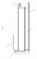
- Figure 1 shows an image acquisition system 1 according to a first embodiment that is used for acquiring an image of a liquid sample 2.
- the liquid sample 2 is stored in a well 3 of the image acquisition system 1.
- Figure 1 shows merely one well 2.
- the image acquisition system 1 can comprise a well carrier 23 that comprises several wells 3 as is shown in fig. 8 .
- the image acquisition system 1 comprises an image acquisition device 4 for acquiring an image of the liquid sample 2 in the well 3.
- the image acquisition device can comprise a camera or be a camera.
- the camera comprises an objective.
- the image acquisition system 1 comprises a lid device 5 for covering the well 3 wherein the lid device 5 comprises a lid 6 having a lid part 7 and a lid extension 8 that extends from the lid part 7 into the well 3.
- the lid extension 8 is in physical contact with the liquid sample 2 when an image is acquired by means of the image acquisition device 4.
- the image acquisition system 1 comprises an illumination device 9 for illuminating a light beam 24.
- the illumination device 9 and the image acquisition device 4 are arranged opposite to each other with respect to the well 3.
- the image acquisition device 4 is arranged below the well 3 and the illumination device 9 is arranged above the well 3.
- the image acquisition device 4 can be arranged above the well 3 and the illumination device 9 can be arranged below the well 3.
- the terms "above” and “below” refer to a gravitation field.
- the part of the lid extension 8 is formed such that a light beam 24 illuminated by the illumination device 9 passes through it before it is received by the image acquisition device 4. That means, the part of the lid extension 8 is arranged between the illumination device 9 and the image acquisition device 4.
- the part of the lid extension 8 is a bottom part 11 of the lid extension 8. Said bottom part 11 is arranged nearest to a well bottom 10.
- the lid extension 8 extends into the well 3. That means, the lid extension 8 is arranged in an inner space 25 surrounded by the well 3 in its circumferential direction.
- the lid device 5 comprises a further lid 13 that is fixedly connected with the lid 6 wherein the further lid 13 and the lid 6 delimit a space 14 between them.
- the further lid 13 comprises a further lid part 16 and an extension tube 15 extending from the further lid part 16.
- the extension tube 15 comprises an open end so that liquid sample can enter into the space 14 when the lid device 5 is arranged on the well 3.
- negative pressure is applied on the space 14 so that the liquid sample 2 is suctioned into the space 14 such that liquid sample 2 gets into physical contact with the bottom part 11 of the lid extension 8.
- the extension tube 14, in particular its opening through which liquid sample 2 enters the space 14, is closer to the well bottom 10 than the bottom part 11 of the lid extension 8.
- the extension tube 15 surrounds at least one part of the lid extension 8, in particular the bottom part 11 in the circumferential direction of the lid extension 8.
- a part of the lid extension 8, in particular the bottom part 11, is arranged in the extension tube 14.
- a sensor 12 is attached to the bottom part 11. The sensor 12 detects if the liquid sample 2 is in contact with the bottom part 11.
- Fig. 2 shows a side view of an image acquisition system 1 according to a second embodiment being not part of the invention.
- the image acquisition system 1 according to the second embodiment differs from the image acquisition system 1 according to the first embodiment in the structure of the lid device 1.
- the lid device 5 merely comprises the lid 6 with the lid part 7 and the lid extension 8. That means, the lid device 5 of the image acquisition system 1 according to the second embodiment does not comprise the further lid 13.
- the lid extension 8 extends from the lid part 7 so that it is in physical contact with the liquid sample 2.
- lid extension 8 has a rectangular shape whereas the lid extension 8 shown in fig. 1 has a tapered shape.
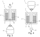
- Fig. 3 shows a side view of an image acquisition system 1 according to a third embodiment being not part of the invention.
- the image acquisition system 1 according to the third embodiment differs from the image acquisition system 1 according to the second embodiment in the length of the lid extension 8.
- the length of the lid extension 8 of the image acquisition system 1 according to the third embodiment is longer than the length of the lid extension 8 of the image acquisition system 1 according to the second embodiment. This means, the lid extension 8 of the image acquisition system 1 according to the third embodiment extends further in the well 3 than the lid extension 8 of the image acquisition system 1 according to the second embodiment and thus is closer to the well bottom 10 than the lid extension 8 according to the second embodiment.
- Fig. 4 shows a side view of an image acquisition system 1 according to a fourth embodiment being not part of the invention.
- the image acquisition system 1 according to the fourth embodiment differs from the image acquisition system 1 according to the third embodiment in the arrangement of the illumination device 9 and the image acquisition device 4.
- the illumination device 9 is arranged below the well 3 and the image acquisition device 4 is arranged above the well 3.
- Fig. 5a-e show processing of the liquid sample 2 and an image taking step with the image acquisition system 1 shown in fig. 1 .
- Fig. 5a shows a state of the image acquisition system 1 in which processing is not started.
- negative pressure is applied in the space 14 as is shown by the arrow. Due to the negative pressure the liquid sample arranged in the extension tube 15 raises. The negative pressure can be set such that the liquid sample does not come into contact with the bottom part 11. This state is shown in fig. 5b .
- a positive pressure is applied to the space 14. Said pressure leads to that the liquid sample is pushed out of the extension tube 8. This state is shown in fig. 5c .
- the aforementioned steps are repeated several times so the liquid sample 2 is processed.
- fig. 5c shows that a liquid sample drop 32 is arranged on the bottom part 11 of the lid extension. This drop results due to condensing of vaporized liquid sample on the bottom part 11.
- Fig. 5d shows a state of the liquid sample 2 in which at least an image shall be taken by the image acquisition system 1.
- a negative pressure is applied on the space 14 so that the liquid sample 2 is suctioned in the space 14.
- the negative pressure is set such that the liquid sample 2 gets into contact with the bottom part 11 of the lid extension 8.
- the sensor 12 detects that the bottom part 11 is in contact with the liquid sample 2.
- a control unit receives a sensor signal and acts on the illumination device 9 to illuminate the light beam 24.
- the light beam 24 passes through an air portion between the illumination device 9 and the bottom part 11, the bottom part 11, the liquid sample 2 and the well bottom 10 before it is received in the image acquisition device 4.
- the image acquisition device 4 can take one or more images of the liquid sample.
- the focal plane of the image acquisition device 4 can be changed so that images in different heights in the well 3 can be acquired.
- positive pressure can be applied in the space 14 so that the state as shown in fig. 5e is achieved.
- ambient pressure can be applied in the space 14 so that the state as shown in fig. 5a is achieved.
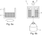
- Fig. 6a-b show processing of the liquid sample 2 and an image taking step with the image acquisition system shown in fig. 3 .
- the liquid sample is processed by rotating the well 3.
- the lid device 5 is attached on the well 3 and one or more images are acquired.
- the well 3 is not rotated when the image is acquired.
- the image acquiring occurs identical to the image acquiring discussed above in fig. 5 .
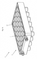
- Fig. 7a-b show processing of the liquid sample and an image taking step with the image acquisition system shown in fig. 2 .
- the lid device 5 is attached on well 3 when the well 3 is rotated as is shown in fig. 7a .
- the well 3 is rotated during the image acquiring as is shown in fig. 7b .
- Fig. 8 a side view of an image acquisition system 1 according to a fifth embodiment and a well carrier 23.
- the well carrier 23 comprises a plurality of wells 3.
- Each of the wells 3 comprises a liquid sample 2.
- Fig. 8 does not show the illumination device 9 and the image acquisition device 4.
- the lid device 5 comprises a lid 6 and further lid 13.
- the further lid part 13 comprises several hollow extension tubes 15 that at partly are arranged in respective wells 3 each of it having a liquid sample 2.
- the extension tubes 15 extend from further lid part 16 towards the well 3.
- the lid device 5 also comprises several lid extensions 8 protruding from the lid part 7.
- the lid extension 8 is partly arranged in the hollow extension tube 15. All lid extensions 8 and extension tubes 15 are identically formed.
- the image acquisition system 1 comprises a first temperature setting device 20 for creating a temperature difference between the temperature of the lid extension 8 and the temperature of a vaporized liquid of the liquid sample 2.
- the lid device 5 comprises a connection part 28 that fluidically connects the space 14 with a pressure control device 18 of the image acquisition system 1.
- the pressure control device 18 is configured to apply a positive or negative pressure. Due to the fluid connection between the space 14 and the pressure control device 18 by means of the connection part 28, the pressure control device 18 applies a positive or negative pressure on the space 14. By applying negative pressure in the space 14 the liquid sample 2 is aspirated into the extension tube 15 and by applying positive pressure in the space 14 the liquid sample 2 arranged in the extension tube 15 is dispensed into the well 3.
- the lid device 5 is placed on the well carrier 23.
- the well carrier 23 comprises a plurality of wells 3 wherein the number of wells 3 corresponds to the number of extension tubes 15.
- the lid extension 8 and the lid part are a one-piece part.
- the lid extension 8 has a rectangular shape wherein only a part of the lid extension 8 is arranged in the well 3.
- the first temperature setting device 20 is, in particular directly, arranged on the lid device 5. As the lid extension 8 extends from the lid part 7 towards the well carrier 23 at least the part of the lid extension 8 being arranged in the well 3 has a different temperature than the lid part 7 when the first temperature setting device 20 heats the lid 6.
- the lid 6 heats gas arranged in the space 14.
- the first temperature setting device 20 can be a heating plate that covers the lid 6.
- the further lid 13 is connected with the lid 6, the further lid 13 is also heated when the lid 6 is heated by the temperature setting device.
- the further lid 13, in particular the extension tube 15 also heats the vaporized liquid of the liquid sample 2 and thus increases the temperature difference between the lid extension 8 and the vaporized liquid of the liquid sample.
- the image acquisition system 1 comprises a second temperature setting device 22.
- the second temperature setting device 22 is used to heat the well carrier 3, in particular the liquid samples 2 arranged in the wells 3.
- the well carrier 3 is arranged on the second temperature setting device 22.
- the well carrier 23 is placed on the second temperature setting device 22.
- the second temperature setting device 22 can be a heating plate.
- the first temperature setting device 20 and the second temperature setting device 22 can be arranged opposite to each other with regard to the well carrier 23.
- the second temperature setting device 22 can heat the well carrier 23 and, thus, the liquid sample 2 and the vaporized liquid sample arranged in the well carrier 23.
- the image acquisition system 1 comprises a control unit 19 for controlling the first temperature setting device 20 and the second temperature setting device 22.
- the first temperature setting device 20 and the second temperature device 22 can be controlled by non-shown different control units 19.
- the control unit 19 can control the first temperature setting device 20 and the second temperature device 22 such that the lid device 5 and/or the well carrier 23 reach a predetermined temperature.
- the lid device 5 comprises non-shown temperature sensors for measuring the temperature of the lid 6 and/or the further lid 13 and/or the well carrier 23 and/or the liquid sample 2.
- the control unit 19 controls the first and/or second temperature setting devices 20, 22 based on the measured temperatures values.
- control unit 19 can control the pressure control device 18.
- the pressure control device 18 can be controlled by a different control unit.
- the control unit is electrically or electronically connected with the first temperature setting device 20 and the second temperature setting device 22. Additionally, the control unit is electrically or electronically connected with the pressure control device 18.
- the electrical connections are shown in dotted lines in fig. 8 whereas the lid extension 8 shown in fig. 8 has a rectangular shape.
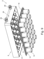
- Fig. 9 shows an explosion view of an image acquisition system according to a sixth embodiment.
- the lid device 5 differs from the lid device 5 shown in fig. 1 in the shape of the lid extension 8.
- the lid extensions 8 have a tapered shape, respectively.
- the lid device 5 comprises a further connection part 29.
- the further connection part 29 is used to fluidically connect the space 14 with a non-shown measurement device.
- the measurement device can be a pressure sensor.
- the pressure sensor measures the pressure within the space 14.
- the measurement device can be a temperature sensor for measuring the temperature of the lid 6.
- the connection part 28 and the further connection part 29 extend from the same lid side 30 in the same direction.
- the lid 6 has a circumferential rim 31.
- the circumferential rim 31 delimits the space 14 in circumferential direction of the lid device 5.
- the circumferential rim 31 extends in the same direction as the lid extension 8.
- the lid extensions 8 are arranged in a matrix structure. That means, there exists several rows and columns each having several lid extensions 8.
- the lid extensions 8 are arranged in distance adjacent to each other.
- the number and arrangement of the extension tubes 15 is identical to the number and arrangement of the lid extensions 8.
- Fig 10 shows a perspective view of the image acquisition system according to the sixth embodiment. Said figure 10 shows that the lid extensions 8 can be formed by deep drawing the lid 6. Thus, there exist recesses 33 in the locations where the lid extensions 8 are arranged.
- Fig. 11 shows a perspective view of image acquisition system 1 and fig. 12 shows a side view of the image acquisition system shown in fig. 11 .
- the first temperature setting device 20 is formed as heating plate and attached to the lid device 5.
- the first temperature setting device 20 has through holes 21 in the area where the bottom part 11 of the lid extension 8 is arranged. Thus, the heating plate does not cover the bottom part 11.
- the first temperature setting device 20 comprises a connection portion 26 by means of which it can be connected to other non-shown components of the image acquisition system 1.
- the lid device 5 is placed on the well carrier 23.
- the well carrier 23 is arranged on the second temperature setting device 22.
- the second temperature setting device 22 has an extension 27 that extends in a vertical direction. The extension 27 simplifies the movement of the lid device 5 and the well carrier 23.
- the second temperature setting device 22 has also non-shown through holes so that the image acquisition device can take an image of the liquid sample 2.
Landscapes
- Physics & Mathematics (AREA)
- Biochemistry (AREA)
- Health & Medical Sciences (AREA)
- Life Sciences & Earth Sciences (AREA)
- Chemical & Material Sciences (AREA)
- Analytical Chemistry (AREA)
- General Health & Medical Sciences (AREA)
- General Physics & Mathematics (AREA)
- Immunology (AREA)
- Pathology (AREA)
- Spectroscopy & Molecular Physics (AREA)
- Microscoopes, Condenser (AREA)
- Investigating Or Analysing Materials By Optical Means (AREA)
Claims (15)
- Bilderfassungssystem (1) zur Erfassung eines Bildes einer flüssigen Probe (2), umfassend eine Vertiefung (3), in der eine flüssige Probe (2) aufbewahrt wird,eine Bilderfassungsvorrichtung (4) zur Erfassung eines Bildes der flüssigen Probe (2) in der Vertiefung (3),eine Deckelvorrichtung (5) zum Abdecken der Vertiefung (3), wobei die Deckelvorrichtung (5) einen Deckel (6) mit einem Deckelteil (7) und einer Deckelverlängerung (8) umfasst, die sich von dem Deckelteil (7) in die Vertiefung (3) erstreckt, dadurch gekennzeichnet, dasszumindest ein Teil der Deckelverlängerung (8) in physischem Kontakt mit der flüssigen Probe (2) steht, wenn ein Bild mittels der Bilderfassungsvorrichtung (4) erfasst wird, und der Teil der Deckelverlängerung (8), der mit der flüssigen Probe (2) in physischem Kontakt steht, derart angeordnet ist, dass Licht, insbesondere ein Lichtstrahl (24), durch den Teil der Deckelverlängerung (8) hindurchtritt, bevor es von der Bilderfassungsvorrichtung (4) empfangen wird, wobei die Deckelvorrichtung (5) einen weiteren Deckel (13) umfasst, der mit dem Deckel (6) derart verbunden ist, dass zwischen dem Deckel (6) und dem weiteren Deckel (13) ein Raum (14) besteht, wobei der Raum dazu ausgebildet ist, zumindest einen Teil der in der Vertiefung angeordneten flüssigen Probe (2) aufzunehmen.
- Bilderfassungssystem (1) nach Anspruch 1, dadurch gekennzeichnet, dass das Bilderfassungssystem (4) eine Beleuchtungsvorrichtung (9) zur Bereitstellung des Lichtstrahls umfasst, wobeia. die Bilderfassungsvorrichtung (4) und die Beleuchtungsvorrichtung (9) einander gegenüberliegend angeordnet sind oder die Bilderfassungsvorrichtung (4) und die Beleuchtungsvorrichtung (9) auf der gleichen Seite des Bilderfassungssystems (1) angeordnet sind und/oderb. die Bilderfassungsvorrichtung (4) in einem vorgegebenen Abstand von einem Vertiefungsboden (10) angeordnet ist und/oderc. die Bilderfassungsvorrichtung (4) in einem vorgegebenen Abstand zu dem Teil der Deckelverlängerung (8) angeordnet ist, der mit der flüssigen Probe (2) in physischem Kontakt steht.
- Bilderfassungssystem (1) nach Anspruch 1 oder 2, dadurch gekennzeichnet, dassa. der Deckelteil (7) und die Deckelverlängerung (8) einstückig gebildet sind, und/oder dadurch, dassb. die Deckelverlängerung (8) durch Tiefziehen des Deckels (6), insbesondere des Deckelteils (7), gebildet ist.
- Bilderfassungssystem (1) nach einem der Ansprüche 1 bis 3, dadurch gekennzeichnet, dass der Teil der Deckelverlängerung (8) ein Bodenteil (11) der Deckelverlängerung (8) ist.
- Bilderfassungssystem (1) nach Anspruch 4, dadurch gekennzeichnet, dassa. der Bodenteil (11) ein geschlossenes Ende der Deckelverlängerung (8) bildet, und/oder dadurch, dassb. der Bodenteil (11) näher an einem Vertiefungsboden (10) angeordnet ist als die übrigen Teile des Deckels (6), und/oder dadurch, dassc. der Bodenteil (11) transparent und/oder lichtdurchlässig ist, und/oder dadurch, dassd. der Bodenteil (11) und die übrige Deckelverlängerung (8) einstückig gebildet sind.
- Bilderfassungssystem (1) nach einem der Ansprüche 1 bis 5, dadurch gekennzeichnet, dass die Deckelvorrichtung (5) eine Vielzahl von Deckelverlängerungen (8) umfasst, wobeia. sich die Vielzahl von Deckelverlängerungen (8) von dem Deckelteil (7) erstreckt, und/oder dadurch, dassb. die Anzahl der Deckelverlängerungen (8) der Anzahl der Vertiefungen (3) entspricht.
- Bilderfassungssystem (1) nach einem der Ansprüche 1 bis 6, dadurch gekennzeichnet, dass das Bilderfassungssystem (1) einen Sensor (12) zur Erkennung umfasst, ob die Deckelverlängerung (8), insbesondere der Bodenteil (11), mit der flüssigen Probe (2) in physischem Kontakt steht.
- Bilderfassungssystem (1) nach Anspruch 7, dadurch gekennzeichnet, dassa. der Sensor (12) an der Deckelverlängerung (8), insbesondere an dem Bodenteil (11), angeordnet ist, und/oder dadurch, dassb. der Sensor (12) dazu ausgebildet ist, ein Sensorsignal an eine Steuereinheit (19) zu senden, wenn der Sensor (12) mit der flüssigen Probe (2) in Kontakt steht.
- Bilderfassungssystem (1) nach einem der Ansprüche 1 bis 8, dadurch gekennzeichnet, dass der weitere Deckel (13) ein Verlängerungsrohr (15) aufweist, das sich von einem weiteren Deckelteil (16) des weiteren Deckels (17) erstreckt, wobeia. das Verlängerungsrohr (15) einen Teil der Deckelverlängerung (8) umgibt, und/oder dadurch, dassb. das Verlängerungsrohr (15) weiter in die Vertiefung (3) hineinragt als die Deckelverlängerung (8), und/oder dadurch, dassc. das Verlängerungsrohr (15) ein offenes Ende aufweist, und/oder dadurch, dassd. das Verlängerungsrohr (15) und das weitere Deckelteil (16) einstückig gebildet sind.
- Bilderfassungssystem (1) nach einem der Ansprüche 1 bis 9, dadurch gekennzeichnet, dass das Bilderfassungssystem (1) eine Drucksteuervorrichtung (18) umfasst, wobeia. die Drucksteuervorrichtung (18) den Druck in dem Raum (14) steuert und/oder wobeib. die Drucksteuervorrichtung (18) mittels des Raums (14) mit der Vertiefung (3), insbesondere der flüssigen Probe (2), fluidtechnisch verbunden ist, und/oder dadurch, dassc. die Drucksteuervorrichtung (18) dazu ausgebildet ist, vor der Erfassung eines Bildes einen Unterdruck in dem Raum (14) zu erzeugen.
- Bilderfassungssystem (1) nach einem der Ansprüche 1 bis 10, dadurch gekennzeichnet, dass das Bilderfassungssystem (1) eine Steuereinheit (19) umfasst, wobeia. die Steuereinheit (19) dazu ausgebildet ist, zu prüfen, ob zumindest ein Teil der Deckelverlängerung (8) mit der flüssigen Probe (2) in physischem Kontakt steht, insbesondere bevor ein Bild mittels der Bilderfassungsvorrichtung (4) erfasst wird, und/oder dadurch, dassb. die Steuereinheit (19) dazu ausgebildet ist, zu prüfen, ob der Sensor (12) misst, dass der Teil der Deckelverlängerung (8) mit der flüssigen Probe (2) in physischem Kontakt steht, und/oder dadurch, dassc. die Steuereinheit (19) einen Unterdruck bestimmt und auf die Drucksteuervorrichtung (18) einwirkt, um den Unterdruck in dem Raum (14) anzulegen, und/oder dadurch, dassd. die Steuereinheit (19) dazu ausgebildet ist, auf die Drucksteuervorrichtung (18) zur Verarbeitung der flüssigen Probe (2) in der Vertiefung einzuwirken, und/oder dadurch, dasse. die Steuereinheit (19) dazu ausgebildet ist, auf die Bilderfassungsvorrichtung (4) einzuwirken, um nach Abschluss der Verarbeitung der flüssigen Probe (2) oder während der Verarbeitung der flüssigen Probe (2) ein Bild zu erfassen.
- Bilderfassungssystem (1) nach einem der Ansprüche 1 bis 11, dadurch gekennzeichnet, dass die Bilderfassungsvorrichtung (4) mindestens eine Temperatureinstellungsvorrichtung (20, 22) umfasst.
- Verfahren zur Erfassung eines Bildes einer flüssigen Probe, wobei das Verfahren die folgenden Schritte umfasst:Platzieren einer Deckelvorrichtung (5) auf einer Vertiefung (3), in der eine flüssige Probe (2) aufbewahrt wird, wobei die Deckelvorrichtung (5) einen Deckel (6) mit einem Deckelteil (7) und einer Deckelverlängerung (8) umfasst, die sich von dem Deckelteil (7) in die Vertiefung (3) erstreckt, und die Deckelvorrichtung (5) einen weiteren Deckel (13) umfasst, der mit dem Deckel (6) derart verbunden ist, dass zwischen dem Deckel (6) und dem weiteren Deckel (13) ein Raum (14) besteht, wobei der Raum dazu ausgebildet ist, zumindest einen Teil der in der Vertiefung angeordneten flüssigen Probe (2) aufzunehmen,Erfassen eines Bildes der flüssigen Probe (2), wenn mindestens ein Teil der Deckelverlängerung (8) mit der flüssigen Probe (2) in physischem Kontakt steht, wobei der Teil der Deckelverlängerung (8), der mit der flüssigen Probe (2) in physischem Kontakt steht, derart angeordnet ist, dass Licht, insbesondere ein Lichtstrahl (24), durch den Teil der Deckelverlängerung (8) hindurchtritt, bevor es von der Bilderfassungsvorrichtung (4) empfangen wird.
- Verfahren nach Anspruch 13, dadurch gekennzeichnet, dassa. eine Deckelvorrichtung (5) aus einer Vielzahl von Deckelvorrichtungen (5), wobei sich die Deckelvorrichtungen (5) in einer Länge der Deckelverlängerung (8) unterscheiden, vor der Erfassung des Bildes ausgewählt wird, und/oder dadurch, dassb. vor der Erfassung des Bildes ein Unterdruck in dem Raum (14) angelegt wird, und/oder dadurch, dassc. die Steuereinheit (19) vor der Erfassung des Bildes prüft, ob die Deckelverlängerung (8) mit der flüssigen Probe (2) in physischem Kontakt steht, oderd. die Steuereinheit (19) vor der Erfassung des Bildes prüft, ob die Deckelverlängerung (8) mit der flüssigen Probe (2) in physischem Kontakt steht, und das Bild erfasst wird, wenn die Deckelverlängerung (8) mit der flüssigen Probe (2) in physischem Kontakt steht.
- Verwendung einer Deckelvorrichtung (5) zum Abdecken einer Vertiefung (3) in einem Bilderfassungssystem (1) zur Erfassung eines Bildes einer flüssigen Probe (2) nach den Ansprüchen 1 bis 12, wobei die Deckelvorrichtung (5) einen Deckel (6) mit einem Deckelteil (7) und einer Deckelverlängerung (8) umfasst, die sich von dem Deckelteil (7) in die Vertiefung (3) erstreckt, und die Deckelvorrichtung (5) einen weiteren Deckel (13) umfasst, der mit dem Deckel (6) derart verbunden ist, dass zwischen dem Deckel (6) und dem weiteren Deckel (13) ein Raum (14) besteht, wobei
zumindest ein Teil der Deckelverlängerung (8) in physischem Kontakt mit der flüssigen Probe (2) steht, wenn ein Bild mittels der Bilderfassungsvorrichtung (4) erfasst wird, und der Teil der Deckelverlängerung (8), der mit der flüssigen Probe (2) in physischem Kontakt steht, derart angeordnet ist, dass Licht, insbesondere ein Lichtstrahl (24), durch den Teil der Deckelverlängerung (8) hindurchtritt, bevor es von der Bilderfassungsvorrichtung (4) empfangen wird.
Applications Claiming Priority (2)
| Application Number | Priority Date | Filing Date | Title |
|---|---|---|---|
| LU500518 | 2021-08-08 | ||
| PCT/EP2022/071488 WO2023016834A1 (en) | 2021-08-08 | 2022-07-30 | Image acquisition system for acquiring an image of a liquid sample |
Publications (2)
| Publication Number | Publication Date |
|---|---|
| EP4384800A1 EP4384800A1 (de) | 2024-06-19 |
| EP4384800B1 true EP4384800B1 (de) | 2025-04-02 |
Family
ID=78073966
Family Applications (1)
| Application Number | Title | Priority Date | Filing Date |
|---|---|---|---|
| EP22747069.7A Active EP4384800B1 (de) | 2021-08-08 | 2022-07-30 | Bilderfassungssystem zur erfassung eines bildes einer flüssigen probe |
Country Status (4)
| Country | Link |
|---|---|
| US (1) | US12529649B2 (de) |
| EP (1) | EP4384800B1 (de) |
| TW (1) | TW202309492A (de) |
| WO (1) | WO2023016834A1 (de) |
Families Citing this family (1)
| Publication number | Priority date | Publication date | Assignee | Title |
|---|---|---|---|---|
| JP7828128B1 (ja) * | 2025-04-25 | 2026-03-11 | 株式会社シュヴァルベル | 粒子観察システムおよびセルユニット |
Family Cites Families (5)
| Publication number | Priority date | Publication date | Assignee | Title |
|---|---|---|---|---|
| DE10204531A1 (de) * | 2002-02-01 | 2003-08-21 | Inst Chemo Biosensorik | Deckelelement |
| US8817259B2 (en) * | 2011-03-25 | 2014-08-26 | Parker-Hannifin Corporation | Optical sensors for monitoring biopharmaceutical solutions in single-use containers |
| US8976353B2 (en) | 2011-06-10 | 2015-03-10 | Wyatt Technology Corporation | Multiwell plate lid for improved optical measurements |
| CN110023480B (zh) * | 2016-12-14 | 2022-11-11 | 株式会社日立高新技术 | 培养仪器 |
| US11988583B2 (en) * | 2018-08-31 | 2024-05-21 | Lucid Scientific, Inc. | Measurement of a dynamic system |
-
2022
- 2022-07-30 EP EP22747069.7A patent/EP4384800B1/de active Active
- 2022-07-30 WO PCT/EP2022/071488 patent/WO2023016834A1/en not_active Ceased
- 2022-07-30 US US18/681,372 patent/US12529649B2/en active Active
- 2022-08-01 TW TW111128758A patent/TW202309492A/zh unknown
Also Published As
| Publication number | Publication date |
|---|---|
| WO2023016834A1 (en) | 2023-02-16 |
| US20240310274A1 (en) | 2024-09-19 |
| US12529649B2 (en) | 2026-01-20 |
| TW202309492A (zh) | 2023-03-01 |
| EP4384800A1 (de) | 2024-06-19 |
Similar Documents
| Publication | Publication Date | Title |
|---|---|---|
| AU2021277713B2 (en) | Performing antimicrobial susceptibility testing and related systems and methods | |
| US7666355B2 (en) | Automated analyzer | |
| EP2835178B1 (de) | Zentrifuge und Verfahren zum Zentrifugieren einer Reaktionsgefäßeinheit | |
| EP3656475A1 (de) | Schnelle thermische wechselbeanspruchung zur analyse und verarbeitung von proben | |
| TWI628283B (zh) | 反應容器用光測定裝置及該方法 | |
| US20180169658A1 (en) | Systems and methods for molecular diagnostics | |
| CN103201612B (zh) | 用于准确光学测量的容器 | |
| CA2435789A1 (en) | System and cartridge for processing a biological sample | |
| EP3781950B1 (de) | Analysegerät | |
| EP3148700A1 (de) | Einspaltiges mikroplattensystem und träger zur analyse biologischer proben | |
| US7947512B2 (en) | Dispensing cylinder, large capacity dispensing device, and method of using large capacity dispensing device | |
| EP4384800B1 (de) | Bilderfassungssystem zur erfassung eines bildes einer flüssigen probe | |
| US20020137199A1 (en) | Micro storage, reaction and detection cells and method and apparatus for use thereof | |
| US7399628B2 (en) | Body for flow-through cells and the use thereof | |
| CN108700608A (zh) | 用于体外诊断的自动分析系统 | |
| US7976217B2 (en) | Screening system and method for analyzing a plurality of biosensors | |
| US11313703B2 (en) | Sensor device and measuring method comprising plural light guides with each second end disposed at a defined perpendicular distance to the first end on a carrier | |
| WO2017213587A1 (en) | Moving heat blocks for amplification of nucleic acids | |
| KR20250052393A (ko) | 재사용 가능 프레임을 가진 모듈식 웰 플레이트 시스템 | |
| US10591501B2 (en) | Automatic structure determination | |
| US20020090322A1 (en) | Incubator | |
| KR20260029462A (ko) | 체외 진단을 수행하기 위한 플랫폼 | |
| HK1156274B (en) | Devices for carrying out and diagnosing microarray experiments |
Legal Events
| Date | Code | Title | Description |
|---|---|---|---|
| STAA | Information on the status of an ep patent application or granted ep patent |
Free format text: STATUS: UNKNOWN |
|
| STAA | Information on the status of an ep patent application or granted ep patent |
Free format text: STATUS: THE INTERNATIONAL PUBLICATION HAS BEEN MADE |
|
| PUAI | Public reference made under article 153(3) epc to a published international application that has entered the european phase |
Free format text: ORIGINAL CODE: 0009012 |
|
| STAA | Information on the status of an ep patent application or granted ep patent |
Free format text: STATUS: REQUEST FOR EXAMINATION WAS MADE |
|
| 17P | Request for examination filed |
Effective date: 20240302 |
|
| AK | Designated contracting states |
Kind code of ref document: A1 Designated state(s): AL AT BE BG CH CY CZ DE DK EE ES FI FR GB GR HR HU IE IS IT LI LT LU LV MC MK MT NL NO PL PT RO RS SE SI SK SM TR |
|
| DAV | Request for validation of the european patent (deleted) | ||
| DAX | Request for extension of the european patent (deleted) | ||
| GRAP | Despatch of communication of intention to grant a patent |
Free format text: ORIGINAL CODE: EPIDOSNIGR1 |
|
| STAA | Information on the status of an ep patent application or granted ep patent |
Free format text: STATUS: GRANT OF PATENT IS INTENDED |
|
| INTG | Intention to grant announced |
Effective date: 20241119 |
|
| GRAS | Grant fee paid |
Free format text: ORIGINAL CODE: EPIDOSNIGR3 |
|
| GRAA | (expected) grant |
Free format text: ORIGINAL CODE: 0009210 |
|
| STAA | Information on the status of an ep patent application or granted ep patent |
Free format text: STATUS: THE PATENT HAS BEEN GRANTED |
|
| AK | Designated contracting states |
Kind code of ref document: B1 Designated state(s): AL AT BE BG CH CY CZ DE DK EE ES FI FR GB GR HR HU IE IS IT LI LT LU LV MC MK MT NL NO PL PT RO RS SE SI SK SM TR |
|
| REG | Reference to a national code |
Ref country code: GB Ref legal event code: FG4D |
|
| REG | Reference to a national code |
Ref country code: CH Ref legal event code: EP |
|
| REG | Reference to a national code |
Ref country code: IE Ref legal event code: FG4D |
|
| REG | Reference to a national code |
Ref country code: DE Ref legal event code: R096 Ref document number: 602022012660 Country of ref document: DE |
|
| REG | Reference to a national code |
Ref country code: NL Ref legal event code: FP |
|
| PGFP | Annual fee paid to national office [announced via postgrant information from national office to epo] |
Ref country code: NL Payment date: 20250731 Year of fee payment: 4 |
|
| REG | Reference to a national code |
Ref country code: AT Ref legal event code: MK05 Ref document number: 1781715 Country of ref document: AT Kind code of ref document: T Effective date: 20250402 |
|
| PG25 | Lapsed in a contracting state [announced via postgrant information from national office to epo] |
Ref country code: FI Free format text: LAPSE BECAUSE OF FAILURE TO SUBMIT A TRANSLATION OF THE DESCRIPTION OR TO PAY THE FEE WITHIN THE PRESCRIBED TIME-LIMIT Effective date: 20250402 Ref country code: PT Free format text: LAPSE BECAUSE OF FAILURE TO SUBMIT A TRANSLATION OF THE DESCRIPTION OR TO PAY THE FEE WITHIN THE PRESCRIBED TIME-LIMIT Effective date: 20250804 Ref country code: ES Free format text: LAPSE BECAUSE OF FAILURE TO SUBMIT A TRANSLATION OF THE DESCRIPTION OR TO PAY THE FEE WITHIN THE PRESCRIBED TIME-LIMIT Effective date: 20250402 |
|
| PGFP | Annual fee paid to national office [announced via postgrant information from national office to epo] |
Ref country code: DE Payment date: 20250801 Year of fee payment: 4 |
|
| REG | Reference to a national code |
Ref country code: LT Ref legal event code: MG9D |
|
| PG25 | Lapsed in a contracting state [announced via postgrant information from national office to epo] |
Ref country code: GR Free format text: LAPSE BECAUSE OF FAILURE TO SUBMIT A TRANSLATION OF THE DESCRIPTION OR TO PAY THE FEE WITHIN THE PRESCRIBED TIME-LIMIT Effective date: 20250703 Ref country code: NO Free format text: LAPSE BECAUSE OF FAILURE TO SUBMIT A TRANSLATION OF THE DESCRIPTION OR TO PAY THE FEE WITHIN THE PRESCRIBED TIME-LIMIT Effective date: 20250702 |
|
| PG25 | Lapsed in a contracting state [announced via postgrant information from national office to epo] |
Ref country code: PL Free format text: LAPSE BECAUSE OF FAILURE TO SUBMIT A TRANSLATION OF THE DESCRIPTION OR TO PAY THE FEE WITHIN THE PRESCRIBED TIME-LIMIT Effective date: 20250402 |
|
| PG25 | Lapsed in a contracting state [announced via postgrant information from national office to epo] |
Ref country code: BG Free format text: LAPSE BECAUSE OF FAILURE TO SUBMIT A TRANSLATION OF THE DESCRIPTION OR TO PAY THE FEE WITHIN THE PRESCRIBED TIME-LIMIT Effective date: 20250402 |
|
| PG25 | Lapsed in a contracting state [announced via postgrant information from national office to epo] |
Ref country code: HR Free format text: LAPSE BECAUSE OF FAILURE TO SUBMIT A TRANSLATION OF THE DESCRIPTION OR TO PAY THE FEE WITHIN THE PRESCRIBED TIME-LIMIT Effective date: 20250402 |
|
| PG25 | Lapsed in a contracting state [announced via postgrant information from national office to epo] |
Ref country code: AT Free format text: LAPSE BECAUSE OF FAILURE TO SUBMIT A TRANSLATION OF THE DESCRIPTION OR TO PAY THE FEE WITHIN THE PRESCRIBED TIME-LIMIT Effective date: 20250402 |
|
| PG25 | Lapsed in a contracting state [announced via postgrant information from national office to epo] |
Ref country code: RS Free format text: LAPSE BECAUSE OF FAILURE TO SUBMIT A TRANSLATION OF THE DESCRIPTION OR TO PAY THE FEE WITHIN THE PRESCRIBED TIME-LIMIT Effective date: 20250702 |
|
| PG25 | Lapsed in a contracting state [announced via postgrant information from national office to epo] |
Ref country code: IS Free format text: LAPSE BECAUSE OF FAILURE TO SUBMIT A TRANSLATION OF THE DESCRIPTION OR TO PAY THE FEE WITHIN THE PRESCRIBED TIME-LIMIT Effective date: 20250802 |
|
| PG25 | Lapsed in a contracting state [announced via postgrant information from national office to epo] |
Ref country code: LV Free format text: LAPSE BECAUSE OF FAILURE TO SUBMIT A TRANSLATION OF THE DESCRIPTION OR TO PAY THE FEE WITHIN THE PRESCRIBED TIME-LIMIT Effective date: 20250402 |
|
| REG | Reference to a national code |
Ref country code: DE Ref legal event code: R097 Ref document number: 602022012660 Country of ref document: DE |
|
| PG25 | Lapsed in a contracting state [announced via postgrant information from national office to epo] |
Ref country code: DK Free format text: LAPSE BECAUSE OF FAILURE TO SUBMIT A TRANSLATION OF THE DESCRIPTION OR TO PAY THE FEE WITHIN THE PRESCRIBED TIME-LIMIT Effective date: 20250402 Ref country code: SM Free format text: LAPSE BECAUSE OF FAILURE TO SUBMIT A TRANSLATION OF THE DESCRIPTION OR TO PAY THE FEE WITHIN THE PRESCRIBED TIME-LIMIT Effective date: 20250402 |
|
| PG25 | Lapsed in a contracting state [announced via postgrant information from national office to epo] |
Ref country code: CZ Free format text: LAPSE BECAUSE OF FAILURE TO SUBMIT A TRANSLATION OF THE DESCRIPTION OR TO PAY THE FEE WITHIN THE PRESCRIBED TIME-LIMIT Effective date: 20250402 |
|
| PG25 | Lapsed in a contracting state [announced via postgrant information from national office to epo] |
Ref country code: EE Free format text: LAPSE BECAUSE OF FAILURE TO SUBMIT A TRANSLATION OF THE DESCRIPTION OR TO PAY THE FEE WITHIN THE PRESCRIBED TIME-LIMIT Effective date: 20250402 |
|
| PG25 | Lapsed in a contracting state [announced via postgrant information from national office to epo] |
Ref country code: SK Free format text: LAPSE BECAUSE OF FAILURE TO SUBMIT A TRANSLATION OF THE DESCRIPTION OR TO PAY THE FEE WITHIN THE PRESCRIBED TIME-LIMIT Effective date: 20250402 |
|
| PG25 | Lapsed in a contracting state [announced via postgrant information from national office to epo] |
Ref country code: IT Free format text: LAPSE BECAUSE OF FAILURE TO SUBMIT A TRANSLATION OF THE DESCRIPTION OR TO PAY THE FEE WITHIN THE PRESCRIBED TIME-LIMIT Effective date: 20250402 |
|
| PLBE | No opposition filed within time limit |
Free format text: ORIGINAL CODE: 0009261 |
|
| STAA | Information on the status of an ep patent application or granted ep patent |
Free format text: STATUS: NO OPPOSITION FILED WITHIN TIME LIMIT |
|
| REG | Reference to a national code |
Ref country code: CH Ref legal event code: L10 Free format text: ST27 STATUS EVENT CODE: U-0-0-L10-L00 (AS PROVIDED BY THE NATIONAL OFFICE) Effective date: 20260211 |
|
| REG | Reference to a national code |
Ref country code: CH Ref legal event code: H13 Free format text: ST27 STATUS EVENT CODE: U-0-0-H10-H13 (AS PROVIDED BY THE NATIONAL OFFICE) Effective date: 20260224 |
|
| PG25 | Lapsed in a contracting state [announced via postgrant information from national office to epo] |
Ref country code: RO Free format text: LAPSE BECAUSE OF FAILURE TO SUBMIT A TRANSLATION OF THE DESCRIPTION OR TO PAY THE FEE WITHIN THE PRESCRIBED TIME-LIMIT Effective date: 20250402 |
|
| 26N | No opposition filed |
Effective date: 20260105 |
|
| PG25 | Lapsed in a contracting state [announced via postgrant information from national office to epo] |
Ref country code: LU Free format text: LAPSE BECAUSE OF NON-PAYMENT OF DUE FEES Effective date: 20250730 |