EP4384752B1 - Heizwertüberwachungsmesser für fackelsystem - Google Patents
Heizwertüberwachungsmesser für fackelsystem Download PDFInfo
- Publication number
- EP4384752B1 EP4384752B1 EP22790178.2A EP22790178A EP4384752B1 EP 4384752 B1 EP4384752 B1 EP 4384752B1 EP 22790178 A EP22790178 A EP 22790178A EP 4384752 B1 EP4384752 B1 EP 4384752B1
- Authority
- EP
- European Patent Office
- Prior art keywords
- computer
- flare
- data
- heating value
- flaring
- Prior art date
- Legal status (The legal status is an assumption and is not a legal conclusion. Google has not performed a legal analysis and makes no representation as to the accuracy of the status listed.)
- Active
Links
Images




Classifications
-
- F—MECHANICAL ENGINEERING; LIGHTING; HEATING; WEAPONS; BLASTING
- F23—COMBUSTION APPARATUS; COMBUSTION PROCESSES
- F23G—CREMATION FURNACES; CONSUMING WASTE PRODUCTS BY COMBUSTION
- F23G5/00—Incineration of waste; Incinerator constructions; Details, accessories or control therefor
- F23G5/50—Control or safety arrangements
-
- G—PHYSICS
- G01—MEASURING; TESTING
- G01N—INVESTIGATING OR ANALYSING MATERIALS BY DETERMINING THEIR CHEMICAL OR PHYSICAL PROPERTIES
- G01N33/00—Investigating or analysing materials by specific methods not covered by groups G01N1/00 - G01N31/00
- G01N33/0004—Gaseous mixtures, e.g. polluted air
- G01N33/0009—General constructional details of gas analysers, e.g. portable test equipment
- G01N33/0073—Control unit therefor
-
- F—MECHANICAL ENGINEERING; LIGHTING; HEATING; WEAPONS; BLASTING
- F23—COMBUSTION APPARATUS; COMBUSTION PROCESSES
- F23G—CREMATION FURNACES; CONSUMING WASTE PRODUCTS BY COMBUSTION
- F23G7/00—Incinerators or other apparatus for consuming industrial waste, e.g. chemicals
- F23G7/06—Incinerators or other apparatus for consuming industrial waste, e.g. chemicals of waste gases or noxious gases, e.g. exhaust gases
- F23G7/08—Incinerators or other apparatus for consuming industrial waste, e.g. chemicals of waste gases or noxious gases, e.g. exhaust gases using flares, e.g. in stacks
-
- F—MECHANICAL ENGINEERING; LIGHTING; HEATING; WEAPONS; BLASTING
- F23—COMBUSTION APPARATUS; COMBUSTION PROCESSES
- F23N—REGULATING OR CONTROLLING COMBUSTION
- F23N2223/00—Signal processing; Details thereof
- F23N2223/08—Microprocessor; Microcomputer
-
- F—MECHANICAL ENGINEERING; LIGHTING; HEATING; WEAPONS; BLASTING
- F23—COMBUSTION APPARATUS; COMBUSTION PROCESSES
- F23N—REGULATING OR CONTROLLING COMBUSTION
- F23N2223/00—Signal processing; Details thereof
- F23N2223/40—Simulation
-
- H—ELECTRICITY
- H04—ELECTRIC COMMUNICATION TECHNIQUE
- H04L—TRANSMISSION OF DIGITAL INFORMATION, e.g. TELEGRAPHIC COMMUNICATION
- H04L67/00—Network arrangements or protocols for supporting network services or applications
- H04L67/01—Protocols
- H04L67/12—Protocols specially adapted for proprietary or special-purpose networking environments, e.g. medical networks, sensor networks, networks in vehicles or remote metering networks
Definitions
- the present invention applies to monitoring and controlling flare systems.
- Flare systems include gas flares (or flare stacks) that provide gas combustion at industrial plants such as at onshore and offshore oil and gas production sites. Flare systems can provide venting during start-up or shut-down, and can handle emergency releases from safety valves, blow-down, and de-pressuring systems.
- US 2019/00242575 describes a flare control method and a flare apparatus for automatically controlling, in real-time, the flow of one or more of fuel, steam, and air to a flare.
- US 2017/0370579 describes a system for flare combustion control includes a sound speed measurement device for measuring sound speed in a flare vent gas, and a flare combustion controller including a memory and a processor.
- the processor is configured to receive the measured sound speed and determine, based on the measured sound speed, a molecular weight of the flare vent gas.
- the processor is further configured to determine, based on the determined molecular weight, a net heating value of the flare vent gas, and adjust the net heating value of the flare vent gas by regulating an amount of a supplemental fuel gas in the flare vent gas.
- a computer-implemented method includes the following.
- Instantaneous flaring flowrate data is received from flaring sources of a flare network of a processing facility.
- the instantaneous flaring flowrate data is analyzed in conjunction with physical properties of relief sources obtained from a heat and material balance of the processing facility.
- a heating value and a molecular weight are determined for each relief source and flare header using a processing model associated with a relief source type, size, and identifications.
- the relief sources are connected using a data signal received and processed using the processing model. Reports are generated showing average daily heating values and molecular weights for each flare header.
- a real-time display is provided for monitoring instantaneous heating values and molecular weights for each flare header on a real-time basis.
- the previously described implementation is implementable using a computer-implemented method; a non-transitory, computer-readable medium storing computer-readable instructions to perform the computer-implemented method; and a computer-implemented system including a computer memory interoperably coupled with a hardware processor configured to perform the computer-implemented method, the instructions stored on the non-transitory, computer-readable medium.
- the flare monitoring and controlling system can aid operators in reducing, for example, supplement cover gas that is added in acid gas flare systems. This can occur when the flared gas heating value is below a minimum design requirement or below a minimum standard requirement of a company running the system. Reducing supplement cover gas can lead to a significant reduction in intermittent purge gas used as a supplement.
- the flare monitoring and controlling system can also help a plant in reducing their emissions by improving the combustion efficiency of flare gas. Knowledge of instantaneous heating values of flared gas can help operators to control assist gas and air to achieve smokeless operations, which can then lead to minimizing emissions.
- every flare tip is designed for a minimum heating value in order for it operate within its smokeless capacity, knowing the heating value can allow operators to meet the design requirement and hence improve the reliability of the flare tip.
- real-time molecular weight results can aid operators in minimizing the downtime of flow maters and in improving the emissions calculation accuracy. This can help to measure and monitor the heating value of each flare header and the molecular weight which will help in: reducing combustible fluid losses (or de-carbonization), reducing emissions by improving combustion efficiency, enhancing flare tip reliability, calibrating flow meters, and improving the accuracy of greenhouse gas (GHG) emission calculations.
- the techniques of the present invention can compute heating values based on data from individual flaring sources.
- a flare system heating value monitoring system can be used as a solution that provides the capability to compute actual heating values (for example, heat of combustion) and molecular weights of flared gas for each header of a flare network.
- the system can receive instantaneous flaring flowrate data from a processing facility's flaring sources and can analyze the data in conjunction with the heat and material balance of the processing facility. The data can then be used to perform a comprehensive heating value and molecular weight calculation for each flare header throughout the flare network.
- the results of the analysis can be provided to operators in the form of reports that show average daily heating values and molecular weights for each flare header.
- a user interface can provide a real-time display to monitor instantaneous heating values and molecular weights for each flare header. This solution can aid operators in monitoring the flare gas heating value and molecular weights in real-time and can help in maintaining required minimum heating values.
- the term real-time can correspond to events that occur within a specified period of time, for example, within a few seconds or a few minutes.
- the system can also aid in optimizing supplement assist gas that is added to a network when the flare gas heating value is below a design value.
- the system can also help in enhancing the smokeless operation of flare systems by overcoming the challenge of the dynamic changes in compositions.
- utilizing volumetric flowrate of each relief source by a flare network monitoring system can include the following.
- a flare monitoring system can receive real-time data associated with the release of a processing facility's combustible fluids to a flare stack.
- the data can be analyzed in conjunction with parameters of the processing facility's flare-through elements such as manual valves, control valves, restriction orifices, flow meters, and the like.
- the results of the analysis can be provided to operators in the form of reports that indicate: whether flaring events are of a routine or non-routine nature; the flared volume; the contribution of the flare-through elements to the flared volume; and so forth.
- the results can aid operators in reducing combustible fluid losses due to flaring and in mitigating emissions of sulfur, nitrogen and carbon dioxide.
- HHVai is a higher heating value of relief device 1 (for example, in standard cubic feet (scf) per British thermal unit (scf/btu))
- LHV d1 is a lower heating value of relief device 1 (for example, in scf/btu)
- MW d1 is the molecular weight of relief device 1 (for example, in pounds per pound-mol
- MW h1 is the molecular weight of flare header 1 (for example, in lb/lb-mol);
- X i is the mole fraction of the component i; HHV i is the higher heating value of component
- Performance equation for example, a performance index (PI) expiration
- PI performance index
- Equations (1) to (6) to create PI tags on a PI server.
- the PI tags can be used in a real-time display of a facility, for example, in a monitoring dashboard used to illustrate and monitor actual flaring compositions.
- FIG. 1 is a flow diagram showing an example of a workflow 100 for generating a real-time display for a flare monitoring system, according to some implementations of the present invention.
- flare sources flow performance equations are established by a flare monitoring system (FMS) 104.
- FMS flare monitoring system
- the compositions 108 of each relief source are used to calculate HHV, LHV, and MW values for each device.
- HHV, LHV, and MW values are calculated for each header.
- performance equations are developed for each component and stored on a PI server 114.
- a real-time display and reporting dashboard is developed, using the PI server 114, to display daily values.
- FIG. 2 is a screenshot showing an example of a user interface 200 for displaying composition information, according to some implementations of the present invention.
- the user interface 200 includes a graph area 202 which demonstrates a daily trend of the lower and higher heating value of the flared hydrocarbon.
- An area 204 includes a display of hydrocarbon flaring and non-hydrocarbon flaring volumes.
- An area 206 illustrates a dropdown list of operating facilities that the user can select to view the results. The dropdown list is based on mapping each individual operating facility with a unique site ID in the data base.
- An area 208 displays information that demonstrates the cumulative values of emissions for the selected operating facility, header, and time frame.
- the emissions include methane, carbon dioxide, nitrogen oxide, and sulfur dioxide.
- An area 210 shows an average value of a carbon dioxide equivalent attributed to flaring for the selected operating facility and timeframe.
- An area 212 this shows an average value of molecular weight attributed to flaring for the selected operating facility and timeframe.
- An area 214 shows an average value of heating value attributed to flaring for the selected operating facility and timeframe.
- An area 216 includes navigation buttons from which users can display daily trends of the selected parameters including the flaring molecular weight and heating value.
- FIG. 3 is a graph 300 showing example sour header values over time, according to some implementations of the present invention.
- the graph 300 shows real-time trends of the heating value 302 and molecular weight 304.
- Region 306 on the graph 300 shows a time period during which the heating value of the flared gasses has elevated, indicating that a flaring source with higher hydrocarbon content was flowing into the flare system.
- Region 306 on the graph 300 also shows the molecular weight was reduced during the flaring event which indicated the properties of the relief sources that caused flaring.
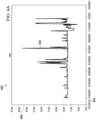
- FIGS. 4A and 4B are graphs 400, 450 showing examples of a molecular weight (MW) plot 402 and a heating value plot 452.
- the MW plot is plotted relative to a time axis 404 and a MW axis 406.
- the heating value plot 452 is plotted relative to a time axis 454 and a heating value axis 456.
- Graphs 400 and 450 demonstrate that the molecular weight and heating value of the flared gasses fluctuates based on the sources of the flaring events which is computed by implementations of the present invention.
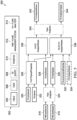
- FIG. 5 is a block diagram showing an example of a system data flow 500 for flare analysis, according to some implementations of the present invention.
- a key 502 shows line styles for elements of the system data flow 500, including tables 504, views 506, C# scripts 508, and business intelligence (BI) units 510 for elements related to flare analyzers (FA) 512 and flare monitoring systems (FMS) 514.
- BI business intelligence
- Elements of the system data flow 500 include FMS.factDevice table 516, FMS.factHeader table 518, FA.component table 520; FA.device table 522, flare analyzer script(s) 524, FA.D_PhysicalProperties view 526; FA.factDevice table 528, FA.factHeader table 530, FA.environmentalPotential table 532, FA.AnalyzerDevice table 534, FA.FD_AnalyzerDevice view 536, FA.FD_FH_AnalyzerHeader view 538, flare analyzer script(s) 540, FA.AnalyzerDevice table 542, and FA.AnalyzerHeader table 544.
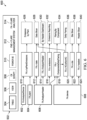
- FIG. 6 is a block diagram showing an example of a system data flow 600 for flare analysis, according to some implementations of the present invention.
- the system data flow 600 includes some of the same elements and types of elements as the system data flow 500 of FIG. 5 . Together, data flows 500 and 600 are used for flare analysis.
- the system data flow 600 includes FA.AnalyzerDevice table 602, FA.plant table 604, FA.AnalyzerHeader table 606, FA.device table 608, FA.v_byPlantEmissions 610, FA.v_date view 612, FA.v_AnalyzerHeader view 614, FA.v_emissions view 616, FA.v_ComponentsDailyFlaring view 618, FA.v_HCvsNonHC view 620, FA.v_site, view 622 FA.v_headers view 624, Emissions by Plant BI 626, Date Slicer BI 628, By Header Dashboard BI 630, Emissions Reporting BI 632, Flaring by Component BI 634, Daily Flaring BI 636, Site Slicer BI 638, and Header Slicer BI 640.
- FA.AnalyzerDevice table 542 and FA.AnalyzerHeader table 544 can be used as the main data sources for the POWER BI elements, including Emissions by Plant 626, Date Slicer 628, By Header Dashboard 630, Emissions Reporting 632, Flaring by Component 634. and Daily Flaring 636.
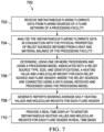
- FIG. 7 is a flowchart of an example of a method 700 for generating a real-time display to monitor instantaneous heating values and molecular weights for flare headers, according to some implementations of the present invention.
- method 700 can be performed, for example, by any suitable system, environment, software, and hardware, or a combination of systems, environments, software, and hardware, as appropriate.
- various steps of method 700 can be run in parallel, in combination, in loops, or in any order.
- instantaneous flaring flowrate data is received from flaring sources of a flare network of a processing facility.
- flaring data can be received from an onshore or offshore oil or gas production site or refinery. From 702, method 700 proceeds to 704.
- the instantaneous flaring flowrate data is analyzed in conjunction with the physical properties of a relief source using a heat and material balance of the processing facility.
- analyzing the instantaneous flaring flowrate data includes using a data flow network of tables, views, scripts, and power business intelligence (BI) elements, as described with reference to FIGS. 5 and 6 .
- the data flow network of tables, views, and scripts can further be stored in a data historian model operable to store into memory: parameters of flare-through elements concerning a relationship between generated data signals and a quantitative heating value and a molecular weight at each relief source; data associated with a heating value and a molecular weight of the flare header; and data associated with a heating value and a molecular weight for each plant. From 704, method 700 proceeds to 706.
- a heating value and a molecular weight for each relief source and flare header are determined using one or more processors and using a processing model associated with a relief source type, size, and identifications. This can be part of performing a comprehensive heating value and molecular weight calculation for each flare header throughout the flare network.
- the relief sources can be connected using a data signal received and processed using the processing model.
- graphs 400 and 450 can be generated that display the MW plot 402 and the heating value plot 452, respectively. The calculations can be based on Equations (1) to (6), for example. From 706, method 700 proceeds to 708.
- reports are generated showing average daily heating values and molecular weights for each flare header.
- generating reports can include identifying whether particular flaring events are of a routine or non-routine nature, a flared volume, and a contribution of the flare-through elements to the flared volume.
- the reports can be accessible from within a user interface, such as described with reference to FIG. 2 . From 708, method 700 proceeds to 710.
- a real-time display is provided to monitor instantaneous heating values and molecular weights for each flare header in real time basis.
- providing the real-time display can include displaying, for each flare header, heating values over time.
- the real-time display can include displaying molecular weights and a heating value.
- providing the real-time display can include displaying, for each flare header, a graph showing significant fluctuations in reading relative to a time period.
- FIG. 8 is a block diagram of an example computer system 800 used to provide computational functionalities associated with described algorithms, methods, functions, processes, flows, and procedures described herein, according to some implementations of the present invention.
- the illustrated computer 802 is intended to encompass any computing device such as a server, a desktop computer, a laptop/notebook computer, a wireless data port, a smart phone, a personal data assistant (PDA), a tablet computing device, or one or more processors within these devices, including physical instances, virtual instances, or both.
- the computer 802 can include input devices such as keypads, keyboards, and touch screens that can accept user information.
- the computer 802 can include output devices that can convey information associated with the operation of the computer 802.
- the information can include digital data, visual data, audio information, or a combination of information.
- the information can be presented in a graphical user interface (UI) (or GUI).
- UI graphical user interface
- the computer 802 can serve in a role as a client, a network component, a server, a database, a persistency, or components of a computer system for performing the subject matter described herein.
- the illustrated computer 802 is communicably coupled with a network 830.
- one or more components of the computer 802 can be configured to operate within different environments, including cloud-computing-based environments, local environments, global environments, and combinations of environments.
- the computer 802 is an electronic computing device operable to receive, transmit, process, store, and manage data and information associated with the described subject matter. According to some implementations, the computer 802 can also include, or be communicably coupled with, an application server, an email server, a web server, a caching server, a streaming data server, or a combination of servers.
- the computer 802 can receive requests over network 830 from a client application (for example, executing on another computer 802).
- the computer 802 can respond to the received requests by processing the received requests using software applications. Requests can also be sent to the computer 802 from internal users (for example, from a command console), external (or third) parties, automated applications, entities, individuals, systems, and computers.
- Each of the components of the computer 802 can communicate using a system bus 803.
- any or all of the components of the computer 802, including hardware or software components can interface with each other or the interface 804 (or a combination of both) over the system bus 803.
- Interfaces can use an application programming interface (API) 812, a service layer 813, or a combination of the API 812 and service layer 813.
- the API 812 can include specifications for routines, data structures, and object classes.
- the API 812 can be either computer-language independent or dependent.
- the API 812 can refer to a complete interface, a single function, or a set of APIs.
- the service layer 813 can provide software services to the computer 802 and other components (whether illustrated or not) that are communicably coupled to the computer 802.
- the functionality of the computer 802 can be accessible for all service consumers using this service layer.
- Software services, such as those provided by the service layer 813 can provide reusable, defined functionalities through a defined interface.
- the interface can be software written in JAVA, C++, or a language providing data in extensible markup language (XML) format.
- the API 812 or the service layer 813 can be stand-alone components in relation to other components of the computer 802 and other components communicably coupled to the computer 802.
- any or all parts of the API 812 or the service layer 813 can be implemented as child or sub-modules of another software module, enterprise application, or hardware module without departing from the scope of the present invention.
- the computer 802 includes an interface 804. Although illustrated as a single interface 804 in FIG. 8 , two or more interfaces 804 can be used according to particular needs, desires, or particular implementations of the computer 802 and the described functionality.
- the interface 804 can be used by the computer 802 for communicating with other systems that are connected to the network 830 (whether illustrated or not) in a distributed environment.
- the interface 804 can include, or be implemented using, logic encoded in software or hardware (or a combination of software and hardware) operable to communicate with the network 830. More specifically, the interface 804 can include software supporting one or more communication protocols associated with communications. As such, the network 830 or the interface's hardware can be operable to communicate physical signals within and outside of the illustrated computer 802.
- the computer 802 includes a processor 805. Although illustrated as a single processor 805 in FIG. 8 , two or more processors 805 can be used according to particular needs, desires, or particular implementations of the computer 802 and the described functionality. Generally, the processor 805 can execute instructions and can manipulate data to perform the operations of the computer 802, including operations using algorithms, methods, functions, processes, flows, and procedures as described herein.
- the computer 802 also includes a database 806 that can hold data for the computer 802 and other components connected to the network 830 (whether illustrated or not).
- database 806 can be an in-memory, conventional, or a database storing data consistent with the present invention.
- database 806 can be a combination of two or more different database types (for example, hybrid in-memory and conventional databases) according to particular needs, desires, or particular implementations of the computer 802 and the described functionality.
- two or more databases can be used according to particular needs, desires, or particular implementations of the computer 802 and the described functionality.
- database 806 is illustrated as an internal component of the computer 802, in alternative implementations, database 806 can be external to the computer 802.
- the computer 802 also includes a memory 807 that can hold data for the computer 802 or a combination of components connected to the network 830 (whether illustrated or not).
- Memory 807 can store any data consistent with the present invention.
- memory 807 can be a combination of two or more different types of memory (for example, a combination of semiconductor and magnetic storage) according to particular needs, desires, or particular implementations of the computer 802 and the described functionality.
- two or more memories 807 can be used according to particular needs, desires, or particular implementations of the computer 802 and the described functionality. While memory 807 is illustrated as an internal component of the computer 802, in alternative implementations, memory 807 can be external to the computer 802.
- the application 808 can be an algorithmic software engine providing functionality according to particular needs, desires, or particular implementations of the computer 802 and the described functionality.
- application 808 can serve as one or more components, modules, or applications.
- the application 808 can be implemented as multiple applications 808 on the computer 802.
- the application 808 can be external to the computer 802.
- the computer 802 can also include a power supply 814.
- the power supply 814 can include a rechargeable or non-rechargeable battery that can be configured to be either user- or non-user-replaceable.
- the power supply 814 can include power-conversion and management circuits, including recharging, standby, and power management functionalities.
- the power-supply 814 can include a power plug to allow the computer 802 to be plugged into a wall socket or a power source to, for example, power the computer 802 or recharge a rechargeable battery.
- computers 802 there can be any number of computers 802 associated with, or external to, a computer system containing computer 802, with each computer 802 communicating over network 830. Further, the terms “client,” “user,” and other appropriate terminology can be used interchangeably, as appropriate, without departing from the scope of the present invention. Moreover, the present invention contemplates that many users can use one computer 802 and one user can use multiple computers 802.
- Implementations of the subject matter and the functional operations described in this specification can be implemented in digital electronic circuitry, in tangibly embodied computer software or firmware, in computer hardware, including the structures disclosed in this specification and their structural equivalents, or in combinations of one or more of them.
- Software implementations of the described subject matter can be implemented as one or more computer programs.
- Each computer program can include one or more modules of computer program instructions encoded on a tangible, non-transitory, computer-readable computer-storage medium for execution by, or to control the operation of, data processing apparatus.
- the program instructions can be encoded in/on an artificially generated propagated signal.
- the signal can be a machine-generated electrical, optical, or electromagnetic signal that is generated to encode information for transmission to a suitable receiver apparatus for execution by a data processing apparatus.
- the computer-storage medium can be a machine-readable storage device, a machine-readable storage substrate, a random or serial access memory device, or a combination of computer-storage mediums.
- a data processing apparatus can encompass all kinds of apparatuses, devices, and machines for processing data, including by way of example, a programmable processor, a computer, or multiple processors or computers.
- the apparatus can also include special purpose logic circuitry including, for example, a central processing unit (CPU), a field-programmable gate array (FPGA), or an application-specific integrated circuit (ASIC).
- CPU central processing unit
- FPGA field-programmable gate array
- ASIC application-specific integrated circuit
- the data processing apparatus or special purpose logic circuitry can be hardware- or software-based (or a combination of both hardware- and software-based).
- the apparatus can optionally include code that creates an execution environment for computer programs, for example, code that constitutes processor firmware, a protocol stack, a database management system, an operating system, or a combination of execution environments.
- code that constitutes processor firmware for example, code that constitutes processor firmware, a protocol stack, a database management system, an operating system, or a combination of execution environments.
- the present disclosure contemplates the use of data processing apparatuses with or without conventional operating systems, such as LINUX, UNIX, WINDOWS, MAC OS, ANDROID, or IOS.
- a computer program which can also be referred to or described as a program, software, a software application, a module, a software module, a script, or code, can be written in any form of programming language.
- Programming languages can include, for example, compiled languages, interpreted languages, declarative languages, or procedural languages.
- Programs can be deployed in any form, including as stand-alone programs, modules, components, subroutines, or units for use in a computing environment.
- a computer program can, but need not, correspond to a file in a file system.
- a program can be stored in a portion of a file that holds other programs or data, for example, one or more scripts stored in a markup language document, in a single file dedicated to the program in question, or in multiple coordinated files storing one or more modules, sub-programs, or portions of code.
- a computer program can be deployed for execution on one computer or on multiple computers that are located, for example, at one site or distributed across multiple sites that are interconnected by a communication network. While portions of the programs illustrated in the various figures may be shown as individual modules that implement the various features and functionality through various objects, methods, or processes, the programs can instead include a number of sub-modules, third-party services, components, and libraries. Conversely, the features and functionality of various components can be combined into single components as appropriate. Thresholds used to make computational determinations can be statically, dynamically, or both statically and dynamically determined.
- the methods, processes, or logic flows described in this specification can be performed by one or more programmable computers executing one or more computer programs to perform functions by operating on input data and generating output.
- the methods, processes, or logic flows can also be performed by, and apparatus can also be implemented as, special purpose logic circuitry, for example, a CPU, an FPGA, or an ASIC.
- Computers suitable for the execution of a computer program can be based on one or more of general and special purpose microprocessors and other kinds of CPUs.
- the elements of a computer are a CPU for performing or executing instructions and one or more memory devices for storing instructions and data.
- a CPU can receive instructions and data from (and write data to) a memory.
- GPUs Graphics processing units
- the GPUs can provide specialized processing that occurs in parallel to processing performed by CPUs.
- the specialized processing can include artificial intelligence (AI) applications and processing, for example.
- GPUs can be used in GPU clusters or in multi-GPU computing.
- a computer can include, or be operatively coupled to, one or more mass storage devices for storing data.
- a computer can receive data from, and transfer data to, the mass storage devices including, for example, magnetic, magneto-optical disks, or optical disks.
- a computer can be embedded in another device, for example, a mobile telephone, a personal digital assistant (PDA), a mobile audio or video player, a game console, a global positioning system (GPS) receiver, or a portable storage device such as a universal serial bus (USB) flash drive.
- PDA personal digital assistant
- GPS global positioning system
- USB universal serial bus
- Computer-readable media (transitory or non-transitory, as appropriate) suitable for storing computer program instructions and data can include all forms of permanent/non-permanent and volatile/non-volatile memory, media, and memory devices.
- Computer-readable media can include, for example, semiconductor memory devices such as random access memory (RAM), read-only memory (ROM), phase change memory (PRAM), static random access memory (SRAM), dynamic random access memory (DRAM), erasable programmable read-only memory (EPROM), electrically erasable programmable read-only memory (EEPROM), and flash memory devices.
- Computer-readable media can also include, for example, magnetic devices such as tape, cartridges, cassettes, and internal/removable disks.
- Computer-readable media can also include magneto-optical disks and optical memory devices and technologies including, for example, digital video disc (DVD), CD-ROM, DVD+/-R, DVD-RAM, DVD-ROM, HD-DVD, and BLU-RAY.
- the memory can store various objects or data, including caches, classes, frameworks, applications, modules, backup data, jobs, web pages, web page templates, data structures, database tables, repositories, and dynamic information. Types of objects and data stored in memory can include parameters, variables, algorithms, instructions, rules, constraints, and references. Additionally, the memory can include logs, policies, security or access data, and reporting files.
- the processor and the memory can be supplemented by, or incorporated into, special purpose logic circuitry.
- Implementations of the subject matter described in the present invention can be implemented on a computer having a display device for providing interaction with a user, including displaying information to (and receiving input from) the user.
- display devices can include, for example, a cathode ray tube (CRT), a liquid crystal display (LCD), a light-emitting diode (LED), and a plasma monitor.
- Display devices can include a keyboard and pointing devices including, for example, a mouse, a trackball, or a trackpad.
- User input can also be provided to the computer through the use of a touchscreen, such as a tablet computer surface with pressure sensitivity or a multi-touch screen using capacitive or electric sensing.
- a computer can interact with a user by sending documents to, and receiving documents from, a device that the user uses.
- the computer can send web pages to a web browser on a user's client device in response to requests received from the web browser.
- GUI graphical user interface
- GUI can be used in the singular or the plural to describe one or more graphical user interfaces and each of the displays of a particular graphical user interface. Therefore, a GUI can represent any graphical user interface, including, but not limited to, a web browser, a touch-screen, or a command line interface (CLI) that processes information and efficiently presents the information results to the user.
- a GUI can include a plurality of user interface (UI) elements, some or all associated with a web browser, such as interactive fields, pull-down lists, and buttons. These and other UI elements can be related to or represent the functions of the web browser.
- UI user interface
- Implementations of the subject matter described in this specification can be implemented in a computing system that includes a back-end component, for example, as a data server, or that includes a middleware component, for example, an application server.
- the computing system can include a front-end component, for example, a client computer having one or both of a graphical user interface or a Web browser through which a user can interact with the computer.
- the components of the system can be interconnected by any form or medium of wireline or wireless digital data communication (or a combination of data communication) in a communication network.
- Examples of communication networks include a local area network (LAN), a radio access network (RAN), a metropolitan area network (MAN), a wide area network (WAN), Worldwide Interoperability for Microwave Access (WIMAX), a wireless local area network (WLAN) (for example, using 802.11 a/b/g/n or 802.20 or a combination of protocols), all or a portion of the Internet, or any other communication system or systems at one or more locations (or a combination of communication networks).
- the network can communicate with, for example, Internet Protocol (IP) packets, frame relay frames, asynchronous transfer mode (ATM) cells, voice, video, data, or a combination of communication types between network addresses.
- IP Internet Protocol
- ATM asynchronous transfer mode
- the computing system can include clients and servers.
- a client and server can generally be remote from each other and can typically interact through a communication network.
- the relationship of client and server can arise by virtue of computer programs running on the respective computers and having a client-server relationship.
- Cluster file systems can be any file system type accessible from multiple servers for read and update. Locking or consistency tracking may not be necessary since the locking of exchange file system can be done at application layer. Furthermore, Unicode data files can be different from non-Unicode data files.
- any claimed implementation is considered to be applicable to at least a computer-implemented method; a non-transitory, computer-readable medium storing computer-readable instructions to perform the computer-implemented method; and a computer system including a computer memory interoperably coupled with a hardware processor configured to perform the computer-implemented method or the instructions stored on the non-transitory, computer-readable medium.
Landscapes
- Engineering & Computer Science (AREA)
- Chemical & Material Sciences (AREA)
- Health & Medical Sciences (AREA)
- Life Sciences & Earth Sciences (AREA)
- General Engineering & Computer Science (AREA)
- Mechanical Engineering (AREA)
- Environmental & Geological Engineering (AREA)
- Analytical Chemistry (AREA)
- Physics & Mathematics (AREA)
- Biochemistry (AREA)
- General Health & Medical Sciences (AREA)
- General Physics & Mathematics (AREA)
- Immunology (AREA)
- Pathology (AREA)
- Medicinal Chemistry (AREA)
- Food Science & Technology (AREA)
- Combustion & Propulsion (AREA)
- Testing And Monitoring For Control Systems (AREA)
Claims (9)
- Computerimplementiertes Verfahren, umfassend:Empfangen (702) von Momentandaten zur Abfackelungsdurchflussrate von Abfackelungsquellen eines Fackelnetzes einer Verarbeitungsanlage;Analysieren (704) der Momentandaten zur Abfackelungsdurchflussrate in Verbindung mit den physikalischen Eigenschaften von Reliefquellen, die aus einer Wärme- und Materialbilanz der Verarbeitungsanlage erhalten werden;Bestimmen (706), unter Verwendung eines Verarbeitungsmodells, das einem Typ, einer Größe und Identifikationen einer Reliefquelle zugeordnet ist, eines Heizwerts und eines Molekulargewichts für jede Reliefquelle und jeden Fackelkopf, wobei die Reliefquellen unter Verwendung eines Datensignals verbunden sind, das unter Verwendung des Verarbeitungsmodells empfangen und verarbeitet wird;Erzeugen (708) von Berichten, die durchschnittliche tägliche Heizwerte und Molekulargewichte für jeden Fackelkopf zeigen; undBereitstellen (710) einer Echtzeitanzeige (200, 300, 400, 450) zum Überwachen momentaner Heizwerte und Molekulargewichte für jeden Fackelkopf auf Echtzeitbasis.
- Computerimplementiertes Verfahren nach Anspruch 1, wobei das Analysieren der Momentandaten zur Abfackelungsdurchflussrate ein Verwenden eines Datenflussnetzes (500, 600) von Tabellen (516, 518, 520, 522, 528, 530, 532, 534, 542, 544, 602, 604, 606, 608), Ansichten (526, 536, 538, 610, 612, 614, 616, 618, 620, 622, 624) und Skripten (524, 540) einschließt, die ferner in einem Datenhistorikermodell gespeichert sind, das betreibbar ist, um in einem Speicher zu speichern:Parameter von Flare-Through-Elementen, die eine Beziehung zwischen erzeugten Datensignalen und einem quantitativen Heizwert und einem Molekulargewicht an jeder Reliefquelle betreffen;Daten, die einem Heizwert und einem Molekulargewicht des Fackelkopfs zugeordnet sind; undDaten, die einem Heizwert und einem Molekulargewicht für jede Anlage zugeordnet sind.
- Computerimplementiertes Verfahren nach Anspruch 1, wobei das Erzeugen von Berichten ein Identifizieren, ob bestimmte Abfackelungsereignisse routinemäßiger oder nichtroutinemäßiger Art sind, und ein Identifizieren eines abgefackelten Volumens und eines Beitrags von Flare-Through-Elementen zum abgefackelten Volumen einschließt.
- Computerimplementiertes Verfahren nach Anspruch 1, wobei das Bereitstellen der Echtzeitanzeige ein Anzeigen, für jeden Fackelkopf, von Heizwerten im Laufe der Zeit einschließt.
- Computerimplementiertes Verfahren nach Anspruch 1, wobei das Bereitstellen der Echtzeitanzeige ein Anzeigen, für jeden Fackelkopf, von Gesamtemissionen, CO2-Emissionen, Molekulargewichten und einem Heizwert einschließt.
- Computerimplementiertes Verfahren nach Anspruch 1, wobei das Bereitstellen der Echtzeitanzeige ein Anzeigen, für jeden Fackelkopf, eines Graphen, der signifikante Schwankungen in Messwerten relativ zu einer Zeitperiode zeigt, einschließt.
- Computerimplementiertes Verfahren nach Anspruch 1, wobei das Bestimmen des Heizwerts und des Molekulargewichts für jede Reliefquelle und jeden Fackelkopf ein Erzeugen eines oder mehrerer Heizwertgraphen und Molekulargewichtsgraphen, die Werte im Laufe der Zeit anzeigen, einschließt.
- Nichttransistorisches computerlesbares Medium, das eine oder mehrere Anweisungen speichert, die durch ein Computersystem ausführbar sind, um Operationen durchzuführen, die das Verfahren nach einem der Ansprüche 1 bis 7 umfassen.
- Computerimplementiertes System (800), umfassend:einen oder mehrere Prozessoren (805) undein nichttransistorisches computerlesbares Speichermedium, das mit dem einen oder den mehreren Prozessoren gekoppelt ist und Programmieranweisungen (807) zur Ausführung durch den einen oder die mehreren Prozessoren speichert, wobei die Programmieranweisungen den einen oder die mehreren Prozessoren anweisen, Operationen durchzuführen, die das Verfahren nach einem der Ansprüche 1 bis 7 umfassen.
Applications Claiming Priority (2)
| Application Number | Priority Date | Filing Date | Title |
|---|---|---|---|
| US17/487,446 US11747315B2 (en) | 2021-09-28 | 2021-09-28 | Flare system heating value monitoring meter |
| PCT/US2022/077030 WO2023056235A1 (en) | 2021-09-28 | 2022-09-26 | Flare system heating value monitoring meter |
Publications (2)
| Publication Number | Publication Date |
|---|---|
| EP4384752A1 EP4384752A1 (de) | 2024-06-19 |
| EP4384752B1 true EP4384752B1 (de) | 2025-01-01 |
Family
ID=83692985
Family Applications (1)
| Application Number | Title | Priority Date | Filing Date |
|---|---|---|---|
| EP22790178.2A Active EP4384752B1 (de) | 2021-09-28 | 2022-09-26 | Heizwertüberwachungsmesser für fackelsystem |
Country Status (4)
| Country | Link |
|---|---|
| US (1) | US11747315B2 (de) |
| EP (1) | EP4384752B1 (de) |
| CN (1) | CN117999440A (de) |
| WO (1) | WO2023056235A1 (de) |
Families Citing this family (4)
| Publication number | Priority date | Publication date | Assignee | Title |
|---|---|---|---|---|
| US11795810B2 (en) | 2021-09-27 | 2023-10-24 | Saudi Arabian Oil Company | Flare systems analyzer |
| US12516810B2 (en) | 2021-10-26 | 2026-01-06 | Saudi Arabian Oil Company | Flare systems emissions analyzer |
| US12474049B2 (en) | 2022-12-27 | 2025-11-18 | Saudi Arabian Oil Company | Automatically igniting gas flares |
| US12422139B2 (en) | 2024-01-04 | 2025-09-23 | Saudi Arabian Oil Company | Optimizing purge gas flows through a flare gas network |
Family Cites Families (14)
| Publication number | Priority date | Publication date | Assignee | Title |
|---|---|---|---|---|
| US4202168A (en) | 1977-04-28 | 1980-05-13 | Gulf Research & Development Company | Method for the recovery of power from LHV gas |
| US20030069743A1 (en) | 2001-09-21 | 2003-04-10 | Nordrum Susann B. | System and method for energy and green-house gas inventory management |
| US7440871B2 (en) | 2002-12-09 | 2008-10-21 | Verisae, Inc. | Method and system for tracking and reporting emissions |
| AU2010226995A1 (en) | 2009-10-07 | 2011-04-21 | John Zink Company, Llc | Image Sensing System, Software, Apparatus and Method For Controlling Combustion Equipment |
| DE102009054316A1 (de) | 2009-11-24 | 2011-05-26 | E.On Ruhrgas Ag | Verfahren zur Bestimmung des bei der Verbrennung von Brenngas emittierten Kohlenstoffdioxids |
| US10029291B2 (en) | 2013-01-02 | 2018-07-24 | Q.E.D. Environmental Systems, Inc. | Devices and methods for landfill gas well monitoring and control |
| US9142111B2 (en) | 2013-03-15 | 2015-09-22 | Saudi Arabian Oil Company | Flare network monitorng system and method |
| US20150050603A1 (en) | 2013-08-14 | 2015-02-19 | Danny Edward Griffin | Dual-Pressure Flare System and Method of Use |
| US20150260397A1 (en) * | 2014-03-17 | 2015-09-17 | Honeywell International Inc. | Integrated smoke monitoring and control system for flaring operations |
| US10746400B2 (en) | 2016-06-28 | 2020-08-18 | General Electric Company | Integrated flare combustion control |
| US11047573B2 (en) * | 2018-02-05 | 2021-06-29 | Chevron Phillips Chemical Company Lp | Flare monitoring and control method and apparatus |
| US10850314B2 (en) | 2018-06-04 | 2020-12-01 | Daniel W. Chambers | Remote gas monitoring and flare control system |
| US12044641B2 (en) | 2020-05-29 | 2024-07-23 | Baker Hughes Oilfield Operations Llc | Emission monitoring of flare systems |
| US12516810B2 (en) | 2021-10-26 | 2026-01-06 | Saudi Arabian Oil Company | Flare systems emissions analyzer |
-
2021
- 2021-09-28 US US17/487,446 patent/US11747315B2/en active Active
-
2022
- 2022-09-26 EP EP22790178.2A patent/EP4384752B1/de active Active
- 2022-09-26 WO PCT/US2022/077030 patent/WO2023056235A1/en not_active Ceased
- 2022-09-26 CN CN202280065068.0A patent/CN117999440A/zh active Pending
Also Published As
| Publication number | Publication date |
|---|---|
| CN117999440A (zh) | 2024-05-07 |
| US20230096405A1 (en) | 2023-03-30 |
| US11747315B2 (en) | 2023-09-05 |
| EP4384752A1 (de) | 2024-06-19 |
| WO2023056235A1 (en) | 2023-04-06 |
Similar Documents
| Publication | Publication Date | Title |
|---|---|---|
| EP4384752B1 (de) | Heizwertüberwachungsmesser für fackelsystem | |
| US12516810B2 (en) | Flare systems emissions analyzer | |
| EP4384753B1 (de) | Fackelsystemanalysator | |
| US11263374B2 (en) | Bisection numerical algorithm coupled with pressure deviation method to determine the size and location of a leak in a pipeline | |
| US20240185149A1 (en) | Forecasting energy demand and co2 emissions for a gas processing plant integrated with power generation facilities | |
| US10983513B1 (en) | Automated algorithm and real-time system to detect MPFM preventive maintenance activities | |
| US20240176932A1 (en) | Continuous online validation of process measurements in digital twins | |
| WO2024086107A1 (en) | Validation and optimization of industrial carbon footprint emissions reduction | |
| US12044818B2 (en) | System for in situ estimation of sub-erosion production rates in gas wells | |
| US20240248467A1 (en) | Automatic online flaring data validation and reporting | |
| US11078773B2 (en) | Performing continuous daily production allocation | |
| US20240426741A1 (en) | Corrosion treatment systems | |
| US12110777B2 (en) | Auto-correction for water cut measurements from multi-phase flowmeter in undersaturated oil wells | |
| US12180829B2 (en) | Lean mono-ethylene glycol (MEG) concentration with presence of inorganic salt virtual meter | |
| US11432054B2 (en) | Fire water network leak detection system | |
| US12051486B2 (en) | Utilizing hydraulic simulation to evaluate quality of water in salt water disposal systems | |
| US12387117B2 (en) | Injector riskiness score (IRS) matrix | |
| US20250278082A1 (en) | Natural gas liquids quality digitalized analytics and predictive solution |
Legal Events
| Date | Code | Title | Description |
|---|---|---|---|
| STAA | Information on the status of an ep patent application or granted ep patent |
Free format text: STATUS: UNKNOWN |
|
| STAA | Information on the status of an ep patent application or granted ep patent |
Free format text: STATUS: THE INTERNATIONAL PUBLICATION HAS BEEN MADE |
|
| PUAI | Public reference made under article 153(3) epc to a published international application that has entered the european phase |
Free format text: ORIGINAL CODE: 0009012 |
|
| STAA | Information on the status of an ep patent application or granted ep patent |
Free format text: STATUS: REQUEST FOR EXAMINATION WAS MADE |
|
| 17P | Request for examination filed |
Effective date: 20240312 |
|
| AK | Designated contracting states |
Kind code of ref document: A1 Designated state(s): AL AT BE BG CH CY CZ DE DK EE ES FI FR GB GR HR HU IE IS IT LI LT LU LV MC MK MT NL NO PL PT RO RS SE SI SK SM TR |
|
| GRAP | Despatch of communication of intention to grant a patent |
Free format text: ORIGINAL CODE: EPIDOSNIGR1 |
|
| STAA | Information on the status of an ep patent application or granted ep patent |
Free format text: STATUS: GRANT OF PATENT IS INTENDED |
|
| P01 | Opt-out of the competence of the unified patent court (upc) registered |
Free format text: CASE NUMBER: APP_40309/2024 Effective date: 20240707 |
|
| DAV | Request for validation of the european patent (deleted) | ||
| DAX | Request for extension of the european patent (deleted) | ||
| INTG | Intention to grant announced |
Effective date: 20240730 |
|
| GRAS | Grant fee paid |
Free format text: ORIGINAL CODE: EPIDOSNIGR3 |
|
| GRAA | (expected) grant |
Free format text: ORIGINAL CODE: 0009210 |
|
| STAA | Information on the status of an ep patent application or granted ep patent |
Free format text: STATUS: THE PATENT HAS BEEN GRANTED |
|
| AK | Designated contracting states |
Kind code of ref document: B1 Designated state(s): AL AT BE BG CH CY CZ DE DK EE ES FI FR GB GR HR HU IE IS IT LI LT LU LV MC MK MT NL NO PL PT RO RS SE SI SK SM TR |
|
| REG | Reference to a national code |
Ref country code: GB Ref legal event code: FG4D |
|
| REG | Reference to a national code |
Ref country code: CH Ref legal event code: EP |
|
| REG | Reference to a national code |
Ref country code: DE Ref legal event code: R096 Ref document number: 602022009425 Country of ref document: DE |
|
| REG | Reference to a national code |
Ref country code: IE Ref legal event code: FG4D |
|
| REG | Reference to a national code |
Ref country code: LT Ref legal event code: MG9D |
|
| REG | Reference to a national code |
Ref country code: NL Ref legal event code: MP Effective date: 20250101 |
|
| REG | Reference to a national code |
Ref country code: AT Ref legal event code: MK05 Ref document number: 1756584 Country of ref document: AT Kind code of ref document: T Effective date: 20250101 |
|
| PG25 | Lapsed in a contracting state [announced via postgrant information from national office to epo] |
Ref country code: NL Free format text: LAPSE BECAUSE OF FAILURE TO SUBMIT A TRANSLATION OF THE DESCRIPTION OR TO PAY THE FEE WITHIN THE PRESCRIBED TIME-LIMIT Effective date: 20250101 |
|
| PG25 | Lapsed in a contracting state [announced via postgrant information from national office to epo] |
Ref country code: FI Free format text: LAPSE BECAUSE OF FAILURE TO SUBMIT A TRANSLATION OF THE DESCRIPTION OR TO PAY THE FEE WITHIN THE PRESCRIBED TIME-LIMIT Effective date: 20250101 |
|
| PG25 | Lapsed in a contracting state [announced via postgrant information from national office to epo] |
Ref country code: PL Free format text: LAPSE BECAUSE OF FAILURE TO SUBMIT A TRANSLATION OF THE DESCRIPTION OR TO PAY THE FEE WITHIN THE PRESCRIBED TIME-LIMIT Effective date: 20250101 |
|
| PG25 | Lapsed in a contracting state [announced via postgrant information from national office to epo] |
Ref country code: ES Free format text: LAPSE BECAUSE OF FAILURE TO SUBMIT A TRANSLATION OF THE DESCRIPTION OR TO PAY THE FEE WITHIN THE PRESCRIBED TIME-LIMIT Effective date: 20250101 |
|
| PG25 | Lapsed in a contracting state [announced via postgrant information from national office to epo] |
Ref country code: NO Free format text: LAPSE BECAUSE OF FAILURE TO SUBMIT A TRANSLATION OF THE DESCRIPTION OR TO PAY THE FEE WITHIN THE PRESCRIBED TIME-LIMIT Effective date: 20250401 Ref country code: IS Free format text: LAPSE BECAUSE OF FAILURE TO SUBMIT A TRANSLATION OF THE DESCRIPTION OR TO PAY THE FEE WITHIN THE PRESCRIBED TIME-LIMIT Effective date: 20250501 |
|
| PG25 | Lapsed in a contracting state [announced via postgrant information from national office to epo] |
Ref country code: HR Free format text: LAPSE BECAUSE OF FAILURE TO SUBMIT A TRANSLATION OF THE DESCRIPTION OR TO PAY THE FEE WITHIN THE PRESCRIBED TIME-LIMIT Effective date: 20250101 |
|
| PG25 | Lapsed in a contracting state [announced via postgrant information from national office to epo] |
Ref country code: PT Free format text: LAPSE BECAUSE OF FAILURE TO SUBMIT A TRANSLATION OF THE DESCRIPTION OR TO PAY THE FEE WITHIN THE PRESCRIBED TIME-LIMIT Effective date: 20250502 Ref country code: LV Free format text: LAPSE BECAUSE OF FAILURE TO SUBMIT A TRANSLATION OF THE DESCRIPTION OR TO PAY THE FEE WITHIN THE PRESCRIBED TIME-LIMIT Effective date: 20250101 |
|
| PG25 | Lapsed in a contracting state [announced via postgrant information from national office to epo] |
Ref country code: BG Free format text: LAPSE BECAUSE OF FAILURE TO SUBMIT A TRANSLATION OF THE DESCRIPTION OR TO PAY THE FEE WITHIN THE PRESCRIBED TIME-LIMIT Effective date: 20250101 Ref country code: GR Free format text: LAPSE BECAUSE OF FAILURE TO SUBMIT A TRANSLATION OF THE DESCRIPTION OR TO PAY THE FEE WITHIN THE PRESCRIBED TIME-LIMIT Effective date: 20250402 |
|
| PG25 | Lapsed in a contracting state [announced via postgrant information from national office to epo] |
Ref country code: AT Free format text: LAPSE BECAUSE OF FAILURE TO SUBMIT A TRANSLATION OF THE DESCRIPTION OR TO PAY THE FEE WITHIN THE PRESCRIBED TIME-LIMIT Effective date: 20250101 |
|
| PG25 | Lapsed in a contracting state [announced via postgrant information from national office to epo] |
Ref country code: CZ Free format text: LAPSE BECAUSE OF FAILURE TO SUBMIT A TRANSLATION OF THE DESCRIPTION OR TO PAY THE FEE WITHIN THE PRESCRIBED TIME-LIMIT Effective date: 20250101 |
|
| PG25 | Lapsed in a contracting state [announced via postgrant information from national office to epo] |
Ref country code: SE Free format text: LAPSE BECAUSE OF FAILURE TO SUBMIT A TRANSLATION OF THE DESCRIPTION OR TO PAY THE FEE WITHIN THE PRESCRIBED TIME-LIMIT Effective date: 20250101 |
|
| REG | Reference to a national code |
Ref country code: DE Ref legal event code: R097 Ref document number: 602022009425 Country of ref document: DE |
|
| PG25 | Lapsed in a contracting state [announced via postgrant information from national office to epo] |
Ref country code: SM Free format text: LAPSE BECAUSE OF FAILURE TO SUBMIT A TRANSLATION OF THE DESCRIPTION OR TO PAY THE FEE WITHIN THE PRESCRIBED TIME-LIMIT Effective date: 20250101 |
|
| PG25 | Lapsed in a contracting state [announced via postgrant information from national office to epo] |
Ref country code: DK Free format text: LAPSE BECAUSE OF FAILURE TO SUBMIT A TRANSLATION OF THE DESCRIPTION OR TO PAY THE FEE WITHIN THE PRESCRIBED TIME-LIMIT Effective date: 20250101 |
|
| PGFP | Annual fee paid to national office [announced via postgrant information from national office to epo] |
Ref country code: DE Payment date: 20250902 Year of fee payment: 4 |
|
| PG25 | Lapsed in a contracting state [announced via postgrant information from national office to epo] |
Ref country code: IT Free format text: LAPSE BECAUSE OF FAILURE TO SUBMIT A TRANSLATION OF THE DESCRIPTION OR TO PAY THE FEE WITHIN THE PRESCRIBED TIME-LIMIT Effective date: 20250101 |
|
| PGFP | Annual fee paid to national office [announced via postgrant information from national office to epo] |
Ref country code: FR Payment date: 20250908 Year of fee payment: 4 |
|
| PG25 | Lapsed in a contracting state [announced via postgrant information from national office to epo] |
Ref country code: EE Free format text: LAPSE BECAUSE OF FAILURE TO SUBMIT A TRANSLATION OF THE DESCRIPTION OR TO PAY THE FEE WITHIN THE PRESCRIBED TIME-LIMIT Effective date: 20250101 |
|
| PG25 | Lapsed in a contracting state [announced via postgrant information from national office to epo] |
Ref country code: RO Free format text: LAPSE BECAUSE OF FAILURE TO SUBMIT A TRANSLATION OF THE DESCRIPTION OR TO PAY THE FEE WITHIN THE PRESCRIBED TIME-LIMIT Effective date: 20250101 |
|
| PG25 | Lapsed in a contracting state [announced via postgrant information from national office to epo] |
Ref country code: SK Free format text: LAPSE BECAUSE OF FAILURE TO SUBMIT A TRANSLATION OF THE DESCRIPTION OR TO PAY THE FEE WITHIN THE PRESCRIBED TIME-LIMIT Effective date: 20250101 |
|
| PLBE | No opposition filed within time limit |
Free format text: ORIGINAL CODE: 0009261 |
|
| STAA | Information on the status of an ep patent application or granted ep patent |
Free format text: STATUS: NO OPPOSITION FILED WITHIN TIME LIMIT |
|
| 26N | No opposition filed |
Effective date: 20251002 |