EP4383541A1 - Hybridmodus-steuerverfahren - Google Patents
Hybridmodus-steuerverfahren Download PDFInfo
- Publication number
- EP4383541A1 EP4383541A1 EP23172844.5A EP23172844A EP4383541A1 EP 4383541 A1 EP4383541 A1 EP 4383541A1 EP 23172844 A EP23172844 A EP 23172844A EP 4383541 A1 EP4383541 A1 EP 4383541A1
- Authority
- EP
- European Patent Office
- Prior art keywords
- mode
- resonant converter
- llc resonant
- frequency
- duty cycle
- Prior art date
- Legal status (The legal status is an assumption and is not a legal conclusion. Google has not performed a legal analysis and makes no representation as to the accuracy of the status listed.)
- Pending
Links
Images


Classifications
-
- H—ELECTRICITY
- H02—GENERATION; CONVERSION OR DISTRIBUTION OF ELECTRIC POWER
- H02M—APPARATUS FOR CONVERSION BETWEEN AC AND AC, BETWEEN AC AND DC, OR BETWEEN DC AND DC, AND FOR USE WITH MAINS OR SIMILAR POWER SUPPLY SYSTEMS; CONVERSION OF DC OR AC INPUT POWER INTO SURGE OUTPUT POWER; CONTROL OR REGULATION THEREOF
- H02M1/00—Details of apparatus for conversion
- H02M1/0003—Details of control, feedback or regulation circuits
- H02M1/0032—Control circuits allowing low power mode operation, e.g. in standby mode
- H02M1/0035—Control circuits allowing low power mode operation, e.g. in standby mode using burst mode control
-
- B—PERFORMING OPERATIONS; TRANSPORTING
- B60—VEHICLES IN GENERAL
- B60L—PROPULSION OF ELECTRICALLY-PROPELLED VEHICLES; SUPPLYING ELECTRIC POWER FOR AUXILIARY EQUIPMENT OF ELECTRICALLY-PROPELLED VEHICLES; ELECTRODYNAMIC BRAKE SYSTEMS FOR VEHICLES IN GENERAL; MAGNETIC SUSPENSION OR LEVITATION FOR VEHICLES; MONITORING OPERATING VARIABLES OF ELECTRICALLY-PROPELLED VEHICLES; ELECTRIC SAFETY DEVICES FOR ELECTRICALLY-PROPELLED VEHICLES
- B60L53/00—Methods of charging batteries, specially adapted for electric vehicles; Charging stations or on-board charging equipment therefor; Exchange of energy storage elements in electric vehicles
- B60L53/20—Methods of charging batteries, specially adapted for electric vehicles; Charging stations or on-board charging equipment therefor; Exchange of energy storage elements in electric vehicles characterised by converters located in the vehicle
- B60L53/24—Using the vehicle's propulsion converter for charging
-
- H—ELECTRICITY
- H02—GENERATION; CONVERSION OR DISTRIBUTION OF ELECTRIC POWER
- H02J—ELECTRIC POWER NETWORKS; CIRCUIT ARRANGEMENTS OR SYSTEMS FOR SUPPLYING OR DISTRIBUTING ELECTRIC POWER; SYSTEMS FOR STORING ELECTRIC ENERGY
- H02J7/00—Circuit arrangements for charging or discharging batteries or for supplying loads from batteries
- H02J7/90—Regulation of charging or discharging current or voltage
-
- H—ELECTRICITY
- H02—GENERATION; CONVERSION OR DISTRIBUTION OF ELECTRIC POWER
- H02M—APPARATUS FOR CONVERSION BETWEEN AC AND AC, BETWEEN AC AND DC, OR BETWEEN DC AND DC, AND FOR USE WITH MAINS OR SIMILAR POWER SUPPLY SYSTEMS; CONVERSION OF DC OR AC INPUT POWER INTO SURGE OUTPUT POWER; CONTROL OR REGULATION THEREOF
- H02M1/00—Details of apparatus for conversion
- H02M1/08—Circuits specially adapted for the generation of control voltages for semiconductor devices incorporated in static converters
- H02M1/088—Circuits specially adapted for the generation of control voltages for semiconductor devices incorporated in static converters for the simultaneous control of series or parallel connected semiconductor devices
-
- H—ELECTRICITY
- H02—GENERATION; CONVERSION OR DISTRIBUTION OF ELECTRIC POWER
- H02M—APPARATUS FOR CONVERSION BETWEEN AC AND AC, BETWEEN AC AND DC, OR BETWEEN DC AND DC, AND FOR USE WITH MAINS OR SIMILAR POWER SUPPLY SYSTEMS; CONVERSION OF DC OR AC INPUT POWER INTO SURGE OUTPUT POWER; CONTROL OR REGULATION THEREOF
- H02M1/00—Details of apparatus for conversion
- H02M1/14—Arrangements for reducing ripples from DC input or output
-
- H—ELECTRICITY
- H02—GENERATION; CONVERSION OR DISTRIBUTION OF ELECTRIC POWER
- H02M—APPARATUS FOR CONVERSION BETWEEN AC AND AC, BETWEEN AC AND DC, OR BETWEEN DC AND DC, AND FOR USE WITH MAINS OR SIMILAR POWER SUPPLY SYSTEMS; CONVERSION OF DC OR AC INPUT POWER INTO SURGE OUTPUT POWER; CONTROL OR REGULATION THEREOF
- H02M3/00—Conversion of DC power input into DC power output
- H02M3/01—Resonant DC/DC converters
-
- H—ELECTRICITY
- H02—GENERATION; CONVERSION OR DISTRIBUTION OF ELECTRIC POWER
- H02M—APPARATUS FOR CONVERSION BETWEEN AC AND AC, BETWEEN AC AND DC, OR BETWEEN DC AND DC, AND FOR USE WITH MAINS OR SIMILAR POWER SUPPLY SYSTEMS; CONVERSION OF DC OR AC INPUT POWER INTO SURGE OUTPUT POWER; CONTROL OR REGULATION THEREOF
- H02M3/00—Conversion of DC power input into DC power output
- H02M3/22—Conversion of DC power input into DC power output with intermediate conversion into AC
- H02M3/24—Conversion of DC power input into DC power output with intermediate conversion into AC by static converters
- H02M3/28—Conversion of DC power input into DC power output with intermediate conversion into AC by static converters using discharge tubes with control electrode or semiconductor devices with control electrode to produce the intermediate AC
- H02M3/325—Conversion of DC power input into DC power output with intermediate conversion into AC by static converters using discharge tubes with control electrode or semiconductor devices with control electrode to produce the intermediate AC using devices of a triode or a transistor type requiring continuous application of a control signal
- H02M3/335—Conversion of DC power input into DC power output with intermediate conversion into AC by static converters using discharge tubes with control electrode or semiconductor devices with control electrode to produce the intermediate AC using devices of a triode or a transistor type requiring continuous application of a control signal using semiconductor devices only
- H02M3/3353—Conversion of DC power input into DC power output with intermediate conversion into AC by static converters using discharge tubes with control electrode or semiconductor devices with control electrode to produce the intermediate AC using devices of a triode or a transistor type requiring continuous application of a control signal using semiconductor devices only having at least two simultaneously operating switches on the input side, e.g. "double forward" or "double (switched) flyback" converter
-
- H—ELECTRICITY
- H02—GENERATION; CONVERSION OR DISTRIBUTION OF ELECTRIC POWER
- H02M—APPARATUS FOR CONVERSION BETWEEN AC AND AC, BETWEEN AC AND DC, OR BETWEEN DC AND DC, AND FOR USE WITH MAINS OR SIMILAR POWER SUPPLY SYSTEMS; CONVERSION OF DC OR AC INPUT POWER INTO SURGE OUTPUT POWER; CONTROL OR REGULATION THEREOF
- H02M3/00—Conversion of DC power input into DC power output
- H02M3/22—Conversion of DC power input into DC power output with intermediate conversion into AC
- H02M3/24—Conversion of DC power input into DC power output with intermediate conversion into AC by static converters
- H02M3/28—Conversion of DC power input into DC power output with intermediate conversion into AC by static converters using discharge tubes with control electrode or semiconductor devices with control electrode to produce the intermediate AC
- H02M3/325—Conversion of DC power input into DC power output with intermediate conversion into AC by static converters using discharge tubes with control electrode or semiconductor devices with control electrode to produce the intermediate AC using devices of a triode or a transistor type requiring continuous application of a control signal
- H02M3/335—Conversion of DC power input into DC power output with intermediate conversion into AC by static converters using discharge tubes with control electrode or semiconductor devices with control electrode to produce the intermediate AC using devices of a triode or a transistor type requiring continuous application of a control signal using semiconductor devices only
- H02M3/33569—Conversion of DC power input into DC power output with intermediate conversion into AC by static converters using discharge tubes with control electrode or semiconductor devices with control electrode to produce the intermediate AC using devices of a triode or a transistor type requiring continuous application of a control signal using semiconductor devices only having several active switching elements
- H02M3/33573—Full-bridge at primary side of an isolation transformer
-
- H—ELECTRICITY
- H02—GENERATION; CONVERSION OR DISTRIBUTION OF ELECTRIC POWER
- H02M—APPARATUS FOR CONVERSION BETWEEN AC AND AC, BETWEEN AC AND DC, OR BETWEEN DC AND DC, AND FOR USE WITH MAINS OR SIMILAR POWER SUPPLY SYSTEMS; CONVERSION OF DC OR AC INPUT POWER INTO SURGE OUTPUT POWER; CONTROL OR REGULATION THEREOF
- H02M3/00—Conversion of DC power input into DC power output
- H02M3/22—Conversion of DC power input into DC power output with intermediate conversion into AC
- H02M3/24—Conversion of DC power input into DC power output with intermediate conversion into AC by static converters
- H02M3/28—Conversion of DC power input into DC power output with intermediate conversion into AC by static converters using discharge tubes with control electrode or semiconductor devices with control electrode to produce the intermediate AC
- H02M3/325—Conversion of DC power input into DC power output with intermediate conversion into AC by static converters using discharge tubes with control electrode or semiconductor devices with control electrode to produce the intermediate AC using devices of a triode or a transistor type requiring continuous application of a control signal
- H02M3/335—Conversion of DC power input into DC power output with intermediate conversion into AC by static converters using discharge tubes with control electrode or semiconductor devices with control electrode to produce the intermediate AC using devices of a triode or a transistor type requiring continuous application of a control signal using semiconductor devices only
- H02M3/33569—Conversion of DC power input into DC power output with intermediate conversion into AC by static converters using discharge tubes with control electrode or semiconductor devices with control electrode to produce the intermediate AC using devices of a triode or a transistor type requiring continuous application of a control signal using semiconductor devices only having several active switching elements
- H02M3/33576—Conversion of DC power input into DC power output with intermediate conversion into AC by static converters using discharge tubes with control electrode or semiconductor devices with control electrode to produce the intermediate AC using devices of a triode or a transistor type requiring continuous application of a control signal using semiconductor devices only having several active switching elements having at least one active switching element at the secondary side of an isolation transformer
- H02M3/33584—Bidirectional converters
-
- H—ELECTRICITY
- H02—GENERATION; CONVERSION OR DISTRIBUTION OF ELECTRIC POWER
- H02J—ELECTRIC POWER NETWORKS; CIRCUIT ARRANGEMENTS OR SYSTEMS FOR SUPPLYING OR DISTRIBUTING ELECTRIC POWER; SYSTEMS FOR STORING ELECTRIC ENERGY
- H02J2207/00—Details of circuit arrangements for charging or discharging batteries or supplying loads from batteries
- H02J2207/20—Charging or discharging characterised by the power electronics converter
-
- H—ELECTRICITY
- H02—GENERATION; CONVERSION OR DISTRIBUTION OF ELECTRIC POWER
- H02M—APPARATUS FOR CONVERSION BETWEEN AC AND AC, BETWEEN AC AND DC, OR BETWEEN DC AND DC, AND FOR USE WITH MAINS OR SIMILAR POWER SUPPLY SYSTEMS; CONVERSION OF DC OR AC INPUT POWER INTO SURGE OUTPUT POWER; CONTROL OR REGULATION THEREOF
- H02M3/00—Conversion of DC power input into DC power output
- H02M3/22—Conversion of DC power input into DC power output with intermediate conversion into AC
- H02M3/24—Conversion of DC power input into DC power output with intermediate conversion into AC by static converters
- H02M3/28—Conversion of DC power input into DC power output with intermediate conversion into AC by static converters using discharge tubes with control electrode or semiconductor devices with control electrode to produce the intermediate AC
- H02M3/325—Conversion of DC power input into DC power output with intermediate conversion into AC by static converters using discharge tubes with control electrode or semiconductor devices with control electrode to produce the intermediate AC using devices of a triode or a transistor type requiring continuous application of a control signal
- H02M3/335—Conversion of DC power input into DC power output with intermediate conversion into AC by static converters using discharge tubes with control electrode or semiconductor devices with control electrode to produce the intermediate AC using devices of a triode or a transistor type requiring continuous application of a control signal using semiconductor devices only
- H02M3/33569—Conversion of DC power input into DC power output with intermediate conversion into AC by static converters using discharge tubes with control electrode or semiconductor devices with control electrode to produce the intermediate AC using devices of a triode or a transistor type requiring continuous application of a control signal using semiconductor devices only having several active switching elements
- H02M3/33576—Conversion of DC power input into DC power output with intermediate conversion into AC by static converters using discharge tubes with control electrode or semiconductor devices with control electrode to produce the intermediate AC using devices of a triode or a transistor type requiring continuous application of a control signal using semiconductor devices only having several active switching elements having at least one active switching element at the secondary side of an isolation transformer
- H02M3/33592—Conversion of DC power input into DC power output with intermediate conversion into AC by static converters using discharge tubes with control electrode or semiconductor devices with control electrode to produce the intermediate AC using devices of a triode or a transistor type requiring continuous application of a control signal using semiconductor devices only having several active switching elements having at least one active switching element at the secondary side of an isolation transformer having a synchronous rectifier circuit or a synchronous freewheeling circuit at the secondary side of an isolation transformer
-
- Y—GENERAL TAGGING OF NEW TECHNOLOGICAL DEVELOPMENTS; GENERAL TAGGING OF CROSS-SECTIONAL TECHNOLOGIES SPANNING OVER SEVERAL SECTIONS OF THE IPC; TECHNICAL SUBJECTS COVERED BY FORMER USPC CROSS-REFERENCE ART COLLECTIONS [XRACs] AND DIGESTS
- Y02—TECHNOLOGIES OR APPLICATIONS FOR MITIGATION OR ADAPTATION AGAINST CLIMATE CHANGE
- Y02B—CLIMATE CHANGE MITIGATION TECHNOLOGIES RELATED TO BUILDINGS, e.g. HOUSING, HOUSE APPLIANCES OR RELATED END-USER APPLICATIONS
- Y02B70/00—Technologies for an efficient end-user side electric power management and consumption
- Y02B70/10—Technologies improving the efficiency by using switched-mode power supplies [SMPS], i.e. efficient power electronics conversion e.g. power factor correction or reduction of losses in power supplies or efficient standby modes
Definitions
- the present disclosure relates to a hybrid mode control method, and more particularly to a hybrid mode control method applied to LLC wide-range voltage operation.
- the LLC resonant converter is often used in charger applications for the electric vehicles, and the LLC resonant converter shown in FIG. 1 is an example.
- the input side is the VBUS side (the input voltage is VBUS)
- the output side is the HVDC side (the output voltage is HVbattery). Since the voltage of the battery is very different when the battery is fully charged and when the battery is low, the range of the battery voltage (i.e., the output voltage) varies widely.
- the input side is the HVDC side (the input voltage is HVbattery), and the output side is the VBUS side (the output voltage is VBUS), and the range of the input voltage varies widely.
- the current control method will change from the PFM mode to the burst mode since the voltage gain is still too high when the HVDC side is at low voltage, thereby causing the output voltage ripple to be too large (the duty cycle is fixed at 50%).
- the duty cycle is fixed at 50%.
- a larger current will be required to leave the burst mode and return to the PFM mode. For example, it usually takes 220 volts, 8 amps to level the burst mode and return to the PFM mode.
- the voltage gain may be increased by shifting the switching signal on the output side to make the transformer to be short-circuit so that the resonant energy is forced to increase, thereby increasing the voltage gain.
- the phase shift of the current delay control method is based on the relationship between the output voltage and the input voltage, which is first established in a look-up table. Since this is an open-loop table lookup method, it is necessary to carefully confirm each input and output condition before it can be designed, which increases the complexity of the software and the uncertainty of many conditions.
- An objective of the present disclosure is to provide a hybrid mode control method to solve the problems of existing technology.
- the hybrid mode control method is used for a charging control or a discharging control of an LLC resonant converter.
- the method includes steps of: controlling the LLC resonant converter to operate in a burst mode when determining that an output of the LLC resonant converter is in a light load; controlling the LLC resonant converter to operate in a PWM mode as a load of the LLC resonant converter increases or an output voltage of the LLC resonant converter increases in the charging control; or controlling the LLC resonant converter to operate in a PFM mode as the load of the LLC resonant converter increases or an input voltage of the LLC resonant converter decreases in the discharging control; and controlling the LLC resonant converter to operate in the PFM mode as the load of the LLC resonant converter further increases or the output voltage of the LLC resonant converter further increases in the charging control; or controlling the LLC resonant converter to operate in a PSM mode as the load of the LLC resonant converter
- the method further includes a step of: controlling the LLC resonant converter to operate in the PSM mode as the load of the LLC resonant converter further increases under the PFM mode or the output voltage of the LLC resonant converter further increases under the PFM mode in the charging control.
- the LLC resonant converter is controlled to operate in the PSM mode with a fixed duty cycle, a fixed frequency, and a variable phase shift in the charging control; wherein the frequency when operating in the PSM mode is less than the frequency when operating in the PFM mode.
- an input side of the LLC resonant converter is a DC bus side for providing the input voltage; an output side of the LLC resonant converter is a battery load side for providing the output voltage, and the output voltage is a wide-range voltage.
- the LLC resonant converter operates in a step-down charging control.
- the output voltage is greater than the input voltage, the LLC resonant converter operates in a step-up charging control.
- the input side of the LLC resonant converter is the battery load side for providing the input voltage, and the input voltage is a wide-range voltage; the output side of the LLC resonant converter is the DC bus side for providing the output voltage.
- the LLC resonant converter operates in a step-down discharging control.
- the LLC resonant converter operates in a step-up discharging control.
- the LLC resonant converter is controlled to operate in the burst mode with a fixed duty cycle and a fixed frequency.
- the duty cycle is fixed at a minimum duty cycle and the frequency is fixed at a maximum frequency when operating in the burst mode.
- the LLC resonant converter is controlled to operate in the PWM mode with a variable duty cycle and a fixed frequency in the charging control.
- the duty cycle when operating in the PWM mode is greater than the duty cycle when operating in the burst mode.
- the LLC resonant converter is controlled to operate in the PFM mode with a fixed duty cycle and a variable frequency in the charging control.
- the frequency when operating in the PFM mode is less than the frequency when operating in the PWM mode.
- the duty cycle varies between 50% and a minimum duty cycle and the frequency is fixed at a maximum frequency when operating in the PWM mode.
- the duty cycle is fixed at 50% and the frequency varies between a maximum frequency and a minimum frequency when operating in the PFM mode.
- the duty cycle is fixed at 50%
- the frequency is fixed at a minimum frequency
- the phase shift varies between 0% and a maximum shift when operating in the PSM mode.
- the method further includes a step of: controlling the LLC resonant converter to operate in a PWM mode as the load of the LLC resonant converter further increases under the burst mode or the input voltage of the LLC resonant converter further decreases under the burst mode in the discharging control.
- the LLC resonant converter is controlled to operate in the PWM mode with a variable duty cycle and a fixed frequency in the discharging control; wherein the duty cycle when operating in the PWM mode is greater than the duty cycle when operating in the burst mode.
- the LLC resonant converter is controlled to operate in the PFM mode with a fixed duty cycle and a variable frequency in the discharging control.
- the duty cycle when operating in the PFM mode is greater than the duty cycle when operating in the burst mode, and the frequency when operating in the PFM mode is less than the frequency when operating in the burst mode.
- the LLC resonant converter is controlled to operate in the PSM mode with a fixed duty cycle, a fixed frequency, and a variable phase shift in the discharging control.
- the frequency when operating in the PSM mode is less than the frequency when operating in the PFM mode.
- the duty cycle is fixed at 50% and the frequency varies between a maximum frequency and a minimum frequency when operating in the PFM mode.
- the duty cycle is fixed at 50%
- the frequency is fixed at a minimum frequency
- the phase shift varies between 0% and a maximum shift when operating in the PSM mode.
- the duty cycle varies between 50% and a minimum duty cycle and the frequency is fixed at a maximum frequency when operating in the PWM mode.
- the hybrid mode control method of the present disclosure has the following features and advantages: 1. Under the applications of wide-range input voltage or output voltage, the interval size of the burst mode can be appropriately designed; 2. In the discharging operation, the voltage required by the inverter can be stably supplied; 3. In the charging operation, under light load and low output voltage conditions, the resonant converter is controlled to operate in the PWM mode or the burst mode so as to reduce the output voltage ripple; 4. In the discharging operation, under heavy load and low input voltage conditions, the resonant converter is controlled to operate in the PSM mode so as to increase the voltage gain to stably maintain the output voltage.
- FIG. 1 shows a circuit structure of an LLC resonant converter according to the present disclosure.
- the circuit structure is operating in an application of bi-directional vehicle charger.
- the load on the secondary side of this circuit structure is usually a battery, and active switches are provided on both the primary side and the secondary side, for example, the primary side provides active switches VBUS_A to VBUS_D, and the secondary side provides active switches HVDC_A to HVDC_D.
- it is decided to use forward charging (hereinafter referred to as charging or charging operation or charging mode (CHG mode)) or reverse discharging (hereinafter referred to as discharging or discharging operation or discharging mode (DCHG mode)).
- CHG mode charging or charging operation or charging mode
- DCHG mode reverse discharging
- the input side is the VBUS side, and its voltage fluctuation rate is generally low (it may be regarded as a fixed input voltage VBUS). If it is a single-phase system, the input voltage may be, for example but not limited to, 400 volts. Also, the output side is the HVDC side, and it is usually a battery. The voltage of the battery varies in a wide range due to different usage conditions, such as but not limited to 220 to 430 volts.
- the LLC resonant converter charges the battery in a step-down manner; when the output voltage is greater than the input voltage (for example, the input voltage is 400 volts and the output voltage is 430 volts), the LLC resonant converter charges the battery in a step-up manner.
- the input side is the HVDC side
- the output side is the VBUS side.
- the output voltage will be fixed at 400 volts, and the input voltage will vary widely, such as but not limited to 220 to 430 volts.
- the LLC resonant converter charges the battery in a step-up manner; when the input voltage is greater than the output voltage (for example, the input voltage is 430 volts and the output voltage is 400 volts), the LLC resonant converter charges the battery in a step-down manner.
- the controller acquires the voltage Vo and current Io at the battery side, and selects the smaller control value from two control loops (including a voltage control loop and a current control loop) to calculate. After calculation, PWM signals are outputted to control primary-side switches (VBUS_A to VBUS_D) and secondary-side switches (HVDC_A to HVDC_D).
- VBUS_A to VBUS_D control primary-side switches
- HVDC_A to HVDC_D secondary-side switches
- the primary side and the secondary side mentioned have different definitions according to different power flows in the charging mode and the discharging mode. In other words, for the charging mode, the VBUS side is the primary side, and the HVDC side is the secondary side; conversely, for the discharging mode, the HVDC side is the primary side, and the VBUS side is the secondary side.
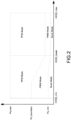
- FIG. 2 shows a schematic diagram of a first operation mode under a charging operation according to the present disclosure.
- FIG. 2 shows the method of integrating the PWM mode (pulse-width modulation mode), the PFM mode (pulse-frequency modulation mode), and the burst mode.
- the LLC resonant converter charges the battery in a step-down (buck) conversion mode (when the input voltage is greater than the battery voltage); or the LLC resonant converter charges the battery in a step-up (boost) conversion mode (when the battery is gradually fully charged and the battery voltage gradually increases so that the input voltage is lower than the battery voltage).
- buck step-down
- boost step-up
- the duty cycle is adjusted.
- the LLC resonant converter operates at the PWM mode by adjusting the duty cycle between the maximum duty cycle (50%) and minimum duty cycle.
- the purpose of adding the PWM mode between the PFM mode and the burst mode is that under the applications of wide-range input voltage or output voltage, although the maximum duty cycle of 50% is fixed/maintained (in the PFM mode) and the maximum frequency is fixed/maintained (in the burst mode), it will still cause ripples in the output voltage.
- the duty cycle is no longer fixed to the maximum duty cycle of 50%, but the burst mode is used at the minimum duty cycle of less than 50% (for example, 10%) so that the ripple of the output voltage can be smaller in the burst mode, and even under lighter load, the effect of reducing the ripple of the output voltage can also be achieved.
- the abscissa represents the output voltage (HVDC side voltage), and the ordinate represents the output power (i.e., corresponding to the output current).
- HVDC_min the minimum voltage
- the resonant converter usually operates in the burst mode when the output current is smaller and the output power is smaller (below Po_min).
- Po_boundary a boundary power
- the output power required for the resonant converter to leave the burst mode and enter the PWM mode does not need to be too large. In other words, it does not require too much output power to make the resonant converter leave the burst mode and enter the PWM mode. Since the range of the PWM mode is relatively small, only a little more output power is needed to leave the PWM mode and enter the PFM mode.
- the PWM mode is introduced to achieve the effect of voltage ripple reduction cannot be solved by only entering the burst mode in the PFM mode, especially in the very light load operation.
- the PFM mode by integrating the PFM mode, the PWM mode, and the burst mode, it can solve the situation that the voltage gain is still too high under the condition of low voltage output or high voltage input so that the output voltage will not fluctuate too much due to entering the burst mode, and a more stable output effect can be achieved.
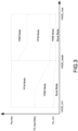
- FIG. 3 is a schematic diagram of a second operation mode under the charging operation according to the present disclosure.
- a PSM mode phase-shift modulation mode
- the secondary side is the synchronous rectification side.
- the original open-loop injection phase shifting method may be changed to a closed-loop control method so that the phase shift on the synchronous rectification side with a fixed frequency and duty cycle is preformed to increase the voltage conversion ratio when the frequency gradually decreases to the lowest frequency due to insufficient voltage gain.
- phase-shift modulation mode control of delay control under the closed loop and low frequency it only needs to determine the lowest frequency and limit the maximum phase shift to achieve the convenience of adjusting parameters. Accordingly, through the phase-shift modulation mode control of delay control under the closed loop and low frequency, it can solve the problem that cannot be achieved by only PFM mode operation only higher voltage gain is required at higher output voltage or heavier loading.
- FIG. 6 shows a schematic diagram of control signals of active switches at a primary side and a secondary side under the charging operation according to the present disclosure.
- the duty cycle is controlled between the minimum value (minimum duty cycle) and the maximum value (maximum duty cycle), and from the duty cycle of the minimum value shown by the solid lines, it can be increased to the duty cycle of the maximum value shown by the dotted lines.
- the duty cycle may be increased from the minimum value to the maximum value, and then even enter the PFM mode (i.e., the normal operation mode).
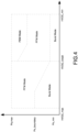
- FIG. 4 shows a schematic diagram of a first operation mode under a discharging operation according to the present disclosure.
- the delay time control is started so that the control of the resonant converter is in the PSM mode.
- the purpose of delay control is implemented through the phase shift of the switching signal to stabilize (regulate) the output voltage.
- the delay time may be controlled by shifting the switching signal on the secondary side (that is, the VBUS side) to make the transformer to be short-circuit so that the resonant energy is forced to increase, thereby increasing the voltage gain and maintaining stability of the output voltage.
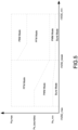
- FIG. 5 shows a schematic diagram of a second operation mode under the discharging operation according to the present disclosure.
- a PWM mode phase-width modulation mode
- the operation modes may be adjusted/switched. For example, under the light load and low input voltage, it may operate in the burst mode or the PWM mode. When the load becomes heavier or the input voltage decreases, it will be adjusted/switched to the PFM mode. Alternatively, when the load further increases or the input voltage further decreases, and the frequency is at the lowest frequency, it will be adjusted/switched to the PSM mode. Therefore, the voltage gain can be increased to control the output voltage to maintain stability.
- FIG. 7 shows a schematic diagram of control signals of active switches at the primary side and the secondary side under the discharging operation according to the present disclosure.
- the input voltage is insufficient or the output load is too large, which will make the resonant converter unable to supply the voltage required by the inverter. Therefore, the output voltage can be maintained at the voltage required by the inverter by the phase shift control.
- the primary-side switches i.e., HVDC_A to HVDC_D
- the secondary-side switches i.e., VBUS_A to VBUS_D
- the switch A i.e., VBUS_A
- the switch C i.e., VBUS_C
- the switch B may be phase-shifted so that the conduction time of the switch B and the switch D (i.e., VBUS_D) overlap the conduction time to achieve short-circuit of the transformer, thereby increasing the voltage gain to stably maintain the output voltage.
- the operation of the PSM mode in the charging mode is as described in this paragraph, and the phase shift is also performed on the secondary-side switches (that is, the switches HVDC_A and HVDC_B on the synchronous rectification side) to increase the voltage gain.
- FIG. 8 shows a flowchart of a hybrid mode control method under the first operation mode according to the present disclosure.
- This hybrid mode control method is used to control the charging or discharging of the LLC resonant converter, and the method includes steps of: first, controlling the LLC resonant converter to operate in a burst mode regardless of charging control or discharging control when determining that an output of the LLC resonant converter is in a light load (S 11, S21).
- step S10 in FIG. 9 corresponds to step S 11 in FIG. 8
- step S20 in FIG. 9 corresponds to step S12 in FIG. 8
- step S30 in FIG. 9 corresponds to step S13 in FIG. 8 .
- the LLC resonant converter is controlled to operate in a PSM mode (S40).
- step S10 in FIG. 9 corresponds to step S21 in FIG.
- step S30 in FIG. 9 corresponds to step S22 in FIG. 8
- step S40 in FIG. 9 corresponds to step S23 in FIG. 8 .
- the LLC resonant converter is controlled to operate in the PWM mode (S20). Therefore, as shown in FIG.
- the LLC resonant converter regardless of whether the LLC resonant converter is in the charging control or the discharging control, it can be operated in the hybrid mode, including the burst mode, the PWM (pulse-width modulation) mode, the PFM (pulse-frequency modulation) mode, and the PSM (phase-shift modulation) mode.
- the hybrid mode including the burst mode, the PWM (pulse-width modulation) mode, the PFM (pulse-frequency modulation) mode, and the PSM (phase-shift modulation) mode.
Landscapes
- Engineering & Computer Science (AREA)
- Power Engineering (AREA)
- Transportation (AREA)
- Mechanical Engineering (AREA)
- Dc-Dc Converters (AREA)
Applications Claiming Priority (1)
| Application Number | Priority Date | Filing Date | Title |
|---|---|---|---|
| CN202211570026.0A CN118163643A (zh) | 2022-12-08 | 2022-12-08 | 混合模式控制方法 |
Publications (1)
| Publication Number | Publication Date |
|---|---|
| EP4383541A1 true EP4383541A1 (de) | 2024-06-12 |
Family
ID=86332049
Family Applications (1)
| Application Number | Title | Priority Date | Filing Date |
|---|---|---|---|
| EP23172844.5A Pending EP4383541A1 (de) | 2022-12-08 | 2023-05-11 | Hybridmodus-steuerverfahren |
Country Status (4)
| Country | Link |
|---|---|
| US (1) | US20240195281A1 (de) |
| EP (1) | EP4383541A1 (de) |
| JP (1) | JP7796712B2 (de) |
| CN (1) | CN118163643A (de) |
Families Citing this family (1)
| Publication number | Priority date | Publication date | Assignee | Title |
|---|---|---|---|---|
| CN119966243A (zh) * | 2025-01-10 | 2025-05-09 | 广州金升阳科技有限公司 | 一种谐振变换器的控制方法、控制装置及开关电源 |
Citations (2)
| Publication number | Priority date | Publication date | Assignee | Title |
|---|---|---|---|---|
| CN112117908A (zh) * | 2020-08-11 | 2020-12-22 | 华中科技大学 | 双有源桥串联谐振变换器电路的变频移相调制装置及方法 |
| TWI752891B (zh) * | 2021-06-25 | 2022-01-11 | 台達電子工業股份有限公司 | Llc諧振轉換器及其控制方法 |
Family Cites Families (10)
| Publication number | Priority date | Publication date | Assignee | Title |
|---|---|---|---|---|
| JP5691137B2 (ja) | 2008-05-14 | 2015-04-01 | 富士電機株式会社 | スイッチング電源 |
| JP5326605B2 (ja) | 2009-01-29 | 2013-10-30 | 富士電機株式会社 | 電力変換装置 |
| JP5560664B2 (ja) | 2009-11-05 | 2014-07-30 | 富士電機株式会社 | 直流−直流変換回路の制御方法 |
| US9379617B2 (en) | 2012-02-03 | 2016-06-28 | Fuji Electric Co., Ltd. | Resonant DC-DC converter control device |
| JP5995139B2 (ja) | 2012-10-12 | 2016-09-21 | 富士電機株式会社 | 双方向dc/dcコンバータ |
| US9812977B2 (en) * | 2015-04-01 | 2017-11-07 | Futurewei Technologies, Inc. | Resonant converters with an improved voltage regulation range |
| JP6502158B2 (ja) | 2015-04-24 | 2019-04-17 | ローム株式会社 | スイッチング電源装置 |
| DE112018004240T5 (de) | 2018-12-17 | 2021-04-08 | Fuji Electric Co., Ltd. | Dc-dc-wandler |
| JP7541298B2 (ja) | 2021-01-13 | 2024-08-28 | 富士電機株式会社 | 電力変換装置、電力変換装置の制御装置、および、電力変換制御方法 |
| US11799382B2 (en) * | 2021-03-03 | 2023-10-24 | Semiconductor Components Industries, Llc | Resonant converter with dual-mode control |
-
2022
- 2022-12-08 CN CN202211570026.0A patent/CN118163643A/zh active Pending
-
2023
- 2023-05-11 EP EP23172844.5A patent/EP4383541A1/de active Pending
- 2023-05-12 US US18/316,453 patent/US20240195281A1/en active Pending
- 2023-11-07 JP JP2023190029A patent/JP7796712B2/ja active Active
Patent Citations (2)
| Publication number | Priority date | Publication date | Assignee | Title |
|---|---|---|---|---|
| CN112117908A (zh) * | 2020-08-11 | 2020-12-22 | 华中科技大学 | 双有源桥串联谐振变换器电路的变频移相调制装置及方法 |
| TWI752891B (zh) * | 2021-06-25 | 2022-01-11 | 台達電子工業股份有限公司 | Llc諧振轉換器及其控制方法 |
Non-Patent Citations (1)
| Title |
|---|
| LUO SENWEN ET AL: "Research on Hybrid Modulation Strategy of Bidirectional LLC Resonant Converter in Distributed Energy Storage System", 2022 IEEE 3RD CHINA INTERNATIONAL YOUTH CONFERENCE ON ELECTRICAL ENGINEERING (CIYCEE), IEEE, 3 November 2022 (2022-11-03), pages 1 - 6, XP034238813, DOI: 10.1109/CIYCEE55749.2022.9958990 * |
Also Published As
| Publication number | Publication date |
|---|---|
| JP7796712B2 (ja) | 2026-01-09 |
| US20240195281A1 (en) | 2024-06-13 |
| CN118163643A (zh) | 2024-06-11 |
| JP2024083249A (ja) | 2024-06-20 |
Similar Documents
| Publication | Publication Date | Title |
|---|---|---|
| CN108933526B (zh) | 宽输入宽输出高效隔离型dc-dc转换器电池充电器 | |
| US10097077B2 (en) | Control method for improving dynamic response of switch power | |
| EP2274813B1 (de) | Stromumrichtersystem, das über einen bereich von lastbedingungen effizient arbeitet | |
| US20160181925A1 (en) | Bidirectional dc-dc converter | |
| JP2012175801A (ja) | 蓄電システム | |
| US8830701B2 (en) | DC-DC converter | |
| Itoh et al. | A new approach for high efficiency buck-boost DC/DC converters using series compensation | |
| EP4383541A1 (de) | Hybridmodus-steuerverfahren | |
| JP3191097B2 (ja) | 無停電電源装置及びその充電制御方法 | |
| Kinoshita et al. | Wide-range voltage gain and high-efficiency of isolated LLC converter using six-switch and two asymmetric transformers | |
| Naresh | A new configuration for enhanced integration of a battery–ultracapacitor system | |
| AU2022418485B2 (en) | On-board charger, dcdc converter and control method | |
| US20120236608A1 (en) | Flux Converter with Power Factor Correction | |
| TWI816617B (zh) | 混合模式控制方法 | |
| Yoon et al. | A frequency controlled bi-directional synchronous rectifier converter for HEV using super-capacitor | |
| Kumar et al. | Light-load and cross-load control of integrated OBC and APM for electric vehicle applications | |
| CN115706530B (zh) | 一种大功率脉冲电源控制系统及控制方法 | |
| Prabhakar et al. | Design Methodology to Improve Efficiency of Semi-dual Active Bridge Converter | |
| JP2023007755A (ja) | Dc/dcコンバータ、電力変換システム | |
| CN120016833B (zh) | 稳压电路控制方法、控制装置及电源设备 | |
| Leuchter | Bi-directional DC-DC converters for battery buffers with supercapacitor | |
| Lin et al. | Wide voltage range DC/DC converter for railway auxiliary power units | |
| US20230118346A1 (en) | Method of Power Factor Correction Burst Mode Load Measurement and Control | |
| US20260074553A1 (en) | Uninterruptible power supply system | |
| CN112714999A (zh) | 一种供电控制方法和装置 |
Legal Events
| Date | Code | Title | Description |
|---|---|---|---|
| PUAI | Public reference made under article 153(3) epc to a published international application that has entered the european phase |
Free format text: ORIGINAL CODE: 0009012 |
|
| STAA | Information on the status of an ep patent application or granted ep patent |
Free format text: STATUS: REQUEST FOR EXAMINATION WAS MADE |
|
| 17P | Request for examination filed |
Effective date: 20240131 |
|
| AK | Designated contracting states |
Kind code of ref document: A1 Designated state(s): AL AT BE BG CH CY CZ DE DK EE ES FI FR GB GR HR HU IE IS IT LI LT LU LV MC ME MK MT NL NO PL PT RO RS SE SI SK SM TR |