EP4383427A1 - Assembly system and assembly method of battery module assembly - Google Patents
Assembly system and assembly method of battery module assembly Download PDFInfo
- Publication number
- EP4383427A1 EP4383427A1 EP22904603.2A EP22904603A EP4383427A1 EP 4383427 A1 EP4383427 A1 EP 4383427A1 EP 22904603 A EP22904603 A EP 22904603A EP 4383427 A1 EP4383427 A1 EP 4383427A1
- Authority
- EP
- European Patent Office
- Prior art keywords
- battery cells
- battery module
- assembling
- assembly
- rows
- Prior art date
- Legal status (The legal status is an assumption and is not a legal conclusion. Google has not performed a legal analysis and makes no representation as to the accuracy of the status listed.)
- Pending
Links
Images


Classifications
-
- H—ELECTRICITY
- H01—ELECTRIC ELEMENTS
- H01M—PROCESSES OR MEANS, e.g. BATTERIES, FOR THE DIRECT CONVERSION OF CHEMICAL ENERGY INTO ELECTRICAL ENERGY
- H01M10/00—Secondary cells; Manufacture thereof
- H01M10/05—Accumulators with non-aqueous electrolyte
- H01M10/052—Li-accumulators
-
- H—ELECTRICITY
- H01—ELECTRIC ELEMENTS
- H01M—PROCESSES OR MEANS, e.g. BATTERIES, FOR THE DIRECT CONVERSION OF CHEMICAL ENERGY INTO ELECTRICAL ENERGY
- H01M10/00—Secondary cells; Manufacture thereof
- H01M10/04—Construction or manufacture in general
- H01M10/0404—Machines for assembling batteries
-
- H—ELECTRICITY
- H01—ELECTRIC ELEMENTS
- H01M—PROCESSES OR MEANS, e.g. BATTERIES, FOR THE DIRECT CONVERSION OF CHEMICAL ENERGY INTO ELECTRICAL ENERGY
- H01M10/00—Secondary cells; Manufacture thereof
- H01M10/04—Construction or manufacture in general
- H01M10/0481—Compression means other than compression means for stacks of electrodes and separators
-
- H—ELECTRICITY
- H01—ELECTRIC ELEMENTS
- H01M—PROCESSES OR MEANS, e.g. BATTERIES, FOR THE DIRECT CONVERSION OF CHEMICAL ENERGY INTO ELECTRICAL ENERGY
- H01M10/00—Secondary cells; Manufacture thereof
- H01M10/60—Heating or cooling; Temperature control
- H01M10/61—Types of temperature control
- H01M10/613—Cooling or keeping cold
-
- H—ELECTRICITY
- H01—ELECTRIC ELEMENTS
- H01M—PROCESSES OR MEANS, e.g. BATTERIES, FOR THE DIRECT CONVERSION OF CHEMICAL ENERGY INTO ELECTRICAL ENERGY
- H01M10/00—Secondary cells; Manufacture thereof
- H01M10/60—Heating or cooling; Temperature control
- H01M10/62—Heating or cooling; Temperature control specially adapted for specific applications
- H01M10/625—Vehicles
-
- H—ELECTRICITY
- H01—ELECTRIC ELEMENTS
- H01M—PROCESSES OR MEANS, e.g. BATTERIES, FOR THE DIRECT CONVERSION OF CHEMICAL ENERGY INTO ELECTRICAL ENERGY
- H01M10/00—Secondary cells; Manufacture thereof
- H01M10/60—Heating or cooling; Temperature control
- H01M10/65—Means for temperature control structurally associated with the cells
- H01M10/655—Solid structures for heat exchange or heat conduction
- H01M10/6554—Rods or plates
- H01M10/6555—Rods or plates arranged between the cells
-
- H—ELECTRICITY
- H01—ELECTRIC ELEMENTS
- H01M—PROCESSES OR MEANS, e.g. BATTERIES, FOR THE DIRECT CONVERSION OF CHEMICAL ENERGY INTO ELECTRICAL ENERGY
- H01M10/00—Secondary cells; Manufacture thereof
- H01M10/60—Heating or cooling; Temperature control
- H01M10/65—Means for temperature control structurally associated with the cells
- H01M10/655—Solid structures for heat exchange or heat conduction
- H01M10/6556—Solid parts with flow channel passages or pipes for heat exchange
- H01M10/6557—Solid parts with flow channel passages or pipes for heat exchange arranged between the cells
-
- H—ELECTRICITY
- H01—ELECTRIC ELEMENTS
- H01M—PROCESSES OR MEANS, e.g. BATTERIES, FOR THE DIRECT CONVERSION OF CHEMICAL ENERGY INTO ELECTRICAL ENERGY
- H01M50/00—Constructional details or processes of manufacture of the non-active parts of electrochemical cells other than fuel cells, e.g. hybrid cells
- H01M50/20—Mountings; Secondary casings or frames; Racks, modules or packs; Suspension devices; Shock absorbers; Transport or carrying devices; Holders
- H01M50/262—Mountings; Secondary casings or frames; Racks, modules or packs; Suspension devices; Shock absorbers; Transport or carrying devices; Holders with fastening means, e.g. locks
- H01M50/264—Mountings; Secondary casings or frames; Racks, modules or packs; Suspension devices; Shock absorbers; Transport or carrying devices; Holders with fastening means, e.g. locks for cells or batteries, e.g. straps, tie rods or peripheral frames
-
- H—ELECTRICITY
- H01—ELECTRIC ELEMENTS
- H01M—PROCESSES OR MEANS, e.g. BATTERIES, FOR THE DIRECT CONVERSION OF CHEMICAL ENERGY INTO ELECTRICAL ENERGY
- H01M10/00—Secondary cells; Manufacture thereof
- H01M10/60—Heating or cooling; Temperature control
- H01M10/64—Heating or cooling; Temperature control characterised by the shape of the cells
- H01M10/643—Cylindrical cells
-
- H—ELECTRICITY
- H01—ELECTRIC ELEMENTS
- H01M—PROCESSES OR MEANS, e.g. BATTERIES, FOR THE DIRECT CONVERSION OF CHEMICAL ENERGY INTO ELECTRICAL ENERGY
- H01M2220/00—Batteries for particular applications
- H01M2220/20—Batteries in motive systems, e.g. vehicle, ship, plane
-
- H—ELECTRICITY
- H01—ELECTRIC ELEMENTS
- H01M—PROCESSES OR MEANS, e.g. BATTERIES, FOR THE DIRECT CONVERSION OF CHEMICAL ENERGY INTO ELECTRICAL ENERGY
- H01M50/00—Constructional details or processes of manufacture of the non-active parts of electrochemical cells other than fuel cells, e.g. hybrid cells
- H01M50/20—Mountings; Secondary casings or frames; Racks, modules or packs; Suspension devices; Shock absorbers; Transport or carrying devices; Holders
- H01M50/204—Racks, modules or packs for multiple batteries or multiple cells
- H01M50/207—Racks, modules or packs for multiple batteries or multiple cells characterised by their shape
- H01M50/213—Racks, modules or packs for multiple batteries or multiple cells characterised by their shape adapted for cells having curved cross-section, e.g. round or elliptic
-
- Y—GENERAL TAGGING OF NEW TECHNOLOGICAL DEVELOPMENTS; GENERAL TAGGING OF CROSS-SECTIONAL TECHNOLOGIES SPANNING OVER SEVERAL SECTIONS OF THE IPC; TECHNICAL SUBJECTS COVERED BY FORMER USPC CROSS-REFERENCE ART COLLECTIONS [XRACs] AND DIGESTS
- Y02—TECHNOLOGIES OR APPLICATIONS FOR MITIGATION OR ADAPTATION AGAINST CLIMATE CHANGE
- Y02E—REDUCTION OF GREENHOUSE GAS [GHG] EMISSIONS, RELATED TO ENERGY GENERATION, TRANSMISSION OR DISTRIBUTION
- Y02E60/00—Enabling technologies; Technologies with a potential or indirect contribution to GHG emissions mitigation
- Y02E60/10—Energy storage using batteries
-
- Y—GENERAL TAGGING OF NEW TECHNOLOGICAL DEVELOPMENTS; GENERAL TAGGING OF CROSS-SECTIONAL TECHNOLOGIES SPANNING OVER SEVERAL SECTIONS OF THE IPC; TECHNICAL SUBJECTS COVERED BY FORMER USPC CROSS-REFERENCE ART COLLECTIONS [XRACs] AND DIGESTS
- Y02—TECHNOLOGIES OR APPLICATIONS FOR MITIGATION OR ADAPTATION AGAINST CLIMATE CHANGE
- Y02P—CLIMATE CHANGE MITIGATION TECHNOLOGIES IN THE PRODUCTION OR PROCESSING OF GOODS
- Y02P70/00—Climate change mitigation technologies in the production process for final industrial or consumer products
- Y02P70/50—Manufacturing or production processes characterised by the final manufactured product
Definitions
- the present disclosure relates to an assembling system and method for a battery module assembly.
- Secondary batteries have high applicability according to product groups and electrical characteristics such as high energy density, and thus, are commonly applied not only to mobile devices but also to electric vehicles (EVs) or hybrid vehicles (HEVs) driven by electric power sources. Because secondary batteries may radically reduce the use of fossil fuel and do not generate any by-products that come with energy consumption, the secondary batteries are gaining attention as a new alternative energy source for improving eco-friendliness and energy efficiency.
- EVs electric vehicles
- HEVs hybrid vehicles
- Types of secondary batteries that are currently widely used include lithium-ion batteries, lithium polymer batteries, nickel cadmium batteries, nickel hydride batteries, and nickel zinc batteries.
- An operating voltage of a unit secondary battery cell ranges from about 2.5 V to about 4.5 V. Accordingly, when a higher output voltage is required, a battery pack may be configured by connecting a plurality of battery cells in series. Also, a battery pack may be configured by connecting a plurality of battery cells in parallel according to charge/discharge capacity required for the battery pack. Accordingly, the number of battery cells included in a battery pack may be set in various ways according to a required output voltage or charge/discharge capacity.
- a method of first configuring a battery module including at least one battery cell and adding other elements by using the at least one battery module to configure a battery pack is general.
- a conventional battery module is generally configured to include a plurality of battery cells and a cell frame accommodating the plurality of battery cells.
- a conventional cell frame is generally composed of an assembly of a plurality of plates such as a front plate, a rear plate, a side plate, a lower plate, and an upper plate to accommodate the plurality of battery cells and secure rigidity.
- the conventional battery module is disadvantageous in terms of cost competitiveness and manufacturing efficiency since manufacturing cost increases and the assembly process is complicated due to the characteristics of a cell frame structure composed of an assembly of a plurality of plates.
- the conventional battery module is disadvantageous in terms of energy density since the size of the entire battery module is increased according to the cell frame structure composed of an assembly of a plurality of plates.
- the present disclosure is directed to providing an assembling system and method for a battery module assembly, which may implement a frameless structure.
- the present disclosure is directed to providing an assembling system and method for a battery module assembly, which may reduce manufacturing cost and minimizing an assembly space.
- an assembling system for a battery module assembly comprising: a first transfer device configured to transfer a plurality of battery cells in two rows; an aligning device configured to assemble a cell assembly by aligning a cooling unit between the two rows of battery cells transferred by the first transfer device; and a second transfer device configured to transfer the cell assembly assembled by the aligning device toward a structure assembling device for assembly with a side structure unit that covers the battery cells.
- the first transfer device may include an upper conveyor configured to transfer the two rows of battery cells; and a lower conveyor configured to guide the two rows of battery cells to the aligning device
- the first transfer device may include a lift unit configured to be movable up and down between the upper conveyor and the lower conveyor and transfer the two rows of battery cells of the upper conveyor to the lower conveyor.
- the aligning device may mutually bond the cooling unit between the two rows of battery cells to form the cell assembly.
- the second transfer device may be provided to be movable along the ceiling of the assembling system for a battery module assembly.
- the second transfer device may cure the cell assembly at room temperature during the transfer.
- the second transfer device may lift and transfer the cell assembly without changing a direction of the cell assembly.
- the assembling system for a battery module assembly may further comprise the structure assembling device configured to form the battery module assembly by arranging a plurality of side structure units between the battery cells of at least one cell assembly transferred by the second transfer device.
- the structure assembling device may mutually bond the plurality of side structure units and the at least one cell assembly.
- an assembling method for a battery module assembly comprising: transferring a plurality of battery cells in two rows; assembling a cell assembly by aligning a cooling unit between the battery cells transferred in two rows; transferring the cell assembly toward a side structure unit that covers the battery cells of the cell assembly; and assembling the battery module assembly by covering the battery cells of the cell assembly with the side structure unit.
- said transferring of a plurality of battery cells in two rows may include transferring the two rows of battery cells through an upper conveyor; and transferring the two rows of battery cells of the upper conveyor to a lower conveyor for assembling the cell assembly.
- the cell assembly may be formed by mutually bonding the cooling unit arranged between the two rows of battery cells with the two rows of battery cells through an adhesive.
- the battery module assembly may be formed by mutually bonding the battery cells of the cell assembly with the side structure unit through an adhesive.
- the cell assembly may be cured at room temperature when transferred toward the side structure unit.
- the cell assembly when transferred toward the side structure unit, may be transferred toward the side structure unit along the ceiling.
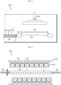
- FIG. 1 is a diagram for explaining an assembling system for a battery module assembly according to an embodiment of the present disclosure.
- the assembling system 10 for a battery module assembly may include a first transfer device 100, an aligning device 200, and a second transfer device 300.
- the first transfer device 100 may transfer a plurality of battery cells 3 in two rows.
- the first transfer device 100 may guide the plurality of battery cells 3 toward the aligning device 200 to be described later.
- the aligning device 200 may assemble a cell assembly (7, see FIG. 4 ) by aligning a cooling unit (5, see FIG. 3 ) between two rows of battery cells 3 transferred by the first transfer device 100.
- the cell assembly 7 may be formed of the battery cells 3 and the cooling unit 5.
- the second transfer device 300 may transfer the cell assembly 7 assembled by the aligning device 200 toward the structure assembling device 400 for assembly with a side structure unit (9, see FIG. 5 ) that covers the battery cells 3.
- the structure assembling device 400 described later may assemble the cell assembly 7 transferred by the second transfer device 300 with the side structure unit 9 to manufacture a battery module assembly (1, see FIG. 30 ).
- the battery module assembly (1, see FIG. 30 ) provided with a cell assembly 7 formed of the battery cells 3 and the cooling unit 5 and a side structure unit 9 assembled with the cell assembly 7 may be implemented.
- the battery module assembly 1 fixes and supports the cell assembly 7 only by the side structure unit 9, and thus it is possible to omit a conventional frame structure provided as an assembly of a plurality of plate structures such as an upper plate, a lower plate, a front plate, a rear plate, and a side plate. That is, the battery module assembly 1 according to this embodiment may be provided to have a frameless structure.
- the battery module assembly 1 is provided in one or in plurality, and by adding a component for electrical connection, etc., a battery pack may be configured and mounted on a vehicle such as an automobile or a mechanism or structure such as an energy storage system.
- the assembling system 10 may reduce manufacturing cost and simplify the assembly process compared to the conventional cell frame structure, thereby significantly improving cost competitiveness and manufacturing efficiency.
- the assembling system 10 may secure high energy density while realizing a slimmer and more compact structure compared to a conventional cell frame structure.
- the first transfer device 100 may include an upper conveyor 110 and a lower conveyor 130.
- the upper conveyor 110 may transfer the two rows of battery cells 3. To this end, two rows of conveyor belt lines for transferring the two rows of battery cells 3 may be provided in the upper conveyor 110.
- the lower conveyor 130 may guide the two rows of battery cells 3 to the aligning device 200. To this end, two rows of conveyor belt lines for transferring the two rows of battery cells 3 may be provided in the lower conveyor 130.
- the lower conveyor 130 may be disposed below the upper conveyor 110 at a predetermined distance from the upper conveyor 110.
- the entire conveyor line may be reduced compared to a structure in which a straight conveyor is arranged long.
- the assembly space may be minimized by reducing the length of the entire assembly line through the first transfer device 100. Accordingly, in this embodiment, it is possible to optimize the entire assembly space as well as to reduce the construction cost for constructing the assembling system 10.
- the first transfer device 100 may include a lift unit 150.
- the lift unit 150 may move up and down between the upper conveyor 110 and the lower conveyor 130, and may transfer the two rows of battery cells 3 of the upper conveyor 110 to the lower conveyor 130.
- the lift unit 150 may be provided to be slidable along a ceiling rail 600 provided on the ceiling of the assembling system 10. Accordingly, the lift unit 150 may be movable in both horizontal and vertical directions within the assembling system 10.
- the aligning device 200 is provided in the assembling system 10 of the battery module assembly (1, see FIG. 30 ), and may assemble two rows of battery cells 3 and the cooling unit 5 to form a cell assembly.
- the aligning device 200 may form the cell assembly 7 by mutually bonding the cooling unit 5 between the two rows of battery cells 3.
- the cell assembly 7 may be provided as an assembly of the battery cells 3 and the cooling unit 5 through the aligning device 200.
- FIG. 2 is a schematic diagram for explaining an aligning device of the assembling system for a battery module assembly of FIG. 1
- FIG. 3 is a diagram for explaining the main part of the aligning device of FIG. 2
- FIG. 4 is a schematic cross-sectional view of the aligning device of FIG. 2 .
- the aligning device 200 may include a guide jig 210, a cell spacing adjusting jig 220, and a cooling unit gripper 230.
- the guide jig 210 is for supporting the two rows of battery cells 3 and may be provided as a pair.
- the pair of guide jigs 210 may be provided to support the battery cells 3 of each row.
- the cell spacing adjusting jig 220 is connected to the pair of guide jigs 210 and may adjust the spacing of battery cells 3 in each row.
- the cell spacing adjusting jig 220 is provided as a pair and may be slidably mounted on each guide jig 210.
- the cooling unit gripper 230 may place the cooling unit 5 between the pair of guide jigs 210.
- the cooling unit grippers 230 are provided as a pair and may support both ends of the cooling unit 5.
- the aligning device 200 may adjust the spacing of the two rows of battery cells 3 by the sliding of the guide jig 210 and the cell spacing adjusting jig 220 in a state in which the two rows of battery cells 3 are placed in a standing state with the cooling unit 5 interposed therebetween.
- the pair of guide jigs 210 may be provided to be slidable along a direction toward the cooling unit gripper 230 and a direction opposite to the cooling unit gripper 226. That is, the pair of guide jigs 210 may be provided to be slidable along a direction toward the cooling unit 5 and a direction opposite to the cooling unit 5 while supporting the battery cells 3 in each row.
- the pair of guide jigs 210 may pressurize the battery cells 3 of each row through the sliding operation to bring the battery cells 3 of each row into close contact with both side surfaces of the cooling unit 5.
- the cell spacing adjusting jig 220 is provided as a pair and is slidably mounted on one side of the pair of guide jigs 210, and at least a part thereof may penetrate the pair of guide jigs 210 during the sliding to adjust the spacing of the battery cells 3 in each row while sliding between the battery cells 3 of each row.
- the pair of cell spacing adjusting jigs 220 may include an adjusting jig body 222 and a spacing adjusting portion 226, respectively.
- the adjusting jig body 222 may be slidably mounted on one side of each guide jig 210.
- the adjusting jig body 222 may be disposed to face the battery cells 3 with the guide jig 210 interposed therebetween.
- the spacing adjusting portion 226 is provided in plurality and protrudes from the adjusting jig body 222 to a predetermined length, and during the sliding, the spacing adjusting portion 226 may penetrate each guide jig 210 and slide between the battery cells 3 in each row to widen the spacing between the battery cells 3 in each row at a predetermined interval.
- the plurality of spacing adjusting portions 226 may be spaced apart from each other by a predetermined distance at equal intervals along the longitudinal direction of the adjusting jig body 222. Accordingly, according to the sliding operation of the plurality of spacing adjusting portions 226, the spacing between the battery cells 3 in each row may be adjusted at equal intervals.
- the aligning device 200 may include a cell support 240.
- the cell support 240 is provided on the pair of guide jigs 210 and may support the battery cells 3.
- the cell support 240 may guide the battery cells 3 seated on the pair of guide jigs 210 to be supported more stably.
- the cell support 240 may be provided as a magnetic member.
- the cell support 240 may be provided in plurality.
- the plurality of cell supports 240 may be provided at a position facing the battery cells 3 when the battery cells 3 are seated on the guide jig 210.
- the aligning device 200 may include an aligning gripper 250.
- the aligning gripper 250 is provided on the upper side of the pair of guide jigs 210, and may pressurize and fix the upper end of two rows of battery cells 3 disposed with the cooling unit 5 interposed therebetween.
- the aligning gripper 250 may further increase the coupling solidity in the upper part of the battery cells 3 and the cooling unit 5.
- the aligning gripper 250 may guide a subsequent transfer process of the cell assembly 7 provided with the battery cells 3 and the cooling unit 5.
- the aligning device 200 may form the cell assembly 7 by mutually aligning and bonding the cooling unit 5 between the two rows of battery cells 3.
- the second transfer device 300 may be provided to be movable along the ceiling of the assembling system 10 of the battery module assembly (1, see FIG. 30 ).
- the second transfer device 300 may be slidably mounted on the ceiling rail 600.
- the second transfer device 300 may be provided to be movable up and down in a vertical direction.
- the second transfer device 300 may also be integrated with the lift unit 150. That is, the second transfer device 300 and the lift unit 150 of the first transfer device 100 may be provided as one lifting body.
- the second transfer device 300 may cure the cell assembly 7 at room temperature during the transfer. To this end, the second transfer device 300 may be provided with components for curing the cell assembly 7 at room temperature.
- the curing process of the cell assembly 7 may be performed during the transfer of the second transfer device 300 provided on the ceiling rail 600, so it is possible to save space in the curing process and further shorten the assembly process time by reducing the takt time of the assembly process.
- the second transfer device 300 may lift and transfer the cell assembly 7 from the aligning device 200 without changing the direction of the cell assembly 7. Accordingly, in this embodiment, during the transfer, a rotation process for adjusting the insertion direction of the battery cells 3 of the cell assembly 7 is not separately required, so the process efficiency may be further increased.
- the structure assembling device 400 may form the battery module assembly 1 by arranging a plurality of side structure units 9 between the battery cells 3 of at least one cell assembly 7 transferred by the second transfer device 300.
- the structure assembling device 400 may form the battery module assembly 1 by bonding the plurality of side structure units 9 and the at least one cell assembly 7 to each other.
- the battery module assembly 1 provided with the battery cells 3, the cooling unit 5, and the side structure units 9 may be assembled through the structure assembling device 400.
- FIG. 5 is a schematic diagram for explaining a structure assembling device of the assembling system for a battery module assembly of FIG. 1 .
- the structure assembling device 400 may include an assembling base 410 and a sliding jig 430.
- the assembling base 410 may guide alignment of the at least one cell assembly 7 and the at least one side structure unit 9 to form the battery module assembly 1.
- the sliding jig 430 is slidably provided on the assembling base 410 and may bring the at least one cell assembly 7 and the at least one side structure unit 9 into close contact with each other through the sliding.
- FIG. 6 is a schematic diagram for explaining a pre-working device of the assembling system for a battery module assembly of FIG. 1 .
- the pre-working device 500 may perform the preprocessing process of the cooling unit 5 and the side structure unit 9.
- the pre-working device 500 may include a plasma processing unit 510, an adhesive processing unit 530, and a direction changing unit 550.
- the plasma processing unit 510 is for treating plasma P toward the cooling unit 5, and may be slidably provided along the longitudinal direction of the cooling unit 5.
- the adhesive processing unit 530 is for applying adhesive G to the cooling unit 5 and the side structure unit 9, and may be slidably provided along the longitudinal direction of the cooling unit 5 and the side structure unit 9.
- the direction changing unit 550 may guide the treatment of the plasma P and the application of the adhesive G and support the cooling unit 5 or the side structure unit 9 during the treatment of the plasma P or the application of the adhesive G.
- the direction changing unit 550 may change the direction of the cooling unit 5 or the side structure unit 9 so that the treatment of the plasma P or the application of the adhesive G may be performed to both side surfaces of the cooling unit 5 or the side structure unit 9.
- the assembling system 10 may include the ceiling rail 600.
- the ceiling rail 600 is provided on the ceiling of the assembling system 10 and may guide the sliding operation of the lift unit 150 of the first transfer device 100 and the second transfer device 300.
- the ceiling rail 600 is provided on the ceiling of the system to guide the transfer, etc., space utilization of the entire system may be maximized and space for system equipment construction may be saved.
- FIGS. 7 and 8 are diagrams for explaining the operation of a first transfer device of the assembling system for a battery module assembly of FIG. 1 .
- the lift unit 150 of the first transfer device 100 may transfer the two rows of battery cells 3 on the first conveyor 110 toward the second conveyor 130.
- the lift unit 150 may lift the two rows of battery cells 3 on the first conveyor 110 through adsorption, etc., move them along the ceiling rail 600 toward the second conveyor 130 by a predetermined distance, and then descend to place them on the second conveyor 130.
- FIGS. 9 to 13 are diagrams for explaining the operation of the aligning device of the assembling system for a battery module assembly of FIG. 1 .
- the aligning device 200 may arrange the cooling unit 5 between the two rows of battery cells 3 transferred from the first transfer device 100 to bring the two rows of battery cells 3 and the cooling unit 5 into close contact, thereby forming the cell assembly 7.
- the pair of guide jigs 210 may pressurize the battery cells 3 of each row to come into close contact with the cooling unit 5.
- the pair of cell spacing adjusting jigs 220 may adjust the spacing between the battery cells 3 in each row while sliding through the guide jig 210.
- the battery cells 3 and the cooling unit 5 may be bonded to each other when they are in close contact.
- the cell assembly 7 may be formed by mutually bonding the battery cells 3 and the cooling unit 5.
- the pair of guide jigs 210 may slide in a direction away from the cell assembly 7, and the aligning gripper 250 may press both sides of the upper end of the cell assembly 7. Accordingly, the coupling strength between the battery cells 3 and the cooling unit 5 at the upper end of the cell assembly 7 may be further increased. Then, the aligning gripper 250 may lift the cell assembly 7 and guide the cell assembly 7 to a subsequent process.
- FIGS. 14 to 16 are diagrams for explaining the operation of an aligning device according to another embodiment of the assembling system for a battery module assembly of FIG. 1 .
- the aligning device 200 is similar to the aligning device 205 of the previous embodiment, redundant description of components identical as or similar to those of the previous embodiment will be omitted, and hereinafter, the focus will be on differences from the previous embodiment.
- the aligning device 205 may include a pair of guide jigs 215 provided to be tiltable at a predetermined angle with the cooling unit gripper 230 interposed therebetween.
- the pair of guide jigs 215 may be arranged to be inclined at a predetermined angle before the two rows of battery cells 3 and the cooling unit 5 come into close contact, so that the battery cells 3 in each row may be more stably supported.
- the pair of guide jigs 215 are provided to implement both sliding and tilting operations, the two rows of battery cells 3 may be more stably supported during the alignment or pressing operation.
- FIGS. 17 and 18 are diagrams for explaining the operation of a second transfer device of the assembling system for a battery module assembly of FIG. 1 .
- the second transfer device 300 may lift the cell assembly 7 from the aligning device 200 and transfer it toward the structure assembling device 400.
- the second transfer device 300 may cure the cell assembly 7 at room temperature to further increase the bonding strength of the cell assembly 7.
- the cell assembly 7 may be cured, so that assembly fixation efficiency may be further improved.
- FIGS. 19 to 23 are diagrams for explaining the pre-processing operation of a cooling unit through the pre-working device of the assembling system for a battery module assembly of FIG. 1 .
- the pre-working device 500 may perform a preprocessing process before transferring the cooling unit 5 toward the aligning device 200.
- the plasma processing unit 510 of the pre-working device 500 may treat plasma P on one side surface of both side surfaces of the cooling unit 5 while sliding along the longitudinal direction of the cooling unit 5.
- the adhesive processing unit 530 of the pre-working device 500 may apply the adhesive G to one side surface of both side surfaces of the cooling unit 5 while sliding along the longitudinal direction of the cooling unit 5.
- the direction changing unit 550 may change the direction of the cooling unit 5.
- the plasma processing unit 510 of the pre-working device 500 may treat plasma P on the other side surface of both side surfaces of the cooling unit 5 while sliding along the longitudinal direction of the cooling unit 5.
- the adhesive processing unit 530 of the pre-working device 500 may apply the adhesive G to the other side surface of both side surfaces of the cooling unit 5 while sliding along the longitudinal direction of the cooling unit 5.
- the pre-working device 500 may transfer the cooling unit 5, where the treatment of the plasma P and the application of the adhesive G are performed on both side surfaces, toward the aligning device 200.
- FIGS. 24 to 26 are diagrams for explaining the pre-processing operation of a side structure unit through the pre-working device of the assembling system for a battery module assembly of FIG. 1 .
- the pre-working device 500 may perform a preprocessing process before transferring the side structure unit 9 toward the structure assembling device 400.
- the adhesive processing unit 530 of the pre-working device 500 may apply the adhesive G to one side surface of both side surfaces of the side structure unit 9 while sliding along the longitudinal direction of the side structure unit 9.
- the direction changing unit 550 may change the direction of the side structure unit 9.
- the adhesive processing unit 530 of the pre-working device 500 may apply the adhesive G to the other side surface of both side surfaces of the side structure unit 9 while sliding along the longitudinal direction of the side structure unit 9.
- the pre-working device 500 may transfer the side structure unit 9, where the adhesive G is applied to both side surfaces, toward the structure assembling device 400.
- FIGS. 27 to 29 are diagrams for explaining the operation of a structure assembling device of the assembling system for a battery module assembly of FIG. 1 .
- the assembling base 410 of the structure assembling device 400 may arrange the side structure unit 9 and the cell assembly 7 to be alternately disposed.
- the sliding jig 430 may bring the side structure units 9 into close contact with the cell assembly 7 while sliding along the assembling base 410. Accordingly, the side structure unit 9 and the cell assembly 7 may be bonded to each other while closely contacting each other to form the battery module assembly 1.
- the assembly method of the battery module assembly includes the steps of transferring a plurality of battery cells 3 in two rows, arranging a cooling unit 5 between the battery cells 3 transferred in two rows to assemble a cell assembly 7, transferring the cell assembly 7 toward the side structure unit 9 that covers the battery cells 3 of the cell assembly 7, and covering the battery cells 3 of the cell assembly 7 with the side structure unit 9 to assemble the battery module assembly 1.
- the step of transferring the plurality of battery cells 3 in two rows includes the steps of transferring the two rows of battery cells 3 through the upper conveyor 110 and transferring the two rows of battery cells 3 of the upper conveyor 110 to the lower conveyor 130 for assembling the cell assembly 7.
- the cell assembly 7 may be formed by mutually bonding the cooling unit 5 aligned between the two rows of battery cells 3 to the two rows of battery cells 3 through adhesive G.
- the battery module assembly 1 may be formed by mutually bonding the battery cells 3 of the cell assembly 7 and the side structure unit 9 through adhesive G.
- the cell assembly 7 may be cured at room temperature when transferred to the side structure unit 9. Accordingly, the battery cells 3 and the cooling unit 5 of the cell assembly 7 may be more firmly coupled to each other prior to being assembled with the side structure unit 9. In addition, when the cell assembly is transferred toward the side structure unit 9, it may be transferred toward the side structure unit 9 along the ceiling.
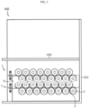
- FIG. 30 is a diagram for explaining a battery module assembly assembled through the assembling system for a battery module assembly of FIG. 1 .
- the battery module assembly 1 may include a plurality of cell assembly 7 having a cooling unit 5 between the battery cells 3, and a plurality of side structure units 9 provided between the plurality of cell assemblies 7 and forming both outermost side surfaces of the battery module assembly 1.
- the battery module assembly 1 is formed only of the plurality of cell assemblies 7 and the plurality of side structure units 9, a frameless structure may be implemented without the same conventional frame structure.
- the battery module assembly 1 manufactured through the assembling system 10 according to this embodiment is provided as a frameless structure, it may be slimmer than a conventional frame structure and may secure a relatively high energy density.
- the present disclosure is directed to providing an assembling system 10 and method for a battery module assembly 1, which may implement a frameless structure.
- the present disclosure is directed to providing an assembling system 10 and method for a battery module assembly 1, which may reduce manufacturing cost and minimizing an assembly space.
Landscapes
- Chemical & Material Sciences (AREA)
- Chemical Kinetics & Catalysis (AREA)
- Electrochemistry (AREA)
- General Chemical & Material Sciences (AREA)
- Engineering & Computer Science (AREA)
- Manufacturing & Machinery (AREA)
- Battery Mounting, Suspending (AREA)
- Secondary Cells (AREA)
Abstract
Description
- The present disclosure relates to an assembling system and method for a battery module assembly.
- The present application claims priority to
Korean Patent Application No. 10-2021-0174261 filed on December 7, 2021 Korean Patent Application No. 10-2021-0189013 filed on December 27, 2021 - Secondary batteries have high applicability according to product groups and electrical characteristics such as high energy density, and thus, are commonly applied not only to mobile devices but also to electric vehicles (EVs) or hybrid vehicles (HEVs) driven by electric power sources. Because secondary batteries may radically reduce the use of fossil fuel and do not generate any by-products that come with energy consumption, the secondary batteries are gaining attention as a new alternative energy source for improving eco-friendliness and energy efficiency.
- Types of secondary batteries that are currently widely used include lithium-ion batteries, lithium polymer batteries, nickel cadmium batteries, nickel hydride batteries, and nickel zinc batteries. An operating voltage of a unit secondary battery cell, that is, a unit battery cell, ranges from about 2.5 V to about 4.5 V. Accordingly, when a higher output voltage is required, a battery pack may be configured by connecting a plurality of battery cells in series. Also, a battery pack may be configured by connecting a plurality of battery cells in parallel according to charge/discharge capacity required for the battery pack. Accordingly, the number of battery cells included in a battery pack may be set in various ways according to a required output voltage or charge/discharge capacity.
- When a battery pack is configured by connecting a plurality of battery cells in series/parallel, a method of first configuring a battery module including at least one battery cell and adding other elements by using the at least one battery module to configure a battery pack is general.
- A conventional battery module is generally configured to include a plurality of battery cells and a cell frame accommodating the plurality of battery cells. A conventional cell frame is generally composed of an assembly of a plurality of plates such as a front plate, a rear plate, a side plate, a lower plate, and an upper plate to accommodate the plurality of battery cells and secure rigidity.
- However, the conventional battery module is disadvantageous in terms of cost competitiveness and manufacturing efficiency since manufacturing cost increases and the assembly process is complicated due to the characteristics of a cell frame structure composed of an assembly of a plurality of plates.
- In addition, the conventional battery module is disadvantageous in terms of energy density since the size of the entire battery module is increased according to the cell frame structure composed of an assembly of a plurality of plates.
- Therefore, when manufacturing a battery module or a battery pack, a method for implementing a frameless structure instead of such a cell frame structure is requested.
- The present disclosure is directed to providing an assembling system and method for a battery module assembly, which may implement a frameless structure.
- In addition, the present disclosure is directed to providing an assembling system and method for a battery module assembly, which may reduce manufacturing cost and minimizing an assembly space.
- However, the technical problem to be solved by the present disclosure is not limited to the above-mentioned problem, and other problems not mentioned will be clearly understood by those skilled in the art from the present disclosure described below.
- In one aspect of the present disclosure, there is provided an assembling system for a battery module assembly, comprising: a first transfer device configured to transfer a plurality of battery cells in two rows; an aligning device configured to assemble a cell assembly by aligning a cooling unit between the two rows of battery cells transferred by the first transfer device; and a second transfer device configured to transfer the cell assembly assembled by the aligning device toward a structure assembling device for assembly with a side structure unit that covers the battery cells.
- More preferably, the first transfer device may include an upper conveyor configured to transfer the two rows of battery cells; and a lower conveyor configured to guide the two rows of battery cells to the aligning device
- More preferably, the first transfer device may include a lift unit configured to be movable up and down between the upper conveyor and the lower conveyor and transfer the two rows of battery cells of the upper conveyor to the lower conveyor.
- More preferably, the aligning device may mutually bond the cooling unit between the two rows of battery cells to form the cell assembly.
- More preferably, the second transfer device may be provided to be movable along the ceiling of the assembling system for a battery module assembly.
- More preferably, the second transfer device may cure the cell assembly at room temperature during the transfer.
- More preferably, the second transfer device may lift and transfer the cell assembly without changing a direction of the cell assembly.
- More preferably, the assembling system for a battery module assembly may further comprise the structure assembling device configured to form the battery module assembly by arranging a plurality of side structure units between the battery cells of at least one cell assembly transferred by the second transfer device.
- More preferably, the structure assembling device may mutually bond the plurality of side structure units and the at least one cell assembly.
- In another aspect of the present disclosure, there is also provided an assembling method for a battery module assembly, comprising: transferring a plurality of battery cells in two rows; assembling a cell assembly by aligning a cooling unit between the battery cells transferred in two rows; transferring the cell assembly toward a side structure unit that covers the battery cells of the cell assembly; and assembling the battery module assembly by covering the battery cells of the cell assembly with the side structure unit.
- More preferably, said transferring of a plurality of battery cells in two rows may include transferring the two rows of battery cells through an upper conveyor; and transferring the two rows of battery cells of the upper conveyor to a lower conveyor for assembling the cell assembly.
- More preferably, the cell assembly may be formed by mutually bonding the cooling unit arranged between the two rows of battery cells with the two rows of battery cells through an adhesive.
- More preferably, the battery module assembly may be formed by mutually bonding the battery cells of the cell assembly with the side structure unit through an adhesive.
- More preferably, the cell assembly may be cured at room temperature when transferred toward the side structure unit.
- More preferably, when transferred toward the side structure unit, the cell assembly may be transferred toward the side structure unit along the ceiling.
- According to various embodiments as described above, it is possible to provide an assembling system and method for a battery module assembly, which may implement a frameless structure.
- In addition, according to various embodiments as described above, it is possible to provide an assembling system and method for a battery module assembly, which may reduce manufacturing cost and minimizing an assembly space.
- In addition, various additional effects can be achieved by various embodiments of the present disclosure. Various effects of the present disclosure will be described in detail in each embodiment, or descriptions of effects that can be easily understood by those skilled in the art will be omitted.
- The accompanying drawings illustrate a preferred embodiment of the present disclosure and together with the foregoing disclosure, serve to provide further understanding of the technical features of the present disclosure, and thus, the present disclosure is not construed as being limited to the drawing.
-
FIG. 1 is a diagram for explaining an assembling system for a battery module assembly according to an embodiment of the present disclosure. -
FIG. 2 is a schematic diagram for explaining an aligning device of the assembling system for a battery module assembly ofFIG. 1 . -
FIG. 3 is a diagram for explaining the main part of the aligning device ofFIG. 2 . -
FIG. 4 is a schematic cross-sectional view of the aligning device ofFIG. 2 . -
FIG. 5 is a schematic diagram for explaining a structure assembling device of the assembling system for a battery module assembly ofFIG. 1 . -
FIG. 6 is a schematic diagram for explaining a pre-working device of the assembling system for a battery module assembly ofFIG. 1 . -
FIGS. 7 and8 are diagrams for explaining the operation of a first transfer device of the assembling system for a battery module assembly ofFIG. 1 . -
FIGS. 9 to 13 are diagrams for explaining the operation of the aligning device of the assembling system for a battery module assembly ofFIG. 1 . -
FIGS. 14 to 16 are diagrams for explaining the operation of an aligning device according to another embodiment of the assembling system for a battery module assembly ofFIG. 1 . -
FIGS. 17 and18 are diagrams for explaining the operation of a second transfer device of the assembling system for a battery module assembly ofFIG. 1 . -
FIGS. 19 to 23 are diagrams for explaining the pre-processing operation of a cooling unit through the pre-working device of the assembling system for a battery module assembly ofFIG. 1 . -
FIGS. 24 to 26 are diagrams for explaining the pre-processing operation of a side structure unit through the pre-working device of the assembling system for a battery module assembly ofFIG. 1 . -
FIGS. 27 to 29 are diagrams for explaining the operation of a structure assembling device of the assembling system for a battery module assembly ofFIG. 1 . -
FIG. 30 is a diagram for explaining a battery module assembly assembled through the assembling system for a battery module assembly ofFIG. 1 . - Hereinafter, preferred embodiments of the present disclosure will be described in detail with reference to the accompanying drawings. Prior to the description, it should be understood that the terms used in the specification and the appended claims should not be construed as limited to general and dictionary meanings, but interpreted based on the meanings and concepts corresponding to technical aspects of the present disclosure on the basis of the principle that the inventor is allowed to define terms appropriately for the best explanation.
- Therefore, the description proposed herein is just a preferable example for the purpose of illustrations only, not intended to limit the scope of the disclosure, so it should be understood that other equivalents and modifications could be made thereto without departing from the scope of the disclosure.
- Meanwhile, in the present specification, terms indicating directions such as up, down, left, right, front, and back may be used, but these terms are only for convenience of description, and it is obvious to those skilled in the art that they may vary depending on the location of the target object or the location of the observer.
-
FIG. 1 is a diagram for explaining an assembling system for a battery module assembly according to an embodiment of the present disclosure. - Referring to
FIG. 1 , theassembling system 10 for a battery module assembly (1, seeFIG. 30 ) may include afirst transfer device 100, analigning device 200, and asecond transfer device 300. - The
first transfer device 100 may transfer a plurality ofbattery cells 3 in two rows. Thefirst transfer device 100 may guide the plurality ofbattery cells 3 toward the aligningdevice 200 to be described later. - The aligning
device 200 may assemble a cell assembly (7, seeFIG. 4 ) by aligning a cooling unit (5, seeFIG. 3 ) between two rows ofbattery cells 3 transferred by thefirst transfer device 100. In this embodiment, thecell assembly 7 may be formed of thebattery cells 3 and thecooling unit 5. - The
second transfer device 300 may transfer thecell assembly 7 assembled by the aligningdevice 200 toward thestructure assembling device 400 for assembly with a side structure unit (9, seeFIG. 5 ) that covers thebattery cells 3. Thestructure assembling device 400 described later may assemble thecell assembly 7 transferred by thesecond transfer device 300 with theside structure unit 9 to manufacture a battery module assembly (1, seeFIG. 30 ). - In this embodiment, through the assembling
system 10 as described above, the battery module assembly (1, seeFIG. 30 ) provided with acell assembly 7 formed of thebattery cells 3 and thecooling unit 5 and aside structure unit 9 assembled with thecell assembly 7 may be implemented. - In this embodiment, the
battery module assembly 1 fixes and supports thecell assembly 7 only by theside structure unit 9, and thus it is possible to omit a conventional frame structure provided as an assembly of a plurality of plate structures such as an upper plate, a lower plate, a front plate, a rear plate, and a side plate. That is, thebattery module assembly 1 according to this embodiment may be provided to have a frameless structure. - The
battery module assembly 1 is provided in one or in plurality, and by adding a component for electrical connection, etc., a battery pack may be configured and mounted on a vehicle such as an automobile or a mechanism or structure such as an energy storage system. - In this way, by assembling the
battery module assembly 1 of a frameless structure, the assemblingsystem 10 according to this embodiment may reduce manufacturing cost and simplify the assembly process compared to the conventional cell frame structure, thereby significantly improving cost competitiveness and manufacturing efficiency. - In addition, by forming the
battery module assembly 1 of a frameless structure, the assemblingsystem 10 according to this embodiment may secure high energy density while realizing a slimmer and more compact structure compared to a conventional cell frame structure. - Hereinafter, the assembling
system 10 according to this embodiment will be described in more detail. - The
first transfer device 100 may include anupper conveyor 110 and alower conveyor 130. - The
upper conveyor 110 may transfer the two rows ofbattery cells 3. To this end, two rows of conveyor belt lines for transferring the two rows ofbattery cells 3 may be provided in theupper conveyor 110. - The
lower conveyor 130 may guide the two rows ofbattery cells 3 to the aligningdevice 200. To this end, two rows of conveyor belt lines for transferring the two rows ofbattery cells 3 may be provided in thelower conveyor 130. - The
lower conveyor 130 may be disposed below theupper conveyor 110 at a predetermined distance from theupper conveyor 110. - In this embodiment, through the
first transfer device 100 including theupper conveyor 110 and thelower conveyor 130, which are divisionally arranged vertically, the entire conveyor line may be reduced compared to a structure in which a straight conveyor is arranged long. - Therefore, in this embodiment, the assembly space may be minimized by reducing the length of the entire assembly line through the
first transfer device 100. Accordingly, in this embodiment, it is possible to optimize the entire assembly space as well as to reduce the construction cost for constructing the assemblingsystem 10. - The
first transfer device 100 may include alift unit 150. - The
lift unit 150 may move up and down between theupper conveyor 110 and thelower conveyor 130, and may transfer the two rows ofbattery cells 3 of theupper conveyor 110 to thelower conveyor 130. - The
lift unit 150 may be provided to be slidable along aceiling rail 600 provided on the ceiling of the assemblingsystem 10. Accordingly, thelift unit 150 may be movable in both horizontal and vertical directions within the assemblingsystem 10. - The aligning
device 200 is provided in the assemblingsystem 10 of the battery module assembly (1, seeFIG. 30 ), and may assemble two rows ofbattery cells 3 and thecooling unit 5 to form a cell assembly. - Specifically, the aligning
device 200 may form thecell assembly 7 by mutually bonding thecooling unit 5 between the two rows ofbattery cells 3. In this embodiment, thecell assembly 7 may be provided as an assembly of thebattery cells 3 and thecooling unit 5 through the aligningdevice 200. - Hereinafter, the aligning
device 200 according to this embodiment will be described in more detail. -
FIG. 2 is a schematic diagram for explaining an aligning device of the assembling system for a battery module assembly ofFIG. 1 ,FIG. 3 is a diagram for explaining the main part of the aligning device ofFIG. 2 , andFIG. 4 is a schematic cross-sectional view of the aligning device ofFIG. 2 . - Referring to
FIGS. 2 to 4 andFIG. 1 above, the aligningdevice 200 may include aguide jig 210, a cellspacing adjusting jig 220, and acooling unit gripper 230. - The
guide jig 210 is for supporting the two rows ofbattery cells 3 and may be provided as a pair. The pair of guide jigs 210 may be provided to support thebattery cells 3 of each row. - The cell
spacing adjusting jig 220 is connected to the pair ofguide jigs 210 and may adjust the spacing ofbattery cells 3 in each row. The cellspacing adjusting jig 220 is provided as a pair and may be slidably mounted on eachguide jig 210. - The cooling
unit gripper 230 may place thecooling unit 5 between the pair of guide jigs 210. Thecooling unit grippers 230 are provided as a pair and may support both ends of thecooling unit 5. - The aligning
device 200 according to this embodiment may adjust the spacing of the two rows ofbattery cells 3 by the sliding of theguide jig 210 and the cellspacing adjusting jig 220 in a state in which the two rows ofbattery cells 3 are placed in a standing state with thecooling unit 5 interposed therebetween. - Specifically, the pair of guide jigs 210 may be provided to be slidable along a direction toward the cooling
unit gripper 230 and a direction opposite to thecooling unit gripper 226. That is, the pair of guide jigs 210 may be provided to be slidable along a direction toward thecooling unit 5 and a direction opposite to thecooling unit 5 while supporting thebattery cells 3 in each row. - Here, the pair of guide jigs 210 may pressurize the
battery cells 3 of each row through the sliding operation to bring thebattery cells 3 of each row into close contact with both side surfaces of thecooling unit 5. - The cell
spacing adjusting jig 220 is provided as a pair and is slidably mounted on one side of the pair of guide jigs 210, and at least a part thereof may penetrate the pair ofguide jigs 210 during the sliding to adjust the spacing of thebattery cells 3 in each row while sliding between thebattery cells 3 of each row. - The pair of cell
spacing adjusting jigs 220 may include an adjustingjig body 222 and aspacing adjusting portion 226, respectively. - The adjusting
jig body 222 may be slidably mounted on one side of eachguide jig 210. The adjustingjig body 222 may be disposed to face thebattery cells 3 with theguide jig 210 interposed therebetween. - The
spacing adjusting portion 226 is provided in plurality and protrudes from the adjustingjig body 222 to a predetermined length, and during the sliding, thespacing adjusting portion 226 may penetrate eachguide jig 210 and slide between thebattery cells 3 in each row to widen the spacing between thebattery cells 3 in each row at a predetermined interval. - The plurality of spacing adjusting
portions 226 may be spaced apart from each other by a predetermined distance at equal intervals along the longitudinal direction of the adjustingjig body 222. Accordingly, according to the sliding operation of the plurality of spacing adjustingportions 226, the spacing between thebattery cells 3 in each row may be adjusted at equal intervals. - The aligning
device 200 may include acell support 240. - The
cell support 240 is provided on the pair ofguide jigs 210 and may support thebattery cells 3. Thecell support 240 may guide thebattery cells 3 seated on the pair ofguide jigs 210 to be supported more stably. - The
cell support 240 may be provided as a magnetic member. Thecell support 240 may be provided in plurality. The plurality of cell supports 240 may be provided at a position facing thebattery cells 3 when thebattery cells 3 are seated on theguide jig 210. - The aligning
device 200 may include an aligninggripper 250. - The aligning
gripper 250 is provided on the upper side of the pair of guide jigs 210, and may pressurize and fix the upper end of two rows ofbattery cells 3 disposed with thecooling unit 5 interposed therebetween. - When assembling the
cell assembly 7, the aligninggripper 250 may further increase the coupling solidity in the upper part of thebattery cells 3 and thecooling unit 5. - In addition, the aligning
gripper 250 may guide a subsequent transfer process of thecell assembly 7 provided with thebattery cells 3 and thecooling unit 5. - The aligning
device 200 may form thecell assembly 7 by mutually aligning and bonding thecooling unit 5 between the two rows ofbattery cells 3. - Referring back to
FIG. 1 , thesecond transfer device 300 may be provided to be movable along the ceiling of the assemblingsystem 10 of the battery module assembly (1, seeFIG. 30 ). - Specifically, like the
lift unit 150 of thefirst transfer device 100, thesecond transfer device 300 may be slidably mounted on theceiling rail 600. In addition, like thelift unit 150 of thefirst transfer device 100, thesecond transfer device 300 may be provided to be movable up and down in a vertical direction. - Meanwhile, the
second transfer device 300 may also be integrated with thelift unit 150. That is, thesecond transfer device 300 and thelift unit 150 of thefirst transfer device 100 may be provided as one lifting body. - The
second transfer device 300 may cure thecell assembly 7 at room temperature during the transfer. To this end, thesecond transfer device 300 may be provided with components for curing thecell assembly 7 at room temperature. - In this embodiment, the curing process of the
cell assembly 7 may be performed during the transfer of thesecond transfer device 300 provided on theceiling rail 600, so it is possible to save space in the curing process and further shorten the assembly process time by reducing the takt time of the assembly process. - During the transfer, the
second transfer device 300 may lift and transfer thecell assembly 7 from the aligningdevice 200 without changing the direction of thecell assembly 7. Accordingly, in this embodiment, during the transfer, a rotation process for adjusting the insertion direction of thebattery cells 3 of thecell assembly 7 is not separately required, so the process efficiency may be further increased. - The
structure assembling device 400 may form thebattery module assembly 1 by arranging a plurality ofside structure units 9 between thebattery cells 3 of at least onecell assembly 7 transferred by thesecond transfer device 300. - Specifically, the
structure assembling device 400 may form thebattery module assembly 1 by bonding the plurality ofside structure units 9 and the at least onecell assembly 7 to each other. - In this embodiment, the
battery module assembly 1 provided with thebattery cells 3, thecooling unit 5, and theside structure units 9 may be assembled through thestructure assembling device 400. - Hereinafter, the
structure assembling device 400 will be described in more detail. -
FIG. 5 is a schematic diagram for explaining a structure assembling device of the assembling system for a battery module assembly ofFIG. 1 . - Referring to
FIG. 5 andFIG. 1 above, thestructure assembling device 400 may include an assemblingbase 410 and a slidingjig 430. - The assembling
base 410 may guide alignment of the at least onecell assembly 7 and the at least oneside structure unit 9 to form thebattery module assembly 1. - The sliding
jig 430 is slidably provided on the assemblingbase 410 and may bring the at least onecell assembly 7 and the at least oneside structure unit 9 into close contact with each other through the sliding. -
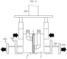
FIG. 6 is a schematic diagram for explaining a pre-working device of the assembling system for a battery module assembly ofFIG. 1 . - Referring to
FIG. 6 andFIG. 1 above, prior to the assembly process of thecell assembly 7 through the aligningdevice 200 and the assembly process of thebattery module assembly 1 through thestructure assembling device 400, thepre-working device 500 may perform the preprocessing process of thecooling unit 5 and theside structure unit 9. - The
pre-working device 500 may include aplasma processing unit 510, anadhesive processing unit 530, and adirection changing unit 550. - The
plasma processing unit 510 is for treating plasma P toward thecooling unit 5, and may be slidably provided along the longitudinal direction of thecooling unit 5. - The
adhesive processing unit 530 is for applying adhesive G to thecooling unit 5 and theside structure unit 9, and may be slidably provided along the longitudinal direction of thecooling unit 5 and theside structure unit 9. - The
direction changing unit 550 may guide the treatment of the plasma P and the application of the adhesive G and support thecooling unit 5 or theside structure unit 9 during the treatment of the plasma P or the application of the adhesive G. - The
direction changing unit 550 may change the direction of thecooling unit 5 or theside structure unit 9 so that the treatment of the plasma P or the application of the adhesive G may be performed to both side surfaces of thecooling unit 5 or theside structure unit 9. - Meanwhile, the assembling
system 10 may include theceiling rail 600. - Referring back to
FIG. 1 , theceiling rail 600 is provided on the ceiling of the assemblingsystem 10 and may guide the sliding operation of thelift unit 150 of thefirst transfer device 100 and thesecond transfer device 300. - In the assembling
system 10 according to this embodiment, since theceiling rail 600 is provided on the ceiling of the system to guide the transfer, etc., space utilization of the entire system may be maximized and space for system equipment construction may be saved. - Hereinafter, the assembly process of the
battery module assembly 1 through the assemblingsystem 10 of thebattery module assembly 1 according to this embodiment will be described in more detail. -
FIGS. 7 and8 are diagrams for explaining the operation of a first transfer device of the assembling system for a battery module assembly ofFIG. 1 . - Referring to
FIGS. 7 and8 , thelift unit 150 of thefirst transfer device 100 may transfer the two rows ofbattery cells 3 on thefirst conveyor 110 toward thesecond conveyor 130. - Here, the
lift unit 150 may lift the two rows ofbattery cells 3 on thefirst conveyor 110 through adsorption, etc., move them along theceiling rail 600 toward thesecond conveyor 130 by a predetermined distance, and then descend to place them on thesecond conveyor 130. -
FIGS. 9 to 13 are diagrams for explaining the operation of the aligning device of the assembling system for a battery module assembly ofFIG. 1 . - Referring to
FIGS. 9 to 13 , the aligningdevice 200 may arrange thecooling unit 5 between the two rows ofbattery cells 3 transferred from thefirst transfer device 100 to bring the two rows ofbattery cells 3 and thecooling unit 5 into close contact, thereby forming thecell assembly 7. - Specifically, referring to
FIGS. 9 to 11 , the pair of guide jigs 210 may pressurize thebattery cells 3 of each row to come into close contact with thecooling unit 5. Here, the pair of cellspacing adjusting jigs 220 may adjust the spacing between thebattery cells 3 in each row while sliding through theguide jig 210. - Since the adhesive G is applied to both side surfaces of the
cooling unit 5 through thepre-working device 500, thebattery cells 3 and thecooling unit 5 may be bonded to each other when they are in close contact. Thecell assembly 7 may be formed by mutually bonding thebattery cells 3 and thecooling unit 5. - Referring to
FIGS. 12 and13 , the pair of guide jigs 210 may slide in a direction away from thecell assembly 7, and the aligninggripper 250 may press both sides of the upper end of thecell assembly 7. Accordingly, the coupling strength between thebattery cells 3 and thecooling unit 5 at the upper end of thecell assembly 7 may be further increased. Then, the aligninggripper 250 may lift thecell assembly 7 and guide thecell assembly 7 to a subsequent process. -
FIGS. 14 to 16 are diagrams for explaining the operation of an aligning device according to another embodiment of the assembling system for a battery module assembly ofFIG. 1 . - Since the aligning
device 200 according to this embodiment is similar to the aligningdevice 205 of the previous embodiment, redundant description of components identical as or similar to those of the previous embodiment will be omitted, and hereinafter, the focus will be on differences from the previous embodiment. - Referring to
FIGS. 14 to 16 , the aligningdevice 205 may include a pair of guide jigs 215 provided to be tiltable at a predetermined angle with the coolingunit gripper 230 interposed therebetween. - The pair of guide jigs 215 may be arranged to be inclined at a predetermined angle before the two rows of
battery cells 3 and thecooling unit 5 come into close contact, so that thebattery cells 3 in each row may be more stably supported. - Since the pair of guide jigs 215 are tilted at the predetermined angle, it is possible to press the
battery cells 3 of each row to come into close contact with thecooling unit 5. - As such, since the pair of guide jigs 215 are provided to implement both sliding and tilting operations, the two rows of
battery cells 3 may be more stably supported during the alignment or pressing operation. -
FIGS. 17 and18 are diagrams for explaining the operation of a second transfer device of the assembling system for a battery module assembly ofFIG. 1 . - Referring to
FIGS. 17 and18 , thesecond transfer device 300 may lift thecell assembly 7 from the aligningdevice 200 and transfer it toward thestructure assembling device 400. - During such a transfer operation, the
second transfer device 300 may cure thecell assembly 7 at room temperature to further increase the bonding strength of thecell assembly 7. As such, in this embodiment, during the transfer of thesecond transfer device 300, thecell assembly 7 may be cured, so that assembly fixation efficiency may be further improved. -
FIGS. 19 to 23 are diagrams for explaining the pre-processing operation of a cooling unit through the pre-working device of the assembling system for a battery module assembly ofFIG. 1 . - Referring to
FIGS. 19 to 23 , thepre-working device 500 may perform a preprocessing process before transferring thecooling unit 5 toward the aligningdevice 200. - First, the
plasma processing unit 510 of thepre-working device 500 may treat plasma P on one side surface of both side surfaces of thecooling unit 5 while sliding along the longitudinal direction of thecooling unit 5. - Thereafter, the
adhesive processing unit 530 of thepre-working device 500 may apply the adhesive G to one side surface of both side surfaces of thecooling unit 5 while sliding along the longitudinal direction of thecooling unit 5. - When the treatment of the plasma P and the application of the adhesive G are completed on one side surface of both side surfaces of the
cooling unit 5, thedirection changing unit 550 may change the direction of thecooling unit 5. - Thereafter, the
plasma processing unit 510 of thepre-working device 500 may treat plasma P on the other side surface of both side surfaces of thecooling unit 5 while sliding along the longitudinal direction of thecooling unit 5. - In addition, the
adhesive processing unit 530 of thepre-working device 500 may apply the adhesive G to the other side surface of both side surfaces of thecooling unit 5 while sliding along the longitudinal direction of thecooling unit 5. - Thereafter, the
pre-working device 500 may transfer thecooling unit 5, where the treatment of the plasma P and the application of the adhesive G are performed on both side surfaces, toward the aligningdevice 200. -
FIGS. 24 to 26 are diagrams for explaining the pre-processing operation of a side structure unit through the pre-working device of the assembling system for a battery module assembly ofFIG. 1 . - Referring to
FIGS. 24 to 26 , thepre-working device 500 may perform a preprocessing process before transferring theside structure unit 9 toward thestructure assembling device 400. - First, the
adhesive processing unit 530 of thepre-working device 500 may apply the adhesive G to one side surface of both side surfaces of theside structure unit 9 while sliding along the longitudinal direction of theside structure unit 9. - When the application of the adhesive G is completed on one side surface of both side surfaces of the
side structure unit 9, thedirection changing unit 550 may change the direction of theside structure unit 9. - Thereafter, the
adhesive processing unit 530 of thepre-working device 500 may apply the adhesive G to the other side surface of both side surfaces of theside structure unit 9 while sliding along the longitudinal direction of theside structure unit 9. - Thereafter, the
pre-working device 500 may transfer theside structure unit 9, where the adhesive G is applied to both side surfaces, toward thestructure assembling device 400. -
FIGS. 27 to 29 are diagrams for explaining the operation of a structure assembling device of the assembling system for a battery module assembly ofFIG. 1 . - Referring to
FIGS. 27 to 29 , the assemblingbase 410 of thestructure assembling device 400 may arrange theside structure unit 9 and thecell assembly 7 to be alternately disposed. - The sliding
jig 430 may bring theside structure units 9 into close contact with thecell assembly 7 while sliding along the assemblingbase 410. Accordingly, theside structure unit 9 and thecell assembly 7 may be bonded to each other while closely contacting each other to form thebattery module assembly 1. - Hereinafter, a method of assembling the
battery module assembly 1 of the present disclosure through the assembly process through the assemblingsystem 10 will be described in detail. - In this embodiment, the assembly method of the battery module assembly (1, see
FIG. 30 ) includes the steps of transferring a plurality ofbattery cells 3 in two rows, arranging acooling unit 5 between thebattery cells 3 transferred in two rows to assemble acell assembly 7, transferring thecell assembly 7 toward theside structure unit 9 that covers thebattery cells 3 of thecell assembly 7, and covering thebattery cells 3 of thecell assembly 7 with theside structure unit 9 to assemble thebattery module assembly 1. - Here, the step of transferring the plurality of
battery cells 3 in two rows includes the steps of transferring the two rows ofbattery cells 3 through theupper conveyor 110 and transferring the two rows ofbattery cells 3 of theupper conveyor 110 to thelower conveyor 130 for assembling thecell assembly 7. - Here, the
cell assembly 7 may be formed by mutually bonding thecooling unit 5 aligned between the two rows ofbattery cells 3 to the two rows ofbattery cells 3 through adhesive G. - In addition, the
battery module assembly 1 may be formed by mutually bonding thebattery cells 3 of thecell assembly 7 and theside structure unit 9 through adhesive G. - Meanwhile, the
cell assembly 7 may be cured at room temperature when transferred to theside structure unit 9. Accordingly, thebattery cells 3 and thecooling unit 5 of thecell assembly 7 may be more firmly coupled to each other prior to being assembled with theside structure unit 9. In addition, when the cell assembly is transferred toward theside structure unit 9, it may be transferred toward theside structure unit 9 along the ceiling. -
FIG. 30 is a diagram for explaining a battery module assembly assembled through the assembling system for a battery module assembly ofFIG. 1 . - Referring to
FIG. 30 , thebattery module assembly 1 according to this embodiment may include a plurality ofcell assembly 7 having acooling unit 5 between thebattery cells 3, and a plurality ofside structure units 9 provided between the plurality ofcell assemblies 7 and forming both outermost side surfaces of thebattery module assembly 1. - Since the
battery module assembly 1 is formed only of the plurality ofcell assemblies 7 and the plurality ofside structure units 9, a frameless structure may be implemented without the same conventional frame structure. - Since the
battery module assembly 1 manufactured through the assemblingsystem 10 according to this embodiment is provided as a frameless structure, it may be slimmer than a conventional frame structure and may secure a relatively high energy density. - The present disclosure is directed to providing an
assembling system 10 and method for abattery module assembly 1, which may implement a frameless structure. - In addition, the present disclosure is directed to providing an
assembling system 10 and method for abattery module assembly 1, which may reduce manufacturing cost and minimizing an assembly space. - The present disclosure has been described in detail. However, it should be understood that the detailed description and specific examples, while indicating preferred embodiments of the disclosure, are given by way of illustration only, since various changes and modifications within the scope of the disclosure will become apparent to those skilled in the art from this detailed description.
Claims (15)
- An assembling system for a battery module assembly, comprising:a first transfer device configured to transfer a plurality of battery cells in two rows;an aligning device configured to assemble a cell assembly by aligning a cooling unit between the two rows of battery cells transferred by the first transfer device; anda second transfer device configured to transfer the cell assembly assembled by the aligning device toward a structure assembling device for assembly with a side structure unit that covers the battery cells.
- The assembling system for a battery module assembly according to claim 1, wherein the first transfer device includes:an upper conveyor configured to transfer the two rows of battery cells; anda lower conveyor configured to guide the two rows of battery cells to the aligning device
- The assembling system for a battery module assembly according to claim 2, wherein the first transfer device includes a lift unit configured to be movable up and down between the upper conveyor and the lower conveyor and transfer the two rows of battery cells of the upper conveyor to the lower conveyor.
- The assembling system for a battery module assembly according to claim 1, wherein the aligning device mutually bonds the cooling unit between the two rows of battery cells to form the cell assembly.
- The assembling system for a battery module assembly according to claim 1, wherein the second transfer device is provided to be movable along the ceiling of the assembling system for a battery module assembly.
- The assembling system for a battery module assembly according to claim 1, wherein the second transfer device cures the cell assembly at room temperature during the transfer.
- The assembling system for a battery module assembly according to claim 1, wherein the second transfer device lifts and transfers the cell assembly without changing a direction of the cell assembly.
- The assembling system for a battery module assembly according to claim 1, further comprising the structure assembling device configured to form the battery module assembly by arranging a plurality of side structure units between the battery cells of at least one cell assembly transferred by the second transfer device.
- The assembling system for a battery module assembly according to claim 8, wherein the structure assembling device mutually bonds the plurality of side structure units and the at least one cell assembly.
- An assembling method for a battery module assembly, comprising:transferring a plurality of battery cells in two rows;assembling a cell assembly by aligning a cooling unit between the battery cells transferred in two rows;transferring the cell assembly toward a side structure unit that covers the battery cells of the cell assembly; andassembling the battery module assembly by covering the battery cells of the cell assembly with the side structure unit.
- The assembling method for a battery module assembly according to claim 10, wherein said transferring of a plurality of battery cells in two rows includes:transferring the two rows of battery cells through an upper conveyor; andtransferring the two rows of battery cells of the upper conveyor to a lower conveyor for assembling the cell assembly.
- The assembling method for a battery module assembly according to claim 10, wherein the cell assembly is formed by mutually bonding the cooling unit arranged between the two rows of battery cells with the two rows of battery cells through an adhesive.
- The assembling method for a battery module assembly according to claim 10, wherein the battery module assembly is formed by mutually bonding the battery cells of the cell assembly with the side structure unit through an adhesive.
- The assembling method for a battery module assembly according to claim 10, wherein the cell assembly is cured at room temperature when transferred toward the side structure unit.
- The assembling method for a battery module assembly according to claim 10, wherein when transferred toward the side structure unit, the cell assembly is transferred toward the side structure unit along the ceiling.
Applications Claiming Priority (3)
| Application Number | Priority Date | Filing Date | Title |
|---|---|---|---|
| KR20210174261 | 2021-12-07 | ||
| KR20210189013 | 2021-12-27 | ||
| PCT/KR2022/019638 WO2023106773A1 (en) | 2021-12-07 | 2022-12-05 | Assembly system and assembly method of battery module assembly |
Publications (2)
| Publication Number | Publication Date |
|---|---|
| EP4383427A1 true EP4383427A1 (en) | 2024-06-12 |
| EP4383427A4 EP4383427A4 (en) | 2025-07-09 |
Family
ID=86730868
Family Applications (1)
| Application Number | Title | Priority Date | Filing Date |
|---|---|---|---|
| EP22904603.2A Pending EP4383427A4 (en) | 2021-12-07 | 2022-12-05 | MOUNTING SYSTEM AND MOUNTING METHOD FOR BATTERY MODULE ASSEMBLY |
Country Status (4)
| Country | Link |
|---|---|
| EP (1) | EP4383427A4 (en) |
| JP (1) | JP7733802B2 (en) |
| KR (1) | KR102894304B1 (en) |
| WO (1) | WO2023106773A1 (en) |
Families Citing this family (2)
| Publication number | Priority date | Publication date | Assignee | Title |
|---|---|---|---|---|
| KR102592629B1 (en) * | 2023-06-15 | 2023-10-25 | (주)홍진기업 | Method for manufacturing lithium battery pack |
| KR102712512B1 (en) * | 2024-02-16 | 2024-10-02 | 주식회사 대양계기 | Modular electric vehicle charger |
Family Cites Families (11)
| Publication number | Priority date | Publication date | Assignee | Title |
|---|---|---|---|---|
| DE10034134A1 (en) * | 2000-07-13 | 2002-01-31 | Daimler Chrysler Ag | Heat exchanger structure for several electrochemical storage cells |
| KR100388648B1 (en) * | 2001-05-23 | 2003-06-25 | 주식회사 코캄엔지니어링 | Automated manufacturing system of lithium secondary cell |
| KR100803001B1 (en) * | 2002-09-25 | 2008-02-14 | 주식회사 에스에프에이 | Battery manufacturing apparatus and method |
| JP2014093241A (en) * | 2012-11-06 | 2014-05-19 | Nissan Motor Co Ltd | Battery module |
| JP2014192094A (en) * | 2013-03-28 | 2014-10-06 | Mitsubishi Electric Corp | Storage battery module and manufacturing method for storage battery module |
| DE102014203765A1 (en) * | 2014-02-28 | 2015-09-03 | Bayerische Motoren Werke Aktiengesellschaft | A method of manufacturing an assembly of an energy storage module and a cooling element and assembly |
| KR102092108B1 (en) * | 2015-11-30 | 2020-03-23 | 주식회사 엘지화학 | Pallet Capable of Improving Productivity of Battery Pack and Battery Pack Assembling Apparatus Comprising the Same |
| KR20170071077A (en) * | 2015-12-15 | 2017-06-23 | 주식회사 엘지화학 | Apparatus for Manufacturing Battery Pack Having Plurality of Lanes for Assembling Battery Cells |
| KR102700154B1 (en) * | 2018-04-26 | 2024-08-27 | 삼성에스디아이 주식회사 | Rechargeable battery, manufacturing apparatus and manufacturing metho of the same |
| DE102019201077A1 (en) * | 2019-01-29 | 2020-07-30 | Audi Ag | Battery assembly method for providing a battery assembly and assembly |
| KR102193318B1 (en) * | 2019-03-29 | 2020-12-22 | 주식회사 디에이테크놀로지 | Apparatus for Distributing Battery Cell Parts, And System for Manufacturing Secondary Battery Cell Having the Same |
-
2022
- 2022-12-05 JP JP2024502672A patent/JP7733802B2/en active Active
- 2022-12-05 EP EP22904603.2A patent/EP4383427A4/en active Pending
- 2022-12-05 WO PCT/KR2022/019638 patent/WO2023106773A1/en not_active Ceased
- 2022-12-05 KR KR1020220168021A patent/KR102894304B1/en active Active
Also Published As
| Publication number | Publication date |
|---|---|
| JP2024526362A (en) | 2024-07-17 |
| WO2023106773A1 (en) | 2023-06-15 |
| JP7733802B2 (en) | 2025-09-03 |
| KR20230085870A (en) | 2023-06-14 |
| EP4383427A4 (en) | 2025-07-09 |
| KR102894304B1 (en) | 2025-12-02 |
Similar Documents
| Publication | Publication Date | Title |
|---|---|---|
| EP4379925A1 (en) | Alignment apparatus and assembly system of battery module assembly comprising alignment apparatus | |
| EP4383427A1 (en) | Assembly system and assembly method of battery module assembly | |
| KR102015898B1 (en) | Folding Device for electrode lead Part of Battery Cell | |
| US11982686B2 (en) | Electrode lead gripper for pressure activation device | |
| US11316190B2 (en) | Battery module, and battery pack and vehicle comprising same | |
| KR102548613B1 (en) | Jig for can type secondary battery cell | |
| KR20170100994A (en) | Pressing Device for Battery Cell, Initial Charging and Discharging System for Battery Cell Using the Same, and Method of Initial Charging And Discharging Battery Cell Using the Same | |
| US20190372079A1 (en) | Battery pack production method and production device | |
| CN110249451A (en) | Assembled battery, bus bar holder used for assembled battery, and method for manufacturing assembled battery | |
| CN104795528A (en) | Traction battery assembly | |
| KR20240105201A (en) | Align apparatus and assembly system of battery module assembly comprising the align apparatus | |
| KR102264654B1 (en) | Ultrasonic Welding Assembly Comprising Tab Alignment Part and Ultrasonic Welding Method Using the Same | |
| KR20210097903A (en) | Gripper for charging and discharging of pouch type battery, and charging and discharging device of pouch type battery having same | |
| KR102407243B1 (en) | Laser-welding method for lead tabs of battery cells | |
| KR102931768B1 (en) | Battery module, method for manufacturing the battery module, battery pack and vehicle comprising the battery module | |
| CN115084619A (en) | Stacking system of battery cell | |
| CN117652057A (en) | Assembling system and method of battery module assembly | |
| EP4266469B1 (en) | Battery module, battery pack and vehicle comprising the battery module, and method for manufacturing the battery module | |
| US20230307775A1 (en) | Traction battery pack assembling method | |
| KR102386470B1 (en) | charging and discharging device of pouch type battery | |
| KR20240101321A (en) | Align apparatus and assembly system of battery module assembly comprising the align apparatus | |
| US12525637B2 (en) | Traction battery pack assembling method | |
| KR20230014334A (en) | Automatic assembly system of sensing block for battery module | |
| US20230307776A1 (en) | Traction battery pack assembling method | |
| KR102787821B1 (en) | A device of setting battery module surface pressure for battery system production line |
Legal Events
| Date | Code | Title | Description |
|---|---|---|---|
| STAA | Information on the status of an ep patent application or granted ep patent |
Free format text: STATUS: THE INTERNATIONAL PUBLICATION HAS BEEN MADE |
|
| PUAI | Public reference made under article 153(3) epc to a published international application that has entered the european phase |
Free format text: ORIGINAL CODE: 0009012 |
|
| STAA | Information on the status of an ep patent application or granted ep patent |
Free format text: STATUS: REQUEST FOR EXAMINATION WAS MADE |
|
| 17P | Request for examination filed |
Effective date: 20240305 |
|
| AK | Designated contracting states |
Kind code of ref document: A1 Designated state(s): AL AT BE BG CH CY CZ DE DK EE ES FI FR GB GR HR HU IE IS IT LI LT LU LV MC ME MK MT NL NO PL PT RO RS SE SI SK SM TR |
|
| DAV | Request for validation of the european patent (deleted) | ||
| DAX | Request for extension of the european patent (deleted) | ||
| A4 | Supplementary search report drawn up and despatched |
Effective date: 20250612 |
|
| RIC1 | Information provided on ipc code assigned before grant |
Ipc: H01M 10/643 20140101ALN20250605BHEP Ipc: H01M 50/213 20210101ALN20250605BHEP Ipc: H01M 50/264 20210101ALI20250605BHEP Ipc: H01M 10/625 20140101ALI20250605BHEP Ipc: H01M 10/052 20100101ALI20250605BHEP Ipc: F28D 1/03 20060101ALI20250605BHEP Ipc: H01M 10/6557 20140101ALI20250605BHEP Ipc: H01M 10/6555 20140101ALI20250605BHEP Ipc: H01M 10/613 20140101ALI20250605BHEP Ipc: H01M 10/04 20060101ALI20250605BHEP Ipc: H01M 50/249 20210101ALI20250605BHEP Ipc: H01M 50/247 20210101ALI20250605BHEP Ipc: H01M 50/256 20210101AFI20250605BHEP |
|
| RIC1 | Information provided on ipc code assigned before grant |
Ipc: H01M 50/256 20210101AFI20260122BHEP Ipc: H01M 50/247 20210101ALI20260122BHEP Ipc: H01M 50/249 20210101ALI20260122BHEP Ipc: H01M 10/04 20060101ALI20260122BHEP Ipc: H01M 10/613 20140101ALI20260122BHEP Ipc: H01M 10/6555 20140101ALI20260122BHEP Ipc: H01M 10/6557 20140101ALI20260122BHEP Ipc: F28D 1/03 20060101ALI20260122BHEP Ipc: H01M 10/052 20100101ALI20260122BHEP Ipc: H01M 10/625 20140101ALI20260122BHEP Ipc: H01M 50/264 20210101ALI20260122BHEP Ipc: H01M 50/213 20210101ALN20260122BHEP Ipc: H01M 10/643 20140101ALN20260122BHEP |
|
| GRAP | Despatch of communication of intention to grant a patent |
Free format text: ORIGINAL CODE: EPIDOSNIGR1 |
|
| RIC1 | Information provided on ipc code assigned before grant |
Ipc: H01M 50/256 20210101AFI20260226BHEP Ipc: H01M 50/247 20210101ALI20260226BHEP Ipc: H01M 50/249 20210101ALI20260226BHEP Ipc: H01M 10/04 20060101ALI20260226BHEP Ipc: H01M 10/613 20140101ALI20260226BHEP Ipc: H01M 10/6555 20140101ALI20260226BHEP Ipc: H01M 10/6557 20140101ALI20260226BHEP Ipc: F28D 1/03 20060101ALI20260226BHEP Ipc: H01M 10/052 20100101ALI20260226BHEP Ipc: H01M 10/625 20140101ALI20260226BHEP Ipc: H01M 50/264 20210101ALI20260226BHEP Ipc: H01M 50/213 20210101ALN20260226BHEP Ipc: H01M 10/643 20140101ALN20260226BHEP |
|
| STAA | Information on the status of an ep patent application or granted ep patent |
Free format text: STATUS: GRANT OF PATENT IS INTENDED |