EP4383386A1 - Battery cell with improved heat transfer - Google Patents
Battery cell with improved heat transfer Download PDFInfo
- Publication number
- EP4383386A1 EP4383386A1 EP22212540.3A EP22212540A EP4383386A1 EP 4383386 A1 EP4383386 A1 EP 4383386A1 EP 22212540 A EP22212540 A EP 22212540A EP 4383386 A1 EP4383386 A1 EP 4383386A1
- Authority
- EP
- European Patent Office
- Prior art keywords
- vertical edge
- cell
- battery cell
- casing
- cell casing
- Prior art date
- Legal status (The legal status is an assumption and is not a legal conclusion. Google has not performed a legal analysis and makes no representation as to the accuracy of the status listed.)
- Pending
Links
Images

Classifications
-
- H—ELECTRICITY
- H01—ELECTRIC ELEMENTS
- H01M—PROCESSES OR MEANS, e.g. BATTERIES, FOR THE DIRECT CONVERSION OF CHEMICAL ENERGY INTO ELECTRICAL ENERGY
- H01M50/00—Constructional details or processes of manufacture of the non-active parts of electrochemical cells other than fuel cells, e.g. hybrid cells
- H01M50/10—Primary casings; Jackets or wrappings
- H01M50/102—Primary casings; Jackets or wrappings characterised by their shape or physical structure
- H01M50/103—Primary casings; Jackets or wrappings characterised by their shape or physical structure prismatic or rectangular
-
- H—ELECTRICITY
- H01—ELECTRIC ELEMENTS
- H01M—PROCESSES OR MEANS, e.g. BATTERIES, FOR THE DIRECT CONVERSION OF CHEMICAL ENERGY INTO ELECTRICAL ENERGY
- H01M50/00—Constructional details or processes of manufacture of the non-active parts of electrochemical cells other than fuel cells, e.g. hybrid cells
- H01M50/10—Primary casings; Jackets or wrappings
- H01M50/172—Arrangements of electric connectors penetrating the casing
- H01M50/174—Arrangements of electric connectors penetrating the casing adapted for the shape of the cells
- H01M50/179—Arrangements of electric connectors penetrating the casing adapted for the shape of the cells for cells having curved cross-section, e.g. round or elliptic
-
- H—ELECTRICITY
- H01—ELECTRIC ELEMENTS
- H01M—PROCESSES OR MEANS, e.g. BATTERIES, FOR THE DIRECT CONVERSION OF CHEMICAL ENERGY INTO ELECTRICAL ENERGY
- H01M10/00—Secondary cells; Manufacture thereof
- H01M10/60—Heating or cooling; Temperature control
- H01M10/65—Means for temperature control structurally associated with the cells
- H01M10/653—Means for temperature control structurally associated with the cells characterised by electrically insulating or thermally conductive materials
-
- H—ELECTRICITY
- H01—ELECTRIC ELEMENTS
- H01M—PROCESSES OR MEANS, e.g. BATTERIES, FOR THE DIRECT CONVERSION OF CHEMICAL ENERGY INTO ELECTRICAL ENERGY
- H01M10/00—Secondary cells; Manufacture thereof
- H01M10/04—Construction or manufacture in general
- H01M10/0431—Cells with wound or folded electrodes
-
- H—ELECTRICITY
- H01—ELECTRIC ELEMENTS
- H01M—PROCESSES OR MEANS, e.g. BATTERIES, FOR THE DIRECT CONVERSION OF CHEMICAL ENERGY INTO ELECTRICAL ENERGY
- H01M10/00—Secondary cells; Manufacture thereof
- H01M10/05—Accumulators with non-aqueous electrolyte
- H01M10/058—Construction or manufacture
- H01M10/0587—Construction or manufacture of accumulators having only wound construction elements, i.e. wound positive electrodes, wound negative electrodes and wound separators
-
- H—ELECTRICITY
- H01—ELECTRIC ELEMENTS
- H01M—PROCESSES OR MEANS, e.g. BATTERIES, FOR THE DIRECT CONVERSION OF CHEMICAL ENERGY INTO ELECTRICAL ENERGY
- H01M10/00—Secondary cells; Manufacture thereof
- H01M10/60—Heating or cooling; Temperature control
- H01M10/61—Types of temperature control
- H01M10/613—Cooling or keeping cold
-
- H—ELECTRICITY
- H01—ELECTRIC ELEMENTS
- H01M—PROCESSES OR MEANS, e.g. BATTERIES, FOR THE DIRECT CONVERSION OF CHEMICAL ENERGY INTO ELECTRICAL ENERGY
- H01M10/00—Secondary cells; Manufacture thereof
- H01M10/60—Heating or cooling; Temperature control
- H01M10/62—Heating or cooling; Temperature control specially adapted for specific applications
- H01M10/625—Vehicles
-
- H—ELECTRICITY
- H01—ELECTRIC ELEMENTS
- H01M—PROCESSES OR MEANS, e.g. BATTERIES, FOR THE DIRECT CONVERSION OF CHEMICAL ENERGY INTO ELECTRICAL ENERGY
- H01M10/00—Secondary cells; Manufacture thereof
- H01M10/60—Heating or cooling; Temperature control
- H01M10/64—Heating or cooling; Temperature control characterised by the shape of the cells
- H01M10/643—Cylindrical cells
-
- H—ELECTRICITY
- H01—ELECTRIC ELEMENTS
- H01M—PROCESSES OR MEANS, e.g. BATTERIES, FOR THE DIRECT CONVERSION OF CHEMICAL ENERGY INTO ELECTRICAL ENERGY
- H01M10/00—Secondary cells; Manufacture thereof
- H01M10/60—Heating or cooling; Temperature control
- H01M10/65—Means for temperature control structurally associated with the cells
- H01M10/654—Means for temperature control structurally associated with the cells located inside the innermost case of the cells, e.g. mandrels, electrodes or electrolytes
-
- H—ELECTRICITY
- H01—ELECTRIC ELEMENTS
- H01M—PROCESSES OR MEANS, e.g. BATTERIES, FOR THE DIRECT CONVERSION OF CHEMICAL ENERGY INTO ELECTRICAL ENERGY
- H01M4/00—Electrodes
- H01M4/02—Electrodes composed of, or comprising, active material
- H01M4/13—Electrodes for accumulators with non-aqueous electrolyte, e.g. for lithium-accumulators; Processes of manufacture thereof
-
- H—ELECTRICITY
- H01—ELECTRIC ELEMENTS
- H01M—PROCESSES OR MEANS, e.g. BATTERIES, FOR THE DIRECT CONVERSION OF CHEMICAL ENERGY INTO ELECTRICAL ENERGY
- H01M50/00—Constructional details or processes of manufacture of the non-active parts of electrochemical cells other than fuel cells, e.g. hybrid cells
- H01M50/50—Current conducting connections for cells or batteries
- H01M50/528—Fixed electrical connections, i.e. not intended for disconnection
-
- H—ELECTRICITY
- H01—ELECTRIC ELEMENTS
- H01M—PROCESSES OR MEANS, e.g. BATTERIES, FOR THE DIRECT CONVERSION OF CHEMICAL ENERGY INTO ELECTRICAL ENERGY
- H01M50/00—Constructional details or processes of manufacture of the non-active parts of electrochemical cells other than fuel cells, e.g. hybrid cells
- H01M50/50—Current conducting connections for cells or batteries
- H01M50/531—Electrode connections inside a battery casing
- H01M50/533—Electrode connections inside a battery casing characterised by the shape of the leads or tabs
-
- H—ELECTRICITY
- H01—ELECTRIC ELEMENTS
- H01M—PROCESSES OR MEANS, e.g. BATTERIES, FOR THE DIRECT CONVERSION OF CHEMICAL ENERGY INTO ELECTRICAL ENERGY
- H01M50/00—Constructional details or processes of manufacture of the non-active parts of electrochemical cells other than fuel cells, e.g. hybrid cells
- H01M50/50—Current conducting connections for cells or batteries
- H01M50/543—Terminals
- H01M50/545—Terminals formed by the casing of the cells
-
- H—ELECTRICITY
- H01—ELECTRIC ELEMENTS
- H01M—PROCESSES OR MEANS, e.g. BATTERIES, FOR THE DIRECT CONVERSION OF CHEMICAL ENERGY INTO ELECTRICAL ENERGY
- H01M4/00—Electrodes
- H01M4/02—Electrodes composed of, or comprising, active material
- H01M2004/026—Electrodes composed of, or comprising, active material characterised by the polarity
- H01M2004/027—Negative electrodes
-
- H—ELECTRICITY
- H01—ELECTRIC ELEMENTS
- H01M—PROCESSES OR MEANS, e.g. BATTERIES, FOR THE DIRECT CONVERSION OF CHEMICAL ENERGY INTO ELECTRICAL ENERGY
- H01M2220/00—Batteries for particular applications
- H01M2220/20—Batteries in motive systems, e.g. vehicle, ship, plane
-
- Y—GENERAL TAGGING OF NEW TECHNOLOGICAL DEVELOPMENTS; GENERAL TAGGING OF CROSS-SECTIONAL TECHNOLOGIES SPANNING OVER SEVERAL SECTIONS OF THE IPC; TECHNICAL SUBJECTS COVERED BY FORMER USPC CROSS-REFERENCE ART COLLECTIONS [XRACs] AND DIGESTS
- Y02—TECHNOLOGIES OR APPLICATIONS FOR MITIGATION OR ADAPTATION AGAINST CLIMATE CHANGE
- Y02E—REDUCTION OF GREENHOUSE GAS [GHG] EMISSIONS, RELATED TO ENERGY GENERATION, TRANSMISSION OR DISTRIBUTION
- Y02E60/00—Enabling technologies; Technologies with a potential or indirect contribution to GHG emissions mitigation
- Y02E60/10—Energy storage using batteries
-
- Y—GENERAL TAGGING OF NEW TECHNOLOGICAL DEVELOPMENTS; GENERAL TAGGING OF CROSS-SECTIONAL TECHNOLOGIES SPANNING OVER SEVERAL SECTIONS OF THE IPC; TECHNICAL SUBJECTS COVERED BY FORMER USPC CROSS-REFERENCE ART COLLECTIONS [XRACs] AND DIGESTS
- Y02—TECHNOLOGIES OR APPLICATIONS FOR MITIGATION OR ADAPTATION AGAINST CLIMATE CHANGE
- Y02P—CLIMATE CHANGE MITIGATION TECHNOLOGIES IN THE PRODUCTION OR PROCESSING OF GOODS
- Y02P70/00—Climate change mitigation technologies in the production process for final industrial or consumer products
- Y02P70/50—Manufacturing or production processes characterised by the final manufactured product
Definitions
- the disclosure relates generally to a battery cell.
- the disclosure relates to a cylindrical or prismatic battery cell with improved heat transfer.
- the disclosure can be applied in any application using a battery cell, but in particular in vehicles, such as electrical vehicles and heavy-duty vehicles, such as trucks, buses, and construction equipment.
- Prismatic cells may also have a stacked electrode assembly configuration.
- the battery cells are usually cooled down by applying cooling to the cell casing. Since the heat is generated within the cell, this cooling takes a long time as heat transfer in a radial direction is much slower compared to heat transfer in a plane direction.
- the heat generated in the electrode assembly must be removed since otherwise the battery cell may become overheated, age too quickly or create safety hazards or loose efficiency too quickly. There is thus a need for a new and improved cell design for a cylindrical and prismatic battery cell.
- a battery cell comprising a cell casing, and an electrode assembly comprising a negative electrode and a positive electrode, and at least two insulating layers in a sandwich configuration, wherein said negative electrode comprises a current collector and a negative electrode material coating arranged thereon, and has an outer vertical edge extending along a vertical axis, and which is facing said cell casing, wherein said outer vertical edge is attached to said cell casing by at least 80 % of the length of the vertical edge.
- the first aspect of the disclosure may seek to provide for a reduced cell aging with time and usage.
- a technical benefit may include improved and more efficient cooling of the inside of the cell by means of heat conduction.
- By attaching the edge of the negative electrode to the cell casing an increased surface area for heat transfer between the cell casing and the inside of the electrode assembly is achieved, through the direct cooling of the negative electrode. This means that the cooling of the body or can of the battery cell will be more efficiently transferred to the inside of the battery cell, and this may reduce ageing effects, improve the function and life-time of the battery cell.
- the vertical edge of said current collector may be attached to said cell casing.
- a technical benefit may include a more efficient heat transfer through the current collector, which often is a copper foil.
- said vertical edge of said current collector may have a reinforced portion arranged along the length of the vertical edge.
- reinforced portion is meant that the current collector is thicker at the edge portion.
- a technical benefit of the reinforced edge may include ensuring that the attachment to the cell casing is stable and does not break.
- said outer vertical edge may be attached to said cell casing by at least 90 %, or at least 95 %, or at least 99 % of the length of the vertical edge.
- a technical benefit of attaching substantially the complete edge of the edge to the cell casing is that the heat efficient transfer and cooling is ensured.
- the battery cell according to the first aspect further may comprise a soldered portion arranged between said vertical edge and said cell casing.
- the soldered portion ensures the connection between the cell casing and the electrode.
- the soldered portion may comprise a material having a thermal conductivity in the range of 50 to 400 W/m ⁇ K.
- Conventional soldering materials, such as tin has a thermal conductivity around 50 W/m K.
- the soldering portion or the soldering material used in the present disclosure is preferably formed by a material with a thermal conductivity in the higher range, and the technical benefit may include an increase in the heat transfer and cooling.
- a vehicle comprising the battery cell according to the first aspect.
- the second aspect of the disclosure may seek to provide a vehicle comprising a battery pack with an improved life-time, which is beneficial from both an environmental and sustainability aspect.
- a method for manufacturing a battery cell comprising: providing a cell casing; providing an electrode assembly comprising a negative electrode, a positive electrode, and at least two insulating layers in a sandwich configuration, and wherein said negative electrode comprises a current collector and a negative electrode material coated thereon; placing said electrode assembly into said cell casing and attaching an outer vertical edge of said negative electrode to said cell casing, wherein said outer vertical edge is attached to cell casing by at least 80 % of the length of the vertical edge.
- the third aspect of the disclosure may seek to provide for a reduced cell aging with time and usage.
- the method may further comprise arranging said electrode assembly to form a rolled-up sandwich configuration before placing said rolled-up sandwich configuration into said cell casing.
- the method may further comprise arranging said electrode assembly to form a stacked configuration, before placing said stacked configuration into said cell casing.
- said vertical edge may be attached to the cell casing by at least 90 %, or at least 95 % or at least 99 % of the length of the vertical edge.
- a technical benefit of attaching substantially the complete edge of the edge to the cell casing is that the heat efficient transfer and cooling is ensured.
- a vertical edge of said current collector may be attached to said cell casing.
- said vertical edge may be attached to said cell casing by soldering, such that a soldered portion is formed between said vertical edge and said cell casing.
- the technical benefit of the soldered portion may include ensuring that the connection between the cell casing and the electrode is stable.
- the electrode assembly 3 comprises a negative electrode 4 and a positive electrode 5, and insulating layers 6, 6' arranged in a sandwich configuration.
- the electrode assembly 3 is rolled-up into a so called jelly-roll or Swiss roll assembly.
- the rolled-up assembly or configuration 3' is placed in the cell casing 2 to form a cylindrical battery cell 1. This type of configuration can also be seen in a prismatic cell (not shown).
- the negative electrode or anode 4 has two opposing longitudinal edges 11, 11' and two opposing vertical edges 12. Only the outer vertical edge 12 is showing in Fig. 1 as the opposing vertical edge is arranged at the center portion 13 of the rolled-up electrode assembly 3.
- the vertical edge 12 extends along a vertical axis A, i.e. along the length of the cylindrical battery cell.
- the longitudinal edges 11, 11' are arranged such that it is facing the top portion 10 and bottom portion 9 of the cell casing 2 respectively.
- the outer vertical edge 12 may according to one alternative be attached to the cell casing 2, by at least 90 % of the vertical edge.
- the vertical edge 12 may be attached to the casing 2 by soldering the outer vertical edge 12 to the casing.
- a soldered portion (not shown in Fig. 1 ) may thus be formed between the casing 2 and the outer vertical edge 12.
- a vertical edge 12 of the current collector 8 of the negative electrode 4 in a jelly-roll configuration 3' may be attached to the cell casing 2 of a cylindrical or prismatic battery cell.
- the current collector 8 (or the conductive substrate) may thus have an uncoated or extended portion which is attached to the cell casing.
- Example 1 A battery cell 1 comprising a cell casing 2, and an electrode assembly 3 comprising a negative electrode 4 and a positive electrode 5, and at least two insulating layers 6, 6' in a sandwich configuration, wherein said negative electrode 4 comprises a current collector 7 and a negative electrode material 8 coating arranged thereon, and has an outer vertical edge 12 extending along a vertical axis A, and which is facing said cell casing 2, wherein said outer vertical edge 12 is attached to said cell casing 2 by at least 80 % of the length of the vertical edge.
- Example 2 The battery cell 1 according to the example 1, wherein a vertical edge 12 of said current collector 7 is attached to said cell casing 2.
- Example 3 The battery cell 1 according to example 1 or 2, wherein said vertical edge 12 of said current collector 7 has a reinforced portion arranged along the length of the vertical edge.
- Example 6 The battery cell according to any one of examples 1 to 3, wherein said outer vertical edge 12 is attached to said cell casing 2 by at least 99 % of the length of the vertical edge.
- Example 8 The battery cell of example 7, wherein said soldered portion comprises a material having a thermal conductivity in the range of 50 to 400 W/m ⁇ K.
- Example 9 The battery cell according to any one of examples 1 to 8, wherein said battery cell is any one of a cylindrical battery cell and a prismatic battery cell.
- Example 10 A vehicle comprising the battery cell according to any of examples 1-9.
- Example 11 A method for manufacturing a battery cell 1 according to any one of examples 1 to 9, comprising: providing a cell casing 2; providing an electrode assembly 3 comprising a negative electrode 4, a positive electrode 5, and at least two insulating layers 6, 6' in a sandwich configuration, and wherein said negative electrode 4 comprises a current collector 7 and a negative electrode material 8 coated thereon; placing said electrode assembly 3 into said cell casing 2; and attaching an outer vertical edge 7 of said negative electrode 4 to said cell casing 2, wherein said outer vertical edge 12 is attached to cell casing 2 by at least 80 % of the length of the vertical edge 12.
- Example 12 The method for manufacturing said battery cell 1 according to example 11, wherein the method further comprises: arranging said electrode assembly to form a rolled-up sandwich configuration 3' before placing said rolled-up sandwich configuration 3' into said cell casing 2.
- Example 13 The method for manufacturing said battery cell 1 according to claim 11, wherein the method further comprises: arranging said electrode assembly to form a stacked configuration 14, before placing said stacked configuration into said cell casing 2.
- Example 19 The method for manufacturing a battery cell 1 according to any one of examples 11 to 18, wherein said vertical edge 12 is attached to said cell casing 2 by soldering such that a soldered portion is formed between said vertical edge 12 and said cell casing.
- Example 20 The method for manufacturing a battery cell 1 according to example 19, wherein said soldered portion comprises a material having a thermal conductivity in the range of 50 to 400 W/m K.
- Relative terms such as “below” or “above” or “upper” or “lower” or “horizontal” or “vertical” may be used herein to describe a relationship of one element to another element as illustrated in the Figures. It will be understood that these terms and those discussed above are intended to encompass different orientations of the device in addition to the orientation depicted in the Figures. It will be understood that when an element is referred to as being “connected” or “coupled” to another element, it can be directly connected or coupled to the other element, or intervening elements may be present. In contrast, when an element is referred to as being “directly connected” or “directly coupled” to another element, there are no intervening elements present.
Landscapes
- Chemical & Material Sciences (AREA)
- Chemical Kinetics & Catalysis (AREA)
- Electrochemistry (AREA)
- General Chemical & Material Sciences (AREA)
- Engineering & Computer Science (AREA)
- Manufacturing & Machinery (AREA)
- Materials Engineering (AREA)
- Sealing Battery Cases Or Jackets (AREA)
- Secondary Cells (AREA)
Abstract
A battery cell (1) comprising a cell casing (2), and an electrode assembly (3) comprising a negative electrode (4) and a positive electrode (5), and at least two insulating layers (6, 6') in a sandwich configuration, wherein said negative electrode (4) comprises a current collector (7) and a negative electrode material (8) coating arranged thereon, and has an outer vertical edge (12) extending along a vertical axis (A), and which is facing said cell casing (2), wherein said outer vertical edge (12) is attached to said cell casing (2) by at least 80 % of the length of the vertical edge.
Description
- The disclosure relates generally to a battery cell. In particular aspects, the disclosure relates to a cylindrical or prismatic battery cell with improved heat transfer. The disclosure can be applied in any application using a battery cell, but in particular in vehicles, such as electrical vehicles and heavy-duty vehicles, such as trucks, buses, and construction equipment.
- Generally during use of cylindrical and prismatic battery cells, in particular jelly-roll or Swiss roll battery cells, heat is generated during the charge and discharge operations inside the electrode assembly of the cell. Prismatic cells may also have a stacked electrode assembly configuration. The battery cells are usually cooled down by applying cooling to the cell casing. Since the heat is generated within the cell, this cooling takes a long time as heat transfer in a radial direction is much slower compared to heat transfer in a plane direction. The heat generated in the electrode assembly must be removed since otherwise the battery cell may become overheated, age too quickly or create safety hazards or loose efficiency too quickly. There is thus a need for a new and improved cell design for a cylindrical and prismatic battery cell.
- According to a first aspect of the disclosure, there is provided a battery cell comprising a cell casing, and an electrode assembly comprising a negative electrode and a positive electrode, and at least two insulating layers in a sandwich configuration, wherein said negative electrode comprises a current collector and a negative electrode material coating arranged thereon, and has an outer vertical edge extending along a vertical axis, and which is facing said cell casing, wherein said outer vertical edge is attached to said cell casing by at least 80 % of the length of the vertical edge.
- The first aspect of the disclosure may seek to provide for a reduced cell aging with time and usage. A technical benefit may include improved and more efficient cooling of the inside of the cell by means of heat conduction. By attaching the edge of the negative electrode to the cell casing, an increased surface area for heat transfer between the cell casing and the inside of the electrode assembly is achieved, through the direct cooling of the negative electrode. This means that the cooling of the body or can of the battery cell will be more efficiently transferred to the inside of the battery cell, and this may reduce ageing effects, improve the function and life-time of the battery cell.
- In some examples, the vertical edge of said current collector may be attached to said cell casing. A technical benefit may include a more efficient heat transfer through the current collector, which often is a copper foil.
- In some examples, said vertical edge of said current collector may have a reinforced portion arranged along the length of the vertical edge. By reinforced portion is meant that the current collector is thicker at the edge portion. A technical benefit of the reinforced edge may include ensuring that the attachment to the cell casing is stable and does not break.
- In some examples, said outer vertical edge may be attached to said cell casing by at least 90 %, or at least 95 %, or at least 99 % of the length of the vertical edge. A technical benefit of attaching substantially the complete edge of the edge to the cell casing is that the heat efficient transfer and cooling is ensured.
- In some examples, the battery cell according to the first aspect further may comprise a soldered portion arranged between said vertical edge and said cell casing. The soldered portion ensures the connection between the cell casing and the electrode.
- In some examples, the soldered portion may comprise a material having a thermal conductivity in the range of 50 to 400 W/m·K. Conventional soldering materials, such as tin has a thermal conductivity around 50 W/m K. The soldering portion or the soldering material used in the present disclosure is preferably formed by a material with a thermal conductivity in the higher range, and the technical benefit may include an increase in the heat transfer and cooling.
- In some examples, the battery cell may be any one of a cylindrical battery cell and a prismatic battery cell.
- According to a second aspect of the disclosure, there is provided a vehicle comprising the battery cell according to the first aspect. The second aspect of the disclosure may seek to provide a vehicle comprising a battery pack with an improved life-time, which is beneficial from both an environmental and sustainability aspect. Although the disclosure may be described with respect to a particular vehicle, the disclosure is not restricted to any particular vehicle.
- According to a third aspect of the disclosure, there is provided a method for manufacturing a battery cell according to the first aspect, comprising: providing a cell casing; providing an electrode assembly comprising a negative electrode, a positive electrode, and at least two insulating layers in a sandwich configuration, and wherein said negative electrode comprises a current collector and a negative electrode material coated thereon; placing said electrode assembly into said cell casing and attaching an outer vertical edge of said negative electrode to said cell casing, wherein said outer vertical edge is attached to cell casing by at least 80 % of the length of the vertical edge. The third aspect of the disclosure may seek to provide for a reduced cell aging with time and usage.
- In some examples, the method may further comprise arranging said electrode assembly to form a rolled-up sandwich configuration before placing said rolled-up sandwich configuration into said cell casing.
- In some alternative examples, the method may further comprise arranging said electrode assembly to form a stacked configuration, before placing said stacked configuration into said cell casing.
- In some examples, said vertical edge may be attached to the cell casing by at least 90 %, or at least 95 % or at least 99 % of the length of the vertical edge. A technical benefit of attaching substantially the complete edge of the edge to the cell casing is that the heat efficient transfer and cooling is ensured.
- In some examples, a vertical edge of said current collector may be attached to said cell casing.
- In some examples, said vertical edge of said current collector may have a reinforced portion arranged along the length of the vertical edge.
- In some examples, said vertical edge may be attached to said cell casing by soldering, such that a soldered portion is formed between said vertical edge and said cell casing. The technical benefit of the soldered portion may include ensuring that the connection between the cell casing and the electrode is stable.
- In some examples, the soldered portion may comprise a material having a thermal conductivity in the range of 50 to 400 W/m·K. Conventional soldering materials, such as tin has a thermal conductivity around 50 W/m K. The soldering portion or the soldering material used in the present disclosure is preferably formed by a material with a thermal conductivity in the higher range, and the technical benefit may include an increase in the heat transfer and cooling.
- The above aspects, accompanying claims, and/or examples disclosed herein above and later below may be suitably combined with each other as would be apparent to anyone of ordinary skill in the art.
Additional features and advantages are disclosed in the following description, claims, and drawings, and in part will be readily apparent therefrom to those skilled in the art or recognized by practicing the disclosure as described herein. - With reference to the appended drawings, below follows a more detailed description of aspects of the disclosure cited as examples.
-
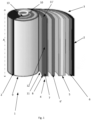
FIG. 1 is an exemplary cylindrical battery cell. -
FIGS 2A and 2B are exemplary battery cells according to the present disclosure. - Aspects set forth below represent the necessary information to enable those skilled in the art to practice the disclosure.
- Battery cells, especially in a cylindrical format, i.e. jelly-roll or Swiss roll cylindrical cell, are cooled down by applying cooling condition to a cell casing. However, the heat is generating during charge and discharge inside the jelly-roll of the cell. When cooling is applied from outer casing it takes longer time to cool down the cell jelly-roll as heat transfer in the radial direction is much slower compared to heat transfer in plane direction. Usually, cell negative pole connected at the bottom of the cylindrical casing and positive terminal at the top using soldering of small part of the current collector. This creates a slow cooling via conduction heat transfer due to the small surface area connected to cell outer casing. Cylindrical cells are often small and round, making it possible to stack them in devices of all sizes.
- Prismatic battery cells, i.e. rectangular shaped that allows for an efficient stacking of multiple cells in a battery module, may also have a jelly-roll (winding) electrode assembly configuration, or alternatively a stacked or flattened electrode assembly configuration. In the stacked configuration the anode, and cathode are arranged in layers, with interposed separator layers. The cooling principle for prismatic battery cells is substantially the same as with cylindrical battery cell, regardless if the electrode assembly is in a jelly roll or stacked configuration. Prismatic battery cells are often utilized in energy-intensive applications such as energy storage systems or in electric vehicles, due to their larger size compared to cylindrical battery cells.
- An improvement can be made by increasing the surface area of the contact of the jelly-roll or the stacked assembly with the casing of the cell. This increased surface area increase the heat transfer between the cell body and inside the electrode assembly (jelly roll or stacked) via conduction mechanism, thereby improving cooling of the cell efficiently which minimise the cell aging with time and usage. The cell casing may be cooled from the outside, by for instance a liquid coolant or through other means for cooling.
-
FIG. 1 is an exemplarycylindrical battery cell 1 according to one example. The cylindrical battery cell comprises acasing 2, having atop portion 10 and abottom portion 9, and rolled-upelectrode assembly 3. - The
electrode assembly 3 comprises anegative electrode 4 and apositive electrode 5, and insulatinglayers 6, 6' arranged in a sandwich configuration. Theelectrode assembly 3 is rolled-up into a so called jelly-roll or Swiss roll assembly. The rolled-up assembly or configuration 3' is placed in thecell casing 2 to form acylindrical battery cell 1. This type of configuration can also be seen in a prismatic cell (not shown). - In an electrolytic cell The negative electrode 4 (i.e. the anode) conventionally comprises a conductive substrate or a current collector, such as a
metal foil 7, which is coated with a negative electrode oranode material 8. The negative electrode is conventionally formed from a compound of carbon materials coating on acopper foil 7. Graphite is the most conventional material to use as carbon materials for the anode, however lithium titanate (LTO) in combination with an aluminum current collector may also be used. The positive electrode (i.e. cathode) is conventionally designed in the same manner, with a metal foil, often aluminum, coated on either or both sides with a positive electrode or cathode material, such as for instance Lithium Cobalt Oxide (LiCoO2), Lithium Manganese Oxide (LiMnO2). An electrolyte serves as an ion transfer media to make a battery conductive by promoting the movement of ions from the cathode to the anode on charge and in reverse on discharge. Ions are electrically charged atoms that have lost or gained electrons. The electrolyte of a battery conventionally consists of soluble salts, acids or other bases in liquid, gelled and dry formats. In a Li-ion battery the electrolyte may be in liquid, gel or dry polymer form. Further, a passivation film forms on the anode that is called solid electrolyte interface (SEI). This layer separates the anode from the cathode but allows ions to pass through much like a separator. - As shown in
Fig. 1 the negative electrode oranode 4 has two opposinglongitudinal edges 11, 11' and two opposing vertical edges 12. Only the outervertical edge 12 is showing inFig. 1 as the opposing vertical edge is arranged at thecenter portion 13 of the rolled-upelectrode assembly 3. Thevertical edge 12 extends along a vertical axis A, i.e. along the length of the cylindrical battery cell. When theelectrode assembly 3 is placed in thecell casing 2 thelongitudinal edges 11, 11' are arranged such that it is facing thetop portion 10 andbottom portion 9 of thecell casing 2 respectively. - The outer
vertical edge 12 is attached to thecell casing 2, by at least 80 % of the length of the vertical edge. - The outer
vertical edge 12 may according to one alternative be attached to thecell casing 2, by at least 90 % of the vertical edge. - The outer
vertical edge 12 may according to one alternative be attached to thecell casing 2, by at least 95 % of the vertical edge. - The outer
vertical edge 12 may according to an alternative be attached to thecell casing 2, by at least 99 % of the vertical edge. Preferably the complete edge (i.e. substantially 100 %) of the edge is attached to the cell casing, since this will provide the optimal heat transfer, i.e. cooling from the casing to the inside of the electrode assemble. - According to one example the
vertical edge 12 may be attached to thecasing 2 by soldering the outervertical edge 12 to the casing. A soldered portion (not shown inFig. 1 ) may thus be formed between thecasing 2 and the outervertical edge 12. - The soldered portion may comprise a material which further increases or facilitates the heat transfer from the
negative electrode 4 to thecell casing 2. Said material may further have a thermal conductivity, or bulk conductivity, in the range of 50 to 400 W/m·K. Conventional soldering materials, such as tin has a thermal conductivity around 50 W/m·K. The soldering portion or the soldering material used in the present disclosure is preferably formed by a material with a thermal conductivity in the higher range, and the technical benefit may include an increase in the heat transfer and cooling. Such materials may include copper, which the electrically conducting substrate may also be formed from. This means that in one alternative the vertical edge of the conductive substrate itself is soldered to the cell casing. In one alternative the soldering material is made of copper, i.e. the conductive substrate and the soldered portion comprise or consist of the same material. - The
vertical edge 12 may also be attached to the casing by other means or attachment arrangements, which increase or promote the heat transfer from thenegative electrode 4 to thecell casing 2. - As illustrated in
Fig. 2A avertical edge 12 of thecurrent collector 8 of thenegative electrode 4 in a jelly-roll configuration 3' may be attached to thecell casing 2 of a cylindrical or prismatic battery cell. The current collector 8 (or the conductive substrate) may thus have an uncoated or extended portion which is attached to the cell casing. - As illustrated in
Fig. 2B thevertical edge 12 of thecurrent collector 8 in a stacked configuration in a flattened or stackedelectrode assembly 14 of a prismatic battery cell may be attached to thecell casing 2. - In an alternative example the
outer edge 12 of thecurrent collector 8 may have a reinforced portion (not shown). The reinforced portion may extend along substantially the entire length of the vertical edge. By reinforced portion is means that the current collector may be thicker, as seen in a direction perpendicular to the vertical direction. - The present disclosure will now be described by way of examples.
- Example 1: A
battery cell 1 comprising acell casing 2, and anelectrode assembly 3 comprising anegative electrode 4 and apositive electrode 5, and at least twoinsulating layers 6, 6' in a sandwich configuration, wherein saidnegative electrode 4 comprises acurrent collector 7 and anegative electrode material 8 coating arranged thereon, and has an outervertical edge 12 extending along a vertical axis A, and which is facing saidcell casing 2, wherein said outervertical edge 12 is attached to saidcell casing 2 by at least 80 % of the length of the vertical edge. - Example 2: The
battery cell 1 according to the example 1, wherein avertical edge 12 of saidcurrent collector 7 is attached to saidcell casing 2. - Example 3: The
battery cell 1 according to example 1 or 2, wherein saidvertical edge 12 of saidcurrent collector 7 has a reinforced portion arranged along the length of the vertical edge. - Example 4: The battery cell according to any one of examples 1 to 3, wherein said outer
vertical edge 12 is attached to saidcell casing 2 by at least 90 % of the length of the vertical edge. - Example 5: The battery cell according to any one of examples 1 to 3, wherein said outer
vertical edge 12 is attached to saidcell casing 2 by at least 95 % of the length of the vertical edge. - Example 6: The battery cell according to any one of examples 1 to 3, wherein said outer
vertical edge 12 is attached to saidcell casing 2 by at least 99 % of the length of the vertical edge. - Example 7: The battery cell of any of examples 1-6, further comprising a soldered portion arranged between said
vertical edge 12 and saidcell casing 2. - Example 8: The battery cell of example 7, wherein said soldered portion comprises a material having a thermal conductivity in the range of 50 to 400 W/m·K.
- Example 9: The battery cell according to any one of examples 1 to 8, wherein said battery cell is any one of a cylindrical battery cell and a prismatic battery cell.
- Example 10: A vehicle comprising the battery cell according to any of examples 1-9.
- Example 11: A method for manufacturing a
battery cell 1 according to any one of examples 1 to 9, comprising: providing acell casing 2; providing anelectrode assembly 3 comprising anegative electrode 4, apositive electrode 5, and at least twoinsulating layers 6, 6' in a sandwich configuration, and wherein saidnegative electrode 4 comprises acurrent collector 7 and anegative electrode material 8 coated thereon; placing saidelectrode assembly 3 into saidcell casing 2; and attaching an outervertical edge 7 of saidnegative electrode 4 to saidcell casing 2, wherein said outervertical edge 12 is attached tocell casing 2 by at least 80 % of the length of thevertical edge 12. - Example 12: The method for manufacturing said
battery cell 1 according to example 11, wherein the method further comprises: arranging said electrode assembly to form a rolled-up sandwich configuration 3' before placing said rolled-up sandwich configuration 3' into saidcell casing 2. - Example 13: The method for manufacturing said
battery cell 1 according toclaim 11, wherein the method further comprises: arranging said electrode assembly to form a stackedconfiguration 14, before placing said stacked configuration into saidcell casing 2. - Example 14: The method for manufacturing a
battery cell 1 according to any one of examples 11 to 13, wherein saidvertical edge 12 is attached to saidcell casing 2 by at least 90 % of the length of thevertical edge 12. - Example 15: The method for manufacturing a
battery cell 1 according to any one of examples 11 to 14, wherein saidvertical edge 12 is attached to saidcell casing 2 by at least 95 % of the length of thevertical edge 12. - Example 16: The method for manufacturing a
battery cell 1 according to any one of examples 11 to 15, wherein saidvertical edge 12 is attached to saidcell casing 2 by at least 99 % of the length of thevertical edge 12. - Example 17: The method for manufacturing a
battery cell 1 according to any one of examples 11 to 15, wherein avertical edge 12 of saidcurrent collector 8 is attached to saidcell casing 2. - Example 18: The method for manufacturing a
battery cell 1 according to any one of examples 11 to 17, wherein saidvertical edge 12 of saidcurrent collector 7 has a reinforced portion arranged along the length of the vertical edge. - Example 19: The method for manufacturing a
battery cell 1 according to any one of examples 11 to 18, wherein saidvertical edge 12 is attached to saidcell casing 2 by soldering such that a soldered portion is formed between saidvertical edge 12 and said cell casing. - Example 20: The method for manufacturing a
battery cell 1 according to example 19, wherein said soldered portion comprises a material having a thermal conductivity in the range of 50 to 400 W/m K. - The terminology used herein is for the purpose of describing particular aspects only and is not intended to be limiting of the disclosure. As used herein, the singular forms "a," "an," and "the" are intended to include the plural forms as well, unless the context clearly indicates otherwise. As used herein, the term "and/or" includes any and all combinations of one or more of the associated listed items. It will be further understood that the terms "comprises," "comprising," "includes," and/or "including" when used herein specify the presence of stated features, integers, steps, operations, elements, and/or components, but do not preclude the presence or addition of one or more other features, integers, steps, operations, elements, components, and/or groups thereof.
- It will be understood that, although the terms first, second, etc., may be used herein to describe various elements, these elements should not be limited by these terms. These terms are only used to distinguish one element from another. For example, a first element could be termed a second element, and, similarly, a second element could be termed a first element without departing from the scope of the present disclosure.
- Relative terms such as "below" or "above" or "upper" or "lower" or "horizontal" or "vertical" may be used herein to describe a relationship of one element to another element as illustrated in the Figures. It will be understood that these terms and those discussed above are intended to encompass different orientations of the device in addition to the orientation depicted in the Figures. It will be understood that when an element is referred to as being "connected" or "coupled" to another element, it can be directly connected or coupled to the other element, or intervening elements may be present. In contrast, when an element is referred to as being "directly connected" or "directly coupled" to another element, there are no intervening elements present.
- Unless otherwise defined, all terms (including technical and scientific terms) used herein have the same meaning as commonly understood by one of ordinary skill in the art to which this disclosure belongs. It will be further understood that terms used herein should be interpreted as having a meaning consistent with their meaning in the context of this specification and the relevant art and will not be interpreted in an idealized or overly formal sense unless expressly so defined herein.
- It is to be understood that the present disclosure is not limited to the aspects described above and illustrated in the drawings; rather, the skilled person will recognize that many changes and modifications may be made within the scope of the present disclosure and appended claims. In the drawings and specification, there have been disclosed aspects for purposes of illustration only and not for purposes of limitation, the scope of the inventive concepts being set forth in the following claims.
Claims (15)
- A battery cell (1) comprising a cell casing (2), and an electrode assembly (3) comprising a negative electrode (4) and a positive electrode (5), and at least two insulating layers (6, 6') in a sandwich configuration, wherein said negative electrode (4) comprises a current collector (7) and a negative electrode material (8) coating arranged thereon, and has an outer vertical edge (12) extending along a vertical axis (A), and which is facing said cell casing (2), wherein said outer vertical edge (12) is attached to said cell casing (2) by at least 80 % of the length of the vertical edge.
- The battery cell (1) according to claim 1, wherein a vertical edge (12) of said current collector (7) is attached to said cell casing (2).
- The battery cell (1) according to claim 1 or 2, wherein said vertical edge (12) of said current collector (7) has a reinforced portion arranged along the length of the vertical edge.
- The battery cell according to any one of claims 1 to 3, wherein said outer vertical edge (12) is attached to said cell casing (2) by at least 90 % of the length of the vertical edge, or by at least 95 % of the length of the vertical edge, or by at least 99 % of the length of the vertical edge.
- The battery cell of any of claims 1-4, further comprising a soldered portion arranged between said vertical edge (12) and said cell casing (2).
- The battery cell of claim 5, wherein said soldered portion comprises a material having a thermal conductivity in the range of 50 to 400 W/m K.
- The battery cell according to any one of claims 1 to 6, wherein said battery cell is any one of a cylindrical battery cell and a prismatic battery cell.
- A vehicle comprising the battery cell according to any of claims 1-7.
- A method for manufacturing a battery cell (1) according to any one of claims 1 to 8, comprising:providing a cell casing (2);providing an electrode assembly (3) comprising a negative electrode (4), a positive electrode (5), and at least two insulating layers (6, 6') in a sandwich configuration, and wherein said negative electrode (4) comprises a current collector (7) and a negative electrode material (8) coated thereon;placing said electrode assembly (3) into said cell casing (2);and attaching an outer vertical edge (7) of said negative electrode (4) to said cell casing (2), wherein said outer vertical edge (12) is attached to cell casing (2) by at least 80 % of the length of the vertical edge (12).
- The method for manufacturing said battery cell (1) according to claim 9, wherein the method further comprises:
arranging said electrode assembly to form a rolled-up sandwich configuration (3') before placing said rolled-up sandwich configuration (3') into said cell casing (2), or arranging said electrode assembly to form a stacked configuration (14), before placing said stacked configuration into said cell casing (2). - The method for manufacturing a battery cell (1) according to any one of claims 9 to 10, wherein said vertical edge (12) is attached to said cell casing (2) by at least 90 % of the length of the vertical edge (12), or by at least 95 % of the length of the vertical edge (12), or by at least 99 % of the length of the vertical edge (12).
- The method for manufacturing a battery cell (1) according to any one of claims 9 to 11, wherein a vertical edge (12) of said current collector (8) is attached to said cell casing (2).
- The method for manufacturing a battery cell (1) according to any one of claims 9 to 12, wherein said vertical edge (12) of said current collector (7) has a reinforced portion arranged along the length of the vertical edge.
- The method for manufacturing a battery cell (1) according to any one of claims 9 to 13, wherein said vertical edge (12) is attached to said cell casing (2) by soldering such that a soldered portion is formed between said vertical edge (12) and said cell casing (2).
- The method for manufacturing a battery cell (1) according to claim 14, wherein said soldered portion comprises a material having a thermal conductivity in the range of 50 to 400 W/m·K.
Priority Applications (3)
| Application Number | Priority Date | Filing Date | Title |
|---|---|---|---|
| EP22212540.3A EP4383386A1 (en) | 2022-12-09 | 2022-12-09 | Battery cell with improved heat transfer |
| US18/515,959 US20240194970A1 (en) | 2022-12-09 | 2023-11-21 | Battery cell with improved heat transfer |
| CN202311572527.7A CN118173952A (en) | 2022-12-09 | 2023-11-23 | Battery cells with improved heat transfer |
Applications Claiming Priority (1)
| Application Number | Priority Date | Filing Date | Title |
|---|---|---|---|
| EP22212540.3A EP4383386A1 (en) | 2022-12-09 | 2022-12-09 | Battery cell with improved heat transfer |
Publications (1)
| Publication Number | Publication Date |
|---|---|
| EP4383386A1 true EP4383386A1 (en) | 2024-06-12 |
Family
ID=84487842
Family Applications (1)
| Application Number | Title | Priority Date | Filing Date |
|---|---|---|---|
| EP22212540.3A Pending EP4383386A1 (en) | 2022-12-09 | 2022-12-09 | Battery cell with improved heat transfer |
Country Status (3)
| Country | Link |
|---|---|
| US (1) | US20240194970A1 (en) |
| EP (1) | EP4383386A1 (en) |
| CN (1) | CN118173952A (en) |
Citations (4)
| Publication number | Priority date | Publication date | Assignee | Title |
|---|---|---|---|---|
| JP2001068145A (en) * | 1999-08-30 | 2001-03-16 | Toshiba Battery Co Ltd | Prismatic alkaline secondary battery |
| US7108942B1 (en) * | 2003-03-27 | 2006-09-19 | Wilson Greatbatch Technologies, Inc. | Efficient electrode assembly design for cells with alkali metal anodes |
| WO2012042830A1 (en) * | 2010-09-30 | 2012-04-05 | パナソニック株式会社 | Nonaqueous electrolyte secondary battery |
| WO2022044936A1 (en) * | 2020-08-28 | 2022-03-03 | 三洋電機株式会社 | Secondary battery |
-
2022
- 2022-12-09 EP EP22212540.3A patent/EP4383386A1/en active Pending
-
2023
- 2023-11-21 US US18/515,959 patent/US20240194970A1/en active Pending
- 2023-11-23 CN CN202311572527.7A patent/CN118173952A/en active Pending
Patent Citations (4)
| Publication number | Priority date | Publication date | Assignee | Title |
|---|---|---|---|---|
| JP2001068145A (en) * | 1999-08-30 | 2001-03-16 | Toshiba Battery Co Ltd | Prismatic alkaline secondary battery |
| US7108942B1 (en) * | 2003-03-27 | 2006-09-19 | Wilson Greatbatch Technologies, Inc. | Efficient electrode assembly design for cells with alkali metal anodes |
| WO2012042830A1 (en) * | 2010-09-30 | 2012-04-05 | パナソニック株式会社 | Nonaqueous electrolyte secondary battery |
| WO2022044936A1 (en) * | 2020-08-28 | 2022-03-03 | 三洋電機株式会社 | Secondary battery |
Also Published As
| Publication number | Publication date |
|---|---|
| CN118173952A (en) | 2024-06-11 |
| US20240194970A1 (en) | 2024-06-13 |
Similar Documents
| Publication | Publication Date | Title |
|---|---|---|
| EP2293367B1 (en) | Rechargeable secondary battery having improved safety against puncture and collapse | |
| US12136694B2 (en) | Battery, electric apparatus, and cell installation method | |
| JP3997370B2 (en) | Non-aqueous secondary battery | |
| US11715855B2 (en) | Battery module | |
| WO2005013408A1 (en) | Lithium ion secondary cell | |
| KR20180081752A (en) | Batteries utilizing electrode coatings directly on nanoporous separators | |
| US20220311057A1 (en) | Electrode assembly and secondary battery comprising same | |
| KR20130132231A (en) | A stepwise electrode assembly, and a battery cell, battery pack and device comprising the same | |
| CN103119764A (en) | Battery comprising cuboid cells which contain a bipolar electrode | |
| KR101783914B1 (en) | Pouch type secondary battery and battery pack including the same | |
| US12021269B2 (en) | Electrode assembly, battery cell, battery, electrical apparatus, and manufacturing method and device | |
| CN114665101B (en) | Electrochemical devices and electronic devices | |
| US20200373549A1 (en) | Pouch type lithium secondary battery preventing internal short circuit | |
| JP4009803B2 (en) | Non-aqueous secondary battery | |
| KR20040005243A (en) | Battery unit and the lithium secondary battery applying the same | |
| EP3926751B1 (en) | Secondary battery with specific current collecting member, battery module and device | |
| US11721839B2 (en) | Electrode assembly with improved connection between electrode tabs | |
| CN104247093A (en) | Battery cell | |
| KR101515672B1 (en) | Electrode assembly including anode and cathod electrode more than 2 and electrochemical device using the same | |
| KR20200099391A (en) | The Secondary Battery And The Battery Module | |
| EP4383386A1 (en) | Battery cell with improved heat transfer | |
| WO2013110182A1 (en) | Electrode assembly for a lithium-ion battery | |
| CN111697261A (en) | Lithium secondary battery | |
| JP6773208B2 (en) | Secondary battery and its manufacturing method | |
| KR100528908B1 (en) | Lithium secondary battery for facilitating the emission of internal heat |
Legal Events
| Date | Code | Title | Description |
|---|---|---|---|
| PUAI | Public reference made under article 153(3) epc to a published international application that has entered the european phase |
Free format text: ORIGINAL CODE: 0009012 |
|
| STAA | Information on the status of an ep patent application or granted ep patent |
Free format text: STATUS: THE APPLICATION HAS BEEN PUBLISHED |
|
| AK | Designated contracting states |
Kind code of ref document: A1 Designated state(s): AL AT BE BG CH CY CZ DE DK EE ES FI FR GB GR HR HU IE IS IT LI LT LU LV MC ME MK MT NL NO PL PT RO RS SE SI SK SM TR |
|
| STAA | Information on the status of an ep patent application or granted ep patent |
Free format text: STATUS: REQUEST FOR EXAMINATION WAS MADE |
|
| 17P | Request for examination filed |
Effective date: 20241212 |