EP3926751B1 - Secondary battery with specific current collecting member, battery module and device - Google Patents
Secondary battery with specific current collecting member, battery module and device Download PDFInfo
- Publication number
- EP3926751B1 EP3926751B1 EP19954959.3A EP19954959A EP3926751B1 EP 3926751 B1 EP3926751 B1 EP 3926751B1 EP 19954959 A EP19954959 A EP 19954959A EP 3926751 B1 EP3926751 B1 EP 3926751B1
- Authority
- EP
- European Patent Office
- Prior art keywords
- tab
- connection part
- width direction
- along
- notch
- Prior art date
- Legal status (The legal status is an assumption and is not a legal conclusion. Google has not performed a legal analysis and makes no representation as to the accuracy of the status listed.)
- Active
Links
- 238000005452 bending Methods 0.000 claims description 116
- 230000007704 transition Effects 0.000 claims description 50
- 229910052751 metal Inorganic materials 0.000 claims description 42
- 239000002184 metal Substances 0.000 claims description 42
- 239000012212 insulator Substances 0.000 claims description 10
- 238000000034 method Methods 0.000 description 19
- 238000004519 manufacturing process Methods 0.000 description 18
- 238000010586 diagram Methods 0.000 description 12
- 230000008569 process Effects 0.000 description 7
- 239000011248 coating agent Substances 0.000 description 6
- 238000000576 coating method Methods 0.000 description 6
- 239000007773 negative electrode material Substances 0.000 description 4
- 239000007774 positive electrode material Substances 0.000 description 4
- 238000004080 punching Methods 0.000 description 4
- 238000003466 welding Methods 0.000 description 4
- HBBGRARXTFLTSG-UHFFFAOYSA-N Lithium ion Chemical compound [Li+] HBBGRARXTFLTSG-UHFFFAOYSA-N 0.000 description 3
- 238000007599 discharging Methods 0.000 description 3
- 239000011888 foil Substances 0.000 description 3
- 229910001416 lithium ion Inorganic materials 0.000 description 3
- 229910052782 aluminium Inorganic materials 0.000 description 2
- XAGFODPZIPBFFR-UHFFFAOYSA-N aluminium Chemical compound [Al] XAGFODPZIPBFFR-UHFFFAOYSA-N 0.000 description 2
- 238000004146 energy storage Methods 0.000 description 2
- 230000007613 environmental effect Effects 0.000 description 2
- 239000000203 mixture Substances 0.000 description 2
- 238000004804 winding Methods 0.000 description 2
- 229910000838 Al alloy Inorganic materials 0.000 description 1
- OKTJSMMVPCPJKN-UHFFFAOYSA-N Carbon Chemical compound [C] OKTJSMMVPCPJKN-UHFFFAOYSA-N 0.000 description 1
- RYGMFSIKBFXOCR-UHFFFAOYSA-N Copper Chemical compound [Cu] RYGMFSIKBFXOCR-UHFFFAOYSA-N 0.000 description 1
- 230000009286 beneficial effect Effects 0.000 description 1
- 230000005540 biological transmission Effects 0.000 description 1
- 239000011889 copper foil Substances 0.000 description 1
- QHGJSLXSVXVKHZ-UHFFFAOYSA-N dilithium;dioxido(dioxo)manganese Chemical compound [Li+].[Li+].[O-][Mn]([O-])(=O)=O QHGJSLXSVXVKHZ-UHFFFAOYSA-N 0.000 description 1
- 239000003792 electrolyte Substances 0.000 description 1
- 239000010439 graphite Substances 0.000 description 1
- 229910002804 graphite Inorganic materials 0.000 description 1
- 230000002452 interceptive effect Effects 0.000 description 1
- GELKBWJHTRAYNV-UHFFFAOYSA-K lithium iron phosphate Chemical compound [Li+].[Fe+2].[O-]P([O-])([O-])=O GELKBWJHTRAYNV-UHFFFAOYSA-K 0.000 description 1
- 239000000463 material Substances 0.000 description 1
- 230000007246 mechanism Effects 0.000 description 1
- 239000007769 metal material Substances 0.000 description 1
- 230000037361 pathway Effects 0.000 description 1
- 238000010248 power generation Methods 0.000 description 1
- 238000002360 preparation method Methods 0.000 description 1
- 238000007789 sealing Methods 0.000 description 1
- 229910052710 silicon Inorganic materials 0.000 description 1
- 239000010703 silicon Substances 0.000 description 1
Images


Classifications
-
- H—ELECTRICITY
- H01—ELECTRIC ELEMENTS
- H01M—PROCESSES OR MEANS, e.g. BATTERIES, FOR THE DIRECT CONVERSION OF CHEMICAL ENERGY INTO ELECTRICAL ENERGY
- H01M50/00—Constructional details or processes of manufacture of the non-active parts of electrochemical cells other than fuel cells, e.g. hybrid cells
- H01M50/50—Current conducting connections for cells or batteries
- H01M50/543—Terminals
- H01M50/552—Terminals characterised by their shape
- H01M50/553—Terminals adapted for prismatic, pouch or rectangular cells
- H01M50/557—Plate-shaped terminals
-
- H—ELECTRICITY
- H01—ELECTRIC ELEMENTS
- H01M—PROCESSES OR MEANS, e.g. BATTERIES, FOR THE DIRECT CONVERSION OF CHEMICAL ENERGY INTO ELECTRICAL ENERGY
- H01M50/00—Constructional details or processes of manufacture of the non-active parts of electrochemical cells other than fuel cells, e.g. hybrid cells
- H01M50/10—Primary casings, jackets or wrappings of a single cell or a single battery
- H01M50/102—Primary casings, jackets or wrappings of a single cell or a single battery characterised by their shape or physical structure
- H01M50/103—Primary casings, jackets or wrappings of a single cell or a single battery characterised by their shape or physical structure prismatic or rectangular
-
- H—ELECTRICITY
- H01—ELECTRIC ELEMENTS
- H01M—PROCESSES OR MEANS, e.g. BATTERIES, FOR THE DIRECT CONVERSION OF CHEMICAL ENERGY INTO ELECTRICAL ENERGY
- H01M50/00—Constructional details or processes of manufacture of the non-active parts of electrochemical cells other than fuel cells, e.g. hybrid cells
- H01M50/10—Primary casings, jackets or wrappings of a single cell or a single battery
- H01M50/147—Lids or covers
- H01M50/166—Lids or covers characterised by the methods of assembling casings with lids
-
- H—ELECTRICITY
- H01—ELECTRIC ELEMENTS
- H01M—PROCESSES OR MEANS, e.g. BATTERIES, FOR THE DIRECT CONVERSION OF CHEMICAL ENERGY INTO ELECTRICAL ENERGY
- H01M50/00—Constructional details or processes of manufacture of the non-active parts of electrochemical cells other than fuel cells, e.g. hybrid cells
- H01M50/50—Current conducting connections for cells or batteries
- H01M50/531—Electrode connections inside a battery casing
- H01M50/533—Electrode connections inside a battery casing characterised by the shape of the leads or tabs
-
- H—ELECTRICITY
- H01—ELECTRIC ELEMENTS
- H01M—PROCESSES OR MEANS, e.g. BATTERIES, FOR THE DIRECT CONVERSION OF CHEMICAL ENERGY INTO ELECTRICAL ENERGY
- H01M50/00—Constructional details or processes of manufacture of the non-active parts of electrochemical cells other than fuel cells, e.g. hybrid cells
- H01M50/50—Current conducting connections for cells or batteries
- H01M50/543—Terminals
- H01M50/547—Terminals characterised by the disposition of the terminals on the cells
- H01M50/548—Terminals characterised by the disposition of the terminals on the cells on opposite sides of the cell
-
- H—ELECTRICITY
- H01—ELECTRIC ELEMENTS
- H01M—PROCESSES OR MEANS, e.g. BATTERIES, FOR THE DIRECT CONVERSION OF CHEMICAL ENERGY INTO ELECTRICAL ENERGY
- H01M50/00—Constructional details or processes of manufacture of the non-active parts of electrochemical cells other than fuel cells, e.g. hybrid cells
- H01M50/50—Current conducting connections for cells or batteries
- H01M50/543—Terminals
- H01M50/564—Terminals characterised by their manufacturing process
- H01M50/567—Terminals characterised by their manufacturing process by fixing means, e.g. screws, rivets or bolts
-
- H—ELECTRICITY
- H01—ELECTRIC ELEMENTS
- H01M—PROCESSES OR MEANS, e.g. BATTERIES, FOR THE DIRECT CONVERSION OF CHEMICAL ENERGY INTO ELECTRICAL ENERGY
- H01M2220/00—Batteries for particular applications
- H01M2220/20—Batteries in motive systems, e.g. vehicle, ship, plane
-
- Y—GENERAL TAGGING OF NEW TECHNOLOGICAL DEVELOPMENTS; GENERAL TAGGING OF CROSS-SECTIONAL TECHNOLOGIES SPANNING OVER SEVERAL SECTIONS OF THE IPC; TECHNICAL SUBJECTS COVERED BY FORMER USPC CROSS-REFERENCE ART COLLECTIONS [XRACs] AND DIGESTS
- Y02—TECHNOLOGIES OR APPLICATIONS FOR MITIGATION OR ADAPTATION AGAINST CLIMATE CHANGE
- Y02E—REDUCTION OF GREENHOUSE GAS [GHG] EMISSIONS, RELATED TO ENERGY GENERATION, TRANSMISSION OR DISTRIBUTION
- Y02E60/00—Enabling technologies; Technologies with a potential or indirect contribution to GHG emissions mitigation
- Y02E60/10—Energy storage using batteries
Definitions
- the present invention relates to the field of batteries, in particular, to a current collecting member and a manufacturing method thereof, a secondary battery and a manufacturing method thereof, a battery module, and an apparatus.
- Secondary batteries such as lithium-ion batteries are widely used in electronic apparatuses such as mobile phones and notebook computers due to their high energy densities and environmental friendliness.
- electronic apparatuses such as mobile phones and notebook computers due to their high energy densities and environmental friendliness.
- application of lithium-ion batteries has been rapidly expanded to gasoline-electric hybrid vehicles, steamships, and energy storage systems.
- a secondary battery includes a housing, an electrode assembly, electrode terminals, and a current collecting member.
- the electrode assembly is accommodated in the housing, and the current collecting member connects the electrode terminals and the electrode assembly.
- US2017/324125 A1 relates to a battery pack including a thermally conductive plate that can be cooled or heated, and an array of electrochemical cells.
- the cells include a stacked or rolled arrangement of electrode plates, and a current collector disposed in the battery cell that forms an electrical connection with the electrode plates and provides a thermal conduction pathway for conducting heat from the electrode plates to the thermally conductive plate.
- the power generation body 3 is an electrode group in which the positive and negative electrode bodies are wound flatly with a separator interposed there between, and on both end sides in the winding axis direction, an electrode foil exposed surface on which the positive electrode mixture and the negative electrode mixture are not applied are formed as a positive electrode connecting portion 31 and a negative electrode connecting portion 32, respectively, and one ends 4A1 and 4B1 of positive and negative electrode current collecting plates 4A and 4B are connected to these positive and negative electrode connecting portions 31 and 32, respectively.
- the lower ends of the positive and negative electrode connecting members (caulking members) 8A, 8B are caulked and fixed to the other ends 4A2, 4B2 of the positive and negative electrode current collecting plates 4A, 4B.
- a purpose of the present invention is to provide a current collecting member and a manufacturing method thereof, a secondary battery and a manufacturing method thereof, a battery module, and an apparatus, so as to connect an electrode terminal and an electrode assembly, reduce assembling difficulty of a current collecting member and an electrode assembly, and improve a flow capacity.
- the present invention provides a current collecting member of a secondary battery.
- the current collecting member of the secondary battery includes a terminal connection part, a transition part, and a tab connection part.
- the terminal connection part is perpendicular to a height direction.
- the transition part is connected to the terminal connection part and is bent to a side of the terminal connection part along the height direction, a connection between the transition part and the terminal connection part extends along a first direction, and the first direction is inclined relative to a length direction and a width direction.
- the tab connection part is connected to the transition part and is bent relative to the transition part, and a connection between the transition part and the tab connection part is parallel to the length direction.
- the tab connection part is at least partially perpendicular to the width direction. Along the height direction, the tab connection part is located on a side of the transition part away from the terminal connection part.
- a first edge and a second edge are oppositely arranged on two ends of the terminal connection part.
- a projection of the tab connection part is at least partially located between a projection of the first edge and a projection of the second edge.
- the transition part includes a first bending part, an adapting part, and a second bending part, where the adapting part is located on a lower side of the terminal connection part along the height direction, the first bending part is connected between the terminal connection part and the adapting part and is parallel to the first direction, and the second bending part is connected between the tab connection part and the adapting part and is parallel to the length direction.
- a projection of the second bending part is at least partially located between a projection of the first edge and a projection of the second edge.
- the adapting part is parallel to the terminal connection part.
- the current collecting member has a first notch
- the first notch has a first sub-notch and a second sub-notch
- the first sub-notch and the second sub-notch are communicated with each other.
- the first sub-notch is located on a side of the first bending part close to the tab connection part along the first direction, an included angle between the first direction and the width direction is ⁇ , a dimension of the terminal connection part along the width direction is L, and a dimension of the first bending part along the first direction is less than L/cos ⁇ .
- the second sub-notch is located on a side of the second bending part along the length direction. Along the length direction, a dimension of the tab connection part is larger than a dimension of the second bending part.
- the included angle between the first direction and the width direction is 40 degrees to 50 degrees.
- the current collecting member further has a second notch, and the second notch is at least partially located on a side of the first bending part away from the tab connection part along the first direction.
- a maximum dimension of the terminal connection part in the width direction is a maximum dimension of the current collecting member in the width direction.
- the dimension of the terminal connection part along the width direction is equal to the dimension of the tab connection part along the length direction.
- the present invention provides a secondary battery.
- the secondary battery includes a top cover assembly, an electrode assembly, a housing, and the aforementioned current collecting member.
- the electrode assembly is accommodated in the housing.
- the electrode assembly includes a base part and a tab, and the tab extends from an end of the base part in the length direction.
- the top cover assembly includes a top cover plate and an electrode terminal, where the top cover plate is connected to the housing, and the electrode terminal is disposed on the top cover plate.
- the terminal connection part of the current collecting member is connected to the electrode terminal, and the tab connection part of the current collecting member is connected to the tab.
- the tab is arranged on a side of the tab connection part along the width direction.
- the tab connection part includes a first part and a second part, where the first part is perpendicular to the width direction, the second part is connected between the first part and the transition part, and the second part is inclined relative to the first part toward a direction away from the tab.
- a projection of the first part at least partially overlaps a projection of the transition part.
- the tab includes a fixing part and a convex part, where the fixing part is connected to the first part, and the convex part is connected to the fixing part and is located on a side of the fixing part close to the transition part.
- a dimension of the convex part is larger than a dimension of the fixing part; and in the height direction, a portion of the convex part is located between the second part and the transition part.
- the tab connection part includes a third part connected between the second part and the transition part, and the third part is perpendicular to the width direction. In a plane perpendicular to the width direction, a projection of the third part at least partially overlaps a projection of the convex part.
- the terminal connection part has a first through hole and a second through hole, where the first through hole and the second through hole are arranged along the length direction.
- the electrode terminal passes through the first through hole.
- the top cover assembly further includes a lower insulator, where the lower insulator is arranged on the top cover plate and separates the top cover plate from the current collecting member.
- the lower insulator has a protrusion, where the protrusion is inserted into the second through hole.
- the present invention further provides a battery module, where the battery module includes the aforementioned secondary battery, and there are a plurality of secondary batteries.
- the present invention further provides an apparatus, where the apparatus includes a main body and the aforementioned secondary battery, and there are a plurality of secondary batteries disposed in the main body.
- the present invention further provides a method for manufacturing a current collecting member, including: providing a metal plate, where the metal plate includes a first long side and a second long side that are disposed opposite to each other in a width direction; opening a first notch on the first long side of the metal plate; bending the metal plate in a region in which the first notch is opened, and forming a terminal connection part, a flat plate part partially overlapping the terminal connection part along the height direction, and a first bending part connecting the terminal connection part and the flat plate part, where the first bending part extends in a first direction inclined relative to the length direction and the width direction; after bending the metal plate, forming, at the first notch, at least a first sub-notch and a second sub-notch that are communicated each other, where the first sub-notch is opened on a side of the first bending part along the first direction, and at least a portion of the second sub-notch is opened on a side of the flat plate part along the length direction; and
- the method for manufacturing a current collecting member further includes: opening a second notch on the second long side of the metal plate, where the first notch and the second notch are located on two sides of the metal plate along the width direction respectively. After the first notch and the second notch are opened, the metal plate is bent in the region in which the first notch is opened. After the metal plate is bent and the first bending part is formed, the second notch is at least partially located on a side of the first bending part away from the tab connection part along the first direction.
- the method for manufacturing a current collecting member further includes: after the tab connection part is formed, bending the tab connection part to form a first part perpendicular to the adapting part, a third part that is parallel to the first part and that is connected to the second bending part, and a second part that connects the first part and the third part and that is inclined relative to the first part.
- the present invention further provides a method for manufacturing a secondary battery, including: providing a current collecting member manufactured according to the aforementioned method for manufacturing a current collecting member; connecting a terminal connection part of the current collecting member to an electrode terminal of a top cover assembly, and connecting a tab connection part of the current collecting member to a tab of the electrode assembly; and placing the electrode assembly into a housing, and connecting a top cover plate of the top cover assembly to the housing in a sealed manner.
- the current collecting member provided in this application can connect the electrode terminal and the electrode assembly, to implement charging and discharging of the secondary battery.
- a bending structure of the current collecting member of this application can make at least a portion of the tab connection part perpendicular to the width direction, and the tab can be directly attached to the portion of the tab connection part perpendicular to the width direction without bending, thereby reducing assembly difficulty.
- the tab can be laminated on the tab connection part, to increase a connection area between the tab and the tab connection part, enhance connection strength between the tab connection part and the tab, and improve a flow capacity.
- connection should be understood in its general senses.
- connection may be a fixed connection, a detachable connection, an integrated connection, or an electrical connection, or a signal connection; or may be a direct connection, or an indirect connection through an intermediate medium.
- the "perpendicular” not only includes absolute perpendicularity, but also includes the conventionally recognized perpendicularity in engineering, and therefore an error is allowed.
- the "parallel” not only includes absolute parallelism, but also includes the conventionally recognized parallelism in engineering, and therefore an error is allowed. It should be understood that the directional terms such as “up” and “down” described in the embodiments of this application are described as seen from the angles shown in the accompanying drawings, and should not be understood as a limitation to the embodiments of this application. This application is hereinafter further described in detail with reference to specific embodiments and accompanying drawings.
- the apparatus includes a main body and a secondary battery 1000, where there are a plurality of secondary batteries 1000 disposed in the main body.
- the apparatus may be a steamship, a vehicle, or the like.
- the vehicle is a new energy vehicle, which may be a battery electric vehicle, or may be a hybrid electric vehicle or an extended-range electric vehicle.
- the main body of the vehicle is provided with a drive motor.
- the drive motor is electrically connected to the secondary battery 1000, and is provided with electrical energy by the secondary battery 1000.
- the drive motor is connected to wheels on the main body of the vehicle through a transmission mechanism to drive the vehicle.
- the secondary battery 1000 is a lithium-ion battery.
- the battery module includes a plurality of secondary batteries 1000, where the plurality of secondary batteries 1000 are arranged in sequence.
- the battery module may further include a support frame, where the support frame accommodates and fixes the plurality of secondary batteries 1000.
- the secondary battery includes a current collecting member 1, an electrode assembly 2, a housing 3, and a top cover assembly 4.
- the electrode assembly 2 is a core member of the secondary battery for implementing a charging and discharging function.
- the electrode assembly 2 includes a positive electrode plate, a negative electrode plate, and a separator, where the separator separates the positive electrode plate and the negative electrode plate.
- the electrode assembly 2 may be of a wound structure. Specifically, quantities of both the positive electrode plate and the negative electrode plate are one, and the positive electrode plate and the negative electrode plate are of a strip structure. The positive electrode plate, the separator, and the negative electrode plate are sequentially stacked and wound by two or more turns to form the electrode assembly 2. In preparation of the electrode assembly 2, the electrode assembly 2 may be first wound to form a hollow cylindrical structure. After the winding, the electrode assembly 2 is leveled to a plate shape.
- the electrode assembly 2 may alternatively be of a laminated structure. Specifically, there are a plurality of the positive electrode plates and a plurality of the negative electrode plates. The plurality of positive electrode plates and the negative electrode plates are alternately stacked, and the separator separates the positive electrode plates and the negative electrode plates.
- the positive electrode plate includes a positive electrode current collector and a positive active material layer coated on a surface of the positive electrode current collector.
- the positive electrode current collector may be an aluminum foil, and the positive active material layer includes a ternary material, lithium manganate, or lithium iron phosphate.
- the positive electrode current collector includes a positive electrode coating region and a positive electrode blank region, where a surface of the positive electrode coating region is coated with the positive active material layer, and a surface of the positive electrode blank region is not coated with the positive active material layer.
- the negative electrode plate includes a negative electrode current collector and a negative active material layer coated on a surface of the negative electrode current collector.
- the negative electrode current collector may be a copper foil, and the negative active material layer includes graphite or silicon.
- the negative electrode current collector includes a negative electrode coating region and a negative electrode blank region, where a surface of the negative electrode coating region is coated with the negative active material layer, and a surface of the negative electrode blank region is not coated with the negative active material layer.
- the electrode assembly 2 includes a base part 21 and a tab 22 and the tab 22 extends from an end of the base part 21 in a length direction X. There may be two tabs 22 extending from two ends of the base part 21 in the length direction X, respectively.
- the two tabs 22 are a positive electrode tab and a negative electrode tab.
- the base part 21 includes the separator, the positive electrode coating region, and the negative electrode coating region.
- the positive electrode tab includes the positive electrode blank region, and the negative electrode tab includes the negative electrode blank region.
- each tab 22 has a multilayer structure. Specifically, each tab 22 includes a plurality of tab layers stacked in a width direction Y
- the housing 3 may have a hexahedral shape or other shapes.
- An accommodating cavity is formed inside the housing 3 to accommodate the electrode assembly 2 and electrolyte.
- An end of the housing 3 along a height direction Z forms an opening, and the electrode assembly 2 can be placed into the accommodating cavity of the housing 3 through the opening.
- the housing 3 may be made of a conductive metal material, and preferably, the housing 3 is made of aluminum or aluminum alloy.
- the top cover assembly 4 includes a top cover plate 41 and an electrode terminal 42, where the top cover plate 41 is connected to the housing 3, and the electrode terminal 42 is disposed on the top cover plate 41.
- a shape of the top cover plate 41 matches that of the opening of the housing 3, and the top cover plate 41 may be connected to the housing 3 through welding or the like to cover the opening of the housing 3, thereby implementing sealing of the housing 3.
- the positive electrode terminal is electrically connected to the positive electrode tab
- the negative electrode terminal is electrically connected to the negative electrode tab.
- a current collecting member 1 of this application includes a terminal connection part 11, a transition part 12, and a tab connection part 13.
- the terminal connection part 11 is perpendicular to a height direction Z.
- the terminal connection part 11 may be connected to the electrode terminal 42 through welding, riveting, or the like.
- the terminal connection part 11 is plate-shaped, that is, in the height direction Z, the terminal connection part 11 has a uniform thickness.
- the transition part 12 is connected to the terminal connection part 11 and is bent to a side of the terminal connection part 11 along the height direction Z.
- the transition part 12 is bent to the side of the terminal connection part 11 away from a top cover assembly 4 along the height direction Z.
- a connection between the transition part 12 and the terminal connection part 11 extends along a first direction D, and the first direction D is inclined relative to a length direction X and a width direction Y
- a dimension of the secondary battery along the length direction X is larger than a dimension of the secondary battery along the width direction Y
- the tab connection part 13 is connected to the transition part 12 and is bent relative to the transition part 12, and a connection between the transition part 12 and the tab connection part 13 is parallel to the length direction X. Along the height direction Y, the tab connection part 13 is located on a side of the transition part 12 away from the terminal connection part 11.
- the tab connection part 13 may be connected to a tab 22 through welding or the like.
- the tab connection part 13 is at least partially perpendicular to the width direction Y In some embodiments, the tab connection part 13 is plate-shaped and is parallel to the length direction X.
- the current collecting member 1 of this application is formed by bending a metal plate.
- the current collecting member 1 is formed based on the following steps: Referring to FIG. 11 , a strip-shaped metal plate is provided, where a dimension of the metal plate along the length direction X is larger than a dimension of the metal plate along the width direction Y
- the metal plate is bent to form a terminal connection part 11 and a flat plate part, where the flat plate part partially overlaps the terminal connection part 11 in the height direction Z, where a bending part of the metal plate is inclined relative to the length direction X and the width direction Y
- the flat plate part is bent downward along the height direction Z, and the transition part 12 and the tab connection part 13 are formed after the bending.
- the tab connection part 13 is perpendicular to the terminal connection part 11, the transition part 12 is connected between the terminal connection part 11 and tab connection part 13, and a connection between the transition part 12 and the tab connection part 13 is parallel to the length direction X.
- the tab 22 is substantially parallel to the length direction X. If the tab connection part 13 is perpendicular to the length direction X, when the electrode assembly 2 and the current collecting member 1 are assembled, only the tab 22 can be bent, or an end of the tab 22 away from a base part 21 is connected to the tab connection part 13. Bending the tab 22 increases processes and reduces assembly efficiency. In addition, the tab 22 is a metal foil, and therefore a thickness of each tab layer of the tab 22 is small. Connecting an end of each tab layer to the tab connection part 13 results in low connection strength and a small flow area.
- a bending structure of the current collecting member 1 of this application can make at least a portion of the tab connection part 13 perpendicular to the width direction Y, and the tab 22 can be directly attached to the portion of the tab connection part 13 perpendicular to the width direction Y without bending, thereby reducing assembly difficulty.
- a plurality of tab layers of the tab 22 can be laminated on the tab connection part 13, to increase a connection area between each tab layer and the tab connection part 13, enhance connection strength between the tab connection part 13 and the tab 22, and improve a flow capacity.
- a first edge 111 and a second edge 112 are oppositely arranged on two ends of the terminal connection part 11.
- the first edge 111 and the second edge 112 are parallel to the length direction X.
- a projection of the tab connection part 13 is at least partially located between a projection of the first edge 111 and a projection of the second edge 112. This can reduce an additional space occupied by the tab connection part 13 in the width direction Y, reduce a maximum dimension of the current collecting member 1 in the width direction Y, reduce a space occupied by the current collecting member 1 in the housing 3, and improve an energy density of the secondary battery.
- the transition part 12 includes a first bending part 121, an adapting part 122, and a second bending part 123, where the adapting part 122 is located on a lower side of the terminal connection part 11 along the height direction Z, the first bending part 121 is connected between the terminal connection part 11 and the adapting part 122 and is parallel to the first direction D, and the second bending part 123 is connected between the tab connection part 13 and the adapting part 122 and is parallel to the length direction X.
- the first bending part 121 and the second bending part 123 are respectively formed in two bending processes of the current collecting member 1, and an outer surface of the first bending part 121 and an outer surface of the second bending part 123 are generally arc.
- a projection of the second bending part 123 is at least partially located between the projection of the first edge 111 and the projection of the second edge 112. This can reduce an additional space occupied by the transition part 12 in the width direction Y, reduce a maximum dimension of the current collecting member 1 in the width direction Y, reduce a space occupied by the current collecting member 1 in the housing 3, and improve an energy density of the secondary battery.
- the adapting part 122 is located on an inner side the second bending part 123 in the width direction Y In a plane perpendicular to the height direction Z, along the width direction Y, the adapting part 122 is located between the projection of the first edge 111 and the projection of the second edge 112. In other words, the adapting part 122 does not occupy an additional space in the width direction Y
- the adapting part 122 is parallel to the terminal connection part 11. In this way, a gap between the adapting part 122 and the terminal connection part 11 can be reduced, and the dimension of the current collecting member 1 in the height direction Z can be reduced. Further preferably, the adapting part 122 contacts the terminal connection part 11; during charging and discharging, a current can be directly transmitted to the terminal connection part 11 through the adapting part 122, thereby increasing the flow area between the transition part 12 and the terminal connection part 121, and improving a flow capacity of the current collecting member 1.
- the current collecting member 1 has a first notch 14.
- the first notch 14 has a first sub-notch 141 and a second sub-notch 142, and the first sub-notch 141 and the second sub-notch 142 are communicated with each other.
- the first sub-notch 141 is located on a side of the first bending part 121 close to the tab connection part 13 along the first direction D, an included angle between the first direction D and the width direction Y is ⁇ , a dimension of the terminal connection part 11 along the width direction Y is L, and a dimension of the first bending part 121 along the first direction D is less than L/cos ⁇ .
- the end of the first bending part 121 close to the tab connection part 13 in the first direction D directly affects a position of the second bending part 123 in the width direction Y
- the space occupied by the second bending part 123 and the tab connection part 13 in the width direction Y can be reduced.
- the first bending part 121 and the tab connection part 13 do not occupy an additional space in the width direction Y In other words, in a plane perpendicular to the height direction Z, along the width direction Y, neither a projection of the second bending part 123 nor a projection of tab connection part 13 goes beyond the projection of the first edge 111 or the projection of the second edge 112.
- the second sub-notch 142 is located on a side of the second bending part 123 along the length direction X. Along the length direction X, a dimension of the tab connection part 13 is larger than a dimension of the second bending part 123.
- the included angle ⁇ between the first direction D and the width direction Y is 40 degrees to 50 degrees.
- the included angle ⁇ between the first direction D and the width direction Y is 45 degrees.
- the tab connection part 13 can be substantially parallel to the height direction Z, avoiding the tab connection part 13 being inclined relative to the height direction Z, and reducing the space occupied by the tab connection part 13.
- the included angle ⁇ between the first direction D and the width direction Y is 45 ⁇ 5 degrees.
- the manufacturing method includes the following steps.
- a metal plate is provided, where a dimension of the metal plate along a length direction X is larger than a dimension of the metal plate in a width direction Y, and the metal plate includes a first long side and a second long side that are oppositely arranged in the width direction Y
- a first notch 14 is opened on the first long side of the metal plate.
- the first notch 14 may be formed by punching or the like, and the first notch 14 may be rectangular, trapezoidal, triangular, semicircular, or the like.
- the metal plate is bent in a region in which the first notch 14 is opened, and a terminal connection part 11, a flat plate part, and a first bending part 121 are formed, where the flat plate part partially overlaps the terminal connection part 11 in a height direction Z, the first bending part 121 connects the terminal connection part 11 and the flat plate part, and the first bending part 121 extends along a first direction D inclined relative to the length direction X and the width direction Y
- first sub-notch 141 and a second sub-notch 142 that are communicated with each other are formed at the first notch 14.
- the first sub-notch 141 is opened on the first bending part 121.
- the first sub-notch 141 is opened on a side of the first bending part 121 along the first direction D.
- the second sub-notch 142 is opened on the flat plate part.
- the second sub-notch 142 is located on a side of a partial region of the flat plate part along the length direction X.
- the flat plate part is bent along the height direction Z, and an adapting part 122, a tab connection part 13, and the second bending part 123 are formed after the bending.
- the adapting part 122 is located on a lower side of the terminal connection part 11 along the height direction Z
- the tab connection part 13 is perpendicular to the adapting part 122
- the second bending part 123 is connected between the adapting part 122 and the tab connection part 13 and is parallel to the length direction X.
- the additional space occupied by the transition part 12 and the tab connection part 13 in the width direction Y can be reduced, the maximum dimension of the current collecting member 1 in the width direction Y can be reduced, and the space occupied by the current collecting member 1 in the housing 3 can be reduced.
- the current collecting member 1 further has a second notch 15, where the second notch 15 is at least partially located on a side of the first bending part 121 away from the tab connection part 13 along the first direction D.
- the dimension of the first bending part 121 along the first direction D can be reduced, so that an end of the first bending part 121 away from the tab connection part 13 in the first direction D tapers inwards.
- the additional space occupied by the first bending part 121 in the width direction Y can be reduced.
- a maximum dimension of the terminal connection part 11 in the width direction Y is a maximum dimension of the current collecting member 1 in the width direction Y
- neither a projection of the transition part 12 nor a projection of tab connection part 13 goes beyond the projection of the first edge 111 or the projection of the second edge 112.
- neither the transition part 12 nor the tab connection part 13 occupies the additional space in the width direction Y, thereby reducing the space occupied by the current collecting member 1 in the housing 3, and improving an energy density of the secondary battery.
- the manufacturing method includes the following steps.
- a metal plate is provided, where a dimension of the metal plate along a length direction X is larger than a dimension of the metal plate in a width direction Y, and the metal plate includes a first long side and a second long side that are oppositely arranged in the width direction Y
- a first notch 14 is opened on the first long side of the metal plate, and a second notch 15 is opened on the second long side of the metal plate.
- the first notch 14 and the second notch 15 may be formed in a same punching process, or may be formed in two punching processes, respectively.
- the metal plate is bent in a region in which the first notch 14 is opened, and a terminal connection part 11, a flat plate part, and a first bending part 121 are formed, where the flat plate part partially overlaps the terminal connection part 11 in a height direction Z, the first bending part 121 connects the terminal connection part 11 and the flat plate part, and the first bending part 121 extends along a first direction D inclined relative to the length direction X and the width direction Y
- a first sub-notch 141 and a second sub-notch 142 that are communicated with each other are formed at the first notch.
- the first sub-notch 141 is opened on the first bending part 121.
- the first sub-notch 141 is opened on a side of the first bending part 121 along the first direction D.
- the second sub-notch 142 is opened on the flat plate part.
- the second sub-notch 142 is located on a side of a partial region of the flat plate part along the length direction X.
- the second notch 15 is at least partially located on a side of the first bending part 121 away from the tab connection part 13 along the first direction D.
- the flat plate part is bent along the height direction Z, and an adapting part 122, a tab connection part 13, and the second bending part 123 are formed after the bending.
- the adapting part 122 is located on a lower side of the terminal connection part 11 along the height direction Z
- the tab connection part 13 is perpendicular to the adapting part 122
- the second bending part 123 is connected between the adapting part 122 and the tab connection part 13 and is parallel to the length direction X.
- a dimension of the terminal connection part 11 in the width direction Y is equal to a dimension of the tab connection part 13 in the length direction X.
- the current collecting member 1 of this application can be formed by a metal plate with equal widths through processes such as notch punching and bending.
- the tab 22 is arranged on a side of the tab connection part 13 along the width direction Y
- the tab connection part 13 includes a first part 131 and a second part 132, where the first part 131 is perpendicular to the width direction, the second part 132 is connected between the first part 131 and a transition part 12, and the second part 132 is inclined relative to the first part 131 toward a direction away from the tab 22. In a plane perpendicular to the height direction Z, a projection of the first part 131 at least partially overlaps a projection of the transition part 12.
- the tab 22 includes a fixing part 221 and a convex part 222, where the fixing part 221 is connected to the first part 131, and the convex part 222 is connected to the fixing part 221 and is located on a side of the fixing part 221 close to the transition part 12.
- the fixing part 221 may be connected to the first part 131 through welding or the like.
- the tab 22 is of a multi-layer structure, a plurality of tab layers of the tab 22 are gathered together in a middle region along the height direction Z and is connected to the first part 131, and the gathered middle region forms the fixing part 221.
- a convex part 222 is formed in an end region of the plurality of tab layers of the tab 22 in the height direction Z.
- a dimension of the convex part 222 is larger than a dimension of the fixing part 221.
- the second part 132 is inclined relative to the first part 131 toward a direction away from the tab 22, and therefore the second part 132 can reserve a specific space for the convex part 222 to accommodate the convex part 222 with a larger dimension.
- a portion of the convex part 222 is located between the second part 132 and the transition part 12.
- the tab connection part 13 further includes a third part 133, where the third part 133 is connected between the second part 132 and the transition part 12, and the third part 133 is perpendicular to the width direction Y In a plane perpendicular to the width direction Y, a projection of the third part 133 at least partially overlaps a projection of the convex part 222.
- the terminal connection part 11 has a first through hole 113 and a second through hole 114, where the first through hole 113 and the second through hole 114 are arranged along the length direction X.
- the top cover 41 has a terminal hole, and the first through hole 113 is provided on a lower side of the terminal hole.
- the electrode terminal 42 has a flange part and an extension part, where the flange part supports the terminal connection part 11 from the lower side, and the extension part extends from the flange part, passes through the first through hole 113 and the terminal hole, and extends outside of the top cover plate.
- the top cover assembly 4 further includes a lower insulator 43, where the lower insulator 43 is arranged on the top cover plate 41 and separates the top cover plate 41 from the current collecting member 1.
- the lower insulator 43 has a protrusion 431, where the protrusion 431 is inserted into the second through hole 114. The protrusion 431 can prevent the current collecting member 1 from rotating along the electrode terminal 42.
- this application also provides a method for manufacturing a current collecting member, including:
- the additional space occupied by the transition part 12 and the tab connection part 13 in the width direction Y can be reduced, the maximum dimension of the current collecting member 1 in the width direction Y can be reduced, and the space occupied by the current collecting member 1 in the housing 3 can be reduced.
- the method for manufacturing a current collecting member in this application further includes: opening a second notch 15 on the second long side of the metal plate, where the first notch 14 and the second notch 15 are respectively located on two sides of the metal plate along the width direction Y; after opening the first notch 14 and the second notch 15, bending the metal plate in a region in which the first notch 14 is opened, where after the metal plate is bent and the first bending part 121 is formed, the second notch 15 is at least partially located on a side of the first bending part 121 away from the tab connection part 13 along the first direction.
- the dimension of the first bending part 121 along the first direction D can be reduced, so that an end of the first bending part 121 away from the tab connection part 13 in the first direction D tapers inwards.
- the additional space occupied by the first bending part 121 in the width direction Y can be reduced.
- the method for manufacturing a current collecting member in this application further includes: after the tab connection part 13 is formed, bending the tab connection part 13 to form a first part 131 perpendicular to the adapting part 122, a third part 133 that is parallel to the first part 131 and that is connected to the second bending part 123, and a second part 132 that connects the first part 131 and the third part 133 and that is inclined relative to the first part 131.
- the bent tab connection part 13 can reserve a specific space for the convex part 222 to accommodate the convex part 222 with a larger dimension.
- This application further provides a method for manufacturing a secondary battery, including:
Description
- The present invention relates to the field of batteries, in particular, to a current collecting member and a manufacturing method thereof, a secondary battery and a manufacturing method thereof, a battery module, and an apparatus.
- Secondary batteries such as lithium-ion batteries are widely used in electronic apparatuses such as mobile phones and notebook computers due to their high energy densities and environmental friendliness. In recent years, to cope with environmental issues, gasoline price issues, and energy storage issues, application of lithium-ion batteries has been rapidly expanded to gasoline-electric hybrid vehicles, steamships, and energy storage systems.
- A secondary battery includes a housing, an electrode assembly, electrode terminals, and a current collecting member. The electrode assembly is accommodated in the housing, and the current collecting member connects the electrode terminals and the electrode assembly.
-
US2017/324125 A1 relates to a battery pack including a thermally conductive plate that can be cooled or heated, and an array of electrochemical cells. The cells include a stacked or rolled arrangement of electrode plates, and a current collector disposed in the battery cell that forms an electrical connection with the electrode plates and provides a thermal conduction pathway for conducting heat from the electrode plates to the thermally conductive plate. -
WO2012/077216 A1 relates to a secondary battery. In the a secondary battery, thepower generation body 3 is an electrode group in which the positive and negative electrode bodies are wound flatly with a separator interposed there between, and on both end sides in the winding axis direction, an electrode foil exposed surface on which the positive electrode mixture and the negative electrode mixture are not applied are formed as a positive electrode connecting portion 31 and a negative electrode connecting portion 32, respectively, and one ends 4A1 and 4B1 of positive and negative electrode current collecting plates 4A and 4B are connected to these positive and negative electrode connecting portions 31 and 32, respectively. The lower ends of the positive and negative electrode connecting members (caulking members) 8A, 8B are caulked and fixed to the other ends 4A2, 4B2 of the positive and negative electrode current collecting plates 4A, 4B. - The invention is set out in the appended set of claims.
- In view of the issues in the background, a purpose of the present invention is to provide a current collecting member and a manufacturing method thereof, a secondary battery and a manufacturing method thereof, a battery module, and an apparatus, so as to connect an electrode terminal and an electrode assembly, reduce assembling difficulty of a current collecting member and an electrode assembly, and improve a flow capacity.
- To achieve the foregoing purpose, the present invention provides a current collecting member of a secondary battery. The current collecting member of the secondary battery includes a terminal connection part, a transition part, and a tab connection part. The terminal connection part is perpendicular to a height direction. The transition part is connected to the terminal connection part and is bent to a side of the terminal connection part along the height direction, a connection between the transition part and the terminal connection part extends along a first direction, and the first direction is inclined relative to a length direction and a width direction. The tab connection part is connected to the transition part and is bent relative to the transition part, and a connection between the transition part and the tab connection part is parallel to the length direction. The tab connection part is at least partially perpendicular to the width direction. Along the height direction, the tab connection part is located on a side of the transition part away from the terminal connection part.
- In some embodiments, in the width direction, a first edge and a second edge are oppositely arranged on two ends of the terminal connection part. In a plane perpendicular to the height direction, along the width direction, a projection of the tab connection part is at least partially located between a projection of the first edge and a projection of the second edge.
- In some embodiments, the transition part includes a first bending part, an adapting part, and a second bending part, where the adapting part is located on a lower side of the terminal connection part along the height direction, the first bending part is connected between the terminal connection part and the adapting part and is parallel to the first direction, and the second bending part is connected between the tab connection part and the adapting part and is parallel to the length direction. In a plane perpendicular to the height direction, along the width direction, a projection of the second bending part is at least partially located between a projection of the first edge and a projection of the second edge.
- In some embodiments, the adapting part is parallel to the terminal connection part.
- In some embodiments, the current collecting member has a first notch, the first notch has a first sub-notch and a second sub-notch, and the first sub-notch and the second sub-notch are communicated with each other. The first sub-notch is located on a side of the first bending part close to the tab connection part along the first direction, an included angle between the first direction and the width direction is α, a dimension of the terminal connection part along the width direction is L, and a dimension of the first bending part along the first direction is less than L/cos α. The second sub-notch is located on a side of the second bending part along the length direction. Along the length direction, a dimension of the tab connection part is larger than a dimension of the second bending part.
- In some embodiments, the included angle between the first direction and the width direction is 40 degrees to 50 degrees.
- In some embodiments, the current collecting member further has a second notch, and the second notch is at least partially located on a side of the first bending part away from the tab connection part along the first direction.
- In some embodiments, a maximum dimension of the terminal connection part in the width direction is a maximum dimension of the current collecting member in the width direction.
- In some embodiments, the dimension of the terminal connection part along the width direction is equal to the dimension of the tab connection part along the length direction.
- To achieve the foregoing purpose, the present invention provides a secondary battery. The secondary battery includes a top cover assembly, an electrode assembly, a housing, and the aforementioned current collecting member. The electrode assembly is accommodated in the housing. The electrode assembly includes a base part and a tab, and the tab extends from an end of the base part in the length direction. The top cover assembly includes a top cover plate and an electrode terminal, where the top cover plate is connected to the housing, and the electrode terminal is disposed on the top cover plate. The terminal connection part of the current collecting member is connected to the electrode terminal, and the tab connection part of the current collecting member is connected to the tab.
- In some embodiments, the tab is arranged on a side of the tab connection part along the width direction. The tab connection part includes a first part and a second part, where the first part is perpendicular to the width direction, the second part is connected between the first part and the transition part, and the second part is inclined relative to the first part toward a direction away from the tab. In a plane perpendicular to the height direction, a projection of the first part at least partially overlaps a projection of the transition part. The tab includes a fixing part and a convex part, where the fixing part is connected to the first part, and the convex part is connected to the fixing part and is located on a side of the fixing part close to the transition part. Along the width direction, a dimension of the convex part is larger than a dimension of the fixing part; and in the height direction, a portion of the convex part is located between the second part and the transition part.
- In some embodiments, the tab connection part includes a third part connected between the second part and the transition part, and the third part is perpendicular to the width direction. In a plane perpendicular to the width direction, a projection of the third part at least partially overlaps a projection of the convex part.
- In some embodiments, the terminal connection part has a first through hole and a second through hole, where the first through hole and the second through hole are arranged along the length direction. The electrode terminal passes through the first through hole. The top cover assembly further includes a lower insulator, where the lower insulator is arranged on the top cover plate and separates the top cover plate from the current collecting member. The lower insulator has a protrusion, where the protrusion is inserted into the second through hole.
- To achieve the foregoing purpose, the present invention further provides a battery module, where the battery module includes the aforementioned secondary battery, and there are a plurality of secondary batteries.
- To achieve the foregoing purpose, the present invention further provides an apparatus, where the apparatus includes a main body and the aforementioned secondary battery, and there are a plurality of secondary batteries disposed in the main body.
- To achieve the foregoing purpose, the present invention further provides a method for manufacturing a current collecting member, including: providing a metal plate, where the metal plate includes a first long side and a second long side that are disposed opposite to each other in a width direction; opening a first notch on the first long side of the metal plate; bending the metal plate in a region in which the first notch is opened, and forming a terminal connection part, a flat plate part partially overlapping the terminal connection part along the height direction, and a first bending part connecting the terminal connection part and the flat plate part, where the first bending part extends in a first direction inclined relative to the length direction and the width direction; after bending the metal plate, forming, at the first notch, at least a first sub-notch and a second sub-notch that are communicated each other, where the first sub-notch is opened on a side of the first bending part along the first direction, and at least a portion of the second sub-notch is opened on a side of the flat plate part along the length direction; and bending the flat plate part along the height direction in a region in which the second sub-notch is opened, and after the bending, forming an adapting part that is located on a lower side of the terminal connection part along the height direction, an tab connection part perpendicular to the adapting part, and a second bending part that is connected between the adapting part and the tab connection part and that is parallel to the length direction.
- In some embodiments, the method for manufacturing a current collecting member further includes: opening a second notch on the second long side of the metal plate, where the first notch and the second notch are located on two sides of the metal plate along the width direction respectively. After the first notch and the second notch are opened, the metal plate is bent in the region in which the first notch is opened. After the metal plate is bent and the first bending part is formed, the second notch is at least partially located on a side of the first bending part away from the tab connection part along the first direction.
- In some embodiments, the method for manufacturing a current collecting member further includes: after the tab connection part is formed, bending the tab connection part to form a first part perpendicular to the adapting part, a third part that is parallel to the first part and that is connected to the second bending part, and a second part that connects the first part and the third part and that is inclined relative to the first part.
- To achieve the foregoing purpose, the present invention further provides a method for manufacturing a secondary battery, including: providing a current collecting member manufactured according to the aforementioned method for manufacturing a current collecting member; connecting a terminal connection part of the current collecting member to an electrode terminal of a top cover assembly, and connecting a tab connection part of the current collecting member to a tab of the electrode assembly; and placing the electrode assembly into a housing, and connecting a top cover plate of the top cover assembly to the housing in a sealed manner.
- Beneficial effects of the present invention are as follows: The current collecting member provided in this application can connect the electrode terminal and the electrode assembly, to implement charging and discharging of the secondary battery. A bending structure of the current collecting member of this application can make at least a portion of the tab connection part perpendicular to the width direction, and the tab can be directly attached to the portion of the tab connection part perpendicular to the width direction without bending, thereby reducing assembly difficulty. In addition, the tab can be laminated on the tab connection part, to increase a connection area between the tab and the tab connection part, enhance connection strength between the tab connection part and the tab, and improve a flow capacity.
-
-
FIG. 1 is a schematic diagram of an apparatus that uses a secondary battery as a power supply; -
FIG. 2 is a schematic diagram of a battery module; -
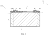
FIG. 3 is a cross-sectional view of a secondary battery; -
FIG. 4 is an exploded view of a secondary battery; -
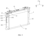
FIG. 5 is a schematic diagram of a secondary battery, in which a housing is omitted; -
FIG. 6 is a schematic diagram of an electrode assembly of a secondary battery before the electrode assembly is assembled with a current collecting member; -
FIG. 7 is a schematic diagram after an electrode assembly and a current collecting member are assembled; -
FIG. 8 is a schematic diagram of an embodiment of a current collecting member of a secondary battery; -
FIG. 9 is a vertical view of the current collecting member inFIG. 8 ; -
FIG. 10 is another schematic diagram of the current collecting member inFIG. 8 ; -
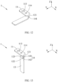
FIG. 11 is a schematic diagram of a plate used to form the current collecting member inFIG. 8 ; -
FIG. 12 is a schematic diagram of the plate inFIG. 11 after first bending; -
FIG. 13 is a schematic diagram of the plate inFIG. 12 after second bending; -
FIG. 14 is a schematic diagram of another embodiment of a current collecting member of a secondary battery; -
FIG. 15 is a vertical view of the current collecting member inFIG. 14 ; and -
FIG. 16 is a schematic diagram of a plate used to form the current collecting member inFIG. 14 . - To make the objectives, technical solutions, and advantages of this application more comprehensible, the following describes this application in detail with reference to embodiments and accompanying drawings. It should be understood that the specific embodiments described herein are merely used to explain this application but are not intended to limit this application.
- In the descriptions of this application, unless otherwise specified and defined explicitly, the terms "first", "second", and "third" are merely intended for a purpose of description, and should not be understood as any indication or implication of relative importance; the term "plurality of" indicates two or more (including two); and unless otherwise specified and defined explicitly, the term "connection" should be understood in its general senses. For example, the "connection" may be a fixed connection, a detachable connection, an integrated connection, or an electrical connection, or a signal connection; or may be a direct connection, or an indirect connection through an intermediate medium. A person of ordinary skill in the art can understand specific meanings of these terms in this application based on specific situations.
- In the descriptions of this application, the "perpendicular" not only includes absolute perpendicularity, but also includes the conventionally recognized perpendicularity in engineering, and therefore an error is allowed. The "parallel" not only includes absolute parallelism, but also includes the conventionally recognized parallelism in engineering, and therefore an error is allowed. It should be understood that the directional terms such as "up" and "down" described in the embodiments of this application are described as seen from the angles shown in the accompanying drawings, and should not be understood as a limitation to the embodiments of this application. This application is hereinafter further described in detail with reference to specific embodiments and accompanying drawings.
- This application provides an apparatus that uses a secondary battery as a power supply. The apparatus includes a main body and a
secondary battery 1000, where there are a plurality ofsecondary batteries 1000 disposed in the main body. Referring toFIG. 1 , the apparatus may be a steamship, a vehicle, or the like. The vehicle is a new energy vehicle, which may be a battery electric vehicle, or may be a hybrid electric vehicle or an extended-range electric vehicle. The main body of the vehicle is provided with a drive motor. The drive motor is electrically connected to thesecondary battery 1000, and is provided with electrical energy by thesecondary battery 1000. The drive motor is connected to wheels on the main body of the vehicle through a transmission mechanism to drive the vehicle. In some embodiments, thesecondary battery 1000 is a lithium-ion battery. - This application further provides a battery module. Referring to
FIG. 2 , the battery module includes a plurality ofsecondary batteries 1000, where the plurality ofsecondary batteries 1000 are arranged in sequence. The battery module may further include a support frame, where the support frame accommodates and fixes the plurality ofsecondary batteries 1000. - Referring to
FIG. 3 andFIG. 4 , the secondary battery includes acurrent collecting member 1, anelectrode assembly 2, ahousing 3, and atop cover assembly 4. - The
electrode assembly 2 is a core member of the secondary battery for implementing a charging and discharging function. Theelectrode assembly 2 includes a positive electrode plate, a negative electrode plate, and a separator, where the separator separates the positive electrode plate and the negative electrode plate. - The
electrode assembly 2 may be of a wound structure. Specifically, quantities of both the positive electrode plate and the negative electrode plate are one, and the positive electrode plate and the negative electrode plate are of a strip structure. The positive electrode plate, the separator, and the negative electrode plate are sequentially stacked and wound by two or more turns to form theelectrode assembly 2. In preparation of theelectrode assembly 2, theelectrode assembly 2 may be first wound to form a hollow cylindrical structure. After the winding, theelectrode assembly 2 is leveled to a plate shape. - Alternatively, the
electrode assembly 2 may alternatively be of a laminated structure. Specifically, there are a plurality of the positive electrode plates and a plurality of the negative electrode plates. The plurality of positive electrode plates and the negative electrode plates are alternately stacked, and the separator separates the positive electrode plates and the negative electrode plates. - The positive electrode plate includes a positive electrode current collector and a positive active material layer coated on a surface of the positive electrode current collector. The positive electrode current collector may be an aluminum foil, and the positive active material layer includes a ternary material, lithium manganate, or lithium iron phosphate. The positive electrode current collector includes a positive electrode coating region and a positive electrode blank region, where a surface of the positive electrode coating region is coated with the positive active material layer, and a surface of the positive electrode blank region is not coated with the positive active material layer.
- The negative electrode plate includes a negative electrode current collector and a negative active material layer coated on a surface of the negative electrode current collector. The negative electrode current collector may be a copper foil, and the negative active material layer includes graphite or silicon. The negative electrode current collector includes a negative electrode coating region and a negative electrode blank region, where a surface of the negative electrode coating region is coated with the negative active material layer, and a surface of the negative electrode blank region is not coated with the negative active material layer.
- From an appearance of the
electrode assembly 2, referring toFIG. 4 , theelectrode assembly 2 includes abase part 21 and atab 22 and thetab 22 extends from an end of thebase part 21 in a length direction X. There may be twotabs 22 extending from two ends of thebase part 21 in the length direction X, respectively. The twotabs 22 are a positive electrode tab and a negative electrode tab. Thebase part 21 includes the separator, the positive electrode coating region, and the negative electrode coating region. The positive electrode tab includes the positive electrode blank region, and the negative electrode tab includes the negative electrode blank region. - Referring to
FIG. 6 , thetab 22 has a multilayer structure. Specifically, eachtab 22 includes a plurality of tab layers stacked in a width direction Y - The
housing 3 may have a hexahedral shape or other shapes. An accommodating cavity is formed inside thehousing 3 to accommodate theelectrode assembly 2 and electrolyte. An end of thehousing 3 along a height direction Z forms an opening, and theelectrode assembly 2 can be placed into the accommodating cavity of thehousing 3 through the opening. Thehousing 3 may be made of a conductive metal material, and preferably, thehousing 3 is made of aluminum or aluminum alloy. - The
top cover assembly 4 includes atop cover plate 41 and anelectrode terminal 42, where thetop cover plate 41 is connected to thehousing 3, and theelectrode terminal 42 is disposed on thetop cover plate 41. A shape of thetop cover plate 41 matches that of the opening of thehousing 3, and thetop cover plate 41 may be connected to thehousing 3 through welding or the like to cover the opening of thehousing 3, thereby implementing sealing of thehousing 3. There are twoelectrode terminals 42, namely, a positive electrode terminal and a negative electrode terminal. The positive electrode terminal is electrically connected to the positive electrode tab, and the negative electrode terminal is electrically connected to the negative electrode tab. - There are two
current collecting members 1, one is connected to the positive electrode terminal and the positive electrode tab, and the other is connected to the negative electrode terminal and the negative electrode tab. - The following describes the current collecting member of this application in detail.
- Referring to
FIG. 4 to FIG. 10 , acurrent collecting member 1 of this application includes aterminal connection part 11, atransition part 12, and atab connection part 13. - The
terminal connection part 11 is perpendicular to a height direction Z. Theterminal connection part 11 may be connected to theelectrode terminal 42 through welding, riveting, or the like. In some embodiments, theterminal connection part 11 is plate-shaped, that is, in the height direction Z, theterminal connection part 11 has a uniform thickness. - The
transition part 12 is connected to theterminal connection part 11 and is bent to a side of theterminal connection part 11 along the height direction Z. In this application, thetransition part 12 is bent to the side of theterminal connection part 11 away from atop cover assembly 4 along the height direction Z. A connection between thetransition part 12 and theterminal connection part 11 extends along a first direction D, and the first direction D is inclined relative to a length direction X and a width direction Y - In this application, a dimension of the secondary battery along the length direction X is larger than a dimension of the secondary battery along the width direction Y
- The
tab connection part 13 is connected to thetransition part 12 and is bent relative to thetransition part 12, and a connection between thetransition part 12 and thetab connection part 13 is parallel to the length direction X. Along the height direction Y, thetab connection part 13 is located on a side of thetransition part 12 away from theterminal connection part 11. Thetab connection part 13 may be connected to atab 22 through welding or the like. - The
tab connection part 13 is at least partially perpendicular to the width direction Y In some embodiments, thetab connection part 13 is plate-shaped and is parallel to the length direction X. - The
current collecting member 1 of this application is formed by bending a metal plate. In some embodiments, the current collectingmember 1 is formed based on the following steps:
Referring toFIG. 11 , a strip-shaped metal plate is provided, where a dimension of the metal plate along the length direction X is larger than a dimension of the metal plate along the width direction Y - The metal plate is bent to form a
terminal connection part 11 and a flat plate part, where the flat plate part partially overlaps theterminal connection part 11 in the height direction Z, where a bending part of the metal plate is inclined relative to the length direction X and the width direction Y - The flat plate part is bent downward along the height direction Z, and the
transition part 12 and thetab connection part 13 are formed after the bending. Thetab connection part 13 is perpendicular to theterminal connection part 11, thetransition part 12 is connected between theterminal connection part 11 andtab connection part 13, and a connection between thetransition part 12 and thetab connection part 13 is parallel to the length direction X. - Before the
electrode assembly 2 and the current collectingmember 1 are assembled, thetab 22 is substantially parallel to the length direction X. If thetab connection part 13 is perpendicular to the length direction X, when theelectrode assembly 2 and the current collectingmember 1 are assembled, only thetab 22 can be bent, or an end of thetab 22 away from abase part 21 is connected to thetab connection part 13. Bending thetab 22 increases processes and reduces assembly efficiency. In addition, thetab 22 is a metal foil, and therefore a thickness of each tab layer of thetab 22 is small. Connecting an end of each tab layer to thetab connection part 13 results in low connection strength and a small flow area. - However, a bending structure of the current collecting
member 1 of this application can make at least a portion of thetab connection part 13 perpendicular to the width direction Y, and thetab 22 can be directly attached to the portion of thetab connection part 13 perpendicular to the width direction Y without bending, thereby reducing assembly difficulty. In addition, a plurality of tab layers of thetab 22 can be laminated on thetab connection part 13, to increase a connection area between each tab layer and thetab connection part 13, enhance connection strength between thetab connection part 13 and thetab 22, and improve a flow capacity. - In some embodiments, referring to
FIG. 9 , in the width direction Y, afirst edge 111 and asecond edge 112 are oppositely arranged on two ends of theterminal connection part 11. Thefirst edge 111 and thesecond edge 112 are parallel to the length direction X. In a plane perpendicular to the height direction Z, along the width direction Y, a projection of thetab connection part 13 is at least partially located between a projection of thefirst edge 111 and a projection of thesecond edge 112. This can reduce an additional space occupied by thetab connection part 13 in the width direction Y, reduce a maximum dimension of the current collectingmember 1 in the width direction Y, reduce a space occupied by the current collectingmember 1 in thehousing 3, and improve an energy density of the secondary battery. - In some embodiments, referring to
FIG 8 to FIG. 10 , thetransition part 12 includes afirst bending part 121, an adaptingpart 122, and asecond bending part 123, where the adaptingpart 122 is located on a lower side of theterminal connection part 11 along the height direction Z, thefirst bending part 121 is connected between theterminal connection part 11 and the adaptingpart 122 and is parallel to the first direction D, and thesecond bending part 123 is connected between thetab connection part 13 and the adaptingpart 122 and is parallel to the length direction X. Thefirst bending part 121 and thesecond bending part 123 are respectively formed in two bending processes of the current collectingmember 1, and an outer surface of thefirst bending part 121 and an outer surface of thesecond bending part 123 are generally arc. - In a plane perpendicular to the height direction Z, along the width direction Y, a projection of the
second bending part 123 is at least partially located between the projection of thefirst edge 111 and the projection of thesecond edge 112. This can reduce an additional space occupied by thetransition part 12 in the width direction Y, reduce a maximum dimension of the current collectingmember 1 in the width direction Y, reduce a space occupied by the current collectingmember 1 in thehousing 3, and improve an energy density of the secondary battery. - The adapting
part 122 is located on an inner side thesecond bending part 123 in the width direction Y In a plane perpendicular to the height direction Z, along the width direction Y, the adaptingpart 122 is located between the projection of thefirst edge 111 and the projection of thesecond edge 112. In other words, the adaptingpart 122 does not occupy an additional space in the width direction Y - In some embodiments, the adapting
part 122 is parallel to theterminal connection part 11. In this way, a gap between the adaptingpart 122 and theterminal connection part 11 can be reduced, and the dimension of the current collectingmember 1 in the height direction Z can be reduced. Further preferably, the adaptingpart 122 contacts theterminal connection part 11; during charging and discharging, a current can be directly transmitted to theterminal connection part 11 through the adaptingpart 122, thereby increasing the flow area between thetransition part 12 and theterminal connection part 121, and improving a flow capacity of the current collectingmember 1. - In some embodiments, referring to
FIG. 8 to FIG. 10 , the current collectingmember 1 has afirst notch 14. Thefirst notch 14 has a first sub-notch 141 and a second sub-notch 142, and the first sub-notch 141 and the second sub-notch 142 are communicated with each other. - The first sub-notch 141 is located on a side of the
first bending part 121 close to thetab connection part 13 along the first direction D, an included angle between the first direction D and the width direction Y is α, a dimension of theterminal connection part 11 along the width direction Y is L, and a dimension of thefirst bending part 121 along the first direction D is less than L/cos α. By opening the first sub-notch 141, the dimension of thefirst bending part 121 along the first direction D can be reduced, so that an end of thefirst bending part 121 close to thetab connection part 13 in the first direction D tapers inwards. The end of thefirst bending part 121 close to thetab connection part 13 in the first direction D directly affects a position of thesecond bending part 123 in the width direction Y When thefirst bending part 121 tapers inwards along the first direction D near an end of thetab connection part 13, the space occupied by thesecond bending part 123 and thetab connection part 13 in the width direction Y can be reduced. - In a preferred embodiment, the
first bending part 121 and thetab connection part 13 do not occupy an additional space in the width direction Y In other words, in a plane perpendicular to the height direction Z, along the width direction Y, neither a projection of thesecond bending part 123 nor a projection oftab connection part 13 goes beyond the projection of thefirst edge 111 or the projection of thesecond edge 112. - The second sub-notch 142 is located on a side of the
second bending part 123 along the length direction X. Along the length direction X, a dimension of thetab connection part 13 is larger than a dimension of thesecond bending part 123. By opening the second sub-notch 142, the dimension of thesecond bending part 123 can be reduced, bending difficulty of thesecond bending part 123 can be reduced, and thesecond bending part 123 is prevented from interfering with thefirst bending part 121 in a bending process. - The included angle α between the first direction D and the width direction Y is 40 degrees to 50 degrees. Preferably, the included angle α between the first direction D and the width direction Y is 45 degrees. In this way, referring to
FIG. 13 , when the current collectingmember 1 is bent and formed, thetab connection part 13 can be substantially parallel to the height direction Z, avoiding thetab connection part 13 being inclined relative to the height direction Z, and reducing the space occupied by thetab connection part 13. Certainly, due to a process error, the included angle α between the first direction D and the width direction Y is 45±5 degrees. - The following briefly describes a method for manufacturing a
current collecting member 1 in other embodiments. Specifically, the manufacturing method includes the following steps. - Referring to
FIG. 11 , a metal plate is provided, where a dimension of the metal plate along a length direction X is larger than a dimension of the metal plate in a width direction Y, and the metal plate includes a first long side and a second long side that are oppositely arranged in the width direction Y - A
first notch 14 is opened on the first long side of the metal plate. Thefirst notch 14 may be formed by punching or the like, and thefirst notch 14 may be rectangular, trapezoidal, triangular, semicircular, or the like. - Referring to
FIG. 12 , the metal plate is bent in a region in which thefirst notch 14 is opened, and aterminal connection part 11, a flat plate part, and afirst bending part 121 are formed, where the flat plate part partially overlaps theterminal connection part 11 in a height direction Z, thefirst bending part 121 connects theterminal connection part 11 and the flat plate part, and thefirst bending part 121 extends along a first direction D inclined relative to the length direction X and the width direction Y - After the metal plate is bent, a first sub-notch 141 and a second sub-notch 142 that are communicated with each other are formed at the
first notch 14. The first sub-notch 141 is opened on thefirst bending part 121. To be specific, the first sub-notch 141 is opened on a side of thefirst bending part 121 along the first direction D. The second sub-notch 142 is opened on the flat plate part. To be specific, the second sub-notch 142 is located on a side of a partial region of the flat plate part along the length direction X. - In a region in which the second sub-notch 142 is opened, the flat plate part is bent along the height direction Z, and an adapting
part 122, atab connection part 13, and thesecond bending part 123 are formed after the bending. The adaptingpart 122 is located on a lower side of theterminal connection part 11 along the height direction Z, thetab connection part 13 is perpendicular to the adaptingpart 122, and thesecond bending part 123 is connected between the adaptingpart 122 and thetab connection part 13 and is parallel to the length direction X. - In this application, by opening the
first notch 14, after the current collectingmember 1 is bent and formed, the additional space occupied by thetransition part 12 and thetab connection part 13 in the width direction Y can be reduced, the maximum dimension of the current collectingmember 1 in the width direction Y can be reduced, and the space occupied by the current collectingmember 1 in thehousing 3 can be reduced. - In some embodiments, referring to
FIG. 14 and FIG. 15 , the current collectingmember 1 further has asecond notch 15, where thesecond notch 15 is at least partially located on a side of thefirst bending part 121 away from thetab connection part 13 along the first direction D. - By opening the
second notch 15, the dimension of thefirst bending part 121 along the first direction D can be reduced, so that an end of thefirst bending part 121 away from thetab connection part 13 in the first direction D tapers inwards. When the end of thefirst bending part 121 away from thetab connection part 13 in the first direction D tapers inwards, the additional space occupied by thefirst bending part 121 in the width direction Y can be reduced. - A maximum dimension of the
terminal connection part 11 in the width direction Y is a maximum dimension of the current collectingmember 1 in the width direction Y In other words, in a plane perpendicular to the height direction Z, along the width direction Y, neither a projection of thetransition part 12 nor a projection oftab connection part 13 goes beyond the projection of thefirst edge 111 or the projection of thesecond edge 112. In this case, neither thetransition part 12 nor thetab connection part 13 occupies the additional space in the width direction Y, thereby reducing the space occupied by the current collectingmember 1 in thehousing 3, and improving an energy density of the secondary battery. - The following briefly describes a method for manufacturing a
current collecting member 1 in still other embodiments. Specifically, the manufacturing method includes the following steps. - Referring to
FIG. 11 , a metal plate is provided, where a dimension of the metal plate along a length direction X is larger than a dimension of the metal plate in a width direction Y, and the metal plate includes a first long side and a second long side that are oppositely arranged in the width direction Y - A
first notch 14 is opened on the first long side of the metal plate, and asecond notch 15 is opened on the second long side of the metal plate. Thefirst notch 14 and thesecond notch 15 may be formed in a same punching process, or may be formed in two punching processes, respectively. - Referring to
FIG. 12 , the metal plate is bent in a region in which thefirst notch 14 is opened, and aterminal connection part 11, a flat plate part, and afirst bending part 121 are formed, where the flat plate part partially overlaps theterminal connection part 11 in a height direction Z, thefirst bending part 121 connects theterminal connection part 11 and the flat plate part, and thefirst bending part 121 extends along a first direction D inclined relative to the length direction X and the width direction Y - After the metal plate is bent, a first sub-notch 141 and a second sub-notch 142 that are communicated with each other are formed at the first notch. The first sub-notch 141 is opened on the
first bending part 121. To be specific, the first sub-notch 141 is opened on a side of thefirst bending part 121 along the first direction D. The second sub-notch 142 is opened on the flat plate part. To be specific, the second sub-notch 142 is located on a side of a partial region of the flat plate part along the length direction X. Thesecond notch 15 is at least partially located on a side of thefirst bending part 121 away from thetab connection part 13 along the first direction D. - In a region in which the second sub-notch 142 is opened, the flat plate part is bent along the height direction Z, and an adapting
part 122, atab connection part 13, and thesecond bending part 123 are formed after the bending. The adaptingpart 122 is located on a lower side of theterminal connection part 11 along the height direction Z, thetab connection part 13 is perpendicular to the adaptingpart 122, and thesecond bending part 123 is connected between the adaptingpart 122 and thetab connection part 13 and is parallel to the length direction X. - A dimension of the
terminal connection part 11 in the width direction Y is equal to a dimension of thetab connection part 13 in the length direction X. In this case, the current collectingmember 1 of this application can be formed by a metal plate with equal widths through processes such as notch punching and bending. - In some embodiments, referring to
FIG. 5 to FIG. 7 , thetab 22 is arranged on a side of thetab connection part 13 along the width direction Y - The
tab connection part 13 includes afirst part 131 and asecond part 132, where thefirst part 131 is perpendicular to the width direction, thesecond part 132 is connected between thefirst part 131 and atransition part 12, and thesecond part 132 is inclined relative to thefirst part 131 toward a direction away from thetab 22. In a plane perpendicular to the height direction Z, a projection of thefirst part 131 at least partially overlaps a projection of thetransition part 12. - The
tab 22 includes a fixingpart 221 and aconvex part 222, where the fixingpart 221 is connected to thefirst part 131, and theconvex part 222 is connected to the fixingpart 221 and is located on a side of the fixingpart 221 close to thetransition part 12. The fixingpart 221 may be connected to thefirst part 131 through welding or the like. - Referring to
FIG. 6 , thetab 22 is of a multi-layer structure, a plurality of tab layers of thetab 22 are gathered together in a middle region along the height direction Z and is connected to thefirst part 131, and the gathered middle region forms the fixingpart 221. Aconvex part 222 is formed in an end region of the plurality of tab layers of thetab 22 in the height direction Z. - The end region of the plurality of tab layers of the
tab 22 along the height direction Z is not gathered. Therefore, along the width direction Y, a dimension of theconvex part 222 is larger than a dimension of the fixingpart 221. - The
second part 132 is inclined relative to thefirst part 131 toward a direction away from thetab 22, and therefore thesecond part 132 can reserve a specific space for theconvex part 222 to accommodate theconvex part 222 with a larger dimension. In this case, in the height direction Z, a portion of theconvex part 222 is located between thesecond part 132 and thetransition part 12. - In some embodiments, the
tab connection part 13 further includes athird part 133, where thethird part 133 is connected between thesecond part 132 and thetransition part 12, and thethird part 133 is perpendicular to the width direction Y In a plane perpendicular to the width direction Y, a projection of thethird part 133 at least partially overlaps a projection of theconvex part 222. By providing thethird part 133, a degree of inclination of thesecond part 132 relative to thefirst part 131 can be increased, and more space is reserved for theconvex part 222. - Referring to
FIG. 13 andFIG. 8 , after thetab connection part 13 of a plate-shaped is formed, by bending thetab connection part 13 twice, thefirst part 131 that is perpendicular to the adaptingpart 122, thethird part 133 that is parallel to thefirst part 131 and that is connected to thesecond bending part 123, and asecond part 132 that connects thefirst part 131 and thethird part 133 and that is inclined relative to thefirst part 131 can be formed. - In some embodiments, referring to
FIG. 3 to FIG. 8 , theterminal connection part 11 has a first throughhole 113 and a second throughhole 114, where the first throughhole 113 and the second throughhole 114 are arranged along the length direction X. - The
top cover 41 has a terminal hole, and the first throughhole 113 is provided on a lower side of the terminal hole. Theelectrode terminal 42 has a flange part and an extension part, where the flange part supports theterminal connection part 11 from the lower side, and the extension part extends from the flange part, passes through the first throughhole 113 and the terminal hole, and extends outside of the top cover plate. - The
top cover assembly 4 further includes alower insulator 43, where thelower insulator 43 is arranged on thetop cover plate 41 and separates thetop cover plate 41 from the current collectingmember 1. Thelower insulator 43 has aprotrusion 431, where theprotrusion 431 is inserted into the second throughhole 114. Theprotrusion 431 can prevent the current collectingmember 1 from rotating along theelectrode terminal 42. - Referring to
FIG. 11 to FIG. 13 , this application also provides a method for manufacturing a current collecting member, including: - providing a metal plate, where the metal plate includes a first long side and a second long side that are arranged oppositely in a width direction Y;
- opening a
first notch 14 on the first long side of the metal plate; - bending the metal plate in a region in which the
first notch 14 is opened, and forming aterminal connection part 11, a flat plate part partially overlapping theterminal connection part 11 along a height direction Z, afirst bending part 121 connecting theterminal connection part 11 and the flat plate part, where thefirst bending part 121 extends along a first direction D inclined relative to a length direction X and the width direction Y; - after bending the metal plate, forming, at the
first notch 14, at least a first sub-notch 141 and a second sub-notch 142 that are communicated with each other, where the first sub-notch 141 is opened in a side of thefirst bending part 121 along the first direction D, and at least a portion of the second sub-notch 142 is opened on a side of the flat plate part along the length direction X; and - in a region in which the second sub-notch 142 is opened, bending the flat plate part along the height direction Z, and after the bending, forming an adapting
part 122 located on a lower side of theterminal connection part 11 along the height direction Z, atab connection part 13 perpendicular to the adaptingpart 122, and asecond bending part 123 that is connected between the adaptingpart 122 and thetab connection part 13 and that is parallel to the length direction X. - In this application, by opening the
first notch 14, after the current collectingmember 1 is bent and formed, the additional space occupied by thetransition part 12 and thetab connection part 13 in the width direction Y can be reduced, the maximum dimension of the current collectingmember 1 in the width direction Y can be reduced, and the space occupied by the current collectingmember 1 in thehousing 3 can be reduced. - The method for manufacturing a current collecting member in this application further includes: opening a
second notch 15 on the second long side of the metal plate, where thefirst notch 14 and thesecond notch 15 are respectively located on two sides of the metal plate along the width direction Y; after opening thefirst notch 14 and thesecond notch 15, bending the metal plate in a region in which thefirst notch 14 is opened, where after the metal plate is bent and thefirst bending part 121 is formed, thesecond notch 15 is at least partially located on a side of thefirst bending part 121 away from thetab connection part 13 along the first direction. - By opening the
second notch 15, the dimension of thefirst bending part 121 along the first direction D can be reduced, so that an end of thefirst bending part 121 away from thetab connection part 13 in the first direction D tapers inwards. When the end of thefirst bending part 121 away from thetab connection part 13 in the first direction D tapers inwards, the additional space occupied by thefirst bending part 121 in the width direction Y can be reduced. - The method for manufacturing a current collecting member in this application further includes: after the
tab connection part 13 is formed, bending thetab connection part 13 to form afirst part 131 perpendicular to the adaptingpart 122, athird part 133 that is parallel to thefirst part 131 and that is connected to thesecond bending part 123, and asecond part 132 that connects thefirst part 131 and thethird part 133 and that is inclined relative to thefirst part 131. - The bent
tab connection part 13 can reserve a specific space for theconvex part 222 to accommodate theconvex part 222 with a larger dimension. - This application further provides a method for manufacturing a secondary battery, including:
- providing a
current collecting member 1 manufactured according to the method for manufacturing a current collecting member; - connecting a
terminal connection part 11 of the current collectingmember 1 to anelectrode terminal 42 of atop cover assembly 4, and connecting atab connection part 13 of the current collectingmember 1 to atab 22 of anelectrode assembly 2; and - placing the
electrode assembly 2 into ahousing 3, and connecting atop cover plate 41 of thetop cover assembly 4 and thehousing 3 in a sealed manner.
| 1. | current collecting member; | 2. | electrode assembly; |
| 11. | terminal connection part; | 21. | base part; |
| 111. | first edge; | 22. | tab; |
| 112. | second edge; | 221. | fixing part; |
| 113: | first through hole; | 222. | convex part; |
| 114: | second through hole; | 3. | housing; |
| 12. | transition part; | 4. | top cover assembly; |
| 121. | first bending part; | 41. | top cover plate; |
| 122. | adapting part; | 42. | electrode terminal; |
| 123. | second bending part; | 43. | lower insulator; |
| 13. | tab connection part; | 431. | protrusion; |
| 131. | first part; | 1000. | secondary battery; |
| 132. | second part; | D. | first direction; |
| 133. | third part; | X. | length direction; |
| 14. | first notch; | Y | width direction; |
| 141. | first sub-notch; | Z. | height direction; |
| 142. | second sub-notch; and | ||
| 15. | second notch. |
Claims (12)
- Secondary battery, comprising: a top cover assembly (4), an electrode assembly (2), a housing (3), and a current collecting member (1), whereinthe electrode assembly (2) is accommodated in the housing (3), and the electrode assembly (2) comprises a base part (21) and a tab (22), wherein the tab (22) extends from an end of the base part (21) in the length direction (X), the tab (22) has a multilayer structure and the tab (22) includes a plurality of tab layers stacked in a width direction (Y);the top cover assembly (4) comprises a top cover plate (41) and an electrode terminal (42), wherein the top cover plate (41) is connected to the housing (3), and the electrode terminal (42) is disposed on the top cover plate (41);a terminal connection part (11) of the current collecting member (1) is connected to the electrode terminal (42), and the tab connection part (13) of the current collecting member (1) is connected to the tab (22); andthe current collecting member (1) of the secondary battery is formed by bending a strip-shaped metal plate and comprises a terminal connection part (11), a transition part (12), and a tab connection part (13), whereinthe terminal connection part (11) is perpendicular to a height direction (Z);the transition part (12) is connected to the terminal connection part (11) and is bent to a side of the terminal connection part (11) along the height direction (Z), a connection between the transition part (12) and the terminal connection part (11) extends along a first direction (D), and the first direction (D) is inclined relative to a length direction (X) and a width direction (Y);the tab connection part (13) is connected to the transition part (12) and is bent relative to the transition part (12), and a connection between the transition part (12) and the tab connection part (13) is parallel to the length direction (X);the tab connection part (13) is at least partially perpendicular to the width direction (Y); andalong the height direction (Z), the tab connection part (13) is located on a side of the transition part (12) away from the terminal connection part (11);wherein in the width direction (Y), a first edge (111) and a second edge (112) are oppositely arranged on two ends of the terminal connection part (11);in a plane perpendicular to the height direction (Z), along the width direction (Y), a projection of the tab connection part (13) is at least partially located between a projection of the first edge (111) and a projection of the second edge (112); andthe transition part (12) comprises a first bending part (121), an adapting part (122), and a second bending part (123), wherein the adapting part (122) is located on a lower side of the terminal connection part (11) along the height direction (Z), the first bending part (121) is connected between the terminal connection part (11) and the adapting part (122) and is parallel to the first direction (D), and the second bending part (123) is connected between the tab connection part (13) and the adapting part (122) and is parallel to the length direction (X); andin a plane perpendicular to the height direction (Z), along the width direction (Y), a projection of the second bending part (123) is at least partially located between the projection of the first edge (111) and the projection of the second edge (112).
- Secondary battery according to claim 1, wherein the adapting part (122) is parallel to the terminal connection part (11).
- Secondary battery according to claim 1, whereinthe current collecting member (1) has a first notch (14), the first notch (14) has a first sub-notch (141) and a second sub-notch (142), and the first sub-notch (141) and the second sub-notch (142) are communicated with each other, whereinthe first sub-notch (141) is located on a side of the first bending part (121) close to the tab connection part (13) along the first direction (D), an included angle between the first direction (D) and the width direction (Y) is α, a dimension of the terminal connection part (11) along the width direction (Y) is L, and a dimension of the first bending part (121) along the first direction (D) is less than L/cos α;the second sub-notch (142) is located on a side of the second bending part (123) along the length direction (X); andalong the length direction (X), a dimension of the tab connection part (13) is larger than a dimension of the second bending part (123).
- Secondary battery according to claim 3, wherein the included angle between the first direction (D) and the width direction (Y) is 40 degrees to 50 degrees.
- Secondary battery according to claim 3, wherein the current collecting member (1) further has a second notch (15), and the second notch (15) is at least partially located on a side of the first bending part (121) away from the tab connection part (13) along the first direction (D).
- Secondary battery according to claim 5, wherein a maximum dimension of the terminal connection part (11) in the width direction (Y) is a maximum dimension of the current collecting member (1) in the width direction (Y).
- Secondary battery according to any one of claims 1 to 6, wherein a dimension of the terminal connection part (11) in the width direction (Y) is a dimension of the tab connection part (13) in the length direction (X).
- Secondary battery according to any one of claims 1 to 7, whereinthe tab (22) is arranged on a side of the tab connection part (13) along the width direction (Y);the tab connection part (13) comprises a first part (131) and a second part (132), wherein the first part (131) is perpendicular to the width direction (Y), the second part (132) is connected between the first part (131) and a transition part (12), and the second part (132) is inclined relative to the first part (131) toward a direction away from the tab (22);in a plane perpendicular to the height direction (Z), a projection of the first part (131) at least partially overlaps a projection of the transition part (12);the tab (22) comprises a fixing part (221) and a convex part (222), wherein the fixing part (221) is connected to the first part (131), and the convex part (222) is connected to the fixing part (221) and is located on a side of the fixing part (221) close to the transition part (12); andalong the width direction (Y), a dimension of the convex part (222) is larger than a dimension of the fixing part (221); and in the height direction (Z), a portion of the convex part (222) is located between the second part (132) and the transition part (12).
- Secondary battery according to claim 8, whereinthe tab connection part (13) comprises a third part (133), wherein the third part (133) is connected between the second part (132) and the transition part (12), and the third part (133) is perpendicular to the width direction (Y); andin a plane perpendicular to the width direction (Y), a projection of the third part (133) at least partially overlaps a projection of the convex part (222).
- Secondary battery according to any one of claims 1 to 7, whereinthe terminal connection part (11) has a first through hole (113) and a second through hole (114), wherein the first through hole (113) and the second through hole (114) are arranged along the length direction (X);the electrode terminal (42) passes through the first through hole (113);the top cover assembly (4) further comprises a lower insulator (43), wherein the lower insulator (43) is arranged on the top cover plate (41) and separates the top cover plate (41) from the current collecting member (1); andthe lower insulator (43) has a protrusion (431), wherein the protrusion (431) is inserted into the second through hole (114).
- Battery module, comprising the secondary battery according to any one of claims 1 to 10, wherein there are a plurality of secondary batteries.
- Apparatus, comprising a main body and the secondary battery according to any one of claims 1 to 10, wherein there are a plurality of secondary batteries disposed in the main body.
Applications Claiming Priority (1)
| Application Number | Priority Date | Filing Date | Title |
|---|---|---|---|
| PCT/CN2019/122647 WO2021108980A1 (en) | 2019-12-03 | 2019-12-03 | Current collecting member and manufacturing method therefor, secondary battery and manufacturing method therefor, battery module, and device |
Publications (3)
| Publication Number | Publication Date |
|---|---|
| EP3926751A1 EP3926751A1 (en) | 2021-12-22 |
| EP3926751A4 EP3926751A4 (en) | 2022-04-27 |
| EP3926751B1 true EP3926751B1 (en) | 2023-06-14 |
Family
ID=76221318
Family Applications (1)
| Application Number | Title | Priority Date | Filing Date |
|---|---|---|---|
| EP19954959.3A Active EP3926751B1 (en) | 2019-12-03 | 2019-12-03 | Secondary battery with specific current collecting member, battery module and device |
Country Status (5)
| Country | Link |
|---|---|
| US (1) | US20220085465A1 (en) |
| EP (1) | EP3926751B1 (en) |
| JP (1) | JP7411087B2 (en) |
| CN (1) | CN114144934B (en) |
| WO (1) | WO2021108980A1 (en) |
Citations (1)
| Publication number | Priority date | Publication date | Assignee | Title |
|---|---|---|---|---|
| WO2012077216A1 (en) * | 2010-12-09 | 2012-06-14 | 日立ビークルエナジー株式会社 | Secondary battery |
Family Cites Families (17)
| Publication number | Priority date | Publication date | Assignee | Title |
|---|---|---|---|---|
| GB1422782A (en) * | 1972-04-06 | 1976-01-28 | Alkaline Batteries Ltd | Alkaline electric cells |
| KR101049833B1 (en) * | 2009-06-23 | 2011-07-15 | 에스비리모티브 주식회사 | Secondary battery |
| JP5656592B2 (en) * | 2010-12-06 | 2015-01-21 | 日立オートモティブシステムズ株式会社 | Secondary battery |
| JP2012182043A (en) * | 2011-03-02 | 2012-09-20 | Auto Network Gijutsu Kenkyusho:Kk | Bus bar |
| JP2013127948A (en) * | 2011-11-17 | 2013-06-27 | Gs Yuasa Corp | Collector, electricity storage element and method for manufacturing collector |
| US20140023913A1 (en) * | 2012-07-17 | 2014-01-23 | Sanyo Electric Co., Ltd. | Prismatic secondary battery |
| KR20140124247A (en) * | 2013-04-16 | 2014-10-24 | 삼성에스디아이 주식회사 | Rechargeable battery |
| JP6733175B2 (en) | 2015-12-28 | 2020-07-29 | 株式会社Gsユアサ | Storage element |
| US11289746B2 (en) * | 2016-05-03 | 2022-03-29 | Bosch Battery Systems Llc | Cooling arrangement for an energy storage device |
| JP6870316B2 (en) | 2016-12-21 | 2021-05-12 | 三洋電機株式会社 | Square secondary battery and its manufacturing method |
| KR101928073B1 (en) * | 2016-12-27 | 2018-12-11 | 주식회사 유라코퍼레이션 | Connecting structure of bus-bar assembly |
| CN207068966U (en) * | 2017-06-23 | 2018-03-02 | 潍坊力神动力电池系统有限公司 | A kind of power battery module is flexible coupling component |
| KR102571487B1 (en) * | 2017-08-31 | 2023-08-28 | 삼성에스디아이 주식회사 | Secondary Battery And Assembling Method thereof |
| CN208014793U (en) * | 2018-01-16 | 2018-10-26 | 宁德时代新能源科技股份有限公司 | Connecting elements and rechargeable battery |
| CN207801088U (en) * | 2018-01-31 | 2018-08-31 | 宁德时代新能源科技股份有限公司 | Bus-bar and battery modules |
| CN208507745U (en) * | 2018-07-13 | 2019-02-15 | 宁德时代新能源科技股份有限公司 | Secondary cell |
| CN209675387U (en) * | 2019-05-10 | 2019-11-22 | 昆山长盈精密技术有限公司 | Electrode protective jacket |
-
2019
- 2019-12-03 EP EP19954959.3A patent/EP3926751B1/en active Active
- 2019-12-03 JP JP2022533192A patent/JP7411087B2/en active Active
- 2019-12-03 WO PCT/CN2019/122647 patent/WO2021108980A1/en unknown
- 2019-12-03 CN CN201980098700.XA patent/CN114144934B/en active Active
-
2021
- 2021-11-19 US US17/530,759 patent/US20220085465A1/en active Pending
Patent Citations (1)
| Publication number | Priority date | Publication date | Assignee | Title |
|---|---|---|---|---|
| WO2012077216A1 (en) * | 2010-12-09 | 2012-06-14 | 日立ビークルエナジー株式会社 | Secondary battery |
Also Published As
| Publication number | Publication date |
|---|---|
| CN114144934A (en) | 2022-03-04 |
| JP2023504667A (en) | 2023-02-06 |
| EP3926751A1 (en) | 2021-12-22 |
| JP7411087B2 (en) | 2024-01-10 |
| US20220085465A1 (en) | 2022-03-17 |
| CN114144934B (en) | 2024-03-15 |
| WO2021108980A1 (en) | 2021-06-10 |
| EP3926751A4 (en) | 2022-04-27 |
Similar Documents
| Publication | Publication Date | Title |
|---|---|---|
| KR100637443B1 (en) | Secondary battery and terminal assembly using the same | |
| US7364817B2 (en) | Secondary battery and method of manufacturing the same | |
| US20050221178A1 (en) | Electrode package and secondary battery using the same | |
| JP2006019284A (en) | Secondary battery | |
| EP2602845B1 (en) | Secondary battery comprising electrode leads coated with a corrosion-preventing protective layer | |
| US8021781B2 (en) | Jelly-roll type electrode assembly and secondary battery employing the same | |
| WO2022228091A1 (en) | Lithium battery and preparation method therefor | |
| US20230361355A1 (en) | Cell, Method for Manufacturing Cell, and Battery | |
| JP2010525552A (en) | Electrochemical unit cell and energy storage device with welding point connection | |
| KR100612236B1 (en) | Secondary battery and electrodes assembly | |
| CN217768705U (en) | Pole piece structure, electric core subassembly, battery monomer, battery and power consumption device | |
| US20220367985A1 (en) | Electrode assembly, battery cell, battery, electrical apparatus, and manufacturing method and device | |
| EP3926751B1 (en) | Secondary battery with specific current collecting member, battery module and device | |
| US20220247043A1 (en) | Battery cell, battery, power consumption device and battery cell manufaturing method and device | |
| WO2023138416A1 (en) | Battery cell and manufacturing method therefor, battery, and power consuming device | |
| KR20120123851A (en) | Electrode assembly including anode and cathod electrode more than 2 and electrochemical device using the same | |
| CN114361732A (en) | Electrochemical device and electronic apparatus | |
| KR20080028091A (en) | Rechargeabel battery | |
| KR100528902B1 (en) | Secondary battery and fabrication method thereof | |
| US20240088447A1 (en) | Electrode assembly, battery cell, battery and electrical device | |
| EP4258445A1 (en) | Battery, electrical device, and method and device for preparing battery | |
| WO2023133859A1 (en) | Battery cell and manufacturing method therefor, device, battery, and electric apparatus | |
| EP4037088A2 (en) | Electrode terminal and use thereof | |
| CN220527148U (en) | Battery core package, battery module and battery package | |
| WO2024016447A1 (en) | Current collector, electrode sheet, battery cell, hot-pressing mold, battery, and electric device |
Legal Events
| Date | Code | Title | Description |
|---|---|---|---|
| STAA | Information on the status of an ep patent application or granted ep patent |
Free format text: STATUS: THE INTERNATIONAL PUBLICATION HAS BEEN MADE |
|
| PUAI | Public reference made under article 153(3) epc to a published international application that has entered the european phase |
Free format text: ORIGINAL CODE: 0009012 |
|
| STAA | Information on the status of an ep patent application or granted ep patent |
Free format text: STATUS: REQUEST FOR EXAMINATION WAS MADE |
|
| 17P | Request for examination filed |
Effective date: 20210913 |
|
| AK | Designated contracting states |
Kind code of ref document: A1 Designated state(s): AL AT BE BG CH CY CZ DE DK EE ES FI FR GB GR HR HU IE IS IT LI LT LU LV MC MK MT NL NO PL PT RO RS SE SI SK SM TR |
|
| A4 | Supplementary search report drawn up and despatched |
Effective date: 20220324 |
|
| RIC1 | Information provided on ipc code assigned before grant |
Ipc: H01M 50/567 20210101ALI20220319BHEP Ipc: H01M 50/557 20210101ALI20220319BHEP Ipc: H01M 50/548 20210101ALI20220319BHEP Ipc: H01M 50/166 20210101ALI20220319BHEP Ipc: H01M 50/103 20210101ALI20220319BHEP Ipc: H01M 50/531 20210101AFI20220319BHEP |
|
| STAA | Information on the status of an ep patent application or granted ep patent |
Free format text: STATUS: EXAMINATION IS IN PROGRESS |
|
| 17Q | First examination report despatched |
Effective date: 20220818 |
|
| GRAP | Despatch of communication of intention to grant a patent |
Free format text: ORIGINAL CODE: EPIDOSNIGR1 |
|
| STAA | Information on the status of an ep patent application or granted ep patent |
Free format text: STATUS: GRANT OF PATENT IS INTENDED |
|
| INTG | Intention to grant announced |
Effective date: 20230127 |
|
| DAV | Request for validation of the european patent (deleted) | ||
| DAX | Request for extension of the european patent (deleted) | ||
| GRAS | Grant fee paid |
Free format text: ORIGINAL CODE: EPIDOSNIGR3 |
|
| GRAA | (expected) grant |
Free format text: ORIGINAL CODE: 0009210 |
|
| STAA | Information on the status of an ep patent application or granted ep patent |
Free format text: STATUS: THE PATENT HAS BEEN GRANTED |
|
| AK | Designated contracting states |
Kind code of ref document: B1 Designated state(s): AL AT BE BG CH CY CZ DE DK EE ES FI FR GB GR HR HU IE IS IT LI LT LU LV MC MK MT NL NO PL PT RO RS SE SI SK SM TR |
|
| REG | Reference to a national code |
Ref country code: CH Ref legal event code: EP |
|
| P01 | Opt-out of the competence of the unified patent court (upc) registered |
Effective date: 20230516 |
|
| REG | Reference to a national code |
Ref country code: DE Ref legal event code: R096 Ref document number: 602019031219 Country of ref document: DE |
|
| REG | Reference to a national code |
Ref country code: AT Ref legal event code: REF Ref document number: 1579908 Country of ref document: AT Kind code of ref document: T Effective date: 20230715 |
|
| REG | Reference to a national code |
Ref country code: LT Ref legal event code: MG9D |
|
| REG | Reference to a national code |
Ref country code: NL Ref legal event code: MP Effective date: 20230614 |
|
| PG25 | Lapsed in a contracting state [announced via postgrant information from national office to epo] |
Ref country code: SE Free format text: LAPSE BECAUSE OF FAILURE TO SUBMIT A TRANSLATION OF THE DESCRIPTION OR TO PAY THE FEE WITHIN THE PRESCRIBED TIME-LIMIT Effective date: 20230614 Ref country code: NO Free format text: LAPSE BECAUSE OF FAILURE TO SUBMIT A TRANSLATION OF THE DESCRIPTION OR TO PAY THE FEE WITHIN THE PRESCRIBED TIME-LIMIT Effective date: 20230914 Ref country code: ES Free format text: LAPSE BECAUSE OF FAILURE TO SUBMIT A TRANSLATION OF THE DESCRIPTION OR TO PAY THE FEE WITHIN THE PRESCRIBED TIME-LIMIT Effective date: 20230614 |
|
| REG | Reference to a national code |
Ref country code: AT Ref legal event code: MK05 Ref document number: 1579908 Country of ref document: AT Kind code of ref document: T Effective date: 20230614 |
|
| PG25 | Lapsed in a contracting state [announced via postgrant information from national office to epo] |
Ref country code: RS Free format text: LAPSE BECAUSE OF FAILURE TO SUBMIT A TRANSLATION OF THE DESCRIPTION OR TO PAY THE FEE WITHIN THE PRESCRIBED TIME-LIMIT Effective date: 20230614 Ref country code: NL Free format text: LAPSE BECAUSE OF FAILURE TO SUBMIT A TRANSLATION OF THE DESCRIPTION OR TO PAY THE FEE WITHIN THE PRESCRIBED TIME-LIMIT Effective date: 20230614 Ref country code: LV Free format text: LAPSE BECAUSE OF FAILURE TO SUBMIT A TRANSLATION OF THE DESCRIPTION OR TO PAY THE FEE WITHIN THE PRESCRIBED TIME-LIMIT Effective date: 20230614 Ref country code: LT Free format text: LAPSE BECAUSE OF FAILURE TO SUBMIT A TRANSLATION OF THE DESCRIPTION OR TO PAY THE FEE WITHIN THE PRESCRIBED TIME-LIMIT Effective date: 20230614 Ref country code: HR Free format text: LAPSE BECAUSE OF FAILURE TO SUBMIT A TRANSLATION OF THE DESCRIPTION OR TO PAY THE FEE WITHIN THE PRESCRIBED TIME-LIMIT Effective date: 20230614 Ref country code: GR Free format text: LAPSE BECAUSE OF FAILURE TO SUBMIT A TRANSLATION OF THE DESCRIPTION OR TO PAY THE FEE WITHIN THE PRESCRIBED TIME-LIMIT Effective date: 20230915 |
|
| PG25 | Lapsed in a contracting state [announced via postgrant information from national office to epo] |
Ref country code: FI Free format text: LAPSE BECAUSE OF FAILURE TO SUBMIT A TRANSLATION OF THE DESCRIPTION OR TO PAY THE FEE WITHIN THE PRESCRIBED TIME-LIMIT Effective date: 20230614 |
|
| PG25 | Lapsed in a contracting state [announced via postgrant information from national office to epo] |
Ref country code: SK Free format text: LAPSE BECAUSE OF FAILURE TO SUBMIT A TRANSLATION OF THE DESCRIPTION OR TO PAY THE FEE WITHIN THE PRESCRIBED TIME-LIMIT Effective date: 20230614 |
|
| PGFP | Annual fee paid to national office [announced via postgrant information from national office to epo] |
Ref country code: GB Payment date: 20231214 Year of fee payment: 5 |
|
| PG25 | Lapsed in a contracting state [announced via postgrant information from national office to epo] |
Ref country code: IS Free format text: LAPSE BECAUSE OF FAILURE TO SUBMIT A TRANSLATION OF THE DESCRIPTION OR TO PAY THE FEE WITHIN THE PRESCRIBED TIME-LIMIT Effective date: 20231014 |
|
| PG25 | Lapsed in a contracting state [announced via postgrant information from national office to epo] |
Ref country code: SM Free format text: LAPSE BECAUSE OF FAILURE TO SUBMIT A TRANSLATION OF THE DESCRIPTION OR TO PAY THE FEE WITHIN THE PRESCRIBED TIME-LIMIT Effective date: 20230614 Ref country code: SK Free format text: LAPSE BECAUSE OF FAILURE TO SUBMIT A TRANSLATION OF THE DESCRIPTION OR TO PAY THE FEE WITHIN THE PRESCRIBED TIME-LIMIT Effective date: 20230614 Ref country code: RO Free format text: LAPSE BECAUSE OF FAILURE TO SUBMIT A TRANSLATION OF THE DESCRIPTION OR TO PAY THE FEE WITHIN THE PRESCRIBED TIME-LIMIT Effective date: 20230614 Ref country code: PT Free format text: LAPSE BECAUSE OF FAILURE TO SUBMIT A TRANSLATION OF THE DESCRIPTION OR TO PAY THE FEE WITHIN THE PRESCRIBED TIME-LIMIT Effective date: 20231016 Ref country code: IS Free format text: LAPSE BECAUSE OF FAILURE TO SUBMIT A TRANSLATION OF THE DESCRIPTION OR TO PAY THE FEE WITHIN THE PRESCRIBED TIME-LIMIT Effective date: 20231014 Ref country code: EE Free format text: LAPSE BECAUSE OF FAILURE TO SUBMIT A TRANSLATION OF THE DESCRIPTION OR TO PAY THE FEE WITHIN THE PRESCRIBED TIME-LIMIT Effective date: 20230614 Ref country code: CZ Free format text: LAPSE BECAUSE OF FAILURE TO SUBMIT A TRANSLATION OF THE DESCRIPTION OR TO PAY THE FEE WITHIN THE PRESCRIBED TIME-LIMIT Effective date: 20230614 Ref country code: AT Free format text: LAPSE BECAUSE OF FAILURE TO SUBMIT A TRANSLATION OF THE DESCRIPTION OR TO PAY THE FEE WITHIN THE PRESCRIBED TIME-LIMIT Effective date: 20230614 |
|
| PGFP | Annual fee paid to national office [announced via postgrant information from national office to epo] |
Ref country code: FR Payment date: 20231214 Year of fee payment: 5 Ref country code: DE Payment date: 20231218 Year of fee payment: 5 |
|
| PG25 | Lapsed in a contracting state [announced via postgrant information from national office to epo] |
Ref country code: PL Free format text: LAPSE BECAUSE OF FAILURE TO SUBMIT A TRANSLATION OF THE DESCRIPTION OR TO PAY THE FEE WITHIN THE PRESCRIBED TIME-LIMIT Effective date: 20230614 |
|
| PLBE | No opposition filed within time limit |
Free format text: ORIGINAL CODE: 0009261 |
|
| STAA | Information on the status of an ep patent application or granted ep patent |
Free format text: STATUS: NO OPPOSITION FILED WITHIN TIME LIMIT |